EP3900810A1 - Method for removing halogen fluoride, quantitative analysis method for gas component contained in halogen fluoride mixed gas, and quantitative analyzer - Google Patents
Method for removing halogen fluoride, quantitative analysis method for gas component contained in halogen fluoride mixed gas, and quantitative analyzer Download PDFInfo
- Publication number
- EP3900810A1 EP3900810A1 EP19897627.6A EP19897627A EP3900810A1 EP 3900810 A1 EP3900810 A1 EP 3900810A1 EP 19897627 A EP19897627 A EP 19897627A EP 3900810 A1 EP3900810 A1 EP 3900810A1
- Authority
- EP
- European Patent Office
- Prior art keywords
- halogen fluoride
- gas
- mixed gas
- halogen
- agent
- Prior art date
- Legal status (The legal status is an assumption and is not a legal conclusion. Google has not performed a legal analysis and makes no representation as to the accuracy of the status listed.)
- Pending
Links
Images

Classifications
-
- G—PHYSICS
- G01—MEASURING; TESTING
- G01N—INVESTIGATING OR ANALYSING MATERIALS BY DETERMINING THEIR CHEMICAL OR PHYSICAL PROPERTIES
- G01N30/00—Investigating or analysing materials by separation into components using adsorption, absorption or similar phenomena or using ion-exchange, e.g. chromatography or field flow fractionation
- G01N30/02—Column chromatography
- G01N30/88—Integrated analysis systems specially adapted therefor, not covered by a single one of the groups G01N30/04 - G01N30/86
-
- B—PERFORMING OPERATIONS; TRANSPORTING
- B01—PHYSICAL OR CHEMICAL PROCESSES OR APPARATUS IN GENERAL
- B01D—SEPARATION
- B01D53/00—Separation of gases or vapours; Recovering vapours of volatile solvents from gases; Chemical or biological purification of waste gases, e.g. engine exhaust gases, smoke, fumes, flue gases, aerosols
- B01D53/14—Separation of gases or vapours; Recovering vapours of volatile solvents from gases; Chemical or biological purification of waste gases, e.g. engine exhaust gases, smoke, fumes, flue gases, aerosols by absorption
- B01D53/1456—Removing acid components
-
- B—PERFORMING OPERATIONS; TRANSPORTING
- B01—PHYSICAL OR CHEMICAL PROCESSES OR APPARATUS IN GENERAL
- B01D—SEPARATION
- B01D53/00—Separation of gases or vapours; Recovering vapours of volatile solvents from gases; Chemical or biological purification of waste gases, e.g. engine exhaust gases, smoke, fumes, flue gases, aerosols
- B01D53/02—Separation of gases or vapours; Recovering vapours of volatile solvents from gases; Chemical or biological purification of waste gases, e.g. engine exhaust gases, smoke, fumes, flue gases, aerosols by adsorption, e.g. preparative gas chromatography
- B01D53/04—Separation of gases or vapours; Recovering vapours of volatile solvents from gases; Chemical or biological purification of waste gases, e.g. engine exhaust gases, smoke, fumes, flue gases, aerosols by adsorption, e.g. preparative gas chromatography with stationary adsorbents
-
- B—PERFORMING OPERATIONS; TRANSPORTING
- B01—PHYSICAL OR CHEMICAL PROCESSES OR APPARATUS IN GENERAL
- B01D—SEPARATION
- B01D53/00—Separation of gases or vapours; Recovering vapours of volatile solvents from gases; Chemical or biological purification of waste gases, e.g. engine exhaust gases, smoke, fumes, flue gases, aerosols
- B01D53/14—Separation of gases or vapours; Recovering vapours of volatile solvents from gases; Chemical or biological purification of waste gases, e.g. engine exhaust gases, smoke, fumes, flue gases, aerosols by absorption
-
- B—PERFORMING OPERATIONS; TRANSPORTING
- B01—PHYSICAL OR CHEMICAL PROCESSES OR APPARATUS IN GENERAL
- B01D—SEPARATION
- B01D53/00—Separation of gases or vapours; Recovering vapours of volatile solvents from gases; Chemical or biological purification of waste gases, e.g. engine exhaust gases, smoke, fumes, flue gases, aerosols
- B01D53/14—Separation of gases or vapours; Recovering vapours of volatile solvents from gases; Chemical or biological purification of waste gases, e.g. engine exhaust gases, smoke, fumes, flue gases, aerosols by absorption
- B01D53/1493—Selection of liquid materials for use as absorbents
-
- B—PERFORMING OPERATIONS; TRANSPORTING
- B01—PHYSICAL OR CHEMICAL PROCESSES OR APPARATUS IN GENERAL
- B01D—SEPARATION
- B01D53/00—Separation of gases or vapours; Recovering vapours of volatile solvents from gases; Chemical or biological purification of waste gases, e.g. engine exhaust gases, smoke, fumes, flue gases, aerosols
- B01D53/30—Controlling by gas-analysis apparatus
-
- B—PERFORMING OPERATIONS; TRANSPORTING
- B01—PHYSICAL OR CHEMICAL PROCESSES OR APPARATUS IN GENERAL
- B01D—SEPARATION
- B01D53/00—Separation of gases or vapours; Recovering vapours of volatile solvents from gases; Chemical or biological purification of waste gases, e.g. engine exhaust gases, smoke, fumes, flue gases, aerosols
- B01D53/34—Chemical or biological purification of waste gases
- B01D53/46—Removing components of defined structure
- B01D53/68—Halogens or halogen compounds
- B01D53/685—Halogens or halogen compounds by treating the gases with solids
-
- B—PERFORMING OPERATIONS; TRANSPORTING
- B01—PHYSICAL OR CHEMICAL PROCESSES OR APPARATUS IN GENERAL
- B01D—SEPARATION
- B01D53/00—Separation of gases or vapours; Recovering vapours of volatile solvents from gases; Chemical or biological purification of waste gases, e.g. engine exhaust gases, smoke, fumes, flue gases, aerosols
- B01D53/34—Chemical or biological purification of waste gases
- B01D53/74—General processes for purification of waste gases; Apparatus or devices specially adapted therefor
- B01D53/77—Liquid phase processes
- B01D53/78—Liquid phase processes with gas-liquid contact
-
- G—PHYSICS
- G01—MEASURING; TESTING
- G01N—INVESTIGATING OR ANALYSING MATERIALS BY DETERMINING THEIR CHEMICAL OR PHYSICAL PROPERTIES
- G01N30/00—Investigating or analysing materials by separation into components using adsorption, absorption or similar phenomena or using ion-exchange, e.g. chromatography or field flow fractionation
- G01N30/02—Column chromatography
- G01N30/04—Preparation or injection of sample to be analysed
- G01N30/06—Preparation
-
- G—PHYSICS
- G01—MEASURING; TESTING
- G01N—INVESTIGATING OR ANALYSING MATERIALS BY DETERMINING THEIR CHEMICAL OR PHYSICAL PROPERTIES
- G01N33/00—Investigating or analysing materials by specific methods not covered by groups G01N1/00 - G01N31/00
- G01N33/0004—Gaseous mixtures, e.g. polluted air
- G01N33/0009—General constructional details of gas analysers, e.g. portable test equipment
- G01N33/0011—Sample conditioning
- G01N33/0014—Sample conditioning by eliminating a gas
-
- B—PERFORMING OPERATIONS; TRANSPORTING
- B01—PHYSICAL OR CHEMICAL PROCESSES OR APPARATUS IN GENERAL
- B01D—SEPARATION
- B01D2251/00—Reactants
- B01D2251/10—Oxidants
- B01D2251/108—Halogens or halogen compounds
-
- B—PERFORMING OPERATIONS; TRANSPORTING
- B01—PHYSICAL OR CHEMICAL PROCESSES OR APPARATUS IN GENERAL
- B01D—SEPARATION
- B01D2251/00—Reactants
- B01D2251/30—Alkali metal compounds
- B01D2251/304—Alkali metal compounds of sodium
-
- B—PERFORMING OPERATIONS; TRANSPORTING
- B01—PHYSICAL OR CHEMICAL PROCESSES OR APPARATUS IN GENERAL
- B01D—SEPARATION
- B01D2251/00—Reactants
- B01D2251/30—Alkali metal compounds
- B01D2251/306—Alkali metal compounds of potassium
-
- B—PERFORMING OPERATIONS; TRANSPORTING
- B01—PHYSICAL OR CHEMICAL PROCESSES OR APPARATUS IN GENERAL
- B01D—SEPARATION
- B01D2251/00—Reactants
- B01D2251/40—Alkaline earth metal or magnesium compounds
- B01D2251/402—Alkaline earth metal or magnesium compounds of magnesium
-
- B—PERFORMING OPERATIONS; TRANSPORTING
- B01—PHYSICAL OR CHEMICAL PROCESSES OR APPARATUS IN GENERAL
- B01D—SEPARATION
- B01D2251/00—Reactants
- B01D2251/40—Alkaline earth metal or magnesium compounds
- B01D2251/404—Alkaline earth metal or magnesium compounds of calcium
-
- B—PERFORMING OPERATIONS; TRANSPORTING
- B01—PHYSICAL OR CHEMICAL PROCESSES OR APPARATUS IN GENERAL
- B01D—SEPARATION
- B01D2251/00—Reactants
- B01D2251/40—Alkaline earth metal or magnesium compounds
- B01D2251/408—Alkaline earth metal or magnesium compounds of barium
-
- B—PERFORMING OPERATIONS; TRANSPORTING
- B01—PHYSICAL OR CHEMICAL PROCESSES OR APPARATUS IN GENERAL
- B01D—SEPARATION
- B01D2251/00—Reactants
- B01D2251/60—Inorganic bases or salts
-
- B—PERFORMING OPERATIONS; TRANSPORTING
- B01—PHYSICAL OR CHEMICAL PROCESSES OR APPARATUS IN GENERAL
- B01D—SEPARATION
- B01D2252/00—Absorbents, i.e. solvents and liquid materials for gas absorption
- B01D2252/10—Inorganic absorbents
-
- B—PERFORMING OPERATIONS; TRANSPORTING
- B01—PHYSICAL OR CHEMICAL PROCESSES OR APPARATUS IN GENERAL
- B01D—SEPARATION
- B01D2253/00—Adsorbents used in seperation treatment of gases and vapours
- B01D2253/10—Inorganic adsorbents
- B01D2253/102—Carbon
-
- B—PERFORMING OPERATIONS; TRANSPORTING
- B01—PHYSICAL OR CHEMICAL PROCESSES OR APPARATUS IN GENERAL
- B01D—SEPARATION
- B01D2253/00—Adsorbents used in seperation treatment of gases and vapours
- B01D2253/10—Inorganic adsorbents
- B01D2253/106—Silica or silicates
-
- B—PERFORMING OPERATIONS; TRANSPORTING
- B01—PHYSICAL OR CHEMICAL PROCESSES OR APPARATUS IN GENERAL
- B01D—SEPARATION
- B01D2253/00—Adsorbents used in seperation treatment of gases and vapours
- B01D2253/10—Inorganic adsorbents
- B01D2253/106—Silica or silicates
- B01D2253/108—Zeolites
-
- B—PERFORMING OPERATIONS; TRANSPORTING
- B01—PHYSICAL OR CHEMICAL PROCESSES OR APPARATUS IN GENERAL
- B01D—SEPARATION
- B01D2253/00—Adsorbents used in seperation treatment of gases and vapours
- B01D2253/10—Inorganic adsorbents
- B01D2253/112—Metals or metal compounds not provided for in B01D2253/104 or B01D2253/106
- B01D2253/1122—Metals
-
- B—PERFORMING OPERATIONS; TRANSPORTING
- B01—PHYSICAL OR CHEMICAL PROCESSES OR APPARATUS IN GENERAL
- B01D—SEPARATION
- B01D2257/00—Components to be removed
- B01D2257/20—Halogens or halogen compounds
- B01D2257/202—Single element halogens
-
- B—PERFORMING OPERATIONS; TRANSPORTING
- B01—PHYSICAL OR CHEMICAL PROCESSES OR APPARATUS IN GENERAL
- B01D—SEPARATION
- B01D2257/00—Components to be removed
- B01D2257/20—Halogens or halogen compounds
- B01D2257/202—Single element halogens
- B01D2257/2022—Bromine
-
- B—PERFORMING OPERATIONS; TRANSPORTING
- B01—PHYSICAL OR CHEMICAL PROCESSES OR APPARATUS IN GENERAL
- B01D—SEPARATION
- B01D2257/00—Components to be removed
- B01D2257/20—Halogens or halogen compounds
- B01D2257/202—Single element halogens
- B01D2257/2025—Chlorine
-
- B—PERFORMING OPERATIONS; TRANSPORTING
- B01—PHYSICAL OR CHEMICAL PROCESSES OR APPARATUS IN GENERAL
- B01D—SEPARATION
- B01D2257/00—Components to be removed
- B01D2257/20—Halogens or halogen compounds
- B01D2257/202—Single element halogens
- B01D2257/2027—Fluorine
-
- B—PERFORMING OPERATIONS; TRANSPORTING
- B01—PHYSICAL OR CHEMICAL PROCESSES OR APPARATUS IN GENERAL
- B01D—SEPARATION
- B01D2257/00—Components to be removed
- B01D2257/20—Halogens or halogen compounds
- B01D2257/204—Inorganic halogen compounds
-
- B—PERFORMING OPERATIONS; TRANSPORTING
- B01—PHYSICAL OR CHEMICAL PROCESSES OR APPARATUS IN GENERAL
- B01D—SEPARATION
- B01D2257/00—Components to be removed
- B01D2257/20—Halogens or halogen compounds
- B01D2257/204—Inorganic halogen compounds
- B01D2257/2047—Hydrofluoric acid
-
- B—PERFORMING OPERATIONS; TRANSPORTING
- B01—PHYSICAL OR CHEMICAL PROCESSES OR APPARATUS IN GENERAL
- B01D—SEPARATION
- B01D2258/00—Sources of waste gases
- B01D2258/02—Other waste gases
- B01D2258/0216—Other waste gases from CVD treatment or semi-conductor manufacturing
Definitions
- the present invention relates to a method for removing a halogen fluoride containing bromine or iodine contained in a mixed gas.
- the present invention also relates to a quantitative analysis method and a quantitative analyzer for trace impurity components accompanying a halogen fluoride containing bromine or iodine used as a semiconductor processing treatment gas.
- the present invention relates to a method and an apparatus for quantitatively analyzing, simply and precisely, the impurity components such as oxygen, nitrogen, carbon dioxide and tetrafluoromethane contained in the mixed gas containing the halogen fluoride and another gas component.
- a fluoride gas of a halogen other than a fluorine namely, a halogen fluoride gas has been used in various applications such as for an excimer laser, for cleaning of a CVD apparatus, and as a gas for semiconductor processing treatment such as etching gas, and in conjunction with recent developments in the electronic industry, the application has expanded year-on-year.
- Patent Literature 1 discloses a method for making a gas containing impurities in F 2 , ClF, ClF 3 , and ClF 5 pass through a chloride filling layer, converting the gas into a chloride gas, and then completely removing the chloride gas to analyze the trace impurities by a gas chromatograph.
- a sodium chloride is used as a chloride.
- Patent Literature 2 discloses a method for reacting a fluorine gas containing another gas component with a bromide to remove the produced bromine, and then quantitatively analyzing the residual gas having had the bromine removed therefrom, by a gas chromatograph.
- Patent Literature 3 discloses a method for reacting a gas containing a fluorine with an alkali compound such as Ca(OH) 2 to generate an oxygen gas, and then quantifying a fluorine gas component by quantifying the oxygen gas.
- the halogen fluoride gases have high reactivity, high risk and high toxicity. For this reason, the halogen fluoride gas cannot be emitted as-is into the atmosphere.
- Patent Literature 4 describes a method for removing a halogen-based gas by reacting the halogen-based gases such as ClF 3 , BrF 3 and BrF 5 with a mixture of calcium hydroxide and potassium hydroxide, thereby solidifying the halogen-based gas as a solid halide.
- the object of the present invention is to provide a method for removing which facilitates handling of an exhaust gas, by removing a halogen fluoride containing bromine or iodine in a state in which the possibility of such blocking is reduced.
- the further object of the present invention is to provide a quantitative analysis method and a quantitative analyzer for trace impurities accompanying halogen fluorides such as a bromine fluoride and an iodine fluoride.
- the present inventors have found out that removing halogen fluorides by reacting, with a removing agent, a mixed gas containing halogen fluorides and another gas component such as trace impurities, further removing produced by-products, and quantitatively analyzing the residual gas, so that the trace impurities accompanying the halogen fluorides can be quantified, thus completing the present invention.
- the constitution of the present invention is as follows.
- the method for removing a halogen fluoride in the present invention it is possible to efficiently remove the halogen fluoride containing bromine or iodine in a state in which the possibility of blocking of a pipe by a reactant is reduced. Therefore, it becomes possible to provide a method for removing in which the handling of an exhaust gas is facilitated.
- the quantitative analysis method and the quantitative analyzer in the present invention it is possible to precisely quantify impurity components such as oxygen, nitrogen, carbon dioxide and tetrafluoromethane accompanying the halogen fluoride, which have not been conventionally known. Due to this, a high-purity halogen fluoride, which is used as an etching gas, etc. for a semiconductor, can be stably supplied.
- halogen fluoride mixed gas or “mixed gas” in some cases
- halogen fluoride mixed gas or “mixed gas” in some cases
- the quantitative analysis method and the quantitative analyzer for the halogen fluoride in the mixed gas will be explained in detail.
- halogen fluoride containing bromine or iodine one or at least two selected from BrF, BrF 3 , BrF 5 , IF 3 , IF 5 and IF 7 is/are used.
- Another gas component contained in the mixed gas includes impurity components and diluent gas, etc.
- the impurity components include gases such as oxygen, nitrogen, carbon dioxide and tetrafluoromethane, etc.; as well as volatile metal fluorides such as silicon tetrafluoride, sulfur hexafluoride, tungsten hexafluoride and chromium pentafluoride, etc. Many of them originate from halogen fluoride production. Further, the above diluent gas components include inert gases such as nitrogen, helium and argon, etc. and they are mixed in from the viewpoint of safety and corrosion, etc.
- the content of another gas component in the mixed gas may be generally an impurity gas quantity of about 1volppm to 5vol% with respect to the halogen fluoride or may be generally a diluent gas quantity of about 10 to 90vol%. Meanwhile, the above content may be a quantity outside these ranges and is not particularly limited.
- the mixed gas may contain only one of another gas component and may also contain two or more of them. If two or more of the other gas components are included, their content is not particularly limited. Two or more kinds of trace quantities of other gas components may be contained, two or more kinds of large quantities of other gas components may be contained, or a trace quantity of another gas component and a large quantity of another gas component may be contained in a mixed state.
- the halogen fluoride in the mixed gas is removed.
- the quantitative analysis method in the present invention can analyze not only trace components alone, or a large quantity of components alone, but can also quantitatively analyze a component in which the trace components and a large quantity of components are mixed.
- the mixed gas containing the halogen fluoride and another gas component is made to react with a removing agent, thereby removing the halogen fluoride and also removing the produced by-products.
- a metal chloride, metal bromide and metal iodide can be used as the removing agent.
- the halogen portion (excluding fluorine) and the fluorine portion in the halogen fluoride are separated, and the fluorine portion reacts with metal salt of the removing agent to become metal salt fluoride, so that chlorine, bromine and iodine are generated to be recovered.
- the quantity of the removing agent could be contained in an excessive quantity equal to or larger than the reaction equivalent with respect to the halogen fluoride.
- the quantity of the removing agent could be an excessive quantity with respect to a circulation quantity, for example, 3 to 30 times the reaction equivalent, preferably, 5 to 10 times the reaction equivalent.
- a potassium chloride, sodium chloride, magnesium chloride, calcium chloride or barium chloride is suitable, because it is available as a comparatively high-purity and inexpensive reagent.
- a potassium bromide, sodium bromide, magnesium bromide, calcium bromide or barium bromide is suitable, because it is available as a comparatively high-purity and inexpensive reagent.
- a potassium iodide, sodium iodide, magnesium iodide, calcium iodide or barium iodide is suitable, because it is available as a comparatively high-purity and inexpensive reagent.
- potassium bromide When potassium bromide is used as the removing agent and is made to react with bromine pentafluoride, due to the chemical reaction of Formula (2) indicated below, potassium fluoride and bromine are generated. 5KBr + BrF 5 -> 5KF + 3Br 2 ... (2) When potassium iodide is used as the removing agent and is made to react with iodine heptafluoride, due to the chemical reaction of Formula (3) indicated below, potassium fluoride and iodine are generated. 7KI + IF 7 -> 7KF + 4I 2 ... (3)
- the reaction of the halogen fluoride with the removing agent can be performed at, for example, 10°C or higher to lower than 300°C, and the reaction also proceeds comparatively easily at approximately room temperature.
- the reaction temperature is preferably 100°C or higher and more preferably 150°C or higher when the removing agent is bromide or iodide.
- the reaction temperature is preferably 10°C or higher to lower than 100°C, more preferably 15°C or higher to 95°C or lower and still more preferably 20°C or higher to 90°C or lower. If the temperature is increased too much, it could corrode pipes. The method according to the present invention would rarely cause the pipe blockage due to substance transfer by a reaction product.
- the above reaction is carried out in a normal gas phase.
- the mixed gas containing the halogen fluoride and another gas component is made to pass through a reaction pipe filled with the removing agent and to react with the removing agent therein, the metal fluoride deposits and remains inside the reaction pipe, so that another gas component and by-product halogen molecules are emitted from the reaction pipe, and hence another gas component in the mixed gas does not substantially react with the removing agent.
- the above by-products such as chlorine, bromine and iodine are adsorbed or absorbed to be removed by making the reaction product contact with an adsorbing agent or absorbing agent.
- adsorbing agents such as silica gels, molecular sieves and activated carbon, reacting agents such as iron particles, copper particles and zinc particles or absorbing agents containing an alkali aqueous solution can be used.
- the alkali aqueous solution indicates one having a pH value of about 9 to 14, but is not particularly limited thereto.
- the comparatively stable gases such as tetrafluoromethane and sulfur hexafluoride in another gas component (residual gas) which is neither adsorbed nor absorbed are adsorbed by the adsorbing agent such as activated carbon and zeolite, while the gas components having comparatively high reactivity such as a silicon tetrafluoride, tungsten hexafluoride and chromium pentafluoride are separated by being dissolved by soda lime, etc.
- the inert gases such as nitrogen and argon as the residual impurity components can be reused as a diluent gas or be emitted into the atmosphere.
- the quantitative analysis is conducted by a gas chromatograph on another gas component (residual gas) which is neither adsorbed nor absorbed, and thereby another gas component contained in the mixed gas is capable of being quantitatively analyzed based on weight variations before and after the reaction as well as the result of the quantitative analysis in the residual gas.
- residual gas residual gas
- a filler for a gas chromatographic column can be optionally selected based on another gas component as targeted, and molecular sieves 13X are preferable in case of quantitatively analyzing oxygen and nitrogen.
- a detector for the gas chromatograph can also be optionally selected, while a thermal conductivity detector (TCD) is preferable from the viewpoint of practicality.
- FIG. 1 showing an apparatus used for the analysis method according to the present invention.
- the analyzer comprises a sample gas cylinder 1 filled with a mixed gas containing halogen fluoride and another gas component, a cylinder 2 filled with a diluent gas, pipes connected to these containers and air supplying mechanisms 3 for these pipes, a halogen fluoride removing tank 4, a by-product removing tank 5 and a gas chromatograph 7.
- the analyzer also comprises a flow path switching valve 6 and a scrubbing tank 8 for emission, if necessary.
- the halogen fluoride removing tank is filled with a removing agent and, at the same time, a (non-illustrated) heating means is provided if necessary, while the by-product removing tank is filled with the above-mentioned adsorbing/absorbing agent.
- the diluent gas is mixed with a sample gas, while it can also be used as a carrier gas for the measurement using the gas chromatograph.
- the diluent gas from the same cylinder 2 is mixed with the sample gas, while the carrier gas may be supplied from another cylinder.
- the carrier gas the inert gases such as a nitrogen gas, helium and argon, as well as a hydrogen gas can be used.
- the mixed gas is sent together with the diluent gas to the halogen fluoride removing tank 4 through the air supplying mechanism 3 by, for example, a mass flow controller (MFC), so that the mixed gas is reacted with the removing agent and the by-products after the reaction is removed in the by-product removing tank 5. Then, the remaining gas is mixed with the diluent gas if necessary and passes through, as the sample gas, a sample measuring pipe and a flowmeter to be quantitatively analyzed in the gas chromatograph 7.
- MFC mass flow controller
- an exhaust gas can also be exhausted after having impurities removed, if necessary, through the scrubbing tank 8 filled with an adsorbing agent such as activated carbon and zeolite or a decomposing agent such as soda lime.
- an adsorbing agent such as activated carbon and zeolite or a decomposing agent such as soda lime.
- the sample gas having been introduced into the gas chromatograph is separated in the column filled with a filler for the gas chromatograph, and detected by the thermal conductivity detector.
- a peak area of a standard gas analyzed beforehand in accordance with the same operation is compared with a peak area of a trace component of the sample gas, so that the concentration of the trace component can be known.
- a gas composition containing bromine pentafluoride was analyzed as a sample gas in accordance with the quantitative analysis method according to the present invention.
- the analysis was conducted by means of an analyzer shown in Fig. 1 .
- the halogen fluoride removing tank 4 filled with potassium bromide as the removing agent was used, an adsorbing pipe filled with silica gels was used as the by-product removing tank 5, and a column filled with the molecular sieves 13X was used as the gas chromatograph 7.
- the reaction of the sample gas and the potassium bromide was set to 200°C. Further, helium was used as the carrier gas.
- the sample gas contained at most 240volppm of N 2 and 5volppm of O 2 and the remainder was composed of bromine pentafluoride.
- the sample gas contained at most 240volppm of N 2 and 5volppm of O 2 and the remainder was composed of bromine pentafluoride.
- a gas composition containing iodine heptafluoride was analyzed as a sample gas in accordance with the quantitative analysis method according to the present invention.
- the analysis was conducted by means of the analyzer shown in Fig. 1 .
- the halogen fluoride removing tank 4 filled with potassium iodide as the removing agent was used, an adsorbing pipe filled with silica gels was used as the by-product removing tank 5, and a column filled with the molecular sieves 13X was used as the gas chromatograph 7.
- the reaction of the sample gas and the potassium iodide was set to 200°C. Further, helium was used as the carrier gas.
- the sample gas was composed of at most 320volppm of N 2 and 5volppm of O 2 , and the remainder was composed of iodine heptafluoride.
- a cylindrical halogen fluoride removing tank 4 having an inner diameter of 50.8mm and a length of 900mm was filled with calcium chloride (produced by Tokuyama; 2560g) having a particle size of 3 to 20mm.
- the bromine pentafluoride from the sample gas cylinder 1 (sample container) was diluted from the diluent gas cylinder 2 to have a concentration of 10vol% by nitrogen, and the thus diluted gas was distributed into the halogen fluoride removing tank 4 under conditions of an empty cylinder reference linear velocity of 0.6m/min, 25°C and atmospheric pressure.
- An infrared spectral analyzer (FT-IR) 9 was connected to an emission port of the halogen fluoride removing tank 4, the bromine pentafluoride gas concentration of a fluid exiting from the halogen fluoride removing tank 4 was measured, and the distribution of the bromine pentafluoride was stopped when the concentration exceeded 1ppm, so as to determine the quantity of processing of the bromine pentafluoride having been processed until the distribution was stopped.
- FT-IR infrared spectral analyzer
- the bromine pentafluoride was processed in accordance with the same method as in Example 3. The processing results are shown in Table 1. No blockage in pipes, etc. was confirmed.
- the bromine pentafluoride was processed in accordance with the same method as in Example 3. The processing results are shown in Table 1. No blockage in pipes, etc. was confirmed.
- iodine heptafluoride As a processing gas, measuring the iodine heptafluoride gas concentration of the fluid exiting from the halogen fluoride removing tank 4, and stopping the distribution of the iodine heptafluoride when the concentration exceeded 1ppm, the iodine heptafluoride was processed in accordance with the same method as in Example 3. The processing results are shown in Table 1. No blockage in pipes, etc. was confirmed.
- the bromine pentafluoride was processed in accordance with the same method as in Example 3 except for: providing, at the exhaust port 9 of an infrared spectral analyzer 9, a cylindrical by-product removing tank 5 having an inner diameter of 76.2mm and a length of 900mm, filled with silica gels (produced by Kanto Chemical; 2038g) having a particle size of 2 to 4mm; connecting an ultraviolet-visible absorptiometer (UV-Vis) 10 to the emission port of the by-product removing tank 5; measuring the chlorine gas concentration of the fluid exiting from the by-product removing tank 5; and stopping the distribution of the bromine pentafluoride when the concentration exceeded 1ppm.
- UV-Vis ultraviolet-visible absorptiometer
- the bromine pentafluoride was processed in accordance with the same method as in Example 11.
- the processing results are shown in Table 1. No blockage in pipes, etc. was confirmed.
- the bromine pentafluoride was processed in accordance with the same method as in Example 11.
- the processing results are shown in Table 1. No blockage in pipes, etc. was confirmed.
- the bromine pentafluoride was processed in accordance with the same method as in Example 11.
- the processing results are shown in Table 1. No blockage in pipes, etc. was confirmed.
- the bromine pentafluoride was processed to be removed in accordance with the same method as in Example 3. As a result, approximately the same quantity of bromine pentafluoride as the one in Example 3 could be processed, while slight corrosion in pipes was confirmed.
- the bromine pentafluoride was processed to be removed in accordance with the same method as in Example 3 except for using, as the removing agent, in place of the calcium chloride, only soda lime (produced by Yabashi Industries; composed of calcium hydroxide Ca(OH) 2 (about 75wt%), water H 2 O (about 20wt%), sodium hydroxide NaOH (about 3wt%) and potassium hydroxide KOH(about 1wt%)).
- soda lime produced by Yabashi Industries; composed of calcium hydroxide Ca(OH) 2 (about 75wt%), water H 2 O (about 20wt%), sodium hydroxide NaOH (about 3wt%) and potassium hydroxide KOH(about 1wt%).
Landscapes
- Chemical & Material Sciences (AREA)
- Engineering & Computer Science (AREA)
- Analytical Chemistry (AREA)
- Chemical Kinetics & Catalysis (AREA)
- Oil, Petroleum & Natural Gas (AREA)
- General Chemical & Material Sciences (AREA)
- Health & Medical Sciences (AREA)
- Environmental & Geological Engineering (AREA)
- Life Sciences & Earth Sciences (AREA)
- Immunology (AREA)
- General Health & Medical Sciences (AREA)
- General Physics & Mathematics (AREA)
- Biochemistry (AREA)
- Pathology (AREA)
- Physics & Mathematics (AREA)
- Biomedical Technology (AREA)
- Medicinal Chemistry (AREA)
- Food Science & Technology (AREA)
- Combustion & Propulsion (AREA)
- Investigating Or Analyzing Non-Biological Materials By The Use Of Chemical Means (AREA)
- Solid-Sorbent Or Filter-Aiding Compositions (AREA)
- Treating Waste Gases (AREA)
- Gas Separation By Absorption (AREA)
- Separation Of Gases By Adsorption (AREA)
Abstract
Description
- The present invention relates to a method for removing a halogen fluoride containing bromine or iodine contained in a mixed gas.
- The present invention also relates to a quantitative analysis method and a quantitative analyzer for trace impurity components accompanying a halogen fluoride containing bromine or iodine used as a semiconductor processing treatment gas. In more detail, the present invention relates to a method and an apparatus for quantitatively analyzing, simply and precisely, the impurity components such as oxygen, nitrogen, carbon dioxide and tetrafluoromethane contained in the mixed gas containing the halogen fluoride and another gas component.
- A fluoride gas of a halogen other than a fluorine, namely, a halogen fluoride gas has been used in various applications such as for an excimer laser, for cleaning of a CVD apparatus, and as a gas for semiconductor processing treatment such as etching gas, and in conjunction with recent developments in the electronic industry, the application has expanded year-on-year.
- Recently, as miniaturization of semiconductors has progressed, a high-purity gas has been demanded as an etching gas and a cleaning gas, and therefore an analysis method for precisely quantifying the trace impurities is required.
- As a quantitative analysis method for impurities in for example a fluorine-based gas,
Patent Literature 1 discloses a method for making a gas containing impurities in F2, ClF, ClF3, and ClF5 pass through a chloride filling layer, converting the gas into a chloride gas, and then completely removing the chloride gas to analyze the trace impurities by a gas chromatograph. InPatent Literature 1, a sodium chloride is used as a chloride. - Further,
Patent Literature 2 discloses a method for reacting a fluorine gas containing another gas component with a bromide to remove the produced bromine, and then quantitatively analyzing the residual gas having had the bromine removed therefrom, by a gas chromatograph. - Further,
Patent Literature 3 discloses a method for reacting a gas containing a fluorine with an alkali compound such as Ca(OH)2 to generate an oxygen gas, and then quantifying a fluorine gas component by quantifying the oxygen gas. - Further, in many cases, the halogen fluoride gases have high reactivity, high risk and high toxicity. For this reason, the halogen fluoride gas cannot be emitted as-is into the atmosphere.
-
Patent Literature 4 describes a method for removing a halogen-based gas by reacting the halogen-based gases such as ClF3, BrF3 and BrF5 with a mixture of calcium hydroxide and potassium hydroxide, thereby solidifying the halogen-based gas as a solid halide. -
- [Patent Literature 1]
JP 2725876 B - [Patent Literature 2]
JP 4642602 B - [Patent Literature 3]
JP 7-97106 B2 - [Patent Literature 4]
JP 8-215538 A - According to the method in
Patent Literature 4, a solid alkali dissolves or deliquesces due to water produced by reaction of a halogen fluoride with calcium hydroxide, so that slurry is produced, and therefore it has been possible that the slurry sometimes blocks the tubes through which substances move. - The object of the present invention is to provide a method for removing which facilitates handling of an exhaust gas, by removing a halogen fluoride containing bromine or iodine in a state in which the possibility of such blocking is reduced.
- The further object of the present invention is to provide a quantitative analysis method and a quantitative analyzer for trace impurities accompanying halogen fluorides such as a bromine fluoride and an iodine fluoride.
- Under these circumstances, as a result of an earnest examination for achieving the above object, the present inventors have found out that removing halogen fluorides by reacting, with a removing agent, a mixed gas containing halogen fluorides and another gas component such as trace impurities, further removing produced by-products, and quantitatively analyzing the residual gas, so that the trace impurities accompanying the halogen fluorides can be quantified, thus completing the present invention. The constitution of the present invention is as follows.
- [1] A method for removing a halogen fluoride in a mixed gas, characterized by reacting a mixed gas containing halogen fluoride including bromine or iodine and another gas component with a removing agent such as a chloride, bromide or iodide of an element selected from the group consisting of potassium, sodium, magnesium, calcium and barium.
- [2] The method for removing a halogen fluoride according to [1], wherein a reaction temperature with the removing agent is 10°C or higher and lower than 300°C.
- [3] The method for removing a halogen fluoride according to [1], wherein the halogen fluoride is at least one selected from BrF, BrF3, BrF5, IF3, IF5 and IF7.
- [4] The method for removing a halogen fluoride according to [1] to [3], wherein the removing agent is a chloride of an element selected from the group consisting of potassium, sodium, magnesium, calcium and barium and a reaction temperature of the mixed gas with the chloride is 10°C or higher and lower than 100°C.
- [5] The method for removing a halogen fluoride according to [1] to [3], wherein the removing agent is a bromide or iodide of an element selected from the group consisting of potassium, sodium, magnesium, calcium and barium and a reaction temperature of the mixed gas and the bromide or iodide is 100°C or higher and lower than 300°C.
- [6] The method for removing a halogen fluoride according to [1], wherein another gas component contains at least one selected from oxygen, nitrogen, carbon dioxide, helium, argon, tetrafluoromethane, silicon tetrafluoride, sulfur hexafluoride, tungsten hexafluoride and chromium pentafluoride.
- [7] The method for removing a halogen fluoride according to [1], wherein a reaction product is caused to contact with at least one absorbing agent selected from silica gels, molecular sieves, activated carbon, iron particles, copper particles and zinc particles or an alkali aqueous solution, thereby removing reaction by-products.
- [8] A quantitative analysis method for a gas component contained in a halogen fluoride mixed gas, characterized by reacting a mixed gas containing a halogen fluoride containing bromine or iodine and another gas component with a removing agent, thereby removing the halogen fluoride in the mixed gas, further removing produced by-products, and quantitatively analyzing a residual gas by a gas chromatograph, wherein the removing agent is a chloride, bromide or iodide of an element selected from the group consisting of potassium, sodium, magnesium, calcium and barium.
- [9] A quantitative analyzer for a gas component contained in a halogen fluoride mixed gas, comprising: a sample container filled with a mixed gas containing a halogen fluoride containing bromine or iodine and another gas component; a halogen fluoride removing tank; a by-product removing tank; and a gas chromatograph, wherein a removing agent is filled in the halogen fluoride removing tank, and a residual gas obtained by removing the halogen fluoride and the by-products from a sample gas is introduced into the gas chromatograph.
- According to the method for removing a halogen fluoride in the present invention, it is possible to efficiently remove the halogen fluoride containing bromine or iodine in a state in which the possibility of blocking of a pipe by a reactant is reduced. Therefore, it becomes possible to provide a method for removing in which the handling of an exhaust gas is facilitated.
- Further, according to the quantitative analysis method and the quantitative analyzer in the present invention, it is possible to precisely quantify impurity components such as oxygen, nitrogen, carbon dioxide and tetrafluoromethane accompanying the halogen fluoride, which have not been conventionally known. Due to this, a high-purity halogen fluoride, which is used as an etching gas, etc. for a semiconductor, can be stably supplied.
-
- [
Fig. 1 ] is a schematic drawing showing an analyzer for performing evaluation in Examples 1 and 2. - [
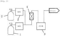
Fig. 2 ] is a schematic drawing showing an analyzer for performing evaluation in Examples 3 to 10. - [
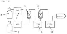
Fig. 3 ] is a schematic drawing showing an analyzer for performing evaluation in Examples 11 to 19. - Hereinafter, the method for removing the halogen fluoride from the mixed gas (hereinafter referred to as "halogen fluoride mixed gas" or "mixed gas" in some cases) containing the halogen fluoride containing bromine or iodine and another gas component, as well as the quantitative analysis method and the quantitative analyzer for the halogen fluoride in the mixed gas will be explained in detail.
- As the halogen fluoride containing bromine or iodine, one or at least two selected from BrF, BrF3, BrF5, IF3, IF5 and IF7 is/are used.
- Another gas component contained in the mixed gas includes impurity components and diluent gas, etc.
- The impurity components include gases such as oxygen, nitrogen, carbon dioxide and tetrafluoromethane, etc.; as well as volatile metal fluorides such as silicon tetrafluoride, sulfur hexafluoride, tungsten hexafluoride and chromium pentafluoride, etc. Many of them originate from halogen fluoride production. Further, the above diluent gas components include inert gases such as nitrogen, helium and argon, etc. and they are mixed in from the viewpoint of safety and corrosion, etc.
- The content of another gas component in the mixed gas may be generally an impurity gas quantity of about 1volppm to 5vol% with respect to the halogen fluoride or may be generally a diluent gas quantity of about 10 to 90vol%. Meanwhile, the above content may be a quantity outside these ranges and is not particularly limited.
- The mixed gas may contain only one of another gas component and may also contain two or more of them. If two or more of the other gas components are included, their content is not particularly limited. Two or more kinds of trace quantities of other gas components may be contained, two or more kinds of large quantities of other gas components may be contained, or a trace quantity of another gas component and a large quantity of another gas component may be contained in a mixed state.
- In accordance with the method for removing in the present invention, the halogen fluoride in the mixed gas is removed.
- The quantitative analysis method in the present invention can analyze not only trace components alone, or a large quantity of components alone, but can also quantitatively analyze a component in which the trace components and a large quantity of components are mixed.
- According to the present invention, first, the mixed gas containing the halogen fluoride and another gas component is made to react with a removing agent, thereby removing the halogen fluoride and also removing the produced by-products.
- As the removing agent, a metal chloride, metal bromide and metal iodide can be used.
- During the reaction with the removing agent, the halogen portion (excluding fluorine) and the fluorine portion in the halogen fluoride are separated, and the fluorine portion reacts with metal salt of the removing agent to become metal salt fluoride, so that chlorine, bromine and iodine are generated to be recovered. As for the quantity of the removing agent, the removing agent could be contained in an excessive quantity equal to or larger than the reaction equivalent with respect to the halogen fluoride. Further, in case of performing a successive treatment, the quantity of the removing agent could be an excessive quantity with respect to a circulation quantity, for example, 3 to 30 times the reaction equivalent, preferably, 5 to 10 times the reaction equivalent.
- As the metal chloride, a potassium chloride, sodium chloride, magnesium chloride, calcium chloride or barium chloride is suitable, because it is available as a comparatively high-purity and inexpensive reagent. As the metal bromide, a potassium bromide, sodium bromide, magnesium bromide, calcium bromide or barium bromide is suitable, because it is available as a comparatively high-purity and inexpensive reagent. As the metal iodide, a potassium iodide, sodium iodide, magnesium iodide, calcium iodide or barium iodide is suitable, because it is available as a comparatively high-purity and inexpensive reagent.
- For example, when potassium chloride is used as the removing agent and is made to react with bromine pentafluoride, due to the chemical reaction of Formula (1) indicated below, potassium fluoride, bromine and chlorine are generated.
10KCl + 2BrF5 -> 10KF + Br2 + 5Cl2 ... (1)
- When potassium bromide is used as the removing agent and is made to react with bromine pentafluoride, due to the chemical reaction of Formula (2) indicated below, potassium fluoride and bromine are generated.
5KBr + BrF5 -> 5KF + 3Br2 ... (2)
When potassium iodide is used as the removing agent and is made to react with iodine heptafluoride, due to the chemical reaction of Formula (3) indicated below, potassium fluoride and iodine are generated.
7KI + IF7 -> 7KF + 4I2 ... (3)
- The reaction of the halogen fluoride with the removing agent can be performed at, for example, 10°C or higher to lower than 300°C, and the reaction also proceeds comparatively easily at approximately room temperature. Meanwhile, in order to increase the reaction speed and completely terminate the substitution reaction, the reaction temperature is preferably 100°C or higher and more preferably 150°C or higher when the removing agent is bromide or iodide. Further, if the removing agent is chloride, the reaction temperature is preferably 10°C or higher to lower than 100°C, more preferably 15°C or higher to 95°C or lower and still more preferably 20°C or higher to 90°C or lower. If the temperature is increased too much, it could corrode pipes. The method according to the present invention would rarely cause the pipe blockage due to substance transfer by a reaction product.
- The above reaction is carried out in a normal gas phase. When the mixed gas containing the halogen fluoride and another gas component is made to pass through a reaction pipe filled with the removing agent and to react with the removing agent therein, the metal fluoride deposits and remains inside the reaction pipe, so that another gas component and by-product halogen molecules are emitted from the reaction pipe, and hence another gas component in the mixed gas does not substantially react with the removing agent.
- The above by-products such as chlorine, bromine and iodine are adsorbed or absorbed to be removed by making the reaction product contact with an adsorbing agent or absorbing agent. For example, adsorbing agents such as silica gels, molecular sieves and activated carbon, reacting agents such as iron particles, copper particles and zinc particles or absorbing agents containing an alkali aqueous solution can be used. The alkali aqueous solution indicates one having a pH value of about 9 to 14, but is not particularly limited thereto.
- According to the method for removing in the present invention, the comparatively stable gases such as tetrafluoromethane and sulfur hexafluoride in another gas component (residual gas) which is neither adsorbed nor absorbed are adsorbed by the adsorbing agent such as activated carbon and zeolite, while the gas components having comparatively high reactivity such as a silicon tetrafluoride, tungsten hexafluoride and chromium pentafluoride are separated by being dissolved by soda lime, etc. The inert gases such as nitrogen and argon as the residual impurity components can be reused as a diluent gas or be emitted into the atmosphere.
- Meanwhile, according to the quantitative analysis method in the present invention, the quantitative analysis is conducted by a gas chromatograph on another gas component (residual gas) which is neither adsorbed nor absorbed, and thereby another gas component contained in the mixed gas is capable of being quantitatively analyzed based on weight variations before and after the reaction as well as the result of the quantitative analysis in the residual gas.
- A filler for a gas chromatographic column can be optionally selected based on another gas component as targeted, and molecular sieves 13X are preferable in case of quantitatively analyzing oxygen and nitrogen. Further, a detector for the gas chromatograph can also be optionally selected, while a thermal conductivity detector (TCD) is preferable from the viewpoint of practicality.
- Next, a further concrete explanation will be made by using
Fig. 1 showing an apparatus used for the analysis method according to the present invention. - The analyzer according to the present invention comprises a
sample gas cylinder 1 filled with a mixed gas containing halogen fluoride and another gas component, acylinder 2 filled with a diluent gas, pipes connected to these containers andair supplying mechanisms 3 for these pipes, a halogenfluoride removing tank 4, a by-product removing tank 5 and a gas chromatograph 7. The analyzer also comprises a flow path switching valve 6 and ascrubbing tank 8 for emission, if necessary. The halogen fluoride removing tank is filled with a removing agent and, at the same time, a (non-illustrated) heating means is provided if necessary, while the by-product removing tank is filled with the above-mentioned adsorbing/absorbing agent. The diluent gas is mixed with a sample gas, while it can also be used as a carrier gas for the measurement using the gas chromatograph. InFig. 1 , the diluent gas from thesame cylinder 2 is mixed with the sample gas, while the carrier gas may be supplied from another cylinder. As the carrier gas, the inert gases such as a nitrogen gas, helium and argon, as well as a hydrogen gas can be used. - The mixed gas is sent together with the diluent gas to the halogen
fluoride removing tank 4 through theair supplying mechanism 3 by, for example, a mass flow controller (MFC), so that the mixed gas is reacted with the removing agent and the by-products after the reaction is removed in the by-product removing tank 5. Then, the remaining gas is mixed with the diluent gas if necessary and passes through, as the sample gas, a sample measuring pipe and a flowmeter to be quantitatively analyzed in the gas chromatograph 7. While the sample gas is exhausted after the quantitative analysis, an exhaust gas can also be exhausted after having impurities removed, if necessary, through thescrubbing tank 8 filled with an adsorbing agent such as activated carbon and zeolite or a decomposing agent such as soda lime. - The sample gas having been introduced into the gas chromatograph is separated in the column filled with a filler for the gas chromatograph, and detected by the thermal conductivity detector. A peak area of a standard gas analyzed beforehand in accordance with the same operation is compared with a peak area of a trace component of the sample gas, so that the concentration of the trace component can be known.
- The invention according to the present embodiment will be concretely explained further hereinafter in accordance with examples, while the invention according to the present embodiment is not limited to only the examples described below.
- A gas composition containing bromine pentafluoride was analyzed as a sample gas in accordance with the quantitative analysis method according to the present invention. The analysis was conducted by means of an analyzer shown in
Fig. 1 . - The halogen
fluoride removing tank 4 filled with potassium bromide as the removing agent was used, an adsorbing pipe filled with silica gels was used as the by-product removing tank 5, and a column filled with the molecular sieves 13X was used as the gas chromatograph 7. The reaction of the sample gas and the potassium bromide was set to 200°C. Further, helium was used as the carrier gas. - According to the analysis result using the gas chromatograph, the sample gas contained at most 240volppm of N2 and 5volppm of O2 and the remainder was composed of bromine pentafluoride. When a column inlet and the detector of the gas chromatograph were checked, no corrosion due to the bromine pentafluoride was seen.
- A gas composition containing iodine heptafluoride was analyzed as a sample gas in accordance with the quantitative analysis method according to the present invention. The analysis was conducted by means of the analyzer shown in
Fig. 1 . - The halogen
fluoride removing tank 4 filled with potassium iodide as the removing agent was used, an adsorbing pipe filled with silica gels was used as the by-product removing tank 5, and a column filled with the molecular sieves 13X was used as the gas chromatograph 7. The reaction of the sample gas and the potassium iodide was set to 200°C. Further, helium was used as the carrier gas. - According to the analysis result using the gas chromatograph, the sample gas was composed of at most 320volppm of N2 and 5volppm of O2, and the remainder was composed of iodine heptafluoride. When a column inlet and the detector of the gas chromatograph were checked, no corrosion due to the iodine heptafluoride was recognized.
- Except for using a reaction pipe filled with Ca(OH)2 in place of the removing agent, the analysis was conducted with the same method as in Example 1. The temperature of the reaction pipe was set to 200°C.
- As a result of the reaction of the bromine pentafluoride and Ca(OH)2, a large quantity of O2 was detected and therefore O2 and N2 were not separated, so that N2 could not be quantified.
- As shown in
Fig. 2 , a cylindrical halogenfluoride removing tank 4 having an inner diameter of 50.8mm and a length of 900mm was filled with calcium chloride (produced by Tokuyama; 2560g) having a particle size of 3 to 20mm. The bromine pentafluoride from the sample gas cylinder 1 (sample container) was diluted from thediluent gas cylinder 2 to have a concentration of 10vol% by nitrogen, and the thus diluted gas was distributed into the halogenfluoride removing tank 4 under conditions of an empty cylinder reference linear velocity of 0.6m/min, 25°C and atmospheric pressure. An infrared spectral analyzer (FT-IR) 9 was connected to an emission port of the halogenfluoride removing tank 4, the bromine pentafluoride gas concentration of a fluid exiting from the halogenfluoride removing tank 4 was measured, and the distribution of the bromine pentafluoride was stopped when the concentration exceeded 1ppm, so as to determine the quantity of processing of the bromine pentafluoride having been processed until the distribution was stopped. As a result, bromine pentafluoride of 201g could be removed as shown in Table 1 and no rapid heat generation nor no blockage in pipes, etc. were present at that time. - Except for using potassium chloride (produced by Kanto Chemical) in place of the calcium chloride and setting the temperature of the halogen
fluoride removing tank 4 to 90°C, the bromine pentafluoride was processed in accordance with the same method as in Example 3. The results are shown in Table 1. No blockage in pipes, etc. was confirmed. - Except for using magnesium chloride (produced by Kanto Chemical) in place of the calcium chloride, the bromine pentafluoride was processed in accordance with the same method as in Example 3. The processing results are shown in Table 1. No blockage in pipes, etc. was confirmed.
- Except for setting the concentration of the distributed bromine pentafluoride to 1vol%, the bromine pentafluoride was processed in accordance with the same method as in Example 3. The processing results are shown in Table 1. No blockage in pipes, etc. was confirmed.
- Except for setting the concentration of the distributed bromine pentafluoride to 20vol%, the bromine pentafluoride was processed in accordance with the same method as in Example 3. The processing results are shown in Table 1. No blockage in pipes, etc. was confirmed.
- Except for using iodine heptafluoride as a processing gas, measuring the iodine heptafluoride gas concentration of the fluid exiting from the halogen
fluoride removing tank 4, and stopping the distribution of the iodine heptafluoride when the concentration exceeded 1ppm, the iodine heptafluoride was processed in accordance with the same method as in Example 3. The processing results are shown in Table 1. No blockage in pipes, etc. was confirmed. - Except for using potassium iodide (produced by Kanto Chemical) in place of the calcium chloride and setting the temperature of the halogen
fluoride removing tank 4 to 100°C, the bromine pentafluoride was processed in accordance with the same method as in Example 3. The processing results are shown in Table 1. No blockage in pipes, etc. was confirmed. - Except for using iodine heptafluoride as the processing gas, using potassium iodide (produced by Kanto Chemical) in place of calcium chloride, setting the temperature in the halogen
fluoride removing tank 4 to 100°C, measuring the iodine heptafluoride gas concentration of the fluid exiting from the halogenfluoride removing tank 4, and stopping the distribution of the iodine heptafluoride when the concentration exceeded 1ppm, the iodine heptafluoride was processed in accordance with the same method as in Example 3. The processing results are shown in Table 1. No blockage in pipes, etc. was confirmed. - As shown in
Fig. 3 , the bromine pentafluoride was processed in accordance with the same method as in Example 3 except for: providing, at theexhaust port 9 of an infraredspectral analyzer 9, a cylindrical by-product removing tank 5 having an inner diameter of 76.2mm and a length of 900mm, filled with silica gels (produced by Kanto Chemical; 2038g) having a particle size of 2 to 4mm; connecting an ultraviolet-visible absorptiometer (UV-Vis) 10 to the emission port of the by-product removing tank 5; measuring the chlorine gas concentration of the fluid exiting from the by-product removing tank 5; and stopping the distribution of the bromine pentafluoride when the concentration exceeded 1ppm. The processing results are shown in Table 1. No blockage in pipes, etc. was confirmed. - <Example 12>
- Except for using the molecular sieves 13X (produced by Union Showa) in place of the silica gels, the bromine pentafluoride was processed in accordance with the same method as in Example 11. The processing results are shown in Table 1. No blockage in pipes, etc. was confirmed.
- Except for using the molecular sieves 5A (produced by Union Showa) in place of the silica gels, the bromine pentafluoride was processed in accordance with the same method as in Example 11. The processing results are shown in Table 1. No blockage in pipes, etc. was confirmed.
- Except for using activated carbons (granular SHIRASAGI®; produced by Osaka Gas Chemicals) in place of the silica gels, the bromine pentafluoride was processed in accordance with the same method as in Example 11. The processing results are shown in Table 1. No blockage in pipes, etc. was confirmed.
- Except for using Al2O3 of 90wt% - Na2O of 10wt% (produced by BASF) in place of the silica gels, the bromine pentafluoride was processed in accordance with the same method as in Example 11. The processing results are shown in Table 1. No blockage in pipes, etc. was confirmed.
- Except for using granular Fe (produced by Kanto Chemical) in place of the silica gels, the bromine pentafluoride was processed in accordance with the same method as in Example 11. The processing results are shown in Table 1. No blockage in pipes, etc. was confirmed.
- Except for using granular Cu (produced by Kanto Chemical) in place of the silica gels, the bromine pentafluoride was processed in accordance with the same method as in Example 11. The processing results are shown in Table 1. No blockage in pipes, etc. was confirmed.
- Except for using granular Zn (produced by Kanto Chemical) in place of the silica gels, the bromine pentafluoride was processed in accordance with the same method as in Example 11. The processing results are shown in Table 1. No blockage in pipes, etc. was confirmed.
- Except for setting the temperature in the halogen fluoride removing tank to 150°C, the bromine pentafluoride was processed to be removed in accordance with the same method as in Example 3. As a result, approximately the same quantity of bromine pentafluoride as the one in Example 3 could be processed, while slight corrosion in pipes was confirmed.
- The bromine pentafluoride was processed to be removed in accordance with the same method as in Example 3 except for using, as the removing agent, in place of the calcium chloride, only soda lime (produced by Yabashi Industries; composed of calcium hydroxide Ca(OH)2 (about 75wt%), water H2O (about 20wt%), sodium hydroxide NaOH (about 3wt%) and potassium hydroxide KOH(about 1wt%)). As a result, since the value of a pressure gauge installed at the inlet of the halogen fluoride removing tank increased during the reaction, it was determined that the halogen fluoride removing tank was blocked, and the distribution of the bromine pentafluoride was stopped. The quantity of the bromine pentafluoride having been processed until the stop of the distribution was 47g. When the halogen fluoride removing tank was opened and its interior was observed, generation of brown slurry was recognized. The results are shown in Table 1.
[Table 1] Processing gas (halogen fluoride) Diluent gas Removing agent in halogen fluoride removing tank (tank temperature) Content in by-product removing tank (tank temperature) Halogen fluoride removal quantity Example 3 BrF5 10vol% N2 90vol% CaCl2 25°C Not used 230g Example 4 BrF5 10vol% N2 90vol% KCl 90°C Not used 87g Example 5 BrF5 10vol% N2 90vol% MgCl2 25°C Not used 152g Example 6 BrF5 1vol% N2 99vol% CaCl2 25°C Not used 262g Example 7 BrF5 20vol% N2 80vol% CaCl2 25°C Not used 179g Example 8 IF7 10vol% N2 90vol% CaCl2 25°C Not used 171g Example 9 BrF5 10vol% N2 90vol% KBr 100°C Not used 183g Example 10 IF7 10vol% N2 90vol% KI 100°C Not used 157g Example 11 BrF5 10vol% N2 90vol% CaCl2 25°C Silica gels 25°C 202g Example 12 BrF5 10vol% N2 90vol% CaCl2 25°C Molecular sieves 13X 25°C 215g Example 13 BrF5 10vol% N2 90vol% CaCl2 25°C Molecular sieves 5A 25°C 202g Example 14 BrF5 10vol% N2 90vol% CaCl2 25°C Activated carbon 25°C 208g Example 15 BrF5 10vol% N2 90vol% CaCl2 25°C Al2O3 of 90wt% - Na2O of 10wt% 25°C 136g Example 16 BrF5 10vol% N2 90vol% CaCl2 25°C Fe particles 25°C 78g Example 17 BrF5 10vol% N2 90vol% CaCl2 25°C Cu particles 25°C 96g Example 18 BrF5 10vol% N2 90vol% CaCl2 25°C Zn particles 25°C 124g Example 19 BrF5 10vol% N2 90vol% CaCl2 150°C Not used 220g Comparative Example 2 BrF5 10vol% N2 90vol% Soda lime 25°C Not used 47g - It is possible to provide a method for removal in which a halogen fluoride containing bromine or iodine in a mixed gas can be easily separated. Due to this, a gas used in semiconductor processing can be subjected to exhaust gas treatment safely, with high treatment efficiency and continuously during a long period.
- Moreover, according to the present invention, it is possible to provide a quantitative analysis method for trace impurities in a halogen fluoride. This allows a high-purity halogen fluoride to be stably supplied.
-
- 1:
- Sample gas cylinder
- 2:
- Diluent gas cylinder
- 3:
- Air supplying mechanism
- 4:
- Halogen fluoride removing tank
- 5:
- By-product removing tank
- 6:
- Flow path switching valve
- 7:
- Gas chromatograph
- 8:
- Scrubbing tank
- 9:
- Infrared spectral analyzer (FT-IR)
- 10:
- Ultraviolet-visible absorptiometer (UV-Vis)
Claims (9)
- A method for removing a halogen fluoride in a mixed gas, characterized by reacting a mixed gas containing the halogen fluoride including bromine or iodine and another gas component with a removing agent which is a chloride, bromide or iodide of an element selected from the group consisting of potassium, sodium, magnesium, calcium or barium.
- The method for removing a halogen fluoride according to Claim 1, wherein a reaction temperature with the removing agent is 10°C or higher and lower than 300°C.
- The method for removing a halogen fluoride according to Claim 1, wherein the halogen fluoride is at least one selected from BrF, BrF3, BrF5, IF3, IF5 and IF7.
- The method for removing a halogen fluoride according to any one of Claims 1 to 3, wherein the removing agent is a chloride of an element selected from the group consisting of potassium, sodium, magnesium, calcium and barium, and a reaction temperature of the mixed gas and the chloride is 10°C or higher and lower than 100°C.
- The method for removing a halogen fluoride according to any one of Claims 1 to 3, wherein the removing agent is a bromide or iodide of an element selected from the group consisting of potassium, sodium, magnesium, calcium and barium and a reaction temperature of the mixed gas and the bromide or iodide is 100°C or higher and lower than 300°C.
- The method for removing a halogen fluoride according to Claim 1, wherein another gas component contains at least one selected from oxygen, nitrogen, carbon dioxide, helium, argon, tetrafluoromethane, silicon tetrafluoride, sulfur hexafluoride, tungsten hexafluoride and chromium pentafluoride.
- The method for removing a halogen fluoride according to Claim 1, wherein a reaction product is caused to contact with at least one adsorbing agent selected from silica gels, molecular sieves, activated carbon, iron particles, copper particles and zinc particles, or an alkali aqueous solution, thereby removing reaction by-products.
- A quantitative analysis method for a gas component contained in a halogen fluoride mixed gas, characterized by reacting a mixed gas containing a halogen fluoride including bromine or iodine and another gas component with a removing agent, thereby removing the halogen fluoride in the mixed gas, further removing produced by-products and quantitatively analyzing a residual gas by a gas chromatograph,
wherein the removing agent is a chloride, bromide or iodide of an element selected from the group consisting of potassium, sodium, magnesium, calcium and barium. - A quantitative analyzer for a gas component contained in a halogen fluoride mixed gas, comprising: a sample container filled with a mixed gas containing a halogen fluoride including bromine or iodine and another gas component; a halogen fluoride removing tank; a by-product removing tank; and a gas chromatograph, wherein a removing agent is filled in the halogen fluoride removing tank, and a residual gas obtained by removing the halogen fluoride and the by-products from a sample gas is introduced into the gas chromatograph.
Applications Claiming Priority (3)
| Application Number | Priority Date | Filing Date | Title |
|---|---|---|---|
| JP2018239516 | 2018-12-21 | ||
| JP2019194301 | 2019-10-25 | ||
| PCT/JP2019/048055 WO2020129726A1 (en) | 2018-12-21 | 2019-12-09 | Method for removing halogen fluoride, quantitative analysis method for gas component contained in halogen fluoride mixed gas, and quantitative analyzer |
Publications (2)
| Publication Number | Publication Date |
|---|---|
| EP3900810A1 true EP3900810A1 (en) | 2021-10-27 |
| EP3900810A4 EP3900810A4 (en) | 2022-09-07 |
Family
ID=71102895
Family Applications (1)
| Application Number | Title | Priority Date | Filing Date |
|---|---|---|---|
| EP19897627.6A Pending EP3900810A4 (en) | 2018-12-21 | 2019-12-09 | HALOGEN FLUORIDE REMOVAL METHOD, QUANTITATIVE ANALYSIS METHOD FOR GASEOUS COMPONENT CONTAINED IN HALOGEN FLUORIDE MIXED GAS, AND QUANTITATIVE ANALYZER |
Country Status (9)
| Country | Link |
|---|---|
| US (1) | US11779877B2 (en) |
| EP (1) | EP3900810A4 (en) |
| JP (2) | JP7491222B2 (en) |
| KR (1) | KR102616989B1 (en) |
| CN (1) | CN113164862A (en) |
| IL (1) | IL283832B (en) |
| SG (1) | SG11202106469WA (en) |
| TW (1) | TWI731514B (en) |
| WO (1) | WO2020129726A1 (en) |
Cited By (1)
| Publication number | Priority date | Publication date | Assignee | Title |
|---|---|---|---|---|
| US11984308B2 (en) | 2019-11-27 | 2024-05-14 | Resonac Corporation | Method for measuring concentration of fluorine gas in halogen fluoride-containing gas using mass spectrometer |
Families Citing this family (5)
| Publication number | Priority date | Publication date | Assignee | Title |
|---|---|---|---|---|
| CN115768738B (en) | 2020-08-24 | 2025-12-09 | 株式会社力森诺科 | Refining method of haloalkane |
| CN112675683A (en) * | 2020-12-29 | 2021-04-20 | 四川红华实业有限公司 | Fluorine-containing tail gas purification treatment method |
| CN113663480B (en) * | 2021-08-23 | 2024-11-05 | 云南国钛金属股份有限公司 | A treatment device for chlorination furnace chlorine-containing waste gas |
| KR102629373B1 (en) * | 2023-05-30 | 2024-01-25 | 주식회사 코스모스랩 | Device of analyzing performance of filter for zinc-bromide battery |
| CN119964864A (en) * | 2024-12-26 | 2025-05-09 | 中国辐射防护研究院 | A device and method for dry removal of high concentration ClF3 in fluorine-containing tail gas |
Family Cites Families (13)
| Publication number | Priority date | Publication date | Assignee | Title |
|---|---|---|---|---|
| US2732410A (en) | 1956-01-24 | Process for preparing tetrafluoro | ||
| JPH0797106B2 (en) | 1988-12-16 | 1995-10-18 | セントラル硝子株式会社 | Fluorine-containing gas component concentration measuring method and apparatus |
| JP2725876B2 (en) * | 1990-04-27 | 1998-03-11 | セントラル硝子株式会社 | Method and apparatus for analyzing trace impurities in fluorine or chlorine fluoride gas |
| EP0459671A3 (en) | 1990-05-29 | 1993-03-31 | Mobil Oil Corporation | Method and apparatus for the removal of film strip material from a plurality of film reels or reel cartridges |
| JPH08215538A (en) | 1995-02-17 | 1996-08-27 | Central Glass Co Ltd | Method for removing halogen-containing gas |
| JPH08215539A (en) * | 1995-02-17 | 1996-08-27 | Central Glass Co Ltd | Treatment of halogen-containing gas |
| JP4357018B2 (en) | 1998-11-25 | 2009-11-04 | 関東電化工業株式会社 | Detoxification method using halogenated gas treatment agent |
| US6309618B1 (en) | 1999-03-12 | 2001-10-30 | Showa Denko K. K. | Method for treating exhaust gas containing fluorine-containing interhalogen compound, and treating agent and treating apparatus |
| JP4488545B2 (en) | 1999-03-12 | 2010-06-23 | 昭和電工株式会社 | Treatment method, treatment agent and treatment apparatus for exhaust gas containing halogen fluoride |
| JP4642602B2 (en) | 2005-08-24 | 2011-03-02 | 昭和電工株式会社 | Method for quantitative analysis of gas components contained in fluorine gas and apparatus used therefor |
| JP5771896B2 (en) * | 2009-02-09 | 2015-09-02 | セントラル硝子株式会社 | How to remove iodine fluoride |
| JP2012106200A (en) * | 2010-11-18 | 2012-06-07 | Central Glass Co Ltd | Removing method for halogen gas or fluoride gas by removing agent |
| JP6792158B2 (en) | 2016-02-09 | 2020-11-25 | セントラル硝子株式会社 | Fluorine compound gas purification method |
-
2019
- 2019-12-09 SG SG11202106469WA patent/SG11202106469WA/en unknown
- 2019-12-09 EP EP19897627.6A patent/EP3900810A4/en active Pending
- 2019-12-09 US US17/416,807 patent/US11779877B2/en active Active
- 2019-12-09 KR KR1020217017651A patent/KR102616989B1/en active Active
- 2019-12-09 JP JP2020561318A patent/JP7491222B2/en active Active
- 2019-12-09 WO PCT/JP2019/048055 patent/WO2020129726A1/en not_active Ceased
- 2019-12-09 CN CN201980081437.3A patent/CN113164862A/en active Pending
- 2019-12-16 TW TW108145942A patent/TWI731514B/en active
-
2021
- 2021-06-09 IL IL283832A patent/IL283832B/en unknown
-
2024
- 2024-02-16 JP JP2024022070A patent/JP2024059728A/en not_active Withdrawn
Cited By (1)
| Publication number | Priority date | Publication date | Assignee | Title |
|---|---|---|---|---|
| US11984308B2 (en) | 2019-11-27 | 2024-05-14 | Resonac Corporation | Method for measuring concentration of fluorine gas in halogen fluoride-containing gas using mass spectrometer |
Also Published As
| Publication number | Publication date |
|---|---|
| TW202032121A (en) | 2020-09-01 |
| EP3900810A4 (en) | 2022-09-07 |
| IL283832B (en) | 2022-06-01 |
| JPWO2020129726A1 (en) | 2021-11-04 |
| IL283832A (en) | 2021-07-29 |
| CN113164862A (en) | 2021-07-23 |
| KR102616989B1 (en) | 2023-12-27 |
| US20220054972A1 (en) | 2022-02-24 |
| WO2020129726A1 (en) | 2020-06-25 |
| JP2024059728A (en) | 2024-05-01 |
| JP7491222B2 (en) | 2024-05-28 |
| SG11202106469WA (en) | 2021-07-29 |
| TWI731514B (en) | 2021-06-21 |
| US11779877B2 (en) | 2023-10-10 |
| KR20210087083A (en) | 2021-07-09 |
Similar Documents
| Publication | Publication Date | Title |
|---|---|---|
| US11779877B2 (en) | Method for removing halogen fluoride, quantitative analysis method for gas component contained in halogen fluoride mixed gas, and quantitative analyzer | |
| TWI670232B (en) | Method for purifying fluorine compound gas | |
| TWI654139B (en) | Fluorine gas purification method | |
| US11572331B2 (en) | Quaternary alkyl ammonium hypochlorite solution, method of producing the same, and method for processing semiconductor wafers | |
| WO2017138366A1 (en) | Method for purifying fluorine compound gas | |
| JP4744017B2 (en) | Analysis method of trace impurities in high purity fluorine gas | |
| EP1063001A1 (en) | Purifying agent and purification method for halogen-containing exhaust gas | |
| EP4446733A1 (en) | Method for analyzing gas containing nitrosyl fluoride, and method for removing nitrosyl fluoride in gas | |
| JP5471313B2 (en) | Methods for removing chlorine trifluoride | |
| JP4642602B2 (en) | Method for quantitative analysis of gas components contained in fluorine gas and apparatus used therefor | |
| JP3260825B2 (en) | How to purify harmful gases | |
| JP5980652B2 (en) | Persulfate treatment apparatus, persulfate treatment method, oxidation-reduction potential measurement apparatus, and oxidation-reduction potential measurement method | |
| CN121001957A (en) | Methods for removing fluorine gas | |
| WO2023106244A1 (en) | Platinum group element resource recovery device, film formation system, platinum group element resource recovery tube, and platinum group element resource recovery method | |
| JP2018134571A (en) | Method for removing iodine compounds | |
| WO2010050342A1 (en) | Method and system for purifying nitrogen trifluoride containing halogen or halogen compound as impurity | |
| CN120379746A (en) | Exhaust gas treatment method and exhaust gas treatment device | |
| JP2008086913A (en) | Method for removing fluorine in fluorine-containing gas | |
| Mukhortov et al. | Interaction of trichloromethane and tetrachloromethane with nitrogen trifluoride | |
| JP2006043536A (en) | Method for decomposing nitrogen compound |
Legal Events
| Date | Code | Title | Description |
|---|---|---|---|
| STAA | Information on the status of an ep patent application or granted ep patent |
Free format text: STATUS: THE INTERNATIONAL PUBLICATION HAS BEEN MADE |
|
| PUAI | Public reference made under article 153(3) epc to a published international application that has entered the european phase |
Free format text: ORIGINAL CODE: 0009012 |
|
| STAA | Information on the status of an ep patent application or granted ep patent |
Free format text: STATUS: REQUEST FOR EXAMINATION WAS MADE |
|
| 17P | Request for examination filed |
Effective date: 20210708 |
|
| AK | Designated contracting states |
Kind code of ref document: A1 Designated state(s): AL AT BE BG CH CY CZ DE DK EE ES FI FR GB GR HR HU IE IS IT LI LT LU LV MC MK MT NL NO PL PT RO RS SE SI SK SM TR |
|
| DAV | Request for validation of the european patent (deleted) | ||
| DAX | Request for extension of the european patent (deleted) | ||
| REG | Reference to a national code |
Ref country code: DE Ref legal event code: R079 Free format text: PREVIOUS MAIN CLASS: B01D0053140000 Ipc: B01D0053680000 |
|
| A4 | Supplementary search report drawn up and despatched |
Effective date: 20220805 |
|
| RIC1 | Information provided on ipc code assigned before grant |
Ipc: G01N 33/00 20060101ALI20220801BHEP Ipc: G01N 30/14 20060101ALI20220801BHEP Ipc: G01N 30/88 20060101ALI20220801BHEP Ipc: G01N 30/06 20060101ALI20220801BHEP Ipc: B01D 53/68 20060101AFI20220801BHEP |
|
| RAP1 | Party data changed (applicant data changed or rights of an application transferred) |
Owner name: RESONAC CORPORATION |
|
| RAP3 | Party data changed (applicant data changed or rights of an application transferred) |
Owner name: RESONAC CORPORATION |
|
| STAA | Information on the status of an ep patent application or granted ep patent |
Free format text: STATUS: EXAMINATION IS IN PROGRESS |
|
| 17Q | First examination report despatched |
Effective date: 20241113 |
|
| GRAP | Despatch of communication of intention to grant a patent |
Free format text: ORIGINAL CODE: EPIDOSNIGR1 |
|
| STAA | Information on the status of an ep patent application or granted ep patent |
Free format text: STATUS: GRANT OF PATENT IS INTENDED |
|
| INTG | Intention to grant announced |
Effective date: 20260205 |