EP3900120B1 - Hochvolt-vorrichtung - Google Patents
Hochvolt-vorrichtung Download PDFInfo
- Publication number
- EP3900120B1 EP3900120B1 EP19827650.3A EP19827650A EP3900120B1 EP 3900120 B1 EP3900120 B1 EP 3900120B1 EP 19827650 A EP19827650 A EP 19827650A EP 3900120 B1 EP3900120 B1 EP 3900120B1
- Authority
- EP
- European Patent Office
- Prior art keywords
- cover
- housing
- protective cover
- voltage device
- electrical
- Prior art date
- Legal status (The legal status is an assumption and is not a legal conclusion. Google has not performed a legal analysis and makes no representation as to the accuracy of the status listed.)
- Active
Links
Images




Classifications
-
- H—ELECTRICITY
- H05—ELECTRIC TECHNIQUES NOT OTHERWISE PROVIDED FOR
- H05K—PRINTED CIRCUITS; CASINGS OR CONSTRUCTIONAL DETAILS OF ELECTRIC APPARATUS; MANUFACTURE OF ASSEMBLAGES OF ELECTRICAL COMPONENTS
- H05K5/00—Casings, cabinets or drawers for electric apparatus
- H05K5/02—Details
- H05K5/0217—Mechanical details of casings
- H05K5/0221—Locks; Latches
-
- B—PERFORMING OPERATIONS; TRANSPORTING
- B60—VEHICLES IN GENERAL
- B60L—PROPULSION OF ELECTRICALLY-PROPELLED VEHICLES; SUPPLYING ELECTRIC POWER FOR AUXILIARY EQUIPMENT OF ELECTRICALLY-PROPELLED VEHICLES; ELECTRODYNAMIC BRAKE SYSTEMS FOR VEHICLES IN GENERAL; MAGNETIC SUSPENSION OR LEVITATION FOR VEHICLES; MONITORING OPERATING VARIABLES OF ELECTRICALLY-PROPELLED VEHICLES; ELECTRIC SAFETY DEVICES FOR ELECTRICALLY-PROPELLED VEHICLES
- B60L3/00—Electric devices on electrically-propelled vehicles for safety purposes; Monitoring operating variables, e.g. speed, deceleration or energy consumption
- B60L3/04—Cutting off the power supply under fault conditions
-
- B—PERFORMING OPERATIONS; TRANSPORTING
- B60—VEHICLES IN GENERAL
- B60L—PROPULSION OF ELECTRICALLY-PROPELLED VEHICLES; SUPPLYING ELECTRIC POWER FOR AUXILIARY EQUIPMENT OF ELECTRICALLY-PROPELLED VEHICLES; ELECTRODYNAMIC BRAKE SYSTEMS FOR VEHICLES IN GENERAL; MAGNETIC SUSPENSION OR LEVITATION FOR VEHICLES; MONITORING OPERATING VARIABLES OF ELECTRICALLY-PROPELLED VEHICLES; ELECTRIC SAFETY DEVICES FOR ELECTRICALLY-PROPELLED VEHICLES
- B60L50/00—Electric propulsion with power supplied within the vehicle
- B60L50/50—Electric propulsion with power supplied within the vehicle using propulsion power supplied by batteries or fuel cells
- B60L50/60—Electric propulsion with power supplied within the vehicle using propulsion power supplied by batteries or fuel cells using power supplied by batteries
- B60L50/64—Constructional details of batteries specially adapted for electric vehicles
-
- H—ELECTRICITY
- H05—ELECTRIC TECHNIQUES NOT OTHERWISE PROVIDED FOR
- H05K—PRINTED CIRCUITS; CASINGS OR CONSTRUCTIONAL DETAILS OF ELECTRIC APPARATUS; MANUFACTURE OF ASSEMBLAGES OF ELECTRICAL COMPONENTS
- H05K5/00—Casings, cabinets or drawers for electric apparatus
- H05K5/02—Details
- H05K5/0217—Mechanical details of casings
- H05K5/0226—Hinges
-
- H—ELECTRICITY
- H05—ELECTRIC TECHNIQUES NOT OTHERWISE PROVIDED FOR
- H05K—PRINTED CIRCUITS; CASINGS OR CONSTRUCTIONAL DETAILS OF ELECTRIC APPARATUS; MANUFACTURE OF ASSEMBLAGES OF ELECTRICAL COMPONENTS
- H05K5/00—Casings, cabinets or drawers for electric apparatus
- H05K5/02—Details
- H05K5/03—Covers
-
- B—PERFORMING OPERATIONS; TRANSPORTING
- B60—VEHICLES IN GENERAL
- B60L—PROPULSION OF ELECTRICALLY-PROPELLED VEHICLES; SUPPLYING ELECTRIC POWER FOR AUXILIARY EQUIPMENT OF ELECTRICALLY-PROPELLED VEHICLES; ELECTRODYNAMIC BRAKE SYSTEMS FOR VEHICLES IN GENERAL; MAGNETIC SUSPENSION OR LEVITATION FOR VEHICLES; MONITORING OPERATING VARIABLES OF ELECTRICALLY-PROPELLED VEHICLES; ELECTRIC SAFETY DEVICES FOR ELECTRICALLY-PROPELLED VEHICLES
- B60L2240/00—Control parameters of input or output; Target parameters
- B60L2240/80—Time limits
-
- H—ELECTRICITY
- H01—ELECTRIC ELEMENTS
- H01R—ELECTRICALLY-CONDUCTIVE CONNECTIONS; STRUCTURAL ASSOCIATIONS OF A PLURALITY OF MUTUALLY-INSULATED ELECTRICAL CONNECTING ELEMENTS; COUPLING DEVICES; CURRENT COLLECTORS
- H01R13/00—Details of coupling devices of the kinds covered by groups H01R12/70 or H01R24/00 - H01R33/00
- H01R13/66—Structural association with built-in electrical component
- H01R13/70—Structural association with built-in electrical component with built-in switch
- H01R13/701—Structural association with built-in electrical component with built-in switch the switch being actuated by an accessory, e.g. cover, locking member
-
- H—ELECTRICITY
- H01—ELECTRIC ELEMENTS
- H01R—ELECTRICALLY-CONDUCTIVE CONNECTIONS; STRUCTURAL ASSOCIATIONS OF A PLURALITY OF MUTUALLY-INSULATED ELECTRICAL CONNECTING ELEMENTS; COUPLING DEVICES; CURRENT COLLECTORS
- H01R2201/00—Connectors or connections adapted for particular applications
- H01R2201/26—Connectors or connections adapted for particular applications for vehicles
-
- Y—GENERAL TAGGING OF NEW TECHNOLOGICAL DEVELOPMENTS; GENERAL TAGGING OF CROSS-SECTIONAL TECHNOLOGIES SPANNING OVER SEVERAL SECTIONS OF THE IPC; TECHNICAL SUBJECTS COVERED BY FORMER USPC CROSS-REFERENCE ART COLLECTIONS [XRACs] AND DIGESTS
- Y02—TECHNOLOGIES OR APPLICATIONS FOR MITIGATION OR ADAPTATION AGAINST CLIMATE CHANGE
- Y02T—CLIMATE CHANGE MITIGATION TECHNOLOGIES RELATED TO TRANSPORTATION
- Y02T10/00—Road transport of goods or passengers
- Y02T10/60—Other road transportation technologies with climate change mitigation effect
- Y02T10/70—Energy storage systems for electromobility, e.g. batteries
Definitions
- the present invention relates to a high-voltage device for a high-voltage application.
- a battery module comprises a housing that electrically insulates the electrical pole and through which contact protection is provided for the screw and the electrical pole.
- One of the common systems is to use an electrical loop to query all removable parts (e.g. plugs and covers) and, if this query loop is interrupted, those relevant to high-voltage safety Switch off areas and de-energize them. In many products, this is done using two additional pins on an existing connector (e.g. vehicle signal connector or air conditioning compressor tap). Lids or other removable parts have a mechanical link that prevents the lid from being removed before the plug is pulled out. This means that before the cover is opened, this plug is pulled out and the entire system is discharged.
- an existing connector e.g. vehicle signal connector or air conditioning compressor tap
- the background of the invention is that in existing systems an additional plug interface is required in order to enable the time delay between opening the high-voltage interlock line and access to high-voltage connections.
- the high-voltage safety discharge time is usually not implemented or is implemented only with great difficulty.
- the invention specifies a high-voltage device for a high-voltage application.
- the high-voltage device comprises an electrically insulating housing with a housing cover covering the interior of the housing and covering means arranged in the interior of the housing for at least one electrical connection terminal or electrical area to be protected from contact.
- the covering means have a protective cover covering the electrical connection terminal or the electrical area, which is provided by at least one Locking element can be locked in a closed position and can be moved into an open position by an opening process, the at least one locking element for the protective cover inside the housing being designed in such a way that its release requires a period of time after which the housing cover is opened and the interruption of the housing is triggered High-voltage circuit, the electrical connection terminal or the electrical area has changed to a touch-safe state.
- high voltage is understood to mean the corresponding term used in the automotive sector, in which the voltage is above 60V.
- a covering means is understood to be an element whose material, shape and design is selected in accordance with the required protection.
- a locking element is a component that prevents direct opening. This means that, in normal handling, the locking element must first be unlocked before access to the electrical connection terminal and/or an area to be protected is possible.
- the deactivation, i.e. the unlocking of the at least one blocking element generally requires a minimum time, which is necessary so that the electrical connection terminal no longer needs to be protected.
- the covering means therefore has the advantage that after triggering a first event, such as interrupting the power supply, after an electrical connection terminal to be protected must continue to be protected from contact and/or intervention for a predetermined time, this predetermined time can at least be guaranteed. This time is guaranteed by a time function that is required to unlock the at least one locking element of the covering means. This enables a secure application for the user. This means that a sufficient discharge time can be easily ensured.
- the locking element can only be removed by a movement in a predetermined lateral direction and/or direction of rotation, and the type, length and/or mechanical resistance of this movement are dimensioned such that the removal of the locking element with a predetermined set of tools at least up to the transition into the touch-safe state.
- the receptacle interacts with the locking element in such a way that a specific movement or a combination of movements is required to deactivate the locking element.
- a part of the protective cover protrudes into a plane of the housing cover, so that the high-voltage device cannot be assembled and the electrical connection terminal to be protected cannot be put into operation again until all locking elements are activated.
- the locking elements, a last locking element to be activated or another part of the covering means prevent intended use after deactivation. This ensures that all locking elements have been activated when the device equipped with this covering means is put into operation again, so that permanent protection can be guaranteed.
- the covering means has at least one connecting means, so that the covering means can be movably attached to the electrical connection terminal or in an environment of the electrical area.
- the movable connecting means allows both access to the electrical connection terminal when it no longer needs to be protected, as well as a position in which the electrical connection terminal is protected from contact.
- the covering means is permanently arranged at a predetermined location so that it cannot be removed or lost during normal use.
- the connecting means forms a hinge, so that the protective cover is arranged pivotably.
- a hinge is a simple means by which the cover can be permanently attached to a designated location.
- the locking element is captively arranged on the protective cover or connected to it.
- captivity means that the locking element cannot be lost when the covering means is used as intended. This ensures that the function of the locking element can be guaranteed permanently. This therefore enables safe use of the covering agent.
- the locking element is a screw which is held on the protective cover in the axial direction of the screw.
- a screw is a simple and economical means that enables both a time function and a locking function.
- other locking elements such as snap hooks or a guide link are also possible, which require at least a certain amount of time to unlock.
- FIG 1 an exemplary embodiment of a high-voltage device 14 for operating a high-voltage application is shown.
- the high-voltage device 14 includes an electrically insulating housing 15 and a housing cover 16, which is still attached to the housing 15 in this figure.
- the Housing cover 16 covers a housing interior 18 of the electrically insulating housing 15.
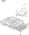
- FIG. 2 shows the high-voltage device 14 after loosening the housing screws 19 fastening the housing cover 16.
- the housing cover 16 shown here has already been removed from the housing 15.
- a contact bridge 20, which is arranged on the back of the housing cover 16 is pulled out of a plug contact 22 in the housing interior 18, so that the plug contact 22 is opened.
- An electrical signal is generated via the plug contact 22, so that an electrical connection to a battery is disconnected.
- capacitors (not shown) of the high-voltage device 14 are discharged. However, discharging the capacitors takes a certain amount of time. In order to ensure this time, a covering means 10 is provided.
- FIG 3 shows the high-voltage device 14 after the housing cover 16 has been completely removed.
- the covering means 10 shown in the exemplary embodiment has a protective cover 26 and a locking element 30.
- the locking element 30 is locked.
- the locking element 30 is a screw.
- the screw 30 is arranged on the protective cover 26 and fastens the protective cover 26 over an electrical connection terminal 34 to be protected (see Figure 4 ).
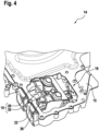
- FIG 4 the high-voltage device 14 is shown with the covering means 10 after the locking element 30 has been released.
- the screw 30 has been unscrewed from a threaded hole 38.
- This screwing process takes time due to a corresponding length L (see Figure 5 ) of the screw 30 at least for a certain time, so that the connecting terminal 34 to be protected, which here are electrical contacts, no longer needs to be protected against contact. This means that after this time the capacitors are so discharged that they can be touched safely.
- FIG. 5 the high-voltage device 14 is shown in an access position of the covering means 10.
- the protective cover 26 can be moved into the access position via a connecting means 42, which here are hinges of the covering means 10.
- the hinges 42 are fastened in the vicinity of the electrical connection terminals 34, so that the protective cover 26 can be pivoted into an access position. In this position, a locking position is provided so that the access position can be maintained. This simplifies access to the electrical connection terminal 34.
- the screw 30 is arranged captively on the protective cover 26. This means that the screw 30 carries out essentially no movement in the screw axial direction 46 with respect to the protective cover 26 during a rotational movement. In this access position, electrical lines (not shown) can be inserted into openings 50 of the housing 15 and contacted with the electrical connection terminals 34.
- Figure 6 shows the high-voltage device 14 after the covering means 10 has been properly closed. After contacting the electrical lines, the protective cover 26 can be brought back into a position in which it covers the electrical connection terminals 34.
- the protective cover 26 has an additional distance to that of the electrical connection terminals 34 (see also Figure 4 ), compared to a position where the screw 30 is screwed. Due to the fact that the screw 30 does not move in the screw axial direction 46 with respect to the protective cover 26, this distance corresponds to the length L of the screw 30. As a result, part of the protective cover 30 protrudes, as shown in Figure 4 shown, in a plane of the housing cover 16, which is attached above the protective cover 26.
- the housing cover 16 Only after the screw 30 has been screwed in completely can the housing cover 16 be attached, so that safe use can be guaranteed.
- the plug contact 22 is closed again via the contact bridge 20, so that the electrical connection to the battery is restored.
Landscapes
- Engineering & Computer Science (AREA)
- Microelectronics & Electronic Packaging (AREA)
- Life Sciences & Earth Sciences (AREA)
- Sustainable Development (AREA)
- Sustainable Energy (AREA)
- Power Engineering (AREA)
- Transportation (AREA)
- Mechanical Engineering (AREA)
- Connector Housings Or Holding Contact Members (AREA)
- Casings For Electric Apparatus (AREA)
- Details Of Connecting Devices For Male And Female Coupling (AREA)
Description
- Die vorliegende Erfindung betrifft eine Hochvolt-Vorrichtung für eine Hochvoltanwendung.
- Aktuelle Hochvolt-Systeme (Leistungselektronik, Hochvolt-Batterie, E-Motor, ...) im Automobilbereich werden mittels Sicherheitssystemen wie zum Beispiel Berührschutzmaßnahmen und Abschaltsystemen abgesichert.
- In der
DE 10 2014 012 320 B3 ist ein Batteriemodul offenbart, wobei das Batteriemodul ein den elektrischen Pol elektrisch isolierendes Gehäuse umfasst, durch welches ein Berührschutz für die Schraube und den elektrischen Pol bereitgestellt ist. - Aus der
EP 3 026 763 A1 ist eine elektrische Vorrichtung mit einem Stromkreis bekannt. Um einen direkten Zugriff auf den Stromkreis zu vermeiden und einen Bediener vor einem elektrischen Schock zu schützen, ist ein Deckel über dem Stromkreis angeordnet. Zusätzlich wird über einen Sicherheitsschalter, der vor dem Entfernen des Deckels herausgedreht werden muss, gewährleistet, dass der Stromkreis unterbrochen wird. Erst nach dem Herausdrehen des Sicherheitsschalters kann eine letzte, den Deckel haltende, Schraube entfernt werden. Während dieser Zeit kann der Stromkreis entladen werden. - Eines der gängigen Systeme ist mittels einer elektrischen Schleife alle abnehmbaren Teile (z.B. Stecker und Deckel) abzufragen und bei entsprechender Unterbrechung dieser Abfrageschleife die Hochvoltsicherheitsrelevanten Bereiche abzuschalten und spannungsfrei zu machen. In vielen Erzeugnissen erfolgt dies mittels zweier zusätzlicher Pins eines bestehenden Steckers (z. B. Fahrzeugsignalstecker oder Abgriff Klimakompressor). Deckel oder andere abnehmbare Teile weisen eine mechanische Kulisse vor, die ein Abnehmen des Deckels vor Ziehen des Steckers verhindert. Somit wird vor Öffnen des/der Deckel dieser Stecker vorab abgezogen und die Entladung des gesamten Systems erfolgt.
- Der Hintergrund der Erfindung ist, dass bei bestehenden Systemen eine zusätzliche Steckerschnittstelle benötigt wird, um den zeitlichen Versatz zwischen Öffnen Hochvolt-Interlock-Leitung und Zugang zu Hochvolt-Anschlüssen zu ermöglichen. Bei Systemen die keine elektrische Schnittstelle vorweisen, in die die Hochvolt-Interlock-Abfrage integriert werden kann, ist die Hochvolt-Sicherheits-Entladezeit meist nicht oder nur sehr umständlich realisiert.
- Es ist daher die Aufgabe der vorliegenden Erfindung eine Hochvolt-Vorrichtung anzugeben, mit welcher bei Systemen die keine elektrische Schnittstelle vorweisen, auf einfache Weise eine sichere Entladezeit gewährleistet werden kann.
- Die Aufgabe wird durch eine Hochvolt-Vorrichtung mit den Merkmalen nach Anspruch 1 gelöst. Die Erfindung wird durch die in Anspruch 1 spezifizierten Merkmale definiert. Die jeweils rückbezogenen abhängigen Ansprüche geben vorteilhafte Weiterbildungen der Erfindung wieder.
- Die Erfindung gibt eine Hochvolt-Vorrichtung für eine Hochvoltanwendung an. Die Hochvolt-Vorrichtung umfasst dabei ein elektrisch isolierendes Gehäuse mit einem ein Gehäuseinneres abdeckenden Gehäusedeckel und im Gehäuseinneren angeordnete Abdeckmittel für wenigstens eine vor Berührung zu schützende elektrische Anschlussklemme oder elektrischen Bereich.
- Die Abdeckmittel weisen einen die elektrische Anschlussklemme oder den elektrischen Bereich abdeckenden Schutzdeckel auf, der durch mindestens ein Sperrelement in einer geschlossenen Position arretierbar ist und durch einen Öffnungsvorgang in eine geöffnete Position überführbar ist, wobei das mindestens eine Sperrelement für den gehäuseinneren Schutzdeckel derart ausgebildet ist, dass dessen Lösen eine Zeitdauer beansprucht, nach welcher ab dem Öffnen des Gehäusedeckels und damit ausgelöster Unterbrechung des Hochvolt-Stromkreises die elektrische Anschlussklemme oder der elektrische Bereich in einen berührungssicheren Zustand übergegangen ist.
- Unter Hochvolt im Sinne der Erfindung wird die entsprechende im Automobilsektor verwendete Bezeichnung verstanden, bei welcher die Spannung oberhalb 60V ist.
- Als Abdeckmittel wird dabei ein Element verstanden, dessen Material, Form und Ausgestaltung entsprechend des benötigten Schutzes gewählt ist. Als Sperrelement wird dabei ein Bauteil verstanden, welches ein direktes Öffnen verhindert. Dies bedeutet, dass das Sperrelement bei üblicher Handhabung zuerst entsperrt werden muss, bevor ein Zugang zu der zu schützenden elektrischen Anschlussklemme und/oder ein Bereich möglich ist. Die Deaktivierung, d.h. das Entsperren des wenigstens einen Sperrelementes benötigt dabei in der Regel eine Mindestzeit, die notwendig ist, so dass die elektrische Anschlussklemme nicht mehr geschützt werden muss.
- Das Abdeckmittel hat somit den Vorteil, dass nach Auslösen eines ersten Ereignisses, wie beispielsweise Unterbrechen der Stromversorgung, nachdem eine zu schützende elektrische Anschlussklemme eine vorbestimmte Zeit weiterhin vor Berührung und/oder vor Eingriff geschützt werden muss, diese vorbestimmte Zeit wenigstens gewährleistet werden kann. Diese Zeit wird dabei durch eine Zeitfunktion gewährleitstet, die benötigt wird, um das wenigstens eine Sperrelement des Abdeckmittels zu entsperren. Dadurch wird eine sichere Anwendung für den Benutzer ermöglicht. Dadurch kann eine ausreichende Entladezeit auf einfache Weise sichergestellt werden.
- Beispielsweise ist das Sperrelement nur durch eine Bewegung in einer vorgegebenen lateralen Richtung und/oder Drehrichtung entfernbar, und wobei Art, Länge und/oder mechanischer Widerstand dieser Bewegung so bemessen sind, dass das Entfernen des Sperrelements mit einer vorgegebenen Ausstattung an Werkzeug mindestens bis zum Übergang in den berührungssicheren Zustand andauert. Die Aufnahme wirkt dabei mit dem Sperrelement derart zusammen, dass eine bestimmte Bewegung oder eine Kombination aus Bewegungen benötigt wird, um das Sperrelement zu deaktivieren. Durch entsprechendes Auslegen der entsprechenden Faktoren kann eine Zeit vorgegeben werden, die wenigstens gebraucht wird, um das Sperrelement zu entsperren. Dadurch wird eine ausreichende Zeit zum beispielsweise Entladen von Kondensatoren sichergestellt.
- In einer weiteren bevorzugten Ausführung der Erfindung verhindert nach Deaktivieren aller Sperrelemente, ein Teil des Schutzdeckels in eine Ebene des Gehäusedeckels ragt, so dass ein Zusammenbau der Hochvolt-Vorrichtung und damit eine erneute bestimmungsgemäße Inbetriebnahme des zu schützenden elektrischen Anschlussklemme, bis alle Sperrelemente aktiviert sind. Dies bedeutet, dass beispielsweise die Sperrelemente, ein letztes zu aktivierendes Sperrelement oder ein anderer Teil des Abdeckmittels nach einer Deaktivierung einen bestimmungsgemäßen Gebrauch verhindert. Dadurch wird sichergestellt, dass alle Sperrelemente bei einer erneuten Inbetriebnahme der mit diesem Abdeckmittel ausgestatteten Vorrichtung aktiviert wurden, so dass ein dauerhafter Schutz gewährleistet werden kann.
- Vorzugsweise weist das Abdeckmittel wenigstens ein Verbindungsmittel auf, so dass das Abdeckmittel beweglich an der elektrischen Anschlussklemme oder in einer Umgebung des elektrischen Bereiches befestigbar ist. Das bewegliche Verbindungsmittel ermöglicht dabei sowohl einen Zugang zu der elektrischen Anschlussklemme, wenn dieses nicht mehr geschützt werden muss, als auch eine Position, bei welcher die elektrischen Anschlussklemme vor Berührung geschützt ist. Zusätzlich ist das Abdeckmittel dauerhaft an einem vorbestimmten Platz angeordnet, so dass dieses bei gewöhnlicher Verwendung weder entfernt werden kann noch verloren geht.
- In einer vorteilhaften Weiterbildung bildet das Verbindungsmittel ein Scharnier aus, so dass der Schutzdeckel schwenkbar angeordnet ist. Ein Scharnier ist ein einfaches Mittel, mit welchem die Abdeckung dauerhaft an einen bestimmungsgemäßen Platz befestigbar ist.
- Erfindungsgemäß ist das Sperrelement verliersicher an dem Schutzdeckel angeordnet oder mit diesem verbunden. Unter verliersicher im Sinne der Erfindung wird verstanden, dass bei einem bestimmungsgemäßen Gebrauch des Abdeckmittels das Sperrelement nicht abhandenkommen kann. Dadurch wird sichergestellt, dass eine Funktion des Sperrelementes dauerhaft gewährleistet werden kann. Dies ermöglicht somit eine sichere Benutzung des Abdeckmittels.
- Erfindungsgemäß ist das Sperrelement eine Schraube, welche in Schraubenaxialrichtung an dem Schutzdeckel gehalten ist. Eine Schraube ist dabei ein einfaches und wirtschaftliches Mittel mit welchem sowohl eine Zeitfunktion als auch eine Sperrfunktion ermöglicht wird. Es sind jedoch auch andere Sperrelemente wie beispielsweise Schnapphacken oder eine Führungskulisse möglich, für deren Entsperrung wenigstens eine gewisse Zeit benötigt wird.
- Ausführungsbeispiele der Erfindung sind in der Zeichnung dargestellt und in der nachfolgenden Beschreibung näher erläutert. Es zeigt:
- Figur 1
- Ausführungsbeispiel einer Hochvolt-Vorrichtung zum Betreiben einer Hochvoltanwendung,
- Figur 2
- Hochvolt-Vorrichtung nach
Figur 1 , nach einem Lösen von den den Gehäusedeckel befestigenden Gehäuseschrauben, - Figur 3
- Hochvolt-Vorrichtung nach einem vollständigen Abnehmen des Gehäusedeckels,
- Figur 4
- Hochvolt-Vorrichtung mit einem Abdeckmittel nach einem Lösen des Sperrelementes,
- Figur 5
- Hochvolt-Vorrichtung in einer Zugangsposition des Abdeckmittels, und
- Figur 6
- Hochvolt-Vorrichtung nach einem regelgerechten Schließen des Abdeckmittels.
- In
Figur 1 ist ein Ausführungsbeispiel einer Hochvolt-Vorrichtung 14 zum Betreiben einer Hochvoltanwendung gezeigt. Die Hochvolt-Vorrichtung 14 umfasst ein elektrisch isolierendes Gehäuse 15 und einen Gehäusedeckel 16, welcher in dieser Figur noch an dem Gehäuse 15 befestigt ist. Der Gehäusedeckel 16 deckt ein Gehäuseinneres 18 des elektrisch isolierenden Gehäuses 15 ab. -
Figur 2 zeigt die Hochvolt-Vorrichtung 14 nach einem Lösen von den den Gehäusedeckel 16 befestigenden Gehäuseschrauben 19. Der hier gezeigte Gehäusedeckel 16 wurde bereits von dem Gehäuse 15 abgenommen. Mit dem Abnehmen des Gehäusedeckels 16 wird eine Kontaktbrücke 20, welche rückseitig an dem Gehäusedeckel 16 angeordnet ist, aus einem Steckkontakt 22 im Gehäuseinneren 18 gezogen, so dass der Steckkontakt 22 geöffnet wird. Über den Steckkontakt 22 wird ein elektrisches Signal erzeugt, so dass eine elektrische Verbindung zu einer Batterie getrennt wird. Durch das Öffnen der elektrischen Verbindung entladen sich Kondensatoren (nicht gezeigt) der Hochvolt-Vorrichtung 14. Das Entladen der Kondensatoren nimmt jedoch eine gewisse Zeit in Anspruch. Um diese Zeit zu gewährleisten, ist ein Abdeckmittel 10 vorgesehen. -
Figur 3 zeigt die Hochvolt-Vorrichtung 14 nach einem vollständigen Abnehmen des Gehäusedeckel 16. Das in dem Ausführungsbeispiel gezeigte Abdeckmittel 10 weist einen Schutzdeckel 26 und ein Sperrelement 30 auf. In der inFigur 3 gezeigten Stellung des Abdeckmittels 10 ist das Sperrelement 30 verriegelt. In diesem Ausführungsbeispiel ist das Sperrelement 30 eine Schraube. Die Schraube 30 ist dabei an dem Schutzdeckel 26 angeordnet und befestigt den Schutzdeckel 26 über einer zu schützenden elektrischen Anschlussklemme 34 (sieheFigur 4 ). - In
Figur 4 ist die Hochvolt-Vorrichtung 14 mit dem Abdeckmittel 10 nach einem Lösen des Sperrelementes 30 gezeigt. In dieser Position ist die Schraube 30 aus einer Gewindebohrung 38 herausgeschraubt worden. Dieser Schraubvorgang dauert dabei aufgrund einer entsprechenden Länge L (sieheFigur 5 ) der Schraube 30 wenigstens eine gewisse Zeit, so dass die zu schützende Anschlussklemme 34, welches hier elektrische Kontakte sind, nicht mehr gegen Berührung geschützt werden muss. Dies bedeutet, dass nach dieser Zeit die Kondensatoren derart entladen sind, dass ein gefahrloses Berühren möglich ist. - In
Figur 5 ist die Hochvolt-Vorrichtung 14 in einer Zugangsposition des Abdeckmittels 10 gezeigt. Nach dem Lösen der Schraube 30 kann der Schutzdeckel 26 über ein Verbindungsmittel 42, welche hier Scharniere des Abdeckmittels 10 sind, in die Zugangsposition bewegt werden. Die Scharniere 42 sind dabei in einer Umgebung der elektrischen Anschlussklemmen 34 befestigt, so dass der Schutzdeckel 26 in eine Zugangsposition geschwenkt werden kann. In dieser Position ist eine Raststellung vorgesehen, so dass die Zugangsposition gehalten werden kann. Dadurch wird ein Zugang zu der elektrischen Anschlussklemme 34 vereinfacht. - Die Schraube 30 ist an dem Schutzdeckel 26 verliersicher angeordnet. Dies bedeutet, dass die Schraube 30 bei einer Drehbewegung im Wesentlichen keine Bewegung in Schraubenaxialrichtung 46 in Bezug auf den Schutzdeckel 26 durchführt. In dieser Zugangsposition können elektrische Leitungen (nicht gezeigt) in Öffnungen 50 des Gehäuses 15 eingebracht werden und mit den elektrischen Anschlussklemmen 34 kontaktiert werden.
-
Figur 6 zeigt die Hochvolt-Vorrichtung 14 nach einem regelgerechten Schließen des Abdeckmittels 10. Nach einem Kontaktieren der elektrischen Leitungen, kann der Schutzdeckel 26 wieder in eine Position gebracht werden, bei welcher dieser die elektrischen Anschlussklemmen 34 überdeckt. - Sollte die Schraube 30 in dieser Position nicht wieder eingeschraubt werden, d.h. das Sperrelement 30 aktiviert werden, liegt die Schraube 30 auf der Gewindebohrung 38 auf. Dadurch weist der Schutzdeckel 26 einen zusätzlichen Abstand zu dem zu den elektrischen Anschlussklemmen 34 auf (siehe auch
Figur 4 ), im Vergleich zu einer Position, bei welcher die Schraube 30 eingeschraubt ist. Aufgrund der Tatsache, dass die Schraube 30 keine Bewegung in Schraubenaxialrichtung 46 in Bezug auf den Schutzdeckel 26 durchführt, entspricht dieser Abstand dabei der Länge L der Schraube 30. Dadurch ragt ein Teil des Schutzdeckels 30, wie inFigur 4 gezeigt, in eine Ebene des Gehäusedeckels 16, welcher oberhalb des Schutzdeckels 26 angebracht wird. Dadurch ist kein Zusammenbau der Hochvolt-Vorrichtung 14 möglich und dementsprechend wird die Kontaktbrücke 20 nicht dem Steckkontakt 22 kontaktiert. Eine Inbetriebnahme der Hochvolt-Vorrichtung 14 ist dadurch ebenfalls nicht möglich. Um einen Zusammenbau zu ermöglichen ist somit ein Einschrauben der Schraube 30, und damit ein Aktivieren des Sperrelementes 30, notwendig. - Erst nachdem die Schraube 30 vollständig eingeschraubt wurde, kann der Gehäusedeckel 16 aufgebracht werden, so dass eine sichere Verwendung gewährleistet werden kann. Mit dem Anbringen des Gehäusedeckels 16 wird der Steckkontakt 22 über die Kontaktbrücke 20 wieder geschlossen, sodass die elektrische Verbindung zu der Batterie wieder hergestellt wird.
Claims (4)
- Hochvolt-Vorrichtung (14) für eine Hochvoltanwendung, umfassend ein elektrisch isolierendes Gehäuse (15) mit einem ein Gehäuseinneres (18) abdeckenden Gehäusedeckel (16) und im Gehäuseinneren (18) angeordnete Abdeckmittel (10) für wenigstens eine vor Berührung zu schützende elektrische Anschlussklemme (34) oder elektrischen Bereich, wobei die Abdeckmittel (10) einen die elektrische Anschlussklemme (34) oder den elektrischen Bereich abdeckenden Schutzdeckel (26) aufweisen, der durch mindestens ein Sperrelement (30) in einer geschlossenen Position arretierbar ist und durch einen Öffnungsvorgang in eine geöffnete Position überführbar ist,
dadurch gekennzeichnet, dass
das mindestens eine Sperrelement (30) für den gehäuseinneren Schutzdeckel (26) eine Schraube ist, welche in Schraubenaxialrichtung (46) an dem Schutzdeckel (26) gehalten und verliersicher an dem Schutzdeckel (26) angeordnet ist, wobei dessen Lösen über einen Schraubvorgang aufgrund einer entsprechend Länge (L) der Schraube eine Zeitdauer beansprucht, nach welcher ab dem Öffnen des Gehäusedeckels (16) und damit ausgelöster Unterbrechung des Hochvolt-Stromkreises die elektrische Anschlussklemme (34) oder der elektrische Bereich in einen berührungssicheren Zustand übergegangen ist. - Hochvolt-Vorrichtung (14) nach Anspruch 1, dadurch gekennzeichnet, dass nach Deaktivieren aller Sperrelemente (30), ein Teil des Schutzdeckels (26) in eine Ebene des Gehäusedeckels (16) ragt, so dass ein Zusammenbau der Hochvolt-Vorrichtung (14) und damit eine erneute bestimmungsgemäße Inbetriebnahme der zu schützenden elektrischen Anschlussklemme (34) verhindert ist, bis alle Sperrelemente (30) aktiviert sind.
- Hochvolt-Vorrichtung (14) nach einem der vorherigen Ansprüche, dadurch gekennzeichnet, dass das Abdeckmittel (10) wenigstens ein Verbindungsmittel (42) aufweist, so dass das Abdeckmittel (10) beweglich an der elektrischen Anschlussklemme (34) oder in einer Umgebung des elektrischen Bereiches befestigbar ist.
- Hochvolt-Vorrichtung (14) nach Anspruch 3, dadurch gekennzeichnet, dass das Verbindungsmittel (42) ein Scharnier ausbildet, so dass der Schutzdeckel (26) schwenkbar angeordnet ist.
Applications Claiming Priority (3)
| Application Number | Priority Date | Filing Date | Title |
|---|---|---|---|
| DE102018221907 | 2018-12-17 | ||
| DE102019203296.6A DE102019203296A1 (de) | 2018-12-17 | 2019-03-12 | Hochvolt-Vorrichtung |
| PCT/EP2019/084563 WO2020126723A1 (de) | 2018-12-17 | 2019-12-11 | Hochvolt-vorrichtung |
Publications (2)
| Publication Number | Publication Date |
|---|---|
| EP3900120A1 EP3900120A1 (de) | 2021-10-27 |
| EP3900120B1 true EP3900120B1 (de) | 2023-10-04 |
Family
ID=70859065
Family Applications (1)
| Application Number | Title | Priority Date | Filing Date |
|---|---|---|---|
| EP19827650.3A Active EP3900120B1 (de) | 2018-12-17 | 2019-12-11 | Hochvolt-vorrichtung |
Country Status (5)
| Country | Link |
|---|---|
| US (1) | US11638358B2 (de) |
| EP (1) | EP3900120B1 (de) |
| CN (1) | CN113169475B (de) |
| DE (1) | DE102019203296A1 (de) |
| WO (1) | WO2020126723A1 (de) |
Families Citing this family (5)
| Publication number | Priority date | Publication date | Assignee | Title |
|---|---|---|---|---|
| DE102022001084A1 (de) | 2022-03-29 | 2023-10-05 | Mercedes-Benz Group AG | Verschlussvorrichtung mit einem Verschlussdeckel zur Abdeckung von Hochvolt-Anschlüssen |
| DE102023130310A1 (de) * | 2023-11-02 | 2025-05-08 | Schaeffler Technologies AG & Co. KG | Gehäuse für einen Hochspannungskontakt mit Deckel |
| DE102024201454A1 (de) * | 2024-02-16 | 2025-03-06 | Zf Friedrichshafen Ag | Interlockschalter für ein Hochvoltsystem eines elektrisch antreibbaren Fahrzeugs |
| EP4678481A1 (de) * | 2024-07-08 | 2026-01-14 | Volvo Truck Corporation | Stromverteilungskasten mit einem deckel mit inspektionsöffnung |
| DE102024122938A1 (de) * | 2024-08-12 | 2026-02-26 | Mahle International Gmbh | Gehäuse für ein elektrisches Bauteil |
Family Cites Families (15)
| Publication number | Priority date | Publication date | Assignee | Title |
|---|---|---|---|---|
| US6247948B1 (en) * | 1999-02-08 | 2001-06-19 | The Whitaker Corporation | Electrical connector and panel assembly |
| GB2366921A (en) | 2000-09-16 | 2002-03-20 | Paul Anthony Buckley | Electrical connector for streetlight |
| DE102011004625A1 (de) * | 2011-02-24 | 2012-08-30 | Zf Friedrichshafen Ag | Schutzvorrichtung für eine Niederspannungsvorrichtung |
| US9266434B2 (en) * | 2011-10-21 | 2016-02-23 | Robert Bosch Gmbh | Modular battery disconnect unit |
| DE102012204862A1 (de) * | 2012-03-27 | 2013-10-02 | Robert Bosch Gmbh | Sicherungseinrichtung für ein Hochvoltsystem und Verfahren zum Sichern eines Hochvoltsystems |
| US8934264B2 (en) * | 2012-05-09 | 2015-01-13 | Robert Bosch Gmbh | Inverted base battery disconnect unit |
| US9509096B2 (en) * | 2013-01-10 | 2016-11-29 | Tyco Electronics Corporation | Manual service disconnects for battery systems |
| DE102013209352A1 (de) | 2013-05-21 | 2014-11-27 | Robert Bosch Gmbh | Steuergerät-Einheit |
| DE102014012320B3 (de) | 2014-08-19 | 2015-11-12 | Audi Ag | Batteriemodul mit einer Mehrzahl von Batteriezellen und Batterie |
| US9564702B2 (en) * | 2014-11-28 | 2017-02-07 | MAGNETI MARELLI S.p.A. | Electric apparatus with safety connector for preventing electric shock |
| CN104577552B (zh) * | 2014-12-11 | 2017-01-25 | 华晨汽车集团控股有限公司 | 一种汽车高压连接器互锁机构 |
| DE102015218573B4 (de) * | 2015-09-28 | 2018-12-13 | Siemens Aktiengesellschaft | Sicherheitsvorrichtung zum Schutz vor gefährlichen Berührungsspannungen an einem elektrischen Bauteil in einer elektrischen Baugruppe für ein Elektro- oder Hybridfahrzeug und Sicherheitsverfahren für die Sicherheitsvorrichtung |
| CN108352278B (zh) * | 2015-11-06 | 2020-02-28 | 万高电机及控制装置自动化有限公司 | 具有可插拔跳闸模块的断路器 |
| DE102016118163A1 (de) * | 2016-09-26 | 2018-03-29 | Rausch & Pausch Gmbh | Lösbare verbindungseinrichtung für hohe ströme |
| JP6527908B2 (ja) * | 2017-05-25 | 2019-06-05 | 矢崎総業株式会社 | コネクタ装置 |
-
2019
- 2019-03-12 DE DE102019203296.6A patent/DE102019203296A1/de not_active Withdrawn
- 2019-12-11 US US17/414,117 patent/US11638358B2/en active Active
- 2019-12-11 WO PCT/EP2019/084563 patent/WO2020126723A1/de not_active Ceased
- 2019-12-11 EP EP19827650.3A patent/EP3900120B1/de active Active
- 2019-12-11 CN CN201980083370.7A patent/CN113169475B/zh active Active
Also Published As
| Publication number | Publication date |
|---|---|
| US11638358B2 (en) | 2023-04-25 |
| DE102019203296A1 (de) | 2020-06-18 |
| CN113169475A (zh) | 2021-07-23 |
| EP3900120A1 (de) | 2021-10-27 |
| WO2020126723A1 (de) | 2020-06-25 |
| CN113169475B (zh) | 2023-04-28 |
| US20220053657A1 (en) | 2022-02-17 |
Similar Documents
| Publication | Publication Date | Title |
|---|---|---|
| EP3900120B1 (de) | Hochvolt-vorrichtung | |
| EP1876627A2 (de) | Schutzschalter-Kurzschließer-Kombination | |
| DE1952119A1 (de) | Sicherheitsanordnung fuer Fahrzeuge | |
| DE102012206996A1 (de) | Sperre für ein elektrisches System | |
| DE102019114523A1 (de) | Antriebseinrichtung für ein elektrisch antreibbares Fahrzeug und Fahrzeug | |
| DE202015006792U1 (de) | Sicherheitsvorrichtung zum Schutz vor gefährlichen Berührungsspannungen an einem elektrischen Bauteil in eine relektrischen Baugruppe für ein Elektro- oder Hybridfahrzeug | |
| EP3337008B1 (de) | Energieversorgung für eine türanlage und korrespondierende türanlage | |
| DE102015218573B4 (de) | Sicherheitsvorrichtung zum Schutz vor gefährlichen Berührungsspannungen an einem elektrischen Bauteil in einer elektrischen Baugruppe für ein Elektro- oder Hybridfahrzeug und Sicherheitsverfahren für die Sicherheitsvorrichtung | |
| DE102013018404A1 (de) | Sicherheitssystem für ein Fahrzeug mit einem Hochvoltbordnetz | |
| DE2630331A1 (de) | Vorrichtung zur diebstahlsicherung elektrisch betriebener geraete, insbesondere in kraftfahrzeugen | |
| DE102011122042A1 (de) | Schaltungsanordnung für ein elektrisches Bordnetz eines Fahrzeugs und Verfahren zu deren Betrieb | |
| DE102006016137A1 (de) | Steckvorrichtung zur Kontaktierung der Hochspannungsbaugruppe eines Hybridfahrzeugs sowie Hochspannungsbaugruppe eines Hybridfahrzeugs | |
| DE102018221908A1 (de) | Hochvoltvorrichtung zum Betreiben einer Hochvoltanwendung | |
| DE102009011169B4 (de) | Vorrichtung zum Schutz vor Berührungen mit spannungsführenden Teilen in Fahrzeugen | |
| DE102015107190A1 (de) | Serviceverriegelung einer Energiespeichereinrichtung | |
| WO2013000601A1 (de) | Sicherungsvorrichtung | |
| DE102011108447B4 (de) | Verfahren und System zum Erfassen einer Änderung eines Verbindungszustands zweier Verbindungselemente für ein Fahrzeug | |
| DE102018010105A1 (de) | Fahrzeugbatterie | |
| DE102013010776A1 (de) | Verriegelungsanordnung für ein Leistungstrennsystem | |
| EP0941560B1 (de) | Abdeckhaube | |
| EP1557319B1 (de) | Geräteblende | |
| DE102023001411B4 (de) | Sicherheitsvorrichtung | |
| DE102023202510B3 (de) | Sicherungsvorrichtung für Hochvolt-Anschlüsse und elektrisch angetriebenes Fahrzeug mit einer solchen Sicherungsvorrichtung | |
| DE102022104051B3 (de) | Wandladestation und System aus Ladebuchse und einer solchen | |
| DE102014218521B4 (de) | Ladegerät für Fahrzeuge, Serviceset für den Austausch zumindest einer Sicherung in einem Ladegerät und Abdeckelement für ein Ladegerät |
Legal Events
| Date | Code | Title | Description |
|---|---|---|---|
| STAA | Information on the status of an ep patent application or granted ep patent |
Free format text: STATUS: UNKNOWN |
|
| STAA | Information on the status of an ep patent application or granted ep patent |
Free format text: STATUS: THE INTERNATIONAL PUBLICATION HAS BEEN MADE |
|
| PUAI | Public reference made under article 153(3) epc to a published international application that has entered the european phase |
Free format text: ORIGINAL CODE: 0009012 |
|
| STAA | Information on the status of an ep patent application or granted ep patent |
Free format text: STATUS: REQUEST FOR EXAMINATION WAS MADE |
|
| 17P | Request for examination filed |
Effective date: 20210719 |
|
| AK | Designated contracting states |
Kind code of ref document: A1 Designated state(s): AL AT BE BG CH CY CZ DE DK EE ES FI FR GB GR HR HU IE IS IT LI LT LU LV MC MK MT NL NO PL PT RO RS SE SI SK SM TR |
|
| DAV | Request for validation of the european patent (deleted) | ||
| DAX | Request for extension of the european patent (deleted) | ||
| GRAP | Despatch of communication of intention to grant a patent |
Free format text: ORIGINAL CODE: EPIDOSNIGR1 |
|
| STAA | Information on the status of an ep patent application or granted ep patent |
Free format text: STATUS: GRANT OF PATENT IS INTENDED |
|
| RIC1 | Information provided on ipc code assigned before grant |
Ipc: B60L 3/04 20060101ALI20230628BHEP Ipc: B60L 50/64 20190101ALI20230628BHEP Ipc: H01R 13/70 20060101ALI20230628BHEP Ipc: H01R 13/447 20060101AFI20230628BHEP |
|
| INTG | Intention to grant announced |
Effective date: 20230718 |
|
| GRAS | Grant fee paid |
Free format text: ORIGINAL CODE: EPIDOSNIGR3 |
|
| GRAA | (expected) grant |
Free format text: ORIGINAL CODE: 0009210 |
|
| STAA | Information on the status of an ep patent application or granted ep patent |
Free format text: STATUS: THE PATENT HAS BEEN GRANTED |
|
| AK | Designated contracting states |
Kind code of ref document: B1 Designated state(s): AL AT BE BG CH CY CZ DE DK EE ES FI FR GB GR HR HU IE IS IT LI LT LU LV MC MK MT NL NO PL PT RO RS SE SI SK SM TR |
|
| REG | Reference to a national code |
Ref country code: GB Ref legal event code: FG4D Free format text: NOT ENGLISH |
|
| REG | Reference to a national code |
Ref country code: CH Ref legal event code: EP |
|
| REG | Reference to a national code |
Ref country code: DE Ref legal event code: R096 Ref document number: 502019009593 Country of ref document: DE |
|
| REG | Reference to a national code |
Ref country code: IE Ref legal event code: FG4D Free format text: LANGUAGE OF EP DOCUMENT: GERMAN |
|
| REG | Reference to a national code |
Ref country code: LT Ref legal event code: MG9D |
|
| REG | Reference to a national code |
Ref country code: NL Ref legal event code: MP Effective date: 20231004 |
|
| PG25 | Lapsed in a contracting state [announced via postgrant information from national office to epo] |
Ref country code: NL Free format text: LAPSE BECAUSE OF FAILURE TO SUBMIT A TRANSLATION OF THE DESCRIPTION OR TO PAY THE FEE WITHIN THE PRESCRIBED TIME-LIMIT Effective date: 20231004 |
|
| PG25 | Lapsed in a contracting state [announced via postgrant information from national office to epo] |
Ref country code: GR Free format text: LAPSE BECAUSE OF FAILURE TO SUBMIT A TRANSLATION OF THE DESCRIPTION OR TO PAY THE FEE WITHIN THE PRESCRIBED TIME-LIMIT Effective date: 20240105 |
|
| PG25 | Lapsed in a contracting state [announced via postgrant information from national office to epo] |
Ref country code: IS Free format text: LAPSE BECAUSE OF FAILURE TO SUBMIT A TRANSLATION OF THE DESCRIPTION OR TO PAY THE FEE WITHIN THE PRESCRIBED TIME-LIMIT Effective date: 20240204 |
|
| PG25 | Lapsed in a contracting state [announced via postgrant information from national office to epo] |
Ref country code: LT Free format text: LAPSE BECAUSE OF FAILURE TO SUBMIT A TRANSLATION OF THE DESCRIPTION OR TO PAY THE FEE WITHIN THE PRESCRIBED TIME-LIMIT Effective date: 20231004 |
|
| PG25 | Lapsed in a contracting state [announced via postgrant information from national office to epo] |
Ref country code: ES Free format text: LAPSE BECAUSE OF FAILURE TO SUBMIT A TRANSLATION OF THE DESCRIPTION OR TO PAY THE FEE WITHIN THE PRESCRIBED TIME-LIMIT Effective date: 20231004 |
|
| PG25 | Lapsed in a contracting state [announced via postgrant information from national office to epo] |
Ref country code: LT Free format text: LAPSE BECAUSE OF FAILURE TO SUBMIT A TRANSLATION OF THE DESCRIPTION OR TO PAY THE FEE WITHIN THE PRESCRIBED TIME-LIMIT Effective date: 20231004 Ref country code: IS Free format text: LAPSE BECAUSE OF FAILURE TO SUBMIT A TRANSLATION OF THE DESCRIPTION OR TO PAY THE FEE WITHIN THE PRESCRIBED TIME-LIMIT Effective date: 20240204 Ref country code: GR Free format text: LAPSE BECAUSE OF FAILURE TO SUBMIT A TRANSLATION OF THE DESCRIPTION OR TO PAY THE FEE WITHIN THE PRESCRIBED TIME-LIMIT Effective date: 20240105 Ref country code: ES Free format text: LAPSE BECAUSE OF FAILURE TO SUBMIT A TRANSLATION OF THE DESCRIPTION OR TO PAY THE FEE WITHIN THE PRESCRIBED TIME-LIMIT Effective date: 20231004 Ref country code: BG Free format text: LAPSE BECAUSE OF FAILURE TO SUBMIT A TRANSLATION OF THE DESCRIPTION OR TO PAY THE FEE WITHIN THE PRESCRIBED TIME-LIMIT Effective date: 20240104 Ref country code: PT Free format text: LAPSE BECAUSE OF FAILURE TO SUBMIT A TRANSLATION OF THE DESCRIPTION OR TO PAY THE FEE WITHIN THE PRESCRIBED TIME-LIMIT Effective date: 20240205 |
|
| PG25 | Lapsed in a contracting state [announced via postgrant information from national office to epo] |
Ref country code: SE Free format text: LAPSE BECAUSE OF FAILURE TO SUBMIT A TRANSLATION OF THE DESCRIPTION OR TO PAY THE FEE WITHIN THE PRESCRIBED TIME-LIMIT Effective date: 20231004 Ref country code: RS Free format text: LAPSE BECAUSE OF FAILURE TO SUBMIT A TRANSLATION OF THE DESCRIPTION OR TO PAY THE FEE WITHIN THE PRESCRIBED TIME-LIMIT Effective date: 20231004 Ref country code: PL Free format text: LAPSE BECAUSE OF FAILURE TO SUBMIT A TRANSLATION OF THE DESCRIPTION OR TO PAY THE FEE WITHIN THE PRESCRIBED TIME-LIMIT Effective date: 20231004 Ref country code: NO Free format text: LAPSE BECAUSE OF FAILURE TO SUBMIT A TRANSLATION OF THE DESCRIPTION OR TO PAY THE FEE WITHIN THE PRESCRIBED TIME-LIMIT Effective date: 20240104 Ref country code: LV Free format text: LAPSE BECAUSE OF FAILURE TO SUBMIT A TRANSLATION OF THE DESCRIPTION OR TO PAY THE FEE WITHIN THE PRESCRIBED TIME-LIMIT Effective date: 20231004 Ref country code: HR Free format text: LAPSE BECAUSE OF FAILURE TO SUBMIT A TRANSLATION OF THE DESCRIPTION OR TO PAY THE FEE WITHIN THE PRESCRIBED TIME-LIMIT Effective date: 20231004 |
|
| REG | Reference to a national code |
Ref country code: DE Ref legal event code: R097 Ref document number: 502019009593 Country of ref document: DE |
|
| PG25 | Lapsed in a contracting state [announced via postgrant information from national office to epo] |
Ref country code: DK Free format text: LAPSE BECAUSE OF FAILURE TO SUBMIT A TRANSLATION OF THE DESCRIPTION OR TO PAY THE FEE WITHIN THE PRESCRIBED TIME-LIMIT Effective date: 20231004 |
|
| PG25 | Lapsed in a contracting state [announced via postgrant information from national office to epo] |
Ref country code: CZ Free format text: LAPSE BECAUSE OF FAILURE TO SUBMIT A TRANSLATION OF THE DESCRIPTION OR TO PAY THE FEE WITHIN THE PRESCRIBED TIME-LIMIT Effective date: 20231004 |
|
| PG25 | Lapsed in a contracting state [announced via postgrant information from national office to epo] |
Ref country code: SK Free format text: LAPSE BECAUSE OF FAILURE TO SUBMIT A TRANSLATION OF THE DESCRIPTION OR TO PAY THE FEE WITHIN THE PRESCRIBED TIME-LIMIT Effective date: 20231004 |
|
| PG25 | Lapsed in a contracting state [announced via postgrant information from national office to epo] |
Ref country code: SM Free format text: LAPSE BECAUSE OF FAILURE TO SUBMIT A TRANSLATION OF THE DESCRIPTION OR TO PAY THE FEE WITHIN THE PRESCRIBED TIME-LIMIT Effective date: 20231004 Ref country code: SK Free format text: LAPSE BECAUSE OF FAILURE TO SUBMIT A TRANSLATION OF THE DESCRIPTION OR TO PAY THE FEE WITHIN THE PRESCRIBED TIME-LIMIT Effective date: 20231004 Ref country code: RO Free format text: LAPSE BECAUSE OF FAILURE TO SUBMIT A TRANSLATION OF THE DESCRIPTION OR TO PAY THE FEE WITHIN THE PRESCRIBED TIME-LIMIT Effective date: 20231004 Ref country code: IT Free format text: LAPSE BECAUSE OF FAILURE TO SUBMIT A TRANSLATION OF THE DESCRIPTION OR TO PAY THE FEE WITHIN THE PRESCRIBED TIME-LIMIT Effective date: 20231004 Ref country code: EE Free format text: LAPSE BECAUSE OF FAILURE TO SUBMIT A TRANSLATION OF THE DESCRIPTION OR TO PAY THE FEE WITHIN THE PRESCRIBED TIME-LIMIT Effective date: 20231004 Ref country code: DK Free format text: LAPSE BECAUSE OF FAILURE TO SUBMIT A TRANSLATION OF THE DESCRIPTION OR TO PAY THE FEE WITHIN THE PRESCRIBED TIME-LIMIT Effective date: 20231004 Ref country code: CZ Free format text: LAPSE BECAUSE OF FAILURE TO SUBMIT A TRANSLATION OF THE DESCRIPTION OR TO PAY THE FEE WITHIN THE PRESCRIBED TIME-LIMIT Effective date: 20231004 |
|
| REG | Reference to a national code |
Ref country code: CH Ref legal event code: PL |
|
| PLBE | No opposition filed within time limit |
Free format text: ORIGINAL CODE: 0009261 |
|
| STAA | Information on the status of an ep patent application or granted ep patent |
Free format text: STATUS: NO OPPOSITION FILED WITHIN TIME LIMIT |
|
| PG25 | Lapsed in a contracting state [announced via postgrant information from national office to epo] |
Ref country code: LU Free format text: LAPSE BECAUSE OF NON-PAYMENT OF DUE FEES Effective date: 20231211 |
|
| PG25 | Lapsed in a contracting state [announced via postgrant information from national office to epo] |
Ref country code: MC Free format text: LAPSE BECAUSE OF FAILURE TO SUBMIT A TRANSLATION OF THE DESCRIPTION OR TO PAY THE FEE WITHIN THE PRESCRIBED TIME-LIMIT Effective date: 20231004 |
|
| REG | Reference to a national code |
Ref country code: BE Ref legal event code: MM Effective date: 20231231 |
|
| PG25 | Lapsed in a contracting state [announced via postgrant information from national office to epo] |
Ref country code: MC Free format text: LAPSE BECAUSE OF FAILURE TO SUBMIT A TRANSLATION OF THE DESCRIPTION OR TO PAY THE FEE WITHIN THE PRESCRIBED TIME-LIMIT Effective date: 20231004 Ref country code: LU Free format text: LAPSE BECAUSE OF NON-PAYMENT OF DUE FEES Effective date: 20231211 |
|
| 26N | No opposition filed |
Effective date: 20240705 |
|
| GBPC | Gb: european patent ceased through non-payment of renewal fee |
Effective date: 20240104 |
|
| REG | Reference to a national code |
Ref country code: IE Ref legal event code: MM4A |
|
| PG25 | Lapsed in a contracting state [announced via postgrant information from national office to epo] |
Ref country code: IE Free format text: LAPSE BECAUSE OF NON-PAYMENT OF DUE FEES Effective date: 20231211 |
|
| PG25 | Lapsed in a contracting state [announced via postgrant information from national office to epo] |
Ref country code: GB Free format text: LAPSE BECAUSE OF NON-PAYMENT OF DUE FEES Effective date: 20240104 |
|
| PG25 | Lapsed in a contracting state [announced via postgrant information from national office to epo] |
Ref country code: BE Free format text: LAPSE BECAUSE OF NON-PAYMENT OF DUE FEES Effective date: 20231231 |
|
| PG25 | Lapsed in a contracting state [announced via postgrant information from national office to epo] |
Ref country code: CH Free format text: LAPSE BECAUSE OF NON-PAYMENT OF DUE FEES Effective date: 20231231 |
|
| PG25 | Lapsed in a contracting state [announced via postgrant information from national office to epo] |
Ref country code: SI Free format text: LAPSE BECAUSE OF FAILURE TO SUBMIT A TRANSLATION OF THE DESCRIPTION OR TO PAY THE FEE WITHIN THE PRESCRIBED TIME-LIMIT Effective date: 20231004 |
|
| PG25 | Lapsed in a contracting state [announced via postgrant information from national office to epo] |
Ref country code: SI Free format text: LAPSE BECAUSE OF FAILURE TO SUBMIT A TRANSLATION OF THE DESCRIPTION OR TO PAY THE FEE WITHIN THE PRESCRIBED TIME-LIMIT Effective date: 20231004 Ref country code: IE Free format text: LAPSE BECAUSE OF NON-PAYMENT OF DUE FEES Effective date: 20231211 Ref country code: GB Free format text: LAPSE BECAUSE OF NON-PAYMENT OF DUE FEES Effective date: 20240104 Ref country code: CH Free format text: LAPSE BECAUSE OF NON-PAYMENT OF DUE FEES Effective date: 20231231 Ref country code: BE Free format text: LAPSE BECAUSE OF NON-PAYMENT OF DUE FEES Effective date: 20231231 |
|
| PG25 | Lapsed in a contracting state [announced via postgrant information from national office to epo] |
Ref country code: FI Free format text: LAPSE BECAUSE OF FAILURE TO SUBMIT A TRANSLATION OF THE DESCRIPTION OR TO PAY THE FEE WITHIN THE PRESCRIBED TIME-LIMIT Effective date: 20231004 |
|
| PG25 | Lapsed in a contracting state [announced via postgrant information from national office to epo] |
Ref country code: CY Free format text: LAPSE BECAUSE OF FAILURE TO SUBMIT A TRANSLATION OF THE DESCRIPTION OR TO PAY THE FEE WITHIN THE PRESCRIBED TIME-LIMIT; INVALID AB INITIO Effective date: 20191211 |
|
| PG25 | Lapsed in a contracting state [announced via postgrant information from national office to epo] |
Ref country code: HU Free format text: LAPSE BECAUSE OF FAILURE TO SUBMIT A TRANSLATION OF THE DESCRIPTION OR TO PAY THE FEE WITHIN THE PRESCRIBED TIME-LIMIT; INVALID AB INITIO Effective date: 20191211 |
|
| PG25 | Lapsed in a contracting state [announced via postgrant information from national office to epo] |
Ref country code: TR Free format text: LAPSE BECAUSE OF FAILURE TO SUBMIT A TRANSLATION OF THE DESCRIPTION OR TO PAY THE FEE WITHIN THE PRESCRIBED TIME-LIMIT Effective date: 20231004 |
|
| PGFP | Annual fee paid to national office [announced via postgrant information from national office to epo] |
Ref country code: FR Payment date: 20251218 Year of fee payment: 7 |
|
| REG | Reference to a national code |
Ref country code: AT Ref legal event code: MM01 Ref document number: 1618726 Country of ref document: AT Kind code of ref document: T Effective date: 20241211 |
|
| PGFP | Annual fee paid to national office [announced via postgrant information from national office to epo] |
Ref country code: DE Payment date: 20260223 Year of fee payment: 7 |
|
| PG25 | Lapsed in a contracting state [announced via postgrant information from national office to epo] |
Ref country code: AT Free format text: LAPSE BECAUSE OF NON-PAYMENT OF DUE FEES Effective date: 20241211 |
|
| PGFP | Annual fee paid to national office [announced via postgrant information from national office to epo] |
Ref country code: AT Payment date: 20260410 Year of fee payment: 5 |