EP3899373B1 - Küchenanordnung mit dunstabzug - Google Patents
Küchenanordnung mit dunstabzug Download PDFInfo
- Publication number
- EP3899373B1 EP3899373B1 EP19828769.0A EP19828769A EP3899373B1 EP 3899373 B1 EP3899373 B1 EP 3899373B1 EP 19828769 A EP19828769 A EP 19828769A EP 3899373 B1 EP3899373 B1 EP 3899373B1
- Authority
- EP
- European Patent Office
- Prior art keywords
- suction
- fan unit
- air
- ceiling fan
- hob
- Prior art date
- Legal status (The legal status is an assumption and is not a legal conclusion. Google has not performed a legal analysis and makes no representation as to the accuracy of the status listed.)
- Active
Links
Images
Classifications
-
- F—MECHANICAL ENGINEERING; LIGHTING; HEATING; WEAPONS; BLASTING
- F24—HEATING; RANGES; VENTILATING
- F24C—DOMESTIC STOVES OR RANGES ; DETAILS OF DOMESTIC STOVES OR RANGES, OF GENERAL APPLICATION
- F24C15/00—Details
- F24C15/20—Removing cooking fumes
- F24C15/2042—Devices for removing cooking fumes structurally associated with a cooking range e.g. downdraft
Definitions
- the present invention relates to a kitchen arrangement with at least one extractor hood.
- a disadvantage of this type of extractor hood is that the upward suction flow of the fumes and vapors towards the extraction opening and the downward air curtain lead to turbulence and thus the capture rate of the fumes and vapors is reduced.
- an extractor hood is described which is arranged above a cooking area and from the level of the cooking area an air curtain is emitted upwards in the direction of the extractor hood.
- a blow-in ventilation system which serves both for the supply of air and for the extraction of air.
- a device is provided above a cooking hob, via which air is emitted at the front and is directed to an extraction channel which can be extended behind the cooking hob and in particular to the extraction opening provided in its front.
- Such a device is also provided in the JPS58104430A described.
- the object of the present invention is therefore to provide a solution by means of which the capture rate of fumes and vapors can be increased with a simple structure.
- the invention relates to a kitchen arrangement with the features of claim 1.
- An extractor hood is a device used to suck in fumes and vapors that arise when cooking on a hob.
- the extractor hood comprises an extraction device and a ceiling fan unit, which can also be referred to as an air supply unit.
- the extraction device preferably has at least one filter element, via which the sucked-in fumes and vapors, which are referred to below simply as fumes or as air, are cleaned.
- the extraction device has at least one suction fan, through which air is sucked in via the at least one suction opening.
- the suction fan is arranged below the suction opening.
- a suction fan that is arranged at a lower height than the suction opening is referred to as being arranged below the suction opening.
- the suction fan can be arranged offset from the suction opening. By arranging the suction fan below the suction opening, air is sucked in downwards via the suction opening.
- the suction opening is preferably horizontal. However, it is also within the scope of the invention for the extraction opening to be inclined to the horizontal.
- the extraction opening is preferably in the plane of the top of the hob. However, it is also within the scope of the invention for the extraction opening to be offset upwards or downwards from the top of the hob.
- the extraction device can have one or more extraction openings. In the following, reference is essentially made to an extraction device with an extraction opening. The extraction opening can be in the hob or adjacent to it.
- the extraction opening can be arranged behind the hob or in the middle of the hob, for example. It is also within the scope of the invention for two extraction openings to be provided, each of which extends along a side edge of the hob.
- the extraction opening particularly preferably extends completely along the edges of the hob, i.e. surrounds the hob.
- the ceiling fan unit of the extractor hood according to the invention has at least one fan and at least one air outlet opening. According to the invention, the ceiling fan unit is arranged above the extraction device. The ceiling fan unit is a separate unit from the extraction device. However, according to one embodiment, the ceiling fan unit and the extraction device can be controlled together.
- the ceiling fan unit is preferably arranged in or on a room ceiling above the extraction device.
- the ceiling is the ceiling of the room in which the extractor is operated.
- the room ceiling is therefore preferably the ceiling of a kitchen.
- the air outlet opening can be a gap in a housing of the ceiling fan unit.
- the air outlet opening can be formed by the underside of a downwardly open channel in the room ceiling.
- the air outlet opening can also be formed by a slot or several openings in an air duct, which can be a pipe.
- the air outlet opening is arranged in the underside of the extraction device.
- the air outlet opening can be introduced into the underside of a housing.
- the air outlet opening is formed by a slot or openings in the air duct or by the underside of a downwardly open channel
- the air duct or the channel can be provided on the underside of the housing or protrude through the underside of the housing.
- the ceiling fan unit does not have a housing, but only a fan that is connected to the duct or air line where the air outlet opening is located.
- a downward-directed air curtain is emitted through the air outlet opening.
- the air curtain is preferably continuous.
- the air outlet opening preferably represents a continuous slot or gap.
- the air curtain delimits the space under the ceiling fan unit on at least three sides.
- the space under the ceiling fan unit is preferably the space above the hob.
- the air outlet opening thus preferably extends at least along the width direction in the front area of the underside of the ceiling fan unit and along the depth direction in two lateral areas of the underside of the ceiling fan unit. If the air curtain delimits the space below the Ceiling fan unit is limited on all sides, the air outlet opening also extends in the width direction in the rear area of the underside of the ceiling fan unit.
- the air outlet opening is also called a peripheral air outlet opening.
- Limiting the space below the ceiling fan unit on three sides is preferred when the hob is arranged in front of a room wall. In this case, the fourth side of the space below the ceiling fan unit is limited by the room wall.
- the ceiling fan unit preferably has a cuboid shape and the underside of the ceiling fan unit represents a flat surface.
- directions such as above and below refer to the cooker hood in the assembled state in which the ceiling fan unit is attached to or in a room ceiling above a hob.
- a ceiling fan unit which creates a downward-directed air curtain which delimits the space beneath the ceiling fan unit at least on three sides and preferably completely, i.e. on four sides, and by the extractor hood also having an extraction device beneath the ceiling fan unit through which air is extracted downwards
- the fumes and thus the particles contained therein are encapsulated.
- the air curtain prevents them from escaping to the sides.
- the fumes are directed to the extraction opening and the intake flow created by the extraction fan is supported by the downward-directed air flow from the ceiling fan unit.
- the air flow from the ceiling fan unit creates a laminar air flow.
- This air flow is a unidirectional flow, consisting of small air currents moving at the same speed in a parallel direction, creating an air flow without turbulence.
- This laminar air flow entrains particles near the air flow and directs them in the direction of the extraction opening.
- the air curtain thus forms a bell or air dome above the hob and leads to an improved capture rate of the fumes.
- the air outlet opening represents a gap in the underside of the ceiling fan unit, which extends at least partially around a central area of the underside.
- the ceiling fan unit particularly preferably has a housing in which the gap is introduced into the underside.
- the gap represents a gap that at least partially surrounds a central area of the underside of the ceiling fan unit.
- the fan of the ceiling fan unit can be arranged above the central area.
- the size of the central area is preferably larger than the area of a hob arranged below the ceiling fan unit.
- the gap is preferably introduced into the underside of the ceiling fan unit at a distance from the edges of the underside of the ceiling fan unit.
- the central area preferably represents a closed, i.e. air-impermeable area.
- the air outlet opening as a gap in the underside of the ceiling fan unit, which extends at least partially around a central area of the underside, a reliable downward discharge of the supply air can be ensured.
- the central surface is a rectangular surface of the underside of the ceiling fan unit and the gap extends along the four edges of the rectangular central surface.
- the gap in this embodiment is a continuous gap.
- a continuous air curtain can be emitted via the air outlet opening, which surrounds the space under the ceiling fan unit and thus closes it off. Since the central surface around which the gap extends is a rectangular surface, the space above a hob, which usually also has a rectangular shape, can be delimited to the sides by the air curtain. Since the air is emitted downwards via the air outlet opening in the form of a gap, the fumes rising from the hob are also guided downwards through the air curtain at least at the edges of the room and thus to the extraction device located below the ceiling fan unit.
- the air outlet opening is formed by a bottom side of a downwardly open channel.
- the air outlet opening can be referred to as a gap.
- the channel preferably has a rectangular shape.
- the middle area, which is surrounded by the channel or the gap, is a partial area of the ceiling in this embodiment.
- the suction opening of the suction device represents a circumferential gap that extends at least partially around a rectangular central area of the suction device.
- the circumferential gap extends completely around the rectangular central area of the suction device.
- the suction opening represents an at least partially circumferential gap, fumes can be sucked in particularly efficiently.
- fumes that arise on different cooking zones of a hob can be sucked in in the immediate vicinity of where they arise.
- the air outlet opening also represents a circumferential gap around a rectangular central area
- the shape of the suction opening is adapted to the shape of the air outlet opening. This makes it possible to set a targeted air flow that allows the fumes to be reliably sucked in.
- the middle area of the extraction device represents a receptacle for at least one hob.
- the middle area can therefore represent, for example, a recess in the extraction device into which the hob can be inserted.
- the middle area in this embodiment can also represent a tray into which the hob can be received.
- the middle area can represent, for example, the middle part of the top of a housing of the extraction device.
- the suction opening which is formed by a gap, has a maximum width of 5 cm.
- a narrow suction opening is possible with the extractor according to the invention, since the suction via the suction opening is supported by the air curtain that is emitted from the air outlet opening.
- the narrow suction opening also allows the size of the ceiling fan unit to be smaller.
- the ceiling fan unit is preferably dimensioned so that the air curtain emitted via the air outlet opening is outside the suction opening, which is preferably provided around the hob, hits the level of the hob, for example on a worktop.
- the extraction gap preferably has a small width, in particular a maximum of 5 cm, the air curtain can hit near the hob and the ceiling fan unit can have a smaller size, in particular a smaller width and depth.
- the central area of the ceiling fan unit delimited by the air outlet opening is larger than the central area of the extraction device delimited by the suction opening.
- the ceiling fan unit and the suction device are preferably arranged in such a way that the air outlet opening is located outside the suction opening of the extraction device in a vertical downward projection.
- the shape of the air outlet opening particularly preferably corresponds to the shape of the extraction opening. In particular, these can each be formed by a gap that describes a rectangle in its longitudinal extension.
- the central area of the ceiling fan unit larger than the central area of the extraction device delimited by the suction opening and by making the air outlet opening preferably outside the suction opening in a vertical projection, it can be ensured that the suction opening and the air outlet opening do not overlap, thus preventing air from being sucked directly from the air outlet opening into the suction opening.
- Such direct suction would lead to an increased demand on the fan of the extraction device, since it would have to move a larger volume of air than when simply sucking out air that is present within the confining air curtain.
- the ceiling fan unit is designed such that the air blow-out speed via the at least one air outlet opening is in the range from 0.5 m/s to 8 m/s, preferably between 2 and 6 m/s.
- the blow-out speed is the speed that the air has after passing through the air outlet opening.
- the blow-out speed can be adjusted by the appropriate design of the fan of the ceiling fan unit and by the size of the air outlet opening, in particular the width of the gap that preferably forms the air outlet opening.
- These blow-out speeds can ensure the construction of an air curtain that reliably limits the space under the ceiling fan unit and thus above the hob. By adjusting such On the one hand, blow-out speeds prevent fumes from escaping to the sides.
- blow-out speeds draw fumes near the air curtain downwards and thus direct them in the direction of the extraction opening.
- this blow-out speed is preferably greater than the intake speed with which air is sucked into the extraction opening of the extraction device. This ensures that the air curtain is formed, particularly in the shape of a surrounding bell.
- the ceiling fan unit can be integrated into a room ceiling.
- the ceiling fan unit preferably has fastening means on its side walls or on the underside, via which the ceiling fan unit can be attached to an opening in the room ceiling.
- This embodiment is particularly preferred because the ceiling fan unit only protrudes a small amount over the room ceiling or is completely accommodated in the room ceiling and only the underside of the ceiling fan unit is flush with the underside of the room ceiling. This improves the visual impression of the extractor hood because the ceiling fan unit is not or only slightly visible to the user.
- the extraction device and in particular the extraction opening can be flush with the surface of a worktop or offset downwards from it, so that the extraction device is also barely visible to the user.
- the ceiling fan unit can also be attached to the ceiling with its top.
- the ceiling fan unit can have fastening devices on the top or the side walls.
- the ceiling fan unit is attached to the ceiling in such a way that its top is in contact with the ceiling.
- the ceiling fan unit is preferably less high than its width and depth. This minimizes the overhang of the ceiling fan unit over the underside of the ceiling and improves the visual appearance.
- the ceiling fan unit has a housing.
- the air outlet opening of the ceiling fan unit is preferably incorporated in the underside of the housing.
- the fan of the ceiling fan unit can be arranged in the housing of the ceiling fan unit.
- the fan can be connected to the housing and thus lie outside the housing.
- the fan is preferably located in or above the ceiling and is therefore not visible to the user.
- the suction device has a housing.
- the suction opening of the suction device is incorporated in the top of the housing.
- the suction fan can be accommodated in the housing of the suction device or connected to this housing.
- the extraction device of the extractor hood can have an extraction opening that extends along an edge, i.e. an edge of the hob, or extends along the middle of the width of the hob.
- an air curtain can be reliably formed, preferably around the hob, by means of the separate ceiling fan unit provided in the extractor hood, thus shielding the fumes.
- the extraction opening extends along at least three edges of the hob. According to one embodiment, the extraction opening extends along four edges of the hob. This arrangement of the extraction opening of the extraction device allows the fumes to be reliably directed close to the extraction opening by the air curtain that is emitted from the ceiling fan unit.
- the extraction opening of the extraction device is located in a recess in a worktop of a kitchen cupboard.
- the recess in the worktop is larger than the dimensions of the hob. This allows an extraction opening to be formed that runs all the way around the hob.
- the air outlet opening is located in a vertical downward projection outside the suction opening of the suction device.
- the air outlet opening which preferably also has a rectangular shape, is located completely outside the extraction opening in the projection.
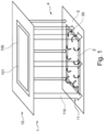
- FIG 1 is a schematic perspective view of an embodiment of the kitchen arrangement 4 according to the invention.
- the kitchen arrangement 4 comprises a hob 2 and an extractor hood 1.
- the extractor hood 1 consists of an extraction device 11 and a ceiling fan unit 10.
- the extraction device 11 is in Figure 1 only the suction opening 110 is visible.
- the ceiling fan unit 10 is Figure 1 only the underside 104 of the ceiling fan unit 10 with the air outlet opening 100 provided therein is shown.
- the suction device 11 is installed in a work surface 3.
- a recess 30 is installed in the work surface.
- the air outlet opening 100 is a circumferential gap that surrounds the central surface 103.
- the central surface 103 has a rectangular shape.
- the air outlet opening 100 thus describes a rectangular shape that surrounds the central surface 103.
- the suction opening 110 of the suction device 11 extends in the embodiment shown along the four edges of the rectangular cooking surface 2.
- the suction opening 110 runs directly along the edges of the cooking surface 2.
- the Size, in particular the width and depth of the outer edge of the suction opening 110 is smaller than the size, in particular the width and depth of the outer edge of the air outlet opening 100 of the ceiling blower unit 10.
- air is discharged downwards via the air outlet opening 100.
- the air is preferably discharged via the entire air outlet opening 100 and thus forms a circumferential air curtain, which can also be referred to as a bell.
- the air curtain hits the worktop 3 outside the suction opening 110. Air is sucked downwards via the suction opening 110.
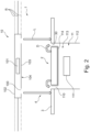
- the ceiling fan unit 10 has a housing 102 which has a cuboid shape.
- the height of the housing 102 is less than its width and depth.
- a fan 101 is accommodated in the housing 102.
- An air outlet opening 100 is made in the underside 104 of the ceiling fan unit 10 and thus in the underside of the housing 102.
- the air outlet opening 100 represents a gap that is spaced from the outer edges of the housing 102.
- the air outlet opening 100 is a circumferential opening that surrounds a central surface 103.
- the central surface 103 has a rectangular shape.
- the ceiling fan unit 10 is mounted in a room ceiling R.
- the housing 102 of the ceiling fan unit 10 is partially received in the room ceiling R and partially projects downwards beyond the underside of the room ceiling R.
- the dashed upper line shows another type of mounting of the ceiling fan unit 10.
- the ceiling blower unit 10 is attached to the underside of the ceiling R and the top of the housing 102 rests against the ceiling R.
- the dot-dash line indicates another embodiment.
- the ceiling blower unit 10 lies completely in the ceiling R.
- the underside 104 of the ceiling blower unit 10 and thus of the housing 102 lies in the plane of the underside of the ceiling R in this embodiment.
- Air is discharged downwards from the air outlet opening 100. Since the air outlet opening 100 represents a gap, the air is discharged as a continuous air curtain from the air outlet opening 100. The air preferably flows vertically downwards. The air thus hits a worktop 3, which is arranged below the ceiling fan unit 10.
- a recess 30 is made in the worktop 3.
- the recess 30 has a rectangular shape.
- the suction device 11 is arranged in this recess 30.
- the housing 112 of the suction device 11 is introduced into the recess 30.
- a suction fan 111 is arranged in the housing 112.
- the housing 112 has a suction opening 110 in the top.
- the suction opening 110 surrounds a central region 103 in which a receptacle 104 for a hob 2 is formed.
- the hob 2 is accommodated in the receptacle 104.
- the suction opening 110 is thus adjacent to the hob 2 and preferably surrounds it on all four edges. Air is sucked downwards through the suction opening 110 via the suction fan 111. In particular, fumes that arise when cooking on the hob 2 are sucked into the suction opening 110.
- the width and depth of the central surface 103 of the ceiling fan unit 10 is greater than the width and depth of the housing 112 of the suction device 11.
- the ceiling fan unit 10 is arranged above the suction device 11 in such a way that the air which is emitted from the air outlet opening 100 of the ceiling fan unit 10 strikes the outer edges of the suction device 11 and in particular the suction opening 110 offset outwards.
- the air which can be referred to as an air curtain, thus strikes the worktop 3 adjacent to the suction opening 110.
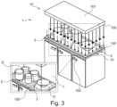
- FIG 3 a further embodiment of the kitchen arrangement 4 is shown.
- the air outlet opening 100 is introduced into the outer edge of the housing 102 of the ceiling fan unit 10.
- the shape of the central surfaces which in Figure 3 is not visible, is an elongated rectangle.
- the hob 2 which is arranged below the ceiling fan unit 10, has a square shape and is arranged so that it is off-center to the central surface of the ceiling fan unit 10.
- the air exiting from the air outlet opening 100 of the ceiling fan unit 10 hits the worktop 3 near three edges of the hob 2.
- the fourth edge in the Figure 3 the right edge, the air hits the hob 2 at a great distance.
- the extraction device 11 is in the embodiment according to Figure 3 designed so that the extraction opening 110 extends along three edges of the hob 2 and is spaced apart from the fourth edge of the hob 2.
- the air curtain that is emitted from the air outlet opening 100 impinges on the extraction opening 110 offset outwards.
- a vessel can be placed next to the hob 2 on the part of the worktop 3 that is surrounded by the air curtain L. Due to the surrounding air curtain L and the flow through which air is sucked into the extraction opening 110, vapors D that rise from the vessel or cooking vessels on the hob 2 are drawn downwards. This is shown in the detailed view of Figure 3 indicated.
- the present invention thus provides a solution by which fumes and in particular particles such as fat and water are encapsulated by an air curtain and can be reliably guided to an extraction opening near a hob.
- the extraction device is preferably arranged near the hob or worktop.
- the ceiling blower unit is arranged on the ceiling and preferably blows air out in the direction of the hob.
- the width of the extraction opening which can represent an extraction gap, is preferably less than 5 mm.
- an air curtain is created, which represents a laminar downward flow, which flows in the opposite direction to the enclosed flow, i.e. the upward vapors.
- the downward air flow is generated by an air outlet opening, which can be provided, for example, on a duct in the ceiling of the room.
- the air outlet opening is adapted to the external dimensions of the work surface system.
- An extraction opening which can also be referred to as an extraction duct and preferably has a width of less than 5cm and an undefined length, allows air to be sucked in downwards from the kitchen.
- the extraction duct is combined with the ceiling system, which is directed from the ceiling to the floor or the work surface.
- the cooking fumes are preferably extracted through an extraction duct near the hob.
- the flow rate of the air from the air outlet opening is preferably greater than the extraction flow with which air is sucked into the extraction opening. This ensures that an air bell is created, which leads to an efficient restriction of odors and small particles.
- the present invention has the particular advantage that a significant improvement in the detection rate can be achieved, even with high ceilings.
Landscapes
- Engineering & Computer Science (AREA)
- Chemical & Material Sciences (AREA)
- Combustion & Propulsion (AREA)
- Mechanical Engineering (AREA)
- General Engineering & Computer Science (AREA)
- Ventilation (AREA)
Description
- Die vorliegende Erfindung betrifft eine Küchenanordnung mit einem zumindest einem Dunstabzug.
- Zum Reinigen von Dünsten und Wrasen, die beim Kochen entstehen, ist es bekannt über einem Kochfeld eine Dunstabzugshaube anzuordnen, die die Dünste und Wrasen einsaugt.
- Aus der
DE 33 04 262 A1 ist eine Dunstabzugshaube mit einem den Luftstrom begrenzenden Luftvorhang bekannt. Bei dieser Dunstabzugshaube werden die nach oben steigenden Dünste und Wrasen durch einen Luftvorhang nach außen begrenzt. Die Strömung der Dünste und Wrasen wird nach oben in die Dunstabzugshaube eingesaugt. - Ein Nachteil dieser Art des Dunstabzuges besteht darin, dass die zu der Absaugöffnung nach oben gerichtete Ansaugströmung der Dünste und Wrasen und der nach unten gerichtete Luftvorhang zu Turbulenzen führen und damit die Erfassungsrate der Dünste und Wrasen verringert wird.
- In der
FR3012579A1 EP1696180A2 ist jeweils eine Dunstabzugshaube beschrieben, die oberhalb einer Kochstelle angeordnet ist und von der Ebene der Kochstelle aus ein Luftschleier nach oben in Richtung der Dunstabzugshaube ausgegeben wird. - Zudem ist in der
US 2016 009121 1A1 ein Einblasventilationssystem beschrieben, das sowohl für die Luftzufuhr als auch zum Absaugen von Luft dient. Hierzu ist eine oberhalb eines Kochfeldes angeordnete Vorrichtung vorgesehen, über die Luft an der Vorderseite ausgegeben wird und auf einen hinter dem Kochfeld ausfahrbaren Absaugkanal und insbesondere auf die in dessen Vorderseite vorgesehene Absaugöffnung gerichtet ist. Eine solche Vorrichtung ist auch in derJPS58104430A - Auch bei diesem System ist die Erfassungsrate der Dünste gering, da Dünste weiterhin von deren Entstehungsort nach vorne und zu den Seiten entweichen können.
- Aufgabe der vorliegenden Erfindung ist es daher eine Lösung zu schaffen, mittels derer die Erfassungsrate von Dünsten und Wrasen bei einfachem Aufbau gesteigert werden kann.
- Die Erfindung betrifft eine Küchenanordnung mit den Merkmalen des Anspruchs 1.
- Als Dunstabzug wird hierbei eine Vorrichtung bezeichnet, die zum Einsaugen von Dünsten und Wrasen, die beim Kochen auf einem Kochfeld entstehen, dient. Der Dunstabzug umfasst erfindungsgemäß eine Absaugvorrichtung sowie eine Decken-Gebläseeinheit, die auch als Zulufteinheit bezeichnet werden kann. Vorzugsweise weist die Absaugvorrichtung mindestens ein Filterelement auf, über das die eingesaugten Dünste und Wrasen, die im Folgenden einfach als Dünste oder als Luft bezeichnet werden, gereinigt werden. Die Absaugvorrichtung weist mindestens ein Sauggebläse auf, durch das Luft über die mindestens eine Absaugöffnung eingesaugt wird. Das Sauggebläse ist unterhalb der Absaugöffnung angeordnet. Als unterhalb der Absaugöffnung angeordnet wird ein Sauggebläse bezeichnet, das auf einer geringeren Höhe als die Absaugöffnung angeordnet, ist. In horizontaler Richtung kann das Sauggebläse zu der Absaugöffnung versetzt angeordnet sein. Durch die Anordnung des Sauggebläses unterhalb der Absaugöffnung wird Luft über die Absaugöffnung nach unten eingesaugt. Die Absaugöffnung liegt vorzugsweise in der Horizontalen. Es liegt aber auch im Rahmen der Erfindung, dass die Absaugöffnung zu der Horizontalen geneigt liegt. Vorzugsweise liegt die Absaugöffnung in der Ebene der Oberseite des Kochfeldes. Es liegt aber auch im Rahmen der Erfindung, dass die Absaugöffnung zu der Oberseite des Kochfeldes nach oben oder unten versetzt liegt. Die Absaugvorrichtung kann eine oder mehrere Absaugöffnungen aufweisen. Im Folgenden wird im Wesentlich Bezug genommen auf eine Absaugvorrichtung mit einer Absaugöffnung. Die Absaugöffnung kann in dem Kochfeld oder zu diesem benachbart liegen. Insbesondere kann die Absaugöffnung beispielsweise hinter dem Kochfeld oder in der Mitte des Kochfeldes angeordnet sein. Es liegt auch im Rahmen der Erfindung, dass zwei Absaugöffnungen vorgesehen sind, die sich jeweils entlang eines Seitenrandes des Kochfeldes erstrecken. Besonders bevorzug erstreckt sich die Absaugöffnung vollständig entlang der Ränder des Kochfeldes, das heißt umgibt das Kochfeld.
- Die Decken-Gebläseeinheit des erfindungsgemäßen Dunstabzuges weist zumindest ein Gebläse und zumindest eine Luftauslassöffnung auf. Die Decken-Gebläseeinheit ist erfindungsgemäß oberhalb der Absaugvorrichtung angeordnet. Die Decken-Gebläseeinheit stellt eine zu der Absaugvorrichtung separate Einheit dar. Allerdings können die Decken-Gebläseeinheit und die Absaugvorrichtung gemäß einer Ausführungsform gemeinsam angesteuert werden.
- Insbesondere ist die Decken-Gebläseeinheit vorzugsweise in oder an einer Raumdecke oberhalb der Absaugvorrichtung angeordnet. Als Raumdecke wird die Decke des Raumes bezeichnet, in dem der Dunstabzug betrieben wird. Die Raumdecke ist daher vorzugsweise die Decke einer Küche. Die Luftauslassöffnung kann einen Spalt in einem Gehäuse der Decken-Gebläseeinheit sein. Es ist aber auch möglich, dass die kann die Luftauslassöffnung durch die Unterseite eines nach unten offenen Kanals in der Raumdecke gebildet wird. Alternativ oder zusätzlich kann die Luftauslassöffnung auch durch einen Schlitz oder mehrere Durchlässe in einer Luftleitung, die ein Rohr darstellen kann, gebildet sein. Die Luftauslassöffnung ist in der Unterseite der Absaugvorrichtung angeordnet. Insbesondere kann die Luftauslassöffnung in die Unterseite eines Gehäuses eingebracht sein. In dem Fall, in dem die Luftauslassöffnung durch einen Schlitz oder Durchlässe in Luftleitung oder durch die Unterseite eines nach unten offenen Kanals gebildet ist, kann die Luftleitung beziehungsweise der Kanal an der Unterseite des Gehäuses vorgesehen sein, oder durch die Unterseite des Gehäuses hindurchragen. Es ist aber auch möglich, dass die Decken-Gebläseeinheit kein Gehäuse aufweist, sondern nur ein Gebläse, das mit dem Kanal oder der Luftleitung verbunden ist, an dem beziehungsweise an der die Luftauslassöffnung liegt.
- Durch die Luftauslassöffnung wird ein nach unten gerichteter Luftvorhang ausgegeben. Der Luftvorhang ist vorzugsweise durchgehend. Aus diesem Grund stellt die Luftauslassöffnung vorzugsweise einen durchgehenden Schlitz oder Spalt dar. Der Luftvorhang begrenzt erfindungsgemäß den Raum unter der Decken-Gebläseeinheit an zumindest drei Seiten. Der Raum unter der Decken-Gebläseeinheit ist vorzugsweise der Raum oberhalb des Kochfeldes. Die Luftauslassöffnung erstreckt sich somit vorzugsweise zumindest entlang der Breitenrichtung in vorderen Bereich der Unterseite der Decken-Gebläseeinheit und entlang der Tiefenrichtung an zwei seitlichen Bereichen der Unterseite der Decken-Gebläseeinheit. Sofern der Luftvorhang den Raum unterhalb der Decken-Gebläseeinheit zu allen Seiten begrenzt, erstreckt sich die Luftauslassöffnung zudem in der Breitenrichtung im hinteren Bereich der Unterseite der Decken-Gebläseeinheit. In diesem Fall wird die Luftauslassöffnung auch als periphere Luftauslassöffnung bezeichnet. Die Begrenzung des Raumes unterhalb der Decken-Gebläseeinheit zu drei Seiten ist dann bevorzugt, wenn das Kochfeld vor einer Raumwand angeordnet ist. In diesem Fall wird die vierte Seite des Raumes unterhalb der Decken-Gebläseeinheit durch die Raumwand begrenzt.
- Die Decken-Gebläseeinheit weist vorzugsweise eine Quaderform auf und die Unterseite der Decken-Gebläseeinheit stellt eine ebene Fläche dar.
- Richtungsangaben, wie oben und unten beziehen sich, soweit nicht anders angegeben, auf den Dunstabzug im montierten Zustand, in dem die Decken-Gebläseeinheit oberhalb eines Kochfeldes an oder in einer Raumdecke befestigt ist.
- Indem erfindungsgemäß eine Decken-Gebläseeinheit vorgesehen ist, durch die ein nach unten gerichteter Luftvorhang erzeugt wird, der den Raum unterhalb der Decken-Gebläseeinheit zumindest an drei Seiten begrenzt und vorzugsweise vollständig, das heißt an vier Seiten begrenzt, und der Dunstabzug zudem unterhalb der Decken-Gebläseeinheit eine Absaugvorrichtung aufweist, über die Luft nach unten abgesaugt wird, kann eine Reihe von Vorteilen erzielt werden. Insbesondere werden die Dünste und damit die darin enthaltenen Partikel eingekapselt. Ein Entweichen zu den Seiten wird durch den Luftvorhang verhindert, Zudem werden, da der Luftvorhang nach unten gerichtet ist und zudem die Luft über die Absaugöffnung nach unten abgesaugt wird, die Dünste zu der Absaugöffnung geleitet und der Ansaugstrom, der durch das Sauggebläse erzeugt wird, durch den nach unten gerichteten Luftstrom aus der Decken-Gebläseeinheit unterstützt. Schließlich wird durch den Luftstrom aus der Decken-Gebläseeinheit eine laminare Luftströmung erzeugt. Diese Luftströmung stellt eine unidirektionale Strömung dar, die aus kleinen Luftströmungen besteht, die sich mit gleicher Geschwindigkeit in einer parallelen Richtung bewegen und eine Luftströmung ohne Turbulenzen erzeugt. Durch diese laminare Luftströmung werden Partikel in der Nähe des Luftstroms mitgerissen und somit in die Richtung auf die Absaugöffnung gelenkt. Der Luftvorhang bildet somit eine Glocke oder Luftglocke über dem Kochfeld und führt zu einer verbesserten Erfassungsrate der Dünste.
- Gemäß einer Ausführungsform stellt die Luftauslassöffnung einen Spalt in der Unterseite der Decken-Gebläseeinheit dar, der sich zumindest teilweise um eine mittlere Fläche der Unterseite herum erstreckt. Besonders bevorzugt weist die Decken-Gebläseeinheit ein Gehäuse auf, in der in der Unterseite der Spalt eingebracht ist. Der Spalt stellt einen Spalt dar, der eine mittlere Fläche der Unterseite der Decken-Gebläseeinheit zumindest teilweise umgibt. Oberhalb der mittleren Fläche kann das Gebläse der Decken-Gebläseeinheit angeordnet sein. Die Größe der mittleren Fläche ist vorzugsweise größer als die Fläche eines unterhalb der Decken-Gebläseeinheit angeordneten Kochfeldes. Der Spalt ist vorzugsweise zu den Rändern der Unterseite der Decken-Gebläseeinheit beabstandet in die Unterseite der Decken-Gebläseeinheit eingebracht. Vorzugsweise stellt die mittlere Fläche eine geschlossene, das heißt luftundurchlässige Fläche dar.
- Indem die Luftauslassöffnung einen Spalt in der Unterseite der Decken-Gebläseeinheit darstellt, der sich zumindest teilweise um eine mittlere Fläche der Unterseite herum erstreckt, kann eine zuverlässige Ausgabe der Zuluft nach unten gewährleistet werden.
- Gemäß einer Ausführungsform stellt die mittlere Fläche eine rechteckige Fläche der Unterseite der Decken-Gebläseeinheit dar und der Spalt erstreckt sich entlang der vier Kanten der rechteckigen mittleren Fläche. Vorzugsweise stellt der Spalt bei dieser Ausführungsform einen durchgehenden Spalt dar. Bei dieser Ausführungsform kann über die Luftauslassöffnung ein durchgehender Luftvorhang ausgegeben werden, der den Raum unter der Decken-Gebläseeinheit umgibt und diesen damit abschließt. Indem die mittlere Fläche, um den sich der Spalt erstreckt eine rechteckige Fläche ist, kann der Raum über eine Kochfeld, das in der Regel ebenfalls eine rechteckige Form aufweist, durch den Luftvorhang zu den Seiten begrenzt werden. Da die Luft über die Luftauslassöffnung in Form eines Spaltes nach unten abgegeben wird, werden zudem die Dünste, die von dem Kochfeld aufsteigen, zumindest an den Rändern des Raumes durch den Luftvorhang nach unten geleitet und somit zu der unterhalb der Decken-Gebläseeinheit liegenden Absaugvorrichtung geleitet.
- Gemäß einer weiteren Ausführungsform wird die Luftauslassöffnung durch eine Unterseite eines nach unten offenen Kanals gebildet. Auch bei dieser Ausführungsform kann die Luftauslassöffnung als Spalt bezeichnet werden. Zudem weist auch bei dieser Ausführungsform der Kanal vorzugsweise einen in einen rechteckigen Verlauf auf. Die mittlere Fläche, die von dem Kanal beziehungsweise dem Spalt umgeben ist, ist bei dieser Ausführungsform eine Teilfläche der Raumdecke.
- Gemäß einer Ausführungsform stellt die Absaugöffnung der Absaugvorrichtung einen umlaufenden Spalt dar, der sich zumindest teilweise um einen rechteckigen mittleren Bereich der Absaugvorrichtung herum erstreckt. Vorzugswiese erstreckt sich der umlaufende Spalt vollständig um den rechteckigen mittleren Bereich der Absaugvorrichtung. Indem die Absaugöffnung, einen zumindest teilweise umlaufenden Spalt darstellt, können Dünste besonders effizient eingesaugt werden. Insbesondere können Dünste, die auf unterschiedlichen Kochzonen eines Kochfeldes entstehen in unmittelbarer Nähe zu dem Entstehungsort abgesaugt werden. Insbesondere bei einer Ausführungsform, bei der auch die Luftauslassöffnung einen umlaufenden Spalt um eine rechteckige mittlere Fläche darstellt, ist es vorteilhaft, dass die Form der Absaugöffnung der Form der Luftauslassöffnung angepasst ist. Hierdurch kann eine gezielte Luftströmung eingestellt werden, die ein zuverlässiges Einsaugen der Dünste erlaubt.
- Gemäß einer bevorzugten Ausführungsform stellt der mittlere Bereich der Absaugvorrichtung eine Aufnahme für zumindest ein Kochfeld dar. Der mittlere Bereich kann daher beispielsweise eine Aussparung in der Absaugvorrichtung darstellen, in die das Kochfeld eingesetzt werden kann. Alternativ kann der mittlere Bereich bei dieser Ausführungsform auch eine Wanne darstellen, in die das Kochfeld aufgenommen werden kann. Der mittlere Bereich kann beispielsweise der mittlere Teil der Oberseite eines Gehäuses der Absaugvorrichtung darstellen. Indem das Kochfeld im mittleren Bereich aufgenommen werden kann, um den sich die als Spalt ausgebildete Absaugöffnung herum erstreckt, kann ein zuverlässiges Absaugen zu den Rändern des Kochfeldes gewährleistet werden.
- Gemäß einer Ausführungsform weist die Absaugöffnung, die durch einen Spalt gebildet wird, eine Breite von maximal 5cm auf. Eine solche schmale Absaugöffnung ist bei dem erfindungsgemäßen Dunstabzug möglich, da das Ansaugen über die Absaugöffnung durch den Luftvorhang, der aus der Luftauslassöffnung ausgegeben wird, unterstützt wird. Durch die schmale Absaugöffnung kann zudem die Größe der Decken-Gebläseeinheit geringer dimensioniert werden. Vorzugsweise ist die Decken-Gebläseeinheit so dimensioniert, dass der über die Luftauslassöffnung ausgegebene Luftvorhang außerhalb Absaugöffnung, die vorzugsweise um das Kochfeld umlaufend vorgesehen ist, auf der Ebene des Kochfeldes, beispielsweise auf einer Arbeitsplatte auftrifft. Indem der Absaugspalt vorzugsweise eine geringe Breite, insbesondere von maximal 5cm aufweist, kann damit der Luftvorhang in der Nähe des Kochfeldes auftreffen und die Decken-Gebläseeinheit kann eine geringere Größe, insbesondere eine geringere Breite und Tiefe aufweisen.
- Gemäß einer bevorzugten Ausführungsform ist die durch die Luftauslassöffnung begrenzte mittlere Fläche der Decken-Gebläseeinheit größer als der durch die Absaugöffnung begrenzte mittlere Bereich der Absaugvorrichtung. Vorzugsweise sind die Decken-Gebläseeinheit und die Absaugvorrichtung dabei so angeordnet, dass die Luftauslassöffnung in senkrechter Projektion nach unten an allen Stellen außerhalb der Absaugöffnung der Absaugvorrichtung liegt. Besonders bevorzugt entspricht die Form der Luftauslassöffnung der Form der Absaugöffnung. Insbesondere können diese jeweils durch einen Spalt gebildet sein, der in seiner Längserstreckung ein Rechteck beschreibt. Indem die mittlere Fläche der der Decken-Gebläseeinheit größer als der durch die Absaugöffnung begrenzte mittlere Bereich der Absaugvorrichtung und die Luftauslassöffnung vorzugsweise in senkrechter Projektion außerhalb der Absaugöffnung liegt, kann sichergestellt werden, dass die Absaugöffnung und die Luftauslassöffnung sich nicht überdecken und dadurch ein unmittelbares Einsaugen von Luft von der Luftauslassöffnung in die Absaugöffnung verhindert werden kann. Ein solches unmittelbares Einsaugen würde nämlich zu einer erhöhten Anforderung an das Gebläse der Absaugvorrichtung führen, da dieses ein größeres Luftvolumen bewegen müsste, als beim reinen Absaugen von Luft, die innerhalb des begrenzenden Luftvorhangs vorliegt.
- Gemäß einer Ausführungsform ist die Decken-Gebläseeinheit so ausgelegt, dass die Ausblasgeschwindigkeit von Luft über die mindestens eine Luftauslassöffnung im Bereich von 0,5 m/s bis 8 m/s, vorzugsweise zwischen 2 und 6 m/s liegt. Als Ausblasgeschwindigkeit wird die Geschwindigkeit bezeichnet, die die Luft nach dem Passieren der Luftauslassöffnung aufweist. Die Ausblasgeschwindigkeit kann durch die geeignete Auslegung des Gebläses der Decken-Gebläseeinheit und durch die Größe der Luftauslassöffnung, insbesondere die Breite des Spaltes, der die Luftauslassöffnung vorzugsweise bildet, eingestellt werden. Durch diese Ausblasgeschwindigkeiten kann das Aufbauen eines Luftvorhangs gewährleistet werden, der zuverlässig den Raum unter der Decken-Gebläseeinheit und damit oberhalb des Kochfeldes begrenzt. Durch das Einstellen solcher Ausblasgeschwindigkeiten wird zum einen verhindert, das Dünste zu den Seiten entweichen. Zum anderen werden durch diese Ausblasgeschwindigkeiten Dünste in der Nähe des Luftvorhangs nach unten gezogen und damit in Richtung der Absaugöffnung geleitet. Zudem ist diese Ausblasgeschwindigkeit vorzugsweise größer als die Einsauggeschwindigkeit mit der Luft in die Absaugöffnung der Absaugvorrichtung eingesaugt wird. Somit kann die Ausbildung des Luftvorhangs insbesondere in der Form einer umgebenden Glocke gewährleistet werden.
- Gemäß einer Ausführungsform ist die Decken-Gebläseeinheit in einer Raumdecke integrierbar. Bei dieser Ausführungsform weist die Decken-Gebläseeinheit vorzugsweise an deren Seitenwänden oder an der Unterseite Befestigungsmittel auf, über die die Decken-Gebläseeinheit an einer Öffnung in der Raumdecke befestigt werden kann. Diese Ausführungsform ist besonders bevorzugt, da hierdurch die Decken-Gebläseeinheit nur um einen geringen Betrag über die Raumdecke nach unten übersteht oder vollständig in der Raumdecke aufgenommen ist und lediglich die Unterseite der Decken-Gebläseeinheit mit der Unterseite der Raumdecke bündig ist. Hierdurch wird der optische Eindruck des Dunstabzuges verbessert, da die Decken-Gebläseeinheit für den Benutzer nicht oder nur geringfügig sichtbar ist. Zudem können auch die Absaugvorrichtung und insbesondere die Absaugöffnung mit der Oberfläche einer Arbeitsplatte bündig sein oder zu dieser nach unten versetzt sein, so dass auch die Absaugvorrichtung für den Benutzer kaum sichtbar ist.
- Die Decken-Gebläseeinheit kann aber auch mit der Oberseite an einer Raumdecke befestigbar sein. Hierzu kann die Decken-Gebläseeinheit an der Oberseite oder den Seitenwänden Befestigungsmittel aufweisen. Die Decken-Gebläseeinheit wird dabei so an der Raumdecke befestigt, dass diese mit deren Oberseite an der Raumdecke anliegt. Die Decken-Gebläseeinheit weist vorzugsweise eine geringere Höhe als Breite und Tiefe auf. Somit hierbei der Überstand der Decken-Gebläseeinheit über die Unterseite der Raumdecke minimiert und dadurch das optische Erscheinungsbild verbessert.
- Gemäß einer Ausführungsform weist die Decken-Gebläseeinheit ein Gehäuse auf. In der Unterseite des Gehäuses ist vorzugsweise die Luftauslassöffnung der Decken-Gebläseeinheit eingebracht. Das Gebläse der Decken-Gebläseeinheit kann hierbei in dem Gehäuse der Decken-Gebläseeinheit angeordnet sein. Alternativ kann das Gebläse mit dem Gehäuse verbunden sein und damit außerhalb des Gehäuses liegen. Auch bei dieser Ausführungsform liegt das Gebläse aber vorzugsweise in oder oberhalb der Raumdecke und ist somit für den Benutzer nicht sichtbar.
- Gemäß einer Ausführungsform weist die Absaugvorrichtung ein Gehäuse auf. In der Oberseite des Gehäuses ist hierbei die Absaugöffnung der Absaugvorrichtung eingebracht. Das Sauggebläse kann in dem Gehäuse der Absaugvorrichtung aufgenommen sein oder mit diesem Gehäuse verbunden sein.
- Die Absaugvorrichtung des Dunstabzuges kann eine Absaugöffnung aufweisen, die sich entlang einer Kante, das heißt eines Randes des Kochfeldes erstreckt oder sich entlang der Mitte der Breite des Kochfeldes erstreckt. Auch bei diesen Arten von Absaugvorrichtung kann mittels der weiterhin in dem Dunstabzug vorgesehenen separaten Decken-Gebläseeinheit zuverlässig ein Luftvorhang vorzugsweise um das Kochfeld herum gebildet werden und damit die Dünste abgeschirmt werden.
- Erfindungsgemäß erstreckt sich die Absaugöffnung zumindest entlang dreier Kanten des Kochfeldes. Gemäß einer Ausführungsform erstrekt sich die Absaugöffnung entlang vier Katen des Kochfeldes. Durch diese Anordnung der Absaugöffnung der Absaugvorrichtung können durch den Luftvorhang, der aus der Decken-Gebläseeinheit ausgegeben wird, die Dünste zuverlässig in die Nähe der Absaugöffnung gelenkt werden.
- Gemäß einer Ausführungsform liegt die Absaugöffnung der Absaugvorrichtung in einer Aussparung einer Arbeitsplatte eines Küchenschrankes. Hierbei ist die Aussparung in der Arbeitsplatte größer als die Abmessungen des Kochfeldes. Somit kann eine um das Kochfeld umlaufende Absaugöffnung gebildet werden.
- Gemäß einer bevorzugten Ausführungsform liegt die Luftauslassöffnung in vertikaler Projektion nach unten außerhalb der Absaugöffnung der Absaugvorrichtung. Insbesondere bei einer Absaugöffnung, die durch einen rechteckig verlaufenden Spalt gebildet wird, liegt die Luftauslassöffnung, die vorzugsweise ebenfalls einen rechteckige Verlauf aufweist, in der Projektion vollständig außerhalb der Absaugöffnung.
- Die vorliegende Erfindung wird im Folgenden erneut unter Bezugnahme auf die beiliegenden Zeichnungen beschrieben. Es zeigen:
- Figur 1:
- eine schematische Perspektivansicht einer Ausführungsform der erfindungsgemäßen Küchenanordnung;
- Figur 2:
- eine schematische Schnittansicht einer Ausführungsform der erfindungsgemäßen Küchenanordnung; und
- Figur 3:
- eine schematische Perspektivansicht einer weiteren Ausführungsform der erfindungsgemäßen Küchenanordnung.
- In
Figur 1 ist eine schematische Perspektivansicht einer Ausführungsform der erfindungsgemäßen Küchenanordnung 4 gezeigt. Die Küchenanordnung 4 umfasst ein Kochfeld 2 und einen Dunstabzug 1. Der Dunstabzug 1 besteht aus einer Absaugvorrichtung 11 und einer Decken-Gebläseeinheit 10. Von der Absaugvorrichtung 11 ist inFigur 1 nur die Absaugöffnung 110 sichtbar. Von der Decken-Gebläseeinheit 10 ist inFigur 1 nur die Unterseite 104 der Decken-Gebläseeinheit 10 mit der darin vorgesehenen Luftauslassöffnung 100 gezeigt. Die Absaugvorrichtung 11 ist in eine Arbeitsfläche 3 eingebracht. Hierzu ist in die Arbeitsfläche eine Aussparung 30 eingebracht. - Die Luftauslassöffnung 100 ist in der gezeigten Ausführungsform ein umlaufender Spalt, der die mittige Fläche 103 umgibt. Die mittige Fläche 103 weist eine rechteckige Form auf. Somit beschreibt die Luftauslassöffnung 100 eine rechteckige, die mittige Fläche 103 umgebenden Form.
- Die Absaugöffnung 110 der Absaugvorrichtung 11 erstreckt sich bei der gezeigten Ausführungsform entlang der vier Kanten des rechteckigen Kochfeldes 2. Die Absaugöffnung 110 verläuft unmittelbar an den Kanten des Kochfeldes 2 entlang. Die Größe, insbesondere die Breite und Tiefe des äußeren Randes der Absaugöffnung 110 ist geringer als die Größe, insbesondere Breite und Tiefe des äußeren Randes der Luftauslassöffnung 100 der Decken-Gebläseeinheit 10.
- Wie in
Figur 1 schematisch gezeigt, wird über die Luftauslassöffnung 100 Luft nach unten ausgegeben. Die Luft wird vorzugsweise über die gesamte Luftauslassöffnung 100 ausgegeben und bildet somit einen umlaufenden Luftvorhang, der auch als Glocke bezeichnet werden kann. Der Luftvorhang trifft bei der gezeigten Ausführungsform außerhalb der Absaugöffnung 110 auf die Arbeitsplatte 3 auf. Über die Absaugöffnung 110 wird Luft nach unten abgesaugt. - In der
Figur 2 ist eine schematische Schnittansicht einer Ausführungsform der Küchenanordnung 4 gezeigt. In dieser Ausführungsform weist die Decken-Gebläseeinheit 10 ein Gehäuse 102 auf, das eine Quaderform aufweist. Die Höhe des Gehäuses 102 ist geringer als dessen Breite und Tiefe. In dem Gehäuse 102 ist ein Gebläse 101 aufgenommen. Dieses ist inFigur 2 nur schematisch gezeigt. In der Unterseite 104 der Decken-Gebläseeinheit 10 und damit in der Unterseite des Gehäuses 102 ist eine Luftauslassöffnung 100 eingebracht. In der gezeigten Ausführungsform stellt die Luftauslassöffnung 100 einen Spalt dar, der zu den äußeren Kanten des Gehäuses 102 beabstandet ist. Die Luftauslassöffnung 100 ist eine umlaufende Öffnung, die eine mittige Fläche 103 umgibt. Die mittige Fläche 103 weist eine rechteckige Form auf. Die Decken-Gebläseeinheit 10 ist in der gezeigten Ausführungsform in einer Raumdecke R montiert. Insbesondere ist das Gehäuse 102 der Decken-Gebläseeinheit 10 teilweise in die Raumdecke R aufgenommen und ragt zum Teil über die Unterseite der Raumdecke R nach unten hinaus. Mit der gestrichelten oberen Linie ist eine andere Art der Montage der Decken-Gebläseeinheit 10 gezeigt. Bei dieser Ausführungsform ist die Decken-Gebläseeinheit 10 an der Unterseite der Raumdecke R befestigt und liegt mit der Oberseite des Gehäuses 102 an der Raumdecke R an. Mit der strichpunktierten Linie ist eine weitere Ausführungsform andeutet. Bei dieser Ausführungsform liegt die Decken-Gebläseeinheit 10 vollständig in der Raumdecke R. Die Unterseite 104 der Decken-Gebläseeinheit 10 und damit des Gehäuses 102 liegt in dieser Ausführungsform in der Ebene der Unterseite der Raumdecke R. - Aus der Luftauslassöffnung 100 wird Luft nach unten ausgegeben. Da die Luftauslassöffnung 100 einen Spalt darstellt, wird die Luft als durchgehender Luftvorhang aus der Luftauslassöffnung 100 ausgegeben. Die Luft strömt vorzugsweise vertikal nach unten. Die Luft trifft somit auf eine Arbeitsplatte 3, die unterhalb der Decken-Gebläseeinheit 10 angeordnet ist, auf. In der Arbeitsplatte 3 ist eine Aussparung 30 eingebracht. Die Aussparung 30 weist eine rechteckige Form auf. In dieser Aussparung 30 ist die Absaugvorrichtung 11 angeordnet. Insbesondere ist bei der gezeigten Ausführungsform das Gehäuse 112 der Absaugvorrichtung 11 in die Aussparung 30 eingebracht. In dem Gehäuse 112 ist ein Sauggebläse 111 angeordnet. Das Gehäuse 112 weist in der gezeigten Ausführungsform in der Oberseite eine Absaugöffnung 110 auf. Die Absaugöffnung 110 umgibt einen mittleren Bereich 103, in der eine Aufnahme 104 für ein Kochfeld 2 gebildet ist. In die Aufnahme 104 ist das Kochfeld 2 aufgenommen. Somit liegt die Absaugöffnung 110 zu dem Kochfeld 2 benachbart und umgibt dieses vorzugsweise an allen vier Kanten. Über das Sauggebläse 111 wird Luft durch die Absaugöffnung 110 nach unten abgesaugt. Insbesondere werden Dünste, die beim Kochen auf dem Kochfeld 2 entstehen in die Absaugöffnung 110 eingesaugt.
- Die Breite und Tiefe der mittigen Fläche 103 der Decken-Gebläseeinheit 10 ist größer als die Breite und Tiefe des Gehäuses 112 der Absaugvorrichtung 11. Zudem ist die Decken-Gebläseeinheit 10 so oberhalb der Absaugvorrichtung 11 angeordnet, dass die Luft, die von der Luftauslassöffnung 100 der Decken-Gebläseeinheit 10 ausgegeben wird, zu der den äußeren Kanten der Absaugvorrichtung 11 und insbesondere der Absaugöffnung 110 nach außen versetzt auftrifft. Die Luft, die als Luftvorhang bezeichnet werden kann, trifft somit auf der Arbeitsplatte 3 zu der Absaugöffnung 110 benachbart auf.
- In
Figur 3 ist eine weitere Ausführungsform der Küchenanordnung 4 gezeigt. In dieser Ausführungsform ist die Luftauslassöffnung 100 in dem äußeren Rand des Gehäuses 102 der Decken-Gebläseeinheit 10 eingebracht. Die Form der mittigen Flächen, die inFigur 3 nicht sichtbar ist, ist ein längliches Rechteck. Das Kochfeld 2, das unterhalb der Decken-Gebläseeinheit 10 angeordnet ist, weist eine quadratische Form auf und ist so angeordnet, dass dieses zu der mittigen Fläche der Decken-Gebläseeinheit 10 außermittig liegt. Somit trifft bei der gezeigten Ausführungsform die Luft, die aus der Luftauslassöffnung 100 der Decken-Gebläseeinheit 10 austritt, in der Nähe von drei Rändern des Kochfeldes 2 auf der Arbeitsplatte 3 auf. Zu dem vierten Rand, in derFigur 3 dem rechten Rand, trifft die Luft in einem großen Abstand zu dem Kochfeld 2 auf. Die Absaugvorrichtung 11 ist bei der Ausführungsform nachFigur 3 so ausgelegt, dass die Absaugöffnung 110 sich entlang von drei Rändern des Kochfeldes 2 anliegend und zu dem vierten Rand des Kochfeldes 2 beabstandet erstreckt. Auch bei dieser Ausführungsform trifft der Luftvorhang, der aus der Luftauslassöffnung 100 ausgegeben wird, zu der Absaugöffnung 110 nach außen versetzt auf. - Wie in der Detailansicht von
Figur 3 gezeigt, kann neben dem Kochfeld 2 auf dem Teil der Arbeitsplatte 3, die von dem Luftvorhang L umgeben ist, ein Gefäß abgestellt werden. Durch den umgebenden Luftvorhang L und die Strömung, durch die Luft in die Absaugöffnung 110 eingesaugt wird, werden Dünste D, die von dem Gefäß oder von Gargefäßen auf dem Kochfeld 2 nach oben steigen, nach unten gezogen. Dies ist in der Detailansicht vonFigur 3 angedeutet. - Mit der vorliegenden Erfindung wird somit eine Lösung geschaffen, durch die Dünste und insbesondere Partikel, wie Fett und Wasser, durch einen Luftvorhang eingekapselt werden und zuverlässig zu einer Absaugöffnung in der Nähe eines Kochfeldes geleitet werden können. Die Absaugvorrichtung ist vorzugsweise in der Nähe des Kochfeldes oder der Arbeitsplatte angeordnet. Die Decken-Gebläseeinheit ist an der Raumdecke angeordnet und bläst vorzugsweise Luft in Richtung des Kochfeldes aus. Vorzugsweise ist die Breite der Absaugöffnung, die einen Absaugspalt darstellen kann, geringer als 5mm.
- Insbesondere wird ein Luftvorhang, der eine laminare nach unten gerichtete Strömung darstellt, erzeugt, der zu der eingeschlossenen Strömung, das heißt den nach oben gerichteten Dünsten, in entgegengesetzter Richtung strömt.
- Mit der vorliegenden Erfindung ist es daher möglich die gesamten Kochdünste einfangen zu können. Hierbei wird ein kombinierter Effektes von Absaugen und Zuführen von Luft genutzt, der ein gutes Eingrenzen und Führen der Dünste von der Decken-Gebläseeinheit, die auch als Deckensystem bezeichnet werden kann, zu der Absaugvorrichtung, die auch als Arbeitsflächensystem bezeichnet werden kann. Beide, das Deckensystem und das Arbeitsflächensystem sind sehr unauffällig.
- Der nach unten gerichtete Luftstrom wird erzeugt durch eine Luftauslassöffnung, die beispielsweise an einem Kanal in der Raumdecke vorgesehen sein kann. Die Luftauslassöffnung ist an die äußeren Abmessungen des Arbeitsflächensystems angepasst. Eine Absaugöffnung, die auch als Absaugkanal bezeichnet werden kann und vorzugsweise eine Breite von weniger als 5cm und eine nicht definierten Länge aufweist, erlaubt das Ansaugen von Luft aus der Küche nach unten. Der Absaugkanal ist mit dem Deckensystem kombiniert, das von der Raumdecke auf den Boden oder die Arbeitsfläche gerichtet ist. Die Kochdünste werden vorzugsweise durch einen Absaugkanal in der Nähe des Kochfeldes abgesaugt. Die Strömungsrate der Luft aus der Luftauslassöffnung ist vorzugsweise größer, als der Absaugstrom, mit dem Luft in die Absaugöffnung eingesaugt wird. Hierdurch wird gewährleistet, dass eine Luftglocke erzeugt wird, die zu einem effizienten Einschränken von Gerüchen und kleinen Partikeln führt.
- Die vorliegende Erfindung weist insbesondere den Vorteil auf, dass eine signifikante Verbesserung der Erfassungsrate, selbst bei hohen Raumdecken, erzielt werden kann.
-
- 1
- Dunstabzug
- 10
- Decken-Gebläseeinheit
- 100
- Luftauslassöffnung
- 101
- Gebläse
- 102
- Deckengehäuse
- 103
- mittlere Fläche
- 104
- Unterseite
- 11
- Absaugvorrichtung
- 110
- Absaugöffnung
- 111
- Sauggebläse
- 112
- Gehäuse
- 113
- mittlerer Bereich
- 114
- Aufnahme
- 2
- Kochfeld
- 3
- Arbeitsfläche
- 30
- Aussparung
- 4
- Küchenanordnung
- R
- Raumdecke
- D
- Dünste
- L
- Luftvorhang
Claims (11)
- Küchenanordnung bestehend aus einem Kochfeld und mindestens einem Dunstabzug (1), wobei der Dunstabzug (1) zum Absaugen von Luft aus einem Raum über dem Kochfeld (2) ausgebildet ist und eine Absaugvorrichtung (11) mit mindestens einer Absaugöffnung (110) und mindestens einem Sauggebläse (111) umfasst, wobei das Sauggebläse (111) unterhalb der Absaugöffnung (110) angeordnet ist und Luft über die Absaugöffnung (110) nach unten saugt, wobei der Dunstabzug (1) weiterhin eine Decken-Gebläseeinheit (10) aufweist, die oberhalb der Absaugvorrichtung (11) angeordnet ist, sowie mindestens ein Gebläse (101) und mindestens eine Luftauslassöffnung (100) in der Unterseite (104) der Decken-Gebläseeinheit (10) aufweist,
dadurch gekennzeichnet, dass durch die Decken-Gebläseeinheit (10) ein nach unten gerichteter Luftvorhang (L) ausgegeben wird, der den Raum unter der Decken-Gebläseeinheit (10) an zumindest drei Seiten begrenzt und die Absaugöffnung (110) sich zumindest entlang drei Kanten des Kochfeldes (2) erstreckt. - Küchenanordnung nach Anspruch 1, dadurch gekennzeichnet, dass die Luftauslassöffnung (100) einen Spalt in der Unterseite (104) der Decken-Gebläseeinheit (10) darstellt, der sich zumindest teilweise um eine mittlere Fläche (103) der Unterseite (104) herum erstreckt.
- Küchenanordnung nach Anspruch 2, dadurch gekennzeichnet, dass die mittlere Fläche (103) eine rechteckige Fläche der Unterseite (104) darstellt und der Spalt sich entlang der vier Kanten der rechteckigen mittleren Fläche (103) erstreckt.
- Küchenanordnung nach einem der Ansprüche 1 bis 3, dadurch gekennzeichnet, dass die Absaugöffnung (110) der Absaugvorrichtung (11) einen umlaufenden Spalt darstellt, der sich zumindest teilweise um einen rechteckigen mittleren Bereich (113) der Absaugvorrichtung (11) herum erstreckt.
- Küchenanordnung nach Anspruch 4, dadurch gekennzeichnet, dass der mittlere Bereich (113) der Absaugvorrichtung (11) eine Aufnahme (104) für zumindest ein Kochfeld (2) darstellt.
- Küchenanordnung nach einem der Ansprüche 4 oder 5, dadurch gekennzeichnet, dass der Spalt eine Breite von maximal 5cm aufweist.
- Küchenanordnung nach einem der Ansprüche 1 bis 6, dadurch gekennzeichnet, dass die durch die Luftauslassöffnung (100) begrenzte mittlere Fläche (103) der Decken-Gebläseeinheit (10) größer ist als der durch die Absaugöffnung (110) begrenzte mittlere Bereich (113) der Absaugvorrichtung (11).
- Küchenanordnung nach einem der Ansprüche 1 bis 7, dadurch gekennzeichnet, dass die Decken-Gebläseeinheit (10) so ausgelegt ist, dass die Ausblasgeschwindigkeit von Luft über die mindestens eine Luftauslassöffnung (100) im Bereich von zwischen 0,5 m/s und 8 m/s, vorzugsweise zwischen 2 m/s bis 6 m/s liegt.
- Küchenanordnung nach einem der Ansprüche 1 bis 8, dadurch gekennzeichnet, dass die Decken-Gebläseeinheit (10) in einer Raumdecke (R) integrierbar ist.
- Küchenanordnung nach einem der Ansprüche 1 bis 9, dadurch gekennzeichnet, dass die Absaugöffnung (110) sich entlang vier Kanten des Kochfeldes (2) erstreckt.
- Küchenanordnung nach einem der Ansprüche 1 bis 10, dadurch gekennzeichnet, dass die Luftauslassöffnung (100) in vertikaler Projektion nach unten außerhalb der Absaugöffnung (110) der Absaugvorrichtung (11) liegt.
Applications Claiming Priority (2)
| Application Number | Priority Date | Filing Date | Title |
|---|---|---|---|
| EP18290144 | 2018-12-21 | ||
| PCT/EP2019/086748 WO2020128013A1 (de) | 2018-12-21 | 2019-12-20 | Dunstabzug und küchenanordnung mit dunstabzug |
Publications (2)
| Publication Number | Publication Date |
|---|---|
| EP3899373A1 EP3899373A1 (de) | 2021-10-27 |
| EP3899373B1 true EP3899373B1 (de) | 2024-07-31 |
Family
ID=65003156
Family Applications (1)
| Application Number | Title | Priority Date | Filing Date |
|---|---|---|---|
| EP19828769.0A Active EP3899373B1 (de) | 2018-12-21 | 2019-12-20 | Küchenanordnung mit dunstabzug |
Country Status (3)
| Country | Link |
|---|---|
| EP (1) | EP3899373B1 (de) |
| CN (1) | CN113167482A (de) |
| WO (1) | WO2020128013A1 (de) |
Families Citing this family (1)
| Publication number | Priority date | Publication date | Assignee | Title |
|---|---|---|---|---|
| CN114110691B (zh) * | 2021-11-26 | 2023-12-05 | Tcl空调器(中山)有限公司 | 一种厨房通风系统及其控制方法 |
Family Cites Families (12)
| Publication number | Priority date | Publication date | Assignee | Title |
|---|---|---|---|---|
| JPS58104430A (ja) * | 1981-12-15 | 1983-06-21 | Matsushita Electric Ind Co Ltd | 加熱調理器の排気装置 |
| DE3304262C2 (de) | 1983-02-08 | 1986-07-03 | Hannelore 8400 Regensburg Röhl-Hager | Umluft-Abzugshaube |
| US4483316A (en) * | 1983-10-11 | 1984-11-20 | Alco Foodservice Equipment Company | Air ventilation system |
| CH696708A5 (it) * | 2002-02-15 | 2007-10-15 | Niklaus Luethi | Procedimento per separare un focolare dall'ambiente mediante una cortina d'aria e dispositivo per realizzare il procedimento. |
| JP2004309101A (ja) * | 2003-04-09 | 2004-11-04 | Tornex Inc | 角形槽用エアー吹上式排気装置 |
| US20060090746A1 (en) * | 2004-11-03 | 2006-05-04 | Shuei-Yuan Lee | Smoke guiding machine |
| DE102005008800A1 (de) * | 2005-02-25 | 2006-08-31 | Waldner Labor- Und Schuleinrichtungen Gmbh | Absaugvorrichtung für eine Kocheinrichtung, insbesondere ein Kochfeld oder dergleichen |
| CN101362107A (zh) * | 2007-08-07 | 2009-02-11 | 黄荣芳 | 推挽式排气柜 |
| FR3012579A1 (fr) * | 2013-10-25 | 2015-05-01 | Faucheur Richard Le | Hotte soufflante |
| KR101486725B1 (ko) * | 2014-09-29 | 2015-01-29 | 주식회사 홈쿠벤 | 급배기 겸용 인덕션 환기시스템 |
| CN106524254B (zh) * | 2016-11-10 | 2018-07-20 | 林志斌 | 集成灶的抽屉式吸风口 |
| CN108050563A (zh) * | 2018-01-28 | 2018-05-18 | 昆山富凌能源利用有限公司 | 一种与灶具一体设置的吸油烟机 |
-
2019
- 2019-12-20 CN CN201980084717.XA patent/CN113167482A/zh active Pending
- 2019-12-20 WO PCT/EP2019/086748 patent/WO2020128013A1/de not_active Ceased
- 2019-12-20 EP EP19828769.0A patent/EP3899373B1/de active Active
Also Published As
| Publication number | Publication date |
|---|---|
| EP3899373A1 (de) | 2021-10-27 |
| CN113167482A (zh) | 2021-07-23 |
| WO2020128013A1 (de) | 2020-06-25 |
Similar Documents
| Publication | Publication Date | Title |
|---|---|---|
| EP3338031B1 (de) | Kombinationsgerät mit kochfeld und dunstabzugsvorrichtung | |
| EP2975327B2 (de) | Montageeinheit mit kochfeld und dunstabzugsvorrichtung | |
| EP3338028B1 (de) | Kombinationsgerät mit kochfeld und dunstabzugsvorrichtung | |
| EP0118570B1 (de) | Umluft-Dunstabzugshaube | |
| EP1194721B1 (de) | Luftabsaugvorrichtung für einen arbeitsplatz | |
| EP3504482B2 (de) | Kombinationsgerät umfassend ein kochfeld und eine dunstabzugsvorrichtung | |
| EP3136004A1 (de) | Kombinationsgerät mit kochfeld und dunstabzugsvorrichtung | |
| EP2937015A1 (de) | Arbeitstisch | |
| DE102017216456A1 (de) | Lüftungsvorrichtung für Kochfeld und Kochfeld mit Lüftungsvorrichtung | |
| EP3710755B1 (de) | Dunstabzugsvorrichtung für ein kochfeld und küchenmöbel mit dunstabzugsvorrichtung | |
| DE202020100040U1 (de) | Ansaugvorrichtung für eine Dunstabzugshaube für Privathaushalte | |
| DE102020114719B4 (de) | Kochwrasenabzug | |
| DE1779531B2 (de) | Abzug und verfahren zu seinem betrieb | |
| EP3667178B1 (de) | Dunstabzugsvorrichtung und küchengerät mit kochfeld und dunstabzugsvorrichtung | |
| EP4083517A1 (de) | Kombinationsgerät mit kochfeld und dunstabzugsvorrichtung | |
| EP3899373A1 (de) | Dunstabzug und küchenanordnung mit dunstabzug | |
| EP2615383A1 (de) | Dunstabzugshaube | |
| EP3170426A1 (de) | Küchenmöbel | |
| EP4165349A1 (de) | Dunstabzugsvorrichtung und küchenanordnung mit kochfeld und dunstabzugsvorrichtung | |
| DE8303454U1 (de) | Umluft-dunstabzugshaube | |
| DE102018205556A1 (de) | Küchenanordnung und Verfahren zum Betreiben einer Küchenanordnung | |
| DE102019220295A1 (de) | Erzeugung eines Luftvorhangs zur Verbesserung des Wraseneinzugs bei Dunstabzugshauben | |
| DE9416271U1 (de) | Dunstabzugsvorrichtung | |
| DE102019207969A1 (de) | Kombinationsgerät mit Dunstabzugsvorrichtung und Kochfeld | |
| EP2258991A2 (de) | Lüftungsvorrichtung |
Legal Events
| Date | Code | Title | Description |
|---|---|---|---|
| STAA | Information on the status of an ep patent application or granted ep patent |
Free format text: STATUS: UNKNOWN |
|
| STAA | Information on the status of an ep patent application or granted ep patent |
Free format text: STATUS: THE INTERNATIONAL PUBLICATION HAS BEEN MADE |
|
| PUAI | Public reference made under article 153(3) epc to a published international application that has entered the european phase |
Free format text: ORIGINAL CODE: 0009012 |
|
| STAA | Information on the status of an ep patent application or granted ep patent |
Free format text: STATUS: REQUEST FOR EXAMINATION WAS MADE |
|
| 17P | Request for examination filed |
Effective date: 20210721 |
|
| AK | Designated contracting states |
Kind code of ref document: A1 Designated state(s): AL AT BE BG CH CY CZ DE DK EE ES FI FR GB GR HR HU IE IS IT LI LT LU LV MC MK MT NL NO PL PT RO RS SE SI SK SM TR |
|
| DAV | Request for validation of the european patent (deleted) | ||
| DAX | Request for extension of the european patent (deleted) | ||
| GRAP | Despatch of communication of intention to grant a patent |
Free format text: ORIGINAL CODE: EPIDOSNIGR1 |
|
| STAA | Information on the status of an ep patent application or granted ep patent |
Free format text: STATUS: GRANT OF PATENT IS INTENDED |
|
| INTG | Intention to grant announced |
Effective date: 20240322 |
|
| GRAS | Grant fee paid |
Free format text: ORIGINAL CODE: EPIDOSNIGR3 |
|
| GRAA | (expected) grant |
Free format text: ORIGINAL CODE: 0009210 |
|
| STAA | Information on the status of an ep patent application or granted ep patent |
Free format text: STATUS: THE PATENT HAS BEEN GRANTED |
|
| AK | Designated contracting states |
Kind code of ref document: B1 Designated state(s): AL AT BE BG CH CY CZ DE DK EE ES FI FR GB GR HR HU IE IS IT LI LT LU LV MC MK MT NL NO PL PT RO RS SE SI SK SM TR |
|
| REG | Reference to a national code |
Ref country code: CH Ref legal event code: EP Ref country code: GB Ref legal event code: FG4D Free format text: NOT ENGLISH |
|
| REG | Reference to a national code |
Ref country code: DE Ref legal event code: R096 Ref document number: 502019011810 Country of ref document: DE |
|
| REG | Reference to a national code |
Ref country code: IE Ref legal event code: FG4D Free format text: LANGUAGE OF EP DOCUMENT: GERMAN |
|
| REG | Reference to a national code |
Ref country code: LT Ref legal event code: MG9D |
|
| REG | Reference to a national code |
Ref country code: NL Ref legal event code: MP Effective date: 20240731 |
|
| PG25 | Lapsed in a contracting state [announced via postgrant information from national office to epo] |
Ref country code: PT Free format text: LAPSE BECAUSE OF FAILURE TO SUBMIT A TRANSLATION OF THE DESCRIPTION OR TO PAY THE FEE WITHIN THE PRESCRIBED TIME-LIMIT Effective date: 20241202 |
|
| PG25 | Lapsed in a contracting state [announced via postgrant information from national office to epo] |
Ref country code: PT Free format text: LAPSE BECAUSE OF FAILURE TO SUBMIT A TRANSLATION OF THE DESCRIPTION OR TO PAY THE FEE WITHIN THE PRESCRIBED TIME-LIMIT Effective date: 20241202 |
|
| PG25 | Lapsed in a contracting state [announced via postgrant information from national office to epo] |
Ref country code: NO Free format text: LAPSE BECAUSE OF FAILURE TO SUBMIT A TRANSLATION OF THE DESCRIPTION OR TO PAY THE FEE WITHIN THE PRESCRIBED TIME-LIMIT Effective date: 20241031 |
|
| PG25 | Lapsed in a contracting state [announced via postgrant information from national office to epo] |
Ref country code: GR Free format text: LAPSE BECAUSE OF FAILURE TO SUBMIT A TRANSLATION OF THE DESCRIPTION OR TO PAY THE FEE WITHIN THE PRESCRIBED TIME-LIMIT Effective date: 20241101 Ref country code: FI Free format text: LAPSE BECAUSE OF FAILURE TO SUBMIT A TRANSLATION OF THE DESCRIPTION OR TO PAY THE FEE WITHIN THE PRESCRIBED TIME-LIMIT Effective date: 20240731 Ref country code: NL Free format text: LAPSE BECAUSE OF FAILURE TO SUBMIT A TRANSLATION OF THE DESCRIPTION OR TO PAY THE FEE WITHIN THE PRESCRIBED TIME-LIMIT Effective date: 20240731 Ref country code: PL Free format text: LAPSE BECAUSE OF FAILURE TO SUBMIT A TRANSLATION OF THE DESCRIPTION OR TO PAY THE FEE WITHIN THE PRESCRIBED TIME-LIMIT Effective date: 20240731 |
|
| PG25 | Lapsed in a contracting state [announced via postgrant information from national office to epo] |
Ref country code: BG Free format text: LAPSE BECAUSE OF FAILURE TO SUBMIT A TRANSLATION OF THE DESCRIPTION OR TO PAY THE FEE WITHIN THE PRESCRIBED TIME-LIMIT Effective date: 20240731 |
|
| PG25 | Lapsed in a contracting state [announced via postgrant information from national office to epo] |
Ref country code: LV Free format text: LAPSE BECAUSE OF FAILURE TO SUBMIT A TRANSLATION OF THE DESCRIPTION OR TO PAY THE FEE WITHIN THE PRESCRIBED TIME-LIMIT Effective date: 20240731 |
|
| PG25 | Lapsed in a contracting state [announced via postgrant information from national office to epo] |
Ref country code: IS Free format text: LAPSE BECAUSE OF FAILURE TO SUBMIT A TRANSLATION OF THE DESCRIPTION OR TO PAY THE FEE WITHIN THE PRESCRIBED TIME-LIMIT Effective date: 20241130 |
|
| PG25 | Lapsed in a contracting state [announced via postgrant information from national office to epo] |
Ref country code: HR Free format text: LAPSE BECAUSE OF FAILURE TO SUBMIT A TRANSLATION OF THE DESCRIPTION OR TO PAY THE FEE WITHIN THE PRESCRIBED TIME-LIMIT Effective date: 20240731 |
|
| PG25 | Lapsed in a contracting state [announced via postgrant information from national office to epo] |
Ref country code: RS Free format text: LAPSE BECAUSE OF FAILURE TO SUBMIT A TRANSLATION OF THE DESCRIPTION OR TO PAY THE FEE WITHIN THE PRESCRIBED TIME-LIMIT Effective date: 20241031 Ref country code: ES Free format text: LAPSE BECAUSE OF FAILURE TO SUBMIT A TRANSLATION OF THE DESCRIPTION OR TO PAY THE FEE WITHIN THE PRESCRIBED TIME-LIMIT Effective date: 20240731 |
|
| PG25 | Lapsed in a contracting state [announced via postgrant information from national office to epo] |
Ref country code: RS Free format text: LAPSE BECAUSE OF FAILURE TO SUBMIT A TRANSLATION OF THE DESCRIPTION OR TO PAY THE FEE WITHIN THE PRESCRIBED TIME-LIMIT Effective date: 20241031 Ref country code: PL Free format text: LAPSE BECAUSE OF FAILURE TO SUBMIT A TRANSLATION OF THE DESCRIPTION OR TO PAY THE FEE WITHIN THE PRESCRIBED TIME-LIMIT Effective date: 20240731 Ref country code: NO Free format text: LAPSE BECAUSE OF FAILURE TO SUBMIT A TRANSLATION OF THE DESCRIPTION OR TO PAY THE FEE WITHIN THE PRESCRIBED TIME-LIMIT Effective date: 20241031 Ref country code: NL Free format text: LAPSE BECAUSE OF FAILURE TO SUBMIT A TRANSLATION OF THE DESCRIPTION OR TO PAY THE FEE WITHIN THE PRESCRIBED TIME-LIMIT Effective date: 20240731 Ref country code: LV Free format text: LAPSE BECAUSE OF FAILURE TO SUBMIT A TRANSLATION OF THE DESCRIPTION OR TO PAY THE FEE WITHIN THE PRESCRIBED TIME-LIMIT Effective date: 20240731 Ref country code: IS Free format text: LAPSE BECAUSE OF FAILURE TO SUBMIT A TRANSLATION OF THE DESCRIPTION OR TO PAY THE FEE WITHIN THE PRESCRIBED TIME-LIMIT Effective date: 20241130 Ref country code: HR Free format text: LAPSE BECAUSE OF FAILURE TO SUBMIT A TRANSLATION OF THE DESCRIPTION OR TO PAY THE FEE WITHIN THE PRESCRIBED TIME-LIMIT Effective date: 20240731 Ref country code: GR Free format text: LAPSE BECAUSE OF FAILURE TO SUBMIT A TRANSLATION OF THE DESCRIPTION OR TO PAY THE FEE WITHIN THE PRESCRIBED TIME-LIMIT Effective date: 20241101 Ref country code: FI Free format text: LAPSE BECAUSE OF FAILURE TO SUBMIT A TRANSLATION OF THE DESCRIPTION OR TO PAY THE FEE WITHIN THE PRESCRIBED TIME-LIMIT Effective date: 20240731 Ref country code: ES Free format text: LAPSE BECAUSE OF FAILURE TO SUBMIT A TRANSLATION OF THE DESCRIPTION OR TO PAY THE FEE WITHIN THE PRESCRIBED TIME-LIMIT Effective date: 20240731 Ref country code: BG Free format text: LAPSE BECAUSE OF FAILURE TO SUBMIT A TRANSLATION OF THE DESCRIPTION OR TO PAY THE FEE WITHIN THE PRESCRIBED TIME-LIMIT Effective date: 20240731 |
|
| PG25 | Lapsed in a contracting state [announced via postgrant information from national office to epo] |
Ref country code: RO Free format text: LAPSE BECAUSE OF FAILURE TO SUBMIT A TRANSLATION OF THE DESCRIPTION OR TO PAY THE FEE WITHIN THE PRESCRIBED TIME-LIMIT Effective date: 20240731 Ref country code: DK Free format text: LAPSE BECAUSE OF FAILURE TO SUBMIT A TRANSLATION OF THE DESCRIPTION OR TO PAY THE FEE WITHIN THE PRESCRIBED TIME-LIMIT Effective date: 20240731 Ref country code: SM Free format text: LAPSE BECAUSE OF FAILURE TO SUBMIT A TRANSLATION OF THE DESCRIPTION OR TO PAY THE FEE WITHIN THE PRESCRIBED TIME-LIMIT Effective date: 20240731 |
|
| PG25 | Lapsed in a contracting state [announced via postgrant information from national office to epo] |
Ref country code: EE Free format text: LAPSE BECAUSE OF FAILURE TO SUBMIT A TRANSLATION OF THE DESCRIPTION OR TO PAY THE FEE WITHIN THE PRESCRIBED TIME-LIMIT Effective date: 20240731 |
|
| PG25 | Lapsed in a contracting state [announced via postgrant information from national office to epo] |
Ref country code: CZ Free format text: LAPSE BECAUSE OF FAILURE TO SUBMIT A TRANSLATION OF THE DESCRIPTION OR TO PAY THE FEE WITHIN THE PRESCRIBED TIME-LIMIT Effective date: 20240731 |
|
| PG25 | Lapsed in a contracting state [announced via postgrant information from national office to epo] |
Ref country code: SK Free format text: LAPSE BECAUSE OF FAILURE TO SUBMIT A TRANSLATION OF THE DESCRIPTION OR TO PAY THE FEE WITHIN THE PRESCRIBED TIME-LIMIT Effective date: 20240731 Ref country code: IT Free format text: LAPSE BECAUSE OF FAILURE TO SUBMIT A TRANSLATION OF THE DESCRIPTION OR TO PAY THE FEE WITHIN THE PRESCRIBED TIME-LIMIT Effective date: 20240731 |
|
| REG | Reference to a national code |
Ref country code: DE Ref legal event code: R097 Ref document number: 502019011810 Country of ref document: DE |
|
| PLBE | No opposition filed within time limit |
Free format text: ORIGINAL CODE: 0009261 |
|
| STAA | Information on the status of an ep patent application or granted ep patent |
Free format text: STATUS: NO OPPOSITION FILED WITHIN TIME LIMIT |
|
| PG25 | Lapsed in a contracting state [announced via postgrant information from national office to epo] |
Ref country code: MC Free format text: LAPSE BECAUSE OF FAILURE TO SUBMIT A TRANSLATION OF THE DESCRIPTION OR TO PAY THE FEE WITHIN THE PRESCRIBED TIME-LIMIT Effective date: 20240731 |
|
| 26N | No opposition filed |
Effective date: 20250501 |
|
| REG | Reference to a national code |
Ref country code: CH Ref legal event code: PL |
|
| PG25 | Lapsed in a contracting state [announced via postgrant information from national office to epo] |
Ref country code: LU Free format text: LAPSE BECAUSE OF NON-PAYMENT OF DUE FEES Effective date: 20241220 |
|
| GBPC | Gb: european patent ceased through non-payment of renewal fee |
Effective date: 20241220 |
|
| PG25 | Lapsed in a contracting state [announced via postgrant information from national office to epo] |
Ref country code: SE Free format text: LAPSE BECAUSE OF FAILURE TO SUBMIT A TRANSLATION OF THE DESCRIPTION OR TO PAY THE FEE WITHIN THE PRESCRIBED TIME-LIMIT Effective date: 20240731 |
|
| REG | Reference to a national code |
Ref country code: BE Ref legal event code: MM Effective date: 20241231 |
|
| PG25 | Lapsed in a contracting state [announced via postgrant information from national office to epo] |
Ref country code: GB Free format text: LAPSE BECAUSE OF NON-PAYMENT OF DUE FEES Effective date: 20241220 Ref country code: BE Free format text: LAPSE BECAUSE OF NON-PAYMENT OF DUE FEES Effective date: 20241231 |
|
| PG25 | Lapsed in a contracting state [announced via postgrant information from national office to epo] |
Ref country code: FR Free format text: LAPSE BECAUSE OF NON-PAYMENT OF DUE FEES Effective date: 20241231 |
|
| PG25 | Lapsed in a contracting state [announced via postgrant information from national office to epo] |
Ref country code: CH Free format text: LAPSE BECAUSE OF NON-PAYMENT OF DUE FEES Effective date: 20241231 |
|
| PG25 | Lapsed in a contracting state [announced via postgrant information from national office to epo] |
Ref country code: IE Free format text: LAPSE BECAUSE OF NON-PAYMENT OF DUE FEES Effective date: 20241220 |
|
| REG | Reference to a national code |
Ref country code: AT Ref legal event code: MM01 Ref document number: 1708775 Country of ref document: AT Kind code of ref document: T Effective date: 20241220 |
|
| PGFP | Annual fee paid to national office [announced via postgrant information from national office to epo] |
Ref country code: DE Payment date: 20251231 Year of fee payment: 7 |
|
| PG25 | Lapsed in a contracting state [announced via postgrant information from national office to epo] |
Ref country code: AT Free format text: LAPSE BECAUSE OF NON-PAYMENT OF DUE FEES Effective date: 20241220 |
|
| PG25 | Lapsed in a contracting state [announced via postgrant information from national office to epo] |
Ref country code: CY Free format text: LAPSE BECAUSE OF FAILURE TO SUBMIT A TRANSLATION OF THE DESCRIPTION OR TO PAY THE FEE WITHIN THE PRESCRIBED TIME-LIMIT Effective date: 20240731 |