EP3899321B1 - Actuator - Google Patents
Actuator Download PDFInfo
- Publication number
- EP3899321B1 EP3899321B1 EP19823975.8A EP19823975A EP3899321B1 EP 3899321 B1 EP3899321 B1 EP 3899321B1 EP 19823975 A EP19823975 A EP 19823975A EP 3899321 B1 EP3899321 B1 EP 3899321B1
- Authority
- EP
- European Patent Office
- Prior art keywords
- actuator
- drive coupling
- motor housing
- output shaft
- motor
- Prior art date
- Legal status (The legal status is an assumption and is not a legal conclusion. Google has not performed a legal analysis and makes no representation as to the accuracy of the status listed.)
- Active
Links
Images


Classifications
-
- F—MECHANICAL ENGINEERING; LIGHTING; HEATING; WEAPONS; BLASTING
- F16—ENGINEERING ELEMENTS AND UNITS; GENERAL MEASURES FOR PRODUCING AND MAINTAINING EFFECTIVE FUNCTIONING OF MACHINES OR INSTALLATIONS; THERMAL INSULATION IN GENERAL
- F16K—VALVES; TAPS; COCKS; ACTUATING-FLOATS; DEVICES FOR VENTING OR AERATING
- F16K31/00—Actuating devices; Operating means; Releasing devices
- F16K31/02—Actuating devices; Operating means; Releasing devices electric; magnetic
- F16K31/04—Actuating devices; Operating means; Releasing devices electric; magnetic using a motor
- F16K31/047—Actuating devices; Operating means; Releasing devices electric; magnetic using a motor characterised by mechanical means between the motor and the valve, e.g. lost motion means reducing backlash, clutches, brakes or return means
-
- F—MECHANICAL ENGINEERING; LIGHTING; HEATING; WEAPONS; BLASTING
- F16—ENGINEERING ELEMENTS AND UNITS; GENERAL MEASURES FOR PRODUCING AND MAINTAINING EFFECTIVE FUNCTIONING OF MACHINES OR INSTALLATIONS; THERMAL INSULATION IN GENERAL
- F16H—GEARING
- F16H25/00—Gearings comprising primarily only cams, cam-followers and screw-and-nut mechanisms
- F16H25/18—Gearings comprising primarily only cams, cam-followers and screw-and-nut mechanisms for conveying or interconverting oscillating or reciprocating motions
- F16H25/20—Screw mechanisms
-
- F—MECHANICAL ENGINEERING; LIGHTING; HEATING; WEAPONS; BLASTING
- F16—ENGINEERING ELEMENTS AND UNITS; GENERAL MEASURES FOR PRODUCING AND MAINTAINING EFFECTIVE FUNCTIONING OF MACHINES OR INSTALLATIONS; THERMAL INSULATION IN GENERAL
- F16K—VALVES; TAPS; COCKS; ACTUATING-FLOATS; DEVICES FOR VENTING OR AERATING
- F16K27/00—Construction of housing; Use of materials therefor
- F16K27/12—Covers for housings
-
- F—MECHANICAL ENGINEERING; LIGHTING; HEATING; WEAPONS; BLASTING
- F16—ENGINEERING ELEMENTS AND UNITS; GENERAL MEASURES FOR PRODUCING AND MAINTAINING EFFECTIVE FUNCTIONING OF MACHINES OR INSTALLATIONS; THERMAL INSULATION IN GENERAL
- F16K—VALVES; TAPS; COCKS; ACTUATING-FLOATS; DEVICES FOR VENTING OR AERATING
- F16K31/00—Actuating devices; Operating means; Releasing devices
- F16K31/02—Actuating devices; Operating means; Releasing devices electric; magnetic
- F16K31/04—Actuating devices; Operating means; Releasing devices electric; magnetic using a motor
- F16K31/05—Actuating devices; Operating means; Releasing devices electric; magnetic using a motor specially adapted for operating hand-operated valves or for combined motor and hand operation
-
- F—MECHANICAL ENGINEERING; LIGHTING; HEATING; WEAPONS; BLASTING
- F16—ENGINEERING ELEMENTS AND UNITS; GENERAL MEASURES FOR PRODUCING AND MAINTAINING EFFECTIVE FUNCTIONING OF MACHINES OR INSTALLATIONS; THERMAL INSULATION IN GENERAL
- F16K—VALVES; TAPS; COCKS; ACTUATING-FLOATS; DEVICES FOR VENTING OR AERATING
- F16K31/00—Actuating devices; Operating means; Releasing devices
- F16K31/44—Mechanical actuating means
- F16K31/50—Mechanical actuating means with screw-spindle or internally threaded actuating means
-
- F—MECHANICAL ENGINEERING; LIGHTING; HEATING; WEAPONS; BLASTING
- F16—ENGINEERING ELEMENTS AND UNITS; GENERAL MEASURES FOR PRODUCING AND MAINTAINING EFFECTIVE FUNCTIONING OF MACHINES OR INSTALLATIONS; THERMAL INSULATION IN GENERAL
- F16K—VALVES; TAPS; COCKS; ACTUATING-FLOATS; DEVICES FOR VENTING OR AERATING
- F16K31/00—Actuating devices; Operating means; Releasing devices
- F16K31/44—Mechanical actuating means
- F16K31/53—Mechanical actuating means with toothed gearing
-
- H—ELECTRICITY
- H02—GENERATION; CONVERSION OR DISTRIBUTION OF ELECTRIC POWER
- H02K—DYNAMO-ELECTRIC MACHINES
- H02K1/00—Details of the magnetic circuit
- H02K1/06—Details of the magnetic circuit characterised by the shape, form or construction
- H02K1/22—Rotating parts of the magnetic circuit
- H02K1/27—Rotor cores with permanent magnets
- H02K1/2706—Inner rotors
- H02K1/272—Inner rotors the magnetisation axis of the magnets being perpendicular to the rotor axis
- H02K1/274—Inner rotors the magnetisation axis of the magnets being perpendicular to the rotor axis the rotor consisting of two or more circumferentially positioned magnets
- H02K1/2753—Inner rotors the magnetisation axis of the magnets being perpendicular to the rotor axis the rotor consisting of two or more circumferentially positioned magnets the rotor consisting of magnets or groups of magnets arranged with alternating polarity
- H02K1/278—Surface mounted magnets; Inset magnets
-
- H—ELECTRICITY
- H02—GENERATION; CONVERSION OR DISTRIBUTION OF ELECTRIC POWER
- H02K—DYNAMO-ELECTRIC MACHINES
- H02K5/00—Casings; Enclosures; Supports
- H02K5/04—Casings or enclosures characterised by the shape, form or construction thereof
-
- H—ELECTRICITY
- H02—GENERATION; CONVERSION OR DISTRIBUTION OF ELECTRIC POWER
- H02K—DYNAMO-ELECTRIC MACHINES
- H02K7/00—Arrangements for handling mechanical energy structurally associated with dynamo-electric machines, e.g. structural association with mechanical driving motors or auxiliary dynamo-electric machines
- H02K7/003—Couplings; Details of shafts
-
- H—ELECTRICITY
- H02—GENERATION; CONVERSION OR DISTRIBUTION OF ELECTRIC POWER
- H02K—DYNAMO-ELECTRIC MACHINES
- H02K7/00—Arrangements for handling mechanical energy structurally associated with dynamo-electric machines, e.g. structural association with mechanical driving motors or auxiliary dynamo-electric machines
- H02K7/06—Means for converting reciprocating motion into rotary motion or vice versa
-
- H—ELECTRICITY
- H02—GENERATION; CONVERSION OR DISTRIBUTION OF ELECTRIC POWER
- H02K—DYNAMO-ELECTRIC MACHINES
- H02K7/00—Arrangements for handling mechanical energy structurally associated with dynamo-electric machines, e.g. structural association with mechanical driving motors or auxiliary dynamo-electric machines
- H02K7/08—Structural association with bearings
- H02K7/083—Structural association with bearings radially supporting the rotary shaft at both ends of the rotor
-
- H—ELECTRICITY
- H02—GENERATION; CONVERSION OR DISTRIBUTION OF ELECTRIC POWER
- H02K—DYNAMO-ELECTRIC MACHINES
- H02K7/00—Arrangements for handling mechanical energy structurally associated with dynamo-electric machines, e.g. structural association with mechanical driving motors or auxiliary dynamo-electric machines
- H02K7/10—Structural association with clutches, brakes, gears, pulleys or mechanical starters
- H02K7/116—Structural association with clutches, brakes, gears, pulleys or mechanical starters with gears
-
- F—MECHANICAL ENGINEERING; LIGHTING; HEATING; WEAPONS; BLASTING
- F16—ENGINEERING ELEMENTS AND UNITS; GENERAL MEASURES FOR PRODUCING AND MAINTAINING EFFECTIVE FUNCTIONING OF MACHINES OR INSTALLATIONS; THERMAL INSULATION IN GENERAL
- F16H—GEARING
- F16H25/00—Gearings comprising primarily only cams, cam-followers and screw-and-nut mechanisms
- F16H25/18—Gearings comprising primarily only cams, cam-followers and screw-and-nut mechanisms for conveying or interconverting oscillating or reciprocating motions
- F16H25/20—Screw mechanisms
- F16H2025/2062—Arrangements for driving the actuator
- F16H2025/2075—Coaxial drive motors
- F16H2025/2078—Coaxial drive motors the rotor being integrated with the nut or screw body
-
- F—MECHANICAL ENGINEERING; LIGHTING; HEATING; WEAPONS; BLASTING
- F16—ENGINEERING ELEMENTS AND UNITS; GENERAL MEASURES FOR PRODUCING AND MAINTAINING EFFECTIVE FUNCTIONING OF MACHINES OR INSTALLATIONS; THERMAL INSULATION IN GENERAL
- F16H—GEARING
- F16H25/00—Gearings comprising primarily only cams, cam-followers and screw-and-nut mechanisms
- F16H25/18—Gearings comprising primarily only cams, cam-followers and screw-and-nut mechanisms for conveying or interconverting oscillating or reciprocating motions
- F16H25/20—Screw mechanisms
- F16H2025/2062—Arrangements for driving the actuator
- F16H2025/2087—Arrangements for driving the actuator using planetary gears
Definitions
- the present invention relates to actuators such as valve actuators, and particularly to electric motor operated valve actuators.
- the invention also relates to systems comprising valves and actuators, and to electric motors for use in such actuators or systems.
- Electric valve actuators are control devices widely used in a large number of industries including the process control industry for managing fluid and gas flow. Such actuators use electric motors to transform electrical energy into mechanical motion to operate fluid control valves.
- valve actuator comprising an electric motor capable of compact assembly within the valve actuator housing and capable of providing sufficient torque to operate heavy-duty industrial valves without a large geared drivetrain.
- EP 3026373 A1 (TGK CO ), EP 0364308 A2 (SNEDDON ) and GB 862324 A (ATOMIC ENERGY AUTHORITY UK ) disclose motor operated valve actuators.
- US 2003/0121714 A1 (OKADA, ET AL ) discloses an easy-to-assemble electric power steering device, in which an approximately cylindrical housing is divided at about the central part into a first chamber and a second chamber.
- the first chamber is for housing a motor for assisting the steering force.
- a stator of the motor is inserted at one end of the housing and fixed.
- the second chamber is for housing a rack shaft assembly which comprises a rack shaft connected with the steering shaft and a ball screw mechanism.
- the rack shaft assembly is inserted at the other end of the housing, to thereby spline a rotor of the motor for assisting the steering force with a nut of the ball screw mechanism.
- a bearing supporting the nut of the ball screw mechanism is axially movably held in the inner wall of the second chamber.
- the rack shaft is arranged through the first and second chambers of the housing.
- the motor assembly comprising a motor housing, having a cover and a base; an electric motor, within the motor housing, comprising an external stator and an internal rotor; and a hollow output shaft that is connected coaxially with the internal rotor such that rotation of the internal rotor causes a corresponding rotation of the hollow output shaft.
- the drive coupling assembly comprises a drive coupling housing containing a drive coupling, wherein the drive coupling engages the hollow output shaft such that rotation of the hollow output shaft causes a corresponding rotation of the drive coupling; and wherein the drive coupling assembly is connected to the base of the motor housing.
- the actuator shaft engages the drive coupling such that rotation of the drive coupling, by the hollow output shaft, causes the actuator shaft to move.
- the connection between the drive coupling assembly and the motor housing is releasable.
- the actuator shaft extends through the hollow output shaft and the internal rotor such that rotation of the drive coupling causes the actuator shaft to move axially.
- the electric motor is on one side of the base of the motor housing (on the internal side of the motor housing) and the drive coupling assembly is on the other side of the base of the motor housing (external to the motor housing)
- the drive coupling assembly and the motor housing can be connected to each other via at least one removable fixing element (e.g. a bolt).
- at least one removable fixing element e.g. a bolt
- the hollow output shaft can directly engage the drive coupling or can engage the drive coupling through an arrangement of gears.
- the arrangement of gears can comprise a gearbox, and the drive coupling assembly can be connected to the base of the motor housing by means of the gearbox.
- the gearbox can contain a planetary gear arrangement including a sun gear and planet gears mounted on a rotary gear carrier, wherein the sun gear is hollow and coaxial with the hollow output shaft and the actuator shaft, and rotation of the hollow output shaft can be transmitted to the actuator shaft by rotation of the rotary gear carrier.
- the planetary gear arrangement can be a multi-stage planetary gear arrangement.
- the drive coupling can comprise an anti-back drive coupling.
- the rotation of the internal rotor can be transmitted to the drive coupling via engagement of an at least one axially-extending lug and an at least one corresponding cut-out formed in respective parts of the hollow output shaft and drive coupling.
- This engagement can allow the motor assembly to be easily moved away from the drive coupling assembly and the actuator shaft (e.g. for maintenance), as the lug(s) and cut-out(s) can be disengaged by simply moving the motor assembly axially away from the drive coupling assembly once the connection between the drive coupling assembly and the motor housing has been released.
- this can be done without affecting the position of the actuator shaft as the connection between the actuator shaft and the motor assembly is only indirectly via the drive coupling assembly.
- the hollow output shaft can be mounted within the internal rotor and extend through the internal rotor.
- the cover and base of the motor housing can define an internal tube and the internal rotor can be mounted on bearings on the tube.
- the cover and base of the motor housing can be secured in a spaced arrangement by locating members extending between peripheral regions of the cover and base of the motor housing.
- bearings can be provided in the cover and base of the motor housing to mount the internal rotor for rotation.
- the hollow output shaft can have an external flange at its upper region, and the hollow output shaft can be mounted within the internal rotor by means of the flange, and an upper surface of the flange engages the bearing in the upper portion of the housing.
- the cover of the motor housing can extend from the base of the motor housing around the stator and the rotor.
- the cover of the motor housing can have open regions, the motor housing further comprising a removable lid that can be secured to the external surface of cover of the motor housing to close the open regions.
- the actuator can comprise an actuator housing within which actuator components are secured and defining the motor housing onto which the external stator and internal rotor are directly mounted.
- the actuator housing can define the drive coupling housing, and for example, the actuator housing can enclose the motor assembly.
- the actuator can comprise a valve housing, within which valve components are secured, that defines the drive coupling housing.
- the drive coupling can be an internally threaded drive nut, a ball screw nut or a roller screw nut that engages a thread on the exterior of the actuator shaft.
- the drive coupling can comprise an anti-back drive coupling
- the external stator, internal rotor, hollow output shaft, drive coupling and actuator shaft can be arranged coaxially.
- internal rotor, hollow output shaft, and the drive coupling can have a common axis of rotation.
- the external stator can comprise a stator body having a series of inwardly projecting teeth, a winding being provided around each tooth.
- the sides of the stator teeth can be substantially straight along the whole length of the tooth. Electric motors having this feature can also be used in other applications.
- the external stator can be held in position by engagement with the cover and base of the motor housing.
- the drive coupling housing can be fixed relative to a lower surface of the lower portion.
- the actuator can further comprise a bearing assembly between the drive coupling and the drive coupling housing such that the drive coupling is allowed to rotate relative the drive coupling housing.
- Another aspect of the invention provides a system comprising an actuator according to the first aspect, and a valve connected to the actuator.
- the actuator shaft can be directly connected to the valve.
- a further aspect of the invention provides a system comprising an actuator according to the first aspect, wherein the actuator shaft is a threaded valve stem comprising a valve at its lower end.
- a further aspect of the invention provides an electric motor for use in an actuator or a system as defined above, comprising an external stator and an internal rotor, wherein the external stator comprises a stator body having a series of inwardly projecting teeth, a winding being provided around each tooth; and wherein the sides of the stator teeth are substantially straight along the whole length of the tooth.
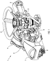
- Figure 1 shows a part section view of an electric valve actuator 1, comprising an electric motor 2 (for example, a brushless DC electric motor or an AC induction motor) for electric powered operation of a valve (not shown); a drivetrain 3 that connects the motor 2 to the valve (for example, via a worm gearing); a terminal compartment 4 for electrical power and data signal connections; an actuator control unit 5 for processing command signals and actuator signals for controlling actuator operations; a position control unit 6 connected to the drivetrain; and a display 7 and local controls 8 for locally viewing and configuring the operation of the actuator 1.
- a hand wheel 8 for manual operation of the valve in emergency situations e.g. when the electric motor 2 is malfunctioning or when no mains power is available) can also be provided.
- Figure 2 illustrates an exploded view of an actuation system 10 that can be used in place of the electric motor 2 and drivetrain 3 described above in relation to Figure 1 .
- the actuation system 10 can be used to provide a compact electric valve actuator capable of providing sufficient torque to operate heavy-duty industrial valves without the need for a large drivetrain / gears.
- Figure 2 is a simplified illustration of the actuation system 10 with components such as electronic devices, PCBs and wires omitted for clarity.
- the actuation system 10 comprises an electric motor, such as a brushless DC motor or a switched reluctance motor, comprising an external stator 11 and an internal rotor 12; a motor housing 20; a hollow output shaft 30; a drive coupling 13 contained within a drive coupling housing 15; and an actuator shaft 14. As shown in Figure 3 , all of these components are arranged on a common central axis which is also the axis of rotation for the internal rotor 12, hollow output shaft 30 and drive coupling 13.
- an electric motor such as a brushless DC motor or a switched reluctance motor
- the internal rotor 12 is hollow, having a central, axially-extending bore. As shown in Figure 3 , the internal rotor 12 is substantially contained within the external stator 11 such that the inner surface of the stator 11 surrounds the outer surface of the internal rotor 12.
- Both the external stator 11 and internal rotor 12 are mounted within a generally circular motor housing 20 by which the system 10 can be located in an actuator housing.
- the motor housing 20 comprises a base 23, a cover 22, and a lid 21, each having a central aperture.
- the drive coupling housing 15 is located on a lower surface of the base 23 (i.e. the external surface of the base 23 / the surface of the base 23 external to the motor enclosing space of the motor housing 20).
- the cover 22 is held in a spaced arrangement with the base 23 by means of locating members 25 between peripheral regions of the cover 22 and base 23 so as to secure the stator 11 and rotor 12 in place within the motor housing 20.
- the cover 22 has open regions 26, and the lid 21 is removably fixed to the upper surface of the cover 22 (i.e. the external surface of the cover 22 / the surface of the cover 22 external to the motor enclosing space of the motor housing 20) so as to close the open regions 26.
- the locating members 25 can comprise threaded rods and nuts, the threaded rods extending through clearance counterbore holes in the cover 22 and base 23 of the motor housing.
- the lid 21 and/or cover 22 of the motor housing 20 can provide means of attaching components (such as electronic components and cables) to the motor housing 20.
- Bearings 27, 28 are provided in the cover 22 and base 23 of the motor housing 20 to allow the internal rotor 12 to be rotatable in the motor housing 20.
- the electric motor 11, 12 can be mounted directly onto the actuator housing, instead of being mounted within the above described motor housing 20, in which case bearings would be provided in the actuator housing to allow the internal rotor 12 to be rotatable in the actuator housing.
- the stator 11 would be fixed to the actuator housing by means such as heat shrinking, bonding or mechanical key fitting(s) to prevent rotation of the stator 11 within the actuator housing.
- the hollow output shaft 30 comprises a hollow cylinder having an external flange 31 protruding radially from the outer surface at its upper end region.
- the hollow output shaft 30 is mounted within the internal rotor 12 by means of fixing means, such as bolts, between the flange 31 and the internal rotor 12 to allow the hollow output shaft 30 to rotate with the internal rotor 12.
- the upper surface of the flange 31 engages the bearing 27 in the upper portion of the housing (e.g. upper portion 22 or an upper portion of the actuator housing).
- the lower end of the rotor 12 engages the bearing 28 in the lower portion of the housing (e.g. base 23 or a lower portion of the actuator housing).
- the lower end of the shaft 30 projects through the central aperture of the lower portion of the housing (e.g. base 23 or a lower portion of the actuator housing).
- the drive coupling housing 15 is fixed to the lower portion of the motor housing 20 (i.e. base 23) or actuator housing around the central aperture.
- the drive coupling 13 is mounted for rotation in bearings 16 in the drive coupling housing 15.
- the hollow output shaft 30 has axially-extending lugs 32a, 32b at one end (i.e. its lower end).
- the lugs 32a, 32b engage in corresponding cut-outs 33a, 33b provided at one end of the drive coupling 13 such that the drive coupling 13 can rotate in the bearings 16 with the hollow output shaft 30.
- axially-extending lugs can be provided at one end of the drive coupling 13 and corresponding cut-outs can be provided at one end of the hollow output shaft 30.
- the drive coupling 13 comprises a drive nut having an internally threaded bore.
- the valve actuator shaft 14 extends through the hollow output shaft 30 and drive coupling 13 and has an external thread that engages the internal thread of the drive coupling 13. This engagement allows rotation of the drive coupling 13 relative to the actuator shaft 14 to be converted into linear movement of the shaft 14. Thus, actuation of the rotor 12 moves the actuator shaft 14 axially. If a valve is provided at one end (i.e. the lower end) of the actuator shaft 14 (e.g. wherein the actuator shaft is directly connected to the valve, or wherein the actuator shaft is a threaded valve stem comprising a valve at its lower end), the axial movement of the actuator shaft 14 in turn operates the valve allowing the electric motor 11, 12 to directly act on the valve.
- the pitch of the threads on the drive coupling and shaft 14 determine the degree of axial movement of the shaft per turn of the rotor 12.
- the drive coupling 13 can be a recirculating ball screw nut or a roller screw nut.
- the actuation system 10 can comprise an anti-back drive coupling.
- a hand wheel (not shown) can be provided for manual operation of the valve in emergency situations (e.g. when the electric motor is malfunctioning or when no mains power is available).
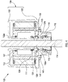
- Figures 4-8 illustrate a second, alternative actuation system 100 that can also be used in place of the system described above in relation to Figures 2-3 .
- Figures 4-8 are a simplified illustration of the second actuation system 100 with components such as electronic devices, PCBs and wires omitted for clarity.
- the second actuation system 100 comprises an electric motor comprising an external stator 111 and an internal rotor 112; a motor housing 120; a hollow output shaft 130; a drive coupling 113 contained within a drive coupling housing 115; and an actuator shaft 114, all of which are generally configured in the same manner as the system shown in Figures. 2-3 .
- the cover 122 extends from the base 123 of the motor housing around the stator 111 and rotor 112, defining an internal tube 122a, so as to secure the stator 111 and rotor 112 in place within the motor housing 120.
- the internal rotor 112 is mounted on bearings 127, 128 on the internal tube 122a to allow the internal rotor 112 to be rotatable within the motor housing 120.
- the internal rotor 112 is also mounted on a seal 124 on the internal tube 122a and a seal 129 in the central aperture of the lower portion of the housing (e.g. base 123 or a lower portion of the actuator housing) to allow components of the electric motor 111, 112 (e.g.
- the cover 122 can have open regions, and the motor housing 120 can further comprise a lid that can be removably fixed to the upper surface of the cover 122 (i.e. the external surface of the cover 122 / the surface of the cover 122 external to the motor enclosing space of the motor housing 120) so as to close the open regions 26. At least one seal can be provided between the lid and the open regions.
- the cover 122 and/or lid of the motor housing 120 can provide means of attaching components (such as electronic components and cables) to the motor housing 120.
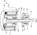
- the hollow output shaft 130 has axially -extending lugs 132a, 132b at one end (i.e. its lower end / the end that extends through the central aperture of the lower portion of the housing (e.g. base 123 or a lower portion of the actuator housing)) that engage in corresponding cut-outs 133a, 133b (see Figure 8 ) provided at one end of the drive coupling
- drive coupling assembly is connected to the base of the motor housing.
- the drive coupling assembly is also external to the motor housing as the electric motor is on one side of the base of the motor housing (i.e. on the internal side of the motor housing) and the drive coupling assembly is on the other side of the base of the motor housing (i.e. on the external side to the motor housing).
- the connection between the drive coupling assembly and the motor housing is releasable as the drive coupling assembly and the motor housing are connected to each other via at least one removable fixing element.
- the removable fixing elements comprise bolts 41, 141 that extend through clearance holes provided on a flange 42, 142 of the drive coupling housing 15, 115 and engage threaded holes in the base 23, 123 of the motor housing.
- the engagement between the lug(s) and the corresponding cut-out(s) formed in respective parts of the drive coupling (i.e. drive coupling 13 or drive coupling 113) and the hollow output shaft (i.e. shaft 30 or shaft 130) allows the motor assembly to be easily moved away from the drive coupling assembly and the actuator shaft (e.g. for maintenance), as shown in Figures 7 and 8 , as the lug(s) and cut-out(s) can be disengaged by simply moving the motor assembly axially away from the drive coupling assembly once the connection between the drive coupling assembly and the motor housing has been released. Moreover, this can be done without affecting the position of the actuator shaft (i.e.
- the actuator shaft 14 or shaft 114) as the actuator shaft is indirectly connected to the motor assembly via the drive coupling assembly (i.e. the engagement between the lug(s) and cut-out(s)). If a valve is provided at one end of the actuator shaft (i.e. the lower end of the actuator shaft), this means the motor assembly can be safely removed for repair or replacement without taking the valve out of service.
- the drive coupling housing (i.e. drive coupling housing 15 or drive coupling housing 115) can be connected to a valve housing, within which the valve components are secured.
- the valve housing can define the drive coupling housing (i.e. drive coupling housing 15 or drive coupling housing 115).
- drive electronics and IGBT (Insulated-Gate Bipolar Transistor) modules can be used to switch the current to the motor windings using pulse-width modulation (PWM) control.
- the IGBT modules can be arranged radially around the motor end windings and electrically connected to the motor end winding terminations.
- Epoxylite ® (or a similar material known in the art) can be used to substantially or completely encapsulate components of the electric motor to be used with the compact actuation system 10 and 100 (e.g. the stator windings of the electric motor, motor drive electronics and IGBT modules at the end of the motor end windings).
- this can be achieved by using the motor housing 120 as a mould and pouring molten Epoxylite ® (or a similar material) into an opening of the motor housing 120 (e.g. an opening provided between the internal rotor 112 and the base of the motor housing 123) and allowing the Epoxylite ® (or a similar material) to solidify.
- Encapsulating the components of the electric motor in Epoxylite ® can allow the compact actuation system (i.e. compact actuation system 10 or 100) to be explosion proof, as the Epoxylite ® (or a similar material) acts as a barrier between potentially explosive atmospheres and the encapsulated components that can be sources of spark ignition (such as the motor windings and drive electronics).
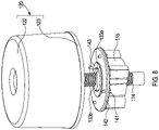
- FIG. 9 illustrates an embodiment of this arrangement, which includes a gearbox 350 housing a planetary gear arrangement including a sun gear 352 and a series of planet gears 354.
- the sun gear 352 is hollow and is mounted concentrically with the hollow output shaft 330 and drive coupling 313 in the drive coupling housing 315 (and hence with the actuator shaft, not shown).
- the sun gear 352 is mounted on a sun gear carrier 356 which is mounted in bearing in the upper part of the gearbox 350 and has cut-outs 333 to receive lugs 332 on the end of the hollow output shaft 330.
- the planet gears 354 are mounted on a planet gear carrier 358 which rotates with the planet gears 354 and transmits the rotation to the drive coupling 313 through drive lugs 360.
- the motor and gearbox can be separate units so that the motor can be removed from the gearbox. Similarly, the gearbox can be removed from the drive coupling and so leave the valve in position, as is discussed above.
- Figure 9 shows a single stage planetary gear system
- the planet gear carrier can be connected to a hollow sun gear of a subsequent planetary gear stage. Two or more subsequent stages can be used.
- the gearbox could be spur gear type or bevel gear type with a hollow output shaft to allow the actuator shaft to rise up through the gearbox output gear.
- the actuator shaft may not rise up through the hollow output shaft of the motor as the motor rotation axis may no longer be concentric with the gearbox output axis.
- the direct acting motor arrangement described above, or the direct acting motor coupled to a gearbox could be used in conjunction with an anti-back drive coupling to operate a 1 ⁇ 4 turn valve such as a ball valve or butterfly valve.
- This type of 1 ⁇ 4 turn valve does not have a rising valve stem or actuator shaft.
- the anti-back drive coupling could potentially be left attached to the valve to maintain the position of the valve whilst the motor was removed for maintenance or replacement in a similar way to what is described above.
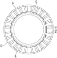
- FIG 10 shows a cross section view of an electric motor 211, 212 that can be used with the compact actuation systems 10 and 100 described above.
- the stator 211 consists of an external stator body 213 with a series of inwardly projecting stator teeth 214.
- the sides of the stator teeth 214 are substantially straight along the whole length of each tooth. It has previously been proposed to provide lateral extensions or tips at the end of each tooth (i.e. the sides extend laterally towards the adjacent tooth at the end). This has been done to reduce high levels of flux density in the stator leading to excess heat being generated in use. In effect, the external stator 211 has no stator tooth tips.
- the motor can have low rotational output speeds such that iron losses and heat generation are less of an issue.
- the motor is to be operated, for example, with a 25% duty cycles rather than being rated to run continuously and the external stator 211 can be relatively large in size, relative to the motor output power, and thus has a large thermal mass that helps distribute any heat generated.
- Lack of stator tooth tips on the external stator 211 can substantially simplify the coil assembly process as pre-wound concentrated 'coil packs' can be assembled onto the stator 211 by simply sliding them onto the stator teeth, as opposed to having to wind coils onto the stator 211 in situ.
- the process of carrying out maintenance on such a stator 211 is also simplified as said 'coil packs' can be easily removed from the stator teeth by simply sliding them away from the stator teeth.
- a motor having these features, such as a brushless DC motor or a switched reluctance motor, can find use in applications in addition to the valve actuator disclosed above. This invention extends to such uses.
Landscapes
- Engineering & Computer Science (AREA)
- General Engineering & Computer Science (AREA)
- Power Engineering (AREA)
- Mechanical Engineering (AREA)
- Connection Of Motors, Electrical Generators, Mechanical Devices, And The Like (AREA)
- Valve Device For Special Equipments (AREA)
- Fluid-Driven Valves (AREA)
- Actuator (AREA)
- Motor Or Generator Frames (AREA)
Applications Claiming Priority (3)
| Application Number | Priority Date | Filing Date | Title |
|---|---|---|---|
| GBGB1821097.1A GB201821097D0 (en) | 2018-12-21 | 2018-12-21 | Actuator |
| GB1910743.2A GB2580198B (en) | 2018-12-21 | 2019-07-26 | Actuator |
| PCT/GB2019/053563 WO2020128443A1 (en) | 2018-12-21 | 2019-12-16 | Actuator |
Publications (2)
| Publication Number | Publication Date |
|---|---|
| EP3899321A1 EP3899321A1 (en) | 2021-10-27 |
| EP3899321B1 true EP3899321B1 (en) | 2022-11-16 |
Family
ID=65364485
Family Applications (1)
| Application Number | Title | Priority Date | Filing Date |
|---|---|---|---|
| EP19823975.8A Active EP3899321B1 (en) | 2018-12-21 | 2019-12-16 | Actuator |
Country Status (11)
| Country | Link |
|---|---|
| US (2) | US11692638B2 (pl) |
| EP (1) | EP3899321B1 (pl) |
| KR (2) | KR102804676B1 (pl) |
| CN (2) | CN113366245B (pl) |
| CL (1) | CL2021001647A1 (pl) |
| ES (1) | ES2938487T3 (pl) |
| GB (2) | GB201821097D0 (pl) |
| MY (1) | MY208182A (pl) |
| PL (1) | PL3899321T3 (pl) |
| SA (1) | SA521422314B1 (pl) |
| WO (1) | WO2020128443A1 (pl) |
Families Citing this family (4)
| Publication number | Priority date | Publication date | Assignee | Title |
|---|---|---|---|---|
| GB201821097D0 (en) * | 2018-12-21 | 2019-02-06 | Rotork Controls | Actuator |
| US20250164027A1 (en) * | 2022-04-21 | 2025-05-22 | Fujikoki Corporation | Electric valve |
| CN114962763B (zh) * | 2022-07-28 | 2022-12-09 | 常州兰控阀门控制有限公司 | 一种手动电动一体的智能电动执行器 |
| US20240263689A1 (en) * | 2023-02-08 | 2024-08-08 | Archibald Corporation | Electric motor having stationary drive mechanism |
Family Cites Families (22)
| Publication number | Priority date | Publication date | Assignee | Title |
|---|---|---|---|---|
| GB862324A (en) * | 1958-01-20 | 1961-03-08 | Atomic Energy Authority Uk | Improvements in or relating to nuclear reactors |
| US2992807A (en) * | 1959-04-15 | 1961-07-18 | Rockwell Mfg Co | Motor driven impact valve operator |
| US3327826A (en) * | 1965-08-03 | 1967-06-27 | Superior Electric Co | Braked linear actuator operated by rotational movement |
| GB8824041D0 (en) * | 1988-10-13 | 1988-11-23 | Sneddon J L | Linear actuators & linear drive systems |
| US5295907A (en) * | 1990-05-04 | 1994-03-22 | Ava International Corporation | Rorque limiting device |
| FR2693533B1 (fr) * | 1992-07-09 | 1994-10-14 | Europ Propulsion | Vanne à commande électrique et à boisseau distributeur totalement étanche. |
| DE4332323C2 (de) * | 1993-09-23 | 1995-11-30 | Leybold Ag | Getriebemotor mit einem eine Hohlwelle aufweisenden Elektromotor |
| US5848610A (en) * | 1996-11-14 | 1998-12-15 | Livernash; Robert A. | Motorized diverter valve |
| JP2002145080A (ja) * | 2000-11-10 | 2002-05-22 | Nsk Ltd | 電動パワーステアリング装置 |
| GB0424249D0 (en) * | 2004-11-02 | 2004-12-01 | Camcon Ltd | Improved actuator requiring low power for actuation for remotely located valve operation and valve actuator combination |
| US20070068583A1 (en) * | 2005-09-27 | 2007-03-29 | Johnson Dwight N | Motor-driven hydraulic valve cartridge |
| JP4475222B2 (ja) * | 2005-11-07 | 2010-06-09 | トヨタ自動車株式会社 | バルブタイミング制御装置 |
| KR100777333B1 (ko) * | 2007-04-11 | 2007-11-20 | 주식회사 흥진에이티 | 감속기 |
| PT2440822E (pt) * | 2009-06-09 | 2013-07-11 | Mokveld Valves Bv | Válvula |
| WO2011161394A1 (en) * | 2010-06-22 | 2011-12-29 | Rotork Controls Limited | Improvements in and relating to anti back-drive couplings |
| US9590471B2 (en) * | 2012-11-16 | 2017-03-07 | Nti Ag | Rotary lifting device |
| US9605736B1 (en) * | 2013-05-31 | 2017-03-28 | Rct Systems, Inc. | High temperature electromagnetic actuator |
| KR101520922B1 (ko) * | 2013-11-13 | 2015-05-18 | 유도스타자동화 주식회사 | 사출성형기의 밸브 모터장치 |
| US9797490B2 (en) * | 2014-03-27 | 2017-10-24 | Lcdrives Corp. | High reliability actuator |
| JP6481155B2 (ja) * | 2014-11-25 | 2019-03-13 | 株式会社テージーケー | 電動弁 |
| NO341070B1 (no) * | 2016-02-10 | 2017-08-21 | Electrical Subsea & Drilling As | Elektromekanisk kraftaktuator |
| GB201821097D0 (en) * | 2018-12-21 | 2019-02-06 | Rotork Controls | Actuator |
-
2018
- 2018-12-21 GB GBGB1821097.1A patent/GB201821097D0/en not_active Ceased
-
2019
- 2019-07-26 GB GB1910743.2A patent/GB2580198B/en active Active
- 2019-12-16 CN CN201980085021.9A patent/CN113366245B/zh active Active
- 2019-12-16 US US17/415,927 patent/US11692638B2/en active Active
- 2019-12-16 ES ES19823975T patent/ES2938487T3/es active Active
- 2019-12-16 MY MYPI2021003299A patent/MY208182A/en unknown
- 2019-12-16 CN CN202510235220.0A patent/CN120074106A/zh active Pending
- 2019-12-16 KR KR1020217023223A patent/KR102804676B1/ko active Active
- 2019-12-16 WO PCT/GB2019/053563 patent/WO2020128443A1/en not_active Ceased
- 2019-12-16 KR KR1020257014464A patent/KR20250065437A/ko active Pending
- 2019-12-16 PL PL19823975.8T patent/PL3899321T3/pl unknown
- 2019-12-16 EP EP19823975.8A patent/EP3899321B1/en active Active
-
2021
- 2021-06-17 SA SA521422314A patent/SA521422314B1/ar unknown
- 2021-06-18 CL CL2021001647A patent/CL2021001647A1/es unknown
-
2023
- 2023-05-12 US US18/196,510 patent/US12359741B2/en active Active
Also Published As
| Publication number | Publication date |
|---|---|
| GB2580198A (en) | 2020-07-15 |
| BR112021012052A2 (pt) | 2021-10-19 |
| US20230279964A1 (en) | 2023-09-07 |
| GB201821097D0 (en) | 2019-02-06 |
| GB2580198B (en) | 2021-01-13 |
| KR20210114424A (ko) | 2021-09-23 |
| SA521422314B1 (ar) | 2023-02-21 |
| PL3899321T3 (pl) | 2023-05-08 |
| WO2020128443A1 (en) | 2020-06-25 |
| KR102804676B1 (ko) | 2025-05-07 |
| MY208182A (en) | 2025-04-22 |
| ES2938487T3 (es) | 2023-04-11 |
| EP3899321A1 (en) | 2021-10-27 |
| US20220065361A1 (en) | 2022-03-03 |
| CN113366245B (zh) | 2025-03-18 |
| CL2021001647A1 (es) | 2022-02-11 |
| GB201910743D0 (en) | 2019-09-11 |
| CN120074106A (zh) | 2025-05-30 |
| US11692638B2 (en) | 2023-07-04 |
| CN113366245A (zh) | 2021-09-07 |
| US12359741B2 (en) | 2025-07-15 |
| KR20250065437A (ko) | 2025-05-12 |
Similar Documents
| Publication | Publication Date | Title |
|---|---|---|
| US12359741B2 (en) | Actuator | |
| US12255518B2 (en) | Driving motor having BLDC motor and swivel actuator using same | |
| US5595089A (en) | Actuator for steering rear wheels | |
| CN101945797B (zh) | 车辆用操舵装置 | |
| JP4817671B2 (ja) | 減速装置付電動弁 | |
| US8235165B2 (en) | Electromechanical power steering system with a ball screw drive | |
| EP0974184B1 (en) | Compact drive | |
| US20230369939A1 (en) | Drive motor provided with bldc motor and swivel actuator using same | |
| EP2811625A1 (en) | Gearmotor with reduced axial space requirement | |
| US11177718B2 (en) | Electric actuator with screw shaft | |
| CN116117857B (zh) | 机器人关节模组 | |
| JP7192635B2 (ja) | 回転式アクチュエータ | |
| RU2801261C2 (ru) | Привод | |
| BR112021012052B1 (pt) | Atuador e sistema de acionamento | |
| CN211791106U (zh) | 一种紧凑型电动执行装置 | |
| WO2024105487A1 (en) | Variable air-gap electric motor | |
| GB2457336A (en) | CVT with motor/generators having stators moved by worm wheel and worm screw | |
| JP2008172975A (ja) | インホイールモータ駆動装置 | |
| CN216929785U (zh) | 一种特殊环境下电机快换装置 | |
| US3204479A (en) | Valve operator with dual gearing | |
| WO2025164797A1 (ja) | 磁気歯車装置 | |
| CN120886233A (zh) | 一种机器人的力控机械臂 | |
| JPS61139560A (ja) | 電気式動力舵取装置 | |
| KR20250130895A (ko) | 리어 휠 스티어링 장치 |
Legal Events
| Date | Code | Title | Description |
|---|---|---|---|
| STAA | Information on the status of an ep patent application or granted ep patent |
Free format text: STATUS: UNKNOWN |
|
| STAA | Information on the status of an ep patent application or granted ep patent |
Free format text: STATUS: THE INTERNATIONAL PUBLICATION HAS BEEN MADE |
|
| PUAI | Public reference made under article 153(3) epc to a published international application that has entered the european phase |
Free format text: ORIGINAL CODE: 0009012 |
|
| STAA | Information on the status of an ep patent application or granted ep patent |
Free format text: STATUS: REQUEST FOR EXAMINATION WAS MADE |
|
| 17P | Request for examination filed |
Effective date: 20210701 |
|
| AK | Designated contracting states |
Kind code of ref document: A1 Designated state(s): AL AT BE BG CH CY CZ DE DK EE ES FI FR GB GR HR HU IE IS IT LI LT LU LV MC MK MT NL NO PL PT RO RS SE SI SK SM TR |
|
| DAV | Request for validation of the european patent (deleted) | ||
| DAX | Request for extension of the european patent (deleted) | ||
| GRAP | Despatch of communication of intention to grant a patent |
Free format text: ORIGINAL CODE: EPIDOSNIGR1 |
|
| STAA | Information on the status of an ep patent application or granted ep patent |
Free format text: STATUS: GRANT OF PATENT IS INTENDED |
|
| INTG | Intention to grant announced |
Effective date: 20220706 |
|
| RIN1 | Information on inventor provided before grant (corrected) |
Inventor name: ADAMS, DAVID |
|
| GRAS | Grant fee paid |
Free format text: ORIGINAL CODE: EPIDOSNIGR3 |
|
| GRAA | (expected) grant |
Free format text: ORIGINAL CODE: 0009210 |
|
| STAA | Information on the status of an ep patent application or granted ep patent |
Free format text: STATUS: THE PATENT HAS BEEN GRANTED |
|
| AK | Designated contracting states |
Kind code of ref document: B1 Designated state(s): AL AT BE BG CH CY CZ DE DK EE ES FI FR GB GR HR HU IE IS IT LI LT LU LV MC MK MT NL NO PL PT RO RS SE SI SK SM TR |
|
| REG | Reference to a national code |
Ref country code: GB Ref legal event code: FG4D |
|
| REG | Reference to a national code |
Ref country code: CH Ref legal event code: EP |
|
| REG | Reference to a national code |
Ref country code: DE Ref legal event code: R096 Ref document number: 602019022064 Country of ref document: DE |
|
| REG | Reference to a national code |
Ref country code: IE Ref legal event code: FG4D |
|
| REG | Reference to a national code |
Ref country code: AT Ref legal event code: REF Ref document number: 1531943 Country of ref document: AT Kind code of ref document: T Effective date: 20221215 |
|
| REG | Reference to a national code |
Ref country code: NL Ref legal event code: FP |
|
| REG | Reference to a national code |
Ref country code: SE Ref legal event code: TRGR |
|
| REG | Reference to a national code |
Ref country code: LT Ref legal event code: MG9D |
|
| REG | Reference to a national code |
Ref country code: ES Ref legal event code: FG2A Ref document number: 2938487 Country of ref document: ES Kind code of ref document: T3 Effective date: 20230411 |
|
| REG | Reference to a national code |
Ref country code: AT Ref legal event code: MK05 Ref document number: 1531943 Country of ref document: AT Kind code of ref document: T Effective date: 20221116 |
|
| PG25 | Lapsed in a contracting state [announced via postgrant information from national office to epo] |
Ref country code: PT Free format text: LAPSE BECAUSE OF FAILURE TO SUBMIT A TRANSLATION OF THE DESCRIPTION OR TO PAY THE FEE WITHIN THE PRESCRIBED TIME-LIMIT Effective date: 20230316 Ref country code: NO Free format text: LAPSE BECAUSE OF FAILURE TO SUBMIT A TRANSLATION OF THE DESCRIPTION OR TO PAY THE FEE WITHIN THE PRESCRIBED TIME-LIMIT Effective date: 20230216 Ref country code: LT Free format text: LAPSE BECAUSE OF FAILURE TO SUBMIT A TRANSLATION OF THE DESCRIPTION OR TO PAY THE FEE WITHIN THE PRESCRIBED TIME-LIMIT Effective date: 20221116 Ref country code: FI Free format text: LAPSE BECAUSE OF FAILURE TO SUBMIT A TRANSLATION OF THE DESCRIPTION OR TO PAY THE FEE WITHIN THE PRESCRIBED TIME-LIMIT Effective date: 20221116 Ref country code: AT Free format text: LAPSE BECAUSE OF FAILURE TO SUBMIT A TRANSLATION OF THE DESCRIPTION OR TO PAY THE FEE WITHIN THE PRESCRIBED TIME-LIMIT Effective date: 20221116 |
|
| PG25 | Lapsed in a contracting state [announced via postgrant information from national office to epo] |
Ref country code: RS Free format text: LAPSE BECAUSE OF FAILURE TO SUBMIT A TRANSLATION OF THE DESCRIPTION OR TO PAY THE FEE WITHIN THE PRESCRIBED TIME-LIMIT Effective date: 20221116 Ref country code: LV Free format text: LAPSE BECAUSE OF FAILURE TO SUBMIT A TRANSLATION OF THE DESCRIPTION OR TO PAY THE FEE WITHIN THE PRESCRIBED TIME-LIMIT Effective date: 20221116 Ref country code: IS Free format text: LAPSE BECAUSE OF FAILURE TO SUBMIT A TRANSLATION OF THE DESCRIPTION OR TO PAY THE FEE WITHIN THE PRESCRIBED TIME-LIMIT Effective date: 20230316 Ref country code: HR Free format text: LAPSE BECAUSE OF FAILURE TO SUBMIT A TRANSLATION OF THE DESCRIPTION OR TO PAY THE FEE WITHIN THE PRESCRIBED TIME-LIMIT Effective date: 20221116 Ref country code: GR Free format text: LAPSE BECAUSE OF FAILURE TO SUBMIT A TRANSLATION OF THE DESCRIPTION OR TO PAY THE FEE WITHIN THE PRESCRIBED TIME-LIMIT Effective date: 20230217 |
|
| PG25 | Lapsed in a contracting state [announced via postgrant information from national office to epo] |
Ref country code: SM Free format text: LAPSE BECAUSE OF FAILURE TO SUBMIT A TRANSLATION OF THE DESCRIPTION OR TO PAY THE FEE WITHIN THE PRESCRIBED TIME-LIMIT Effective date: 20221116 Ref country code: RO Free format text: LAPSE BECAUSE OF FAILURE TO SUBMIT A TRANSLATION OF THE DESCRIPTION OR TO PAY THE FEE WITHIN THE PRESCRIBED TIME-LIMIT Effective date: 20221116 Ref country code: IT Free format text: LAPSE BECAUSE OF NON-PAYMENT OF DUE FEES Effective date: 20221216 Ref country code: EE Free format text: LAPSE BECAUSE OF FAILURE TO SUBMIT A TRANSLATION OF THE DESCRIPTION OR TO PAY THE FEE WITHIN THE PRESCRIBED TIME-LIMIT Effective date: 20221116 Ref country code: DK Free format text: LAPSE BECAUSE OF FAILURE TO SUBMIT A TRANSLATION OF THE DESCRIPTION OR TO PAY THE FEE WITHIN THE PRESCRIBED TIME-LIMIT Effective date: 20221116 |
|
| REG | Reference to a national code |
Ref country code: DE Ref legal event code: R097 Ref document number: 602019022064 Country of ref document: DE |
|
| PG25 | Lapsed in a contracting state [announced via postgrant information from national office to epo] |
Ref country code: SK Free format text: LAPSE BECAUSE OF FAILURE TO SUBMIT A TRANSLATION OF THE DESCRIPTION OR TO PAY THE FEE WITHIN THE PRESCRIBED TIME-LIMIT Effective date: 20221116 Ref country code: LU Free format text: LAPSE BECAUSE OF NON-PAYMENT OF DUE FEES Effective date: 20221216 Ref country code: AL Free format text: LAPSE BECAUSE OF FAILURE TO SUBMIT A TRANSLATION OF THE DESCRIPTION OR TO PAY THE FEE WITHIN THE PRESCRIBED TIME-LIMIT Effective date: 20221116 |
|
| P01 | Opt-out of the competence of the unified patent court (upc) registered |
Effective date: 20230816 |
|
| PLBE | No opposition filed within time limit |
Free format text: ORIGINAL CODE: 0009261 |
|
| STAA | Information on the status of an ep patent application or granted ep patent |
Free format text: STATUS: NO OPPOSITION FILED WITHIN TIME LIMIT |
|
| 26N | No opposition filed |
Effective date: 20230817 |
|
| PG25 | Lapsed in a contracting state [announced via postgrant information from national office to epo] |
Ref country code: IT Free format text: LAPSE BECAUSE OF NON-PAYMENT OF DUE FEES Effective date: 20221216 |
|
| PGRI | Patent reinstated in contracting state [announced from national office to epo] |
Ref country code: IT Effective date: 20221231 |
|
| REG | Reference to a national code |
Ref country code: DE Ref legal event code: R082 Ref document number: 602019022064 Country of ref document: DE Representative=s name: KANDLBINDER, MARKUS, DIPL.-PHYS., DE |
|
| PG25 | Lapsed in a contracting state [announced via postgrant information from national office to epo] |
Ref country code: SI Free format text: LAPSE BECAUSE OF FAILURE TO SUBMIT A TRANSLATION OF THE DESCRIPTION OR TO PAY THE FEE WITHIN THE PRESCRIBED TIME-LIMIT Effective date: 20221116 |
|
| PG25 | Lapsed in a contracting state [announced via postgrant information from national office to epo] |
Ref country code: CY Free format text: LAPSE BECAUSE OF FAILURE TO SUBMIT A TRANSLATION OF THE DESCRIPTION OR TO PAY THE FEE WITHIN THE PRESCRIBED TIME-LIMIT Effective date: 20221116 |
|
| PG25 | Lapsed in a contracting state [announced via postgrant information from national office to epo] |
Ref country code: MK Free format text: LAPSE BECAUSE OF FAILURE TO SUBMIT A TRANSLATION OF THE DESCRIPTION OR TO PAY THE FEE WITHIN THE PRESCRIBED TIME-LIMIT Effective date: 20221116 Ref country code: HU Free format text: LAPSE BECAUSE OF FAILURE TO SUBMIT A TRANSLATION OF THE DESCRIPTION OR TO PAY THE FEE WITHIN THE PRESCRIBED TIME-LIMIT; INVALID AB INITIO Effective date: 20191216 |
|
| PG25 | Lapsed in a contracting state [announced via postgrant information from national office to epo] |
Ref country code: MC Free format text: LAPSE BECAUSE OF FAILURE TO SUBMIT A TRANSLATION OF THE DESCRIPTION OR TO PAY THE FEE WITHIN THE PRESCRIBED TIME-LIMIT Effective date: 20221116 |
|
| PG25 | Lapsed in a contracting state [announced via postgrant information from national office to epo] |
Ref country code: MC Free format text: LAPSE BECAUSE OF FAILURE TO SUBMIT A TRANSLATION OF THE DESCRIPTION OR TO PAY THE FEE WITHIN THE PRESCRIBED TIME-LIMIT Effective date: 20221116 |
|
| PG25 | Lapsed in a contracting state [announced via postgrant information from national office to epo] |
Ref country code: BG Free format text: LAPSE BECAUSE OF FAILURE TO SUBMIT A TRANSLATION OF THE DESCRIPTION OR TO PAY THE FEE WITHIN THE PRESCRIBED TIME-LIMIT Effective date: 20221116 |
|
| PG25 | Lapsed in a contracting state [announced via postgrant information from national office to epo] |
Ref country code: MT Free format text: LAPSE BECAUSE OF FAILURE TO SUBMIT A TRANSLATION OF THE DESCRIPTION OR TO PAY THE FEE WITHIN THE PRESCRIBED TIME-LIMIT Effective date: 20221116 |
|
| PGFP | Annual fee paid to national office [announced via postgrant information from national office to epo] |
Ref country code: NL Payment date: 20241111 Year of fee payment: 6 |
|
| PGFP | Annual fee paid to national office [announced via postgrant information from national office to epo] |
Ref country code: DE Payment date: 20241216 Year of fee payment: 6 |
|
| PGFP | Annual fee paid to national office [announced via postgrant information from national office to epo] |
Ref country code: BE Payment date: 20241111 Year of fee payment: 6 Ref country code: PL Payment date: 20241114 Year of fee payment: 6 |
|
| PGFP | Annual fee paid to national office [announced via postgrant information from national office to epo] |
Ref country code: GB Payment date: 20241112 Year of fee payment: 6 |
|
| PGFP | Annual fee paid to national office [announced via postgrant information from national office to epo] |
Ref country code: FR Payment date: 20241219 Year of fee payment: 6 |
|
| PGFP | Annual fee paid to national office [announced via postgrant information from national office to epo] |
Ref country code: CZ Payment date: 20241203 Year of fee payment: 6 Ref country code: IE Payment date: 20241113 Year of fee payment: 6 |
|
| PGFP | Annual fee paid to national office [announced via postgrant information from national office to epo] |
Ref country code: IT Payment date: 20241216 Year of fee payment: 6 |
|
| PGFP | Annual fee paid to national office [announced via postgrant information from national office to epo] |
Ref country code: SE Payment date: 20241113 Year of fee payment: 6 |
|
| PGFP | Annual fee paid to national office [announced via postgrant information from national office to epo] |
Ref country code: TR Payment date: 20241018 Year of fee payment: 6 |
|
| PGFP | Annual fee paid to national office [announced via postgrant information from national office to epo] |
Ref country code: ES Payment date: 20250117 Year of fee payment: 6 |
|
| PGFP | Annual fee paid to national office [announced via postgrant information from national office to epo] |
Ref country code: CH Payment date: 20250101 Year of fee payment: 6 |