EP3897406B1 - Hämostase-clip mit zusammenklappbarer kapsel - Google Patents
Hämostase-clip mit zusammenklappbarer kapsel Download PDFInfo
- Publication number
- EP3897406B1 EP3897406B1 EP20727456.4A EP20727456A EP3897406B1 EP 3897406 B1 EP3897406 B1 EP 3897406B1 EP 20727456 A EP20727456 A EP 20727456A EP 3897406 B1 EP3897406 B1 EP 3897406B1
- Authority
- EP
- European Patent Office
- Prior art keywords
- cap
- capsule
- longitudinal body
- proximal
- clip arms
- Prior art date
- Legal status (The legal status is an assumption and is not a legal conclusion. Google has not performed a legal analysis and makes no representation as to the accuracy of the status listed.)
- Active
Links
Images


Classifications
-
- A—HUMAN NECESSITIES
- A61—MEDICAL OR VETERINARY SCIENCE; HYGIENE
- A61B—DIAGNOSIS; SURGERY; IDENTIFICATION
- A61B17/00—Surgical instruments, devices or methods
- A61B17/12—Surgical instruments, devices or methods for ligaturing or otherwise compressing tubular parts of the body, e.g. blood vessels or umbilical cord
- A61B17/122—Clamps or clips, e.g. for the umbilical cord
- A61B17/1227—Spring clips
-
- A—HUMAN NECESSITIES
- A61—MEDICAL OR VETERINARY SCIENCE; HYGIENE
- A61B—DIAGNOSIS; SURGERY; IDENTIFICATION
- A61B17/00—Surgical instruments, devices or methods
- A61B17/00234—Surgical instruments, devices or methods for minimally invasive surgery
-
- A—HUMAN NECESSITIES
- A61—MEDICAL OR VETERINARY SCIENCE; HYGIENE
- A61B—DIAGNOSIS; SURGERY; IDENTIFICATION
- A61B17/00—Surgical instruments, devices or methods
- A61B17/0057—Implements for plugging an opening in the wall of a hollow or tubular organ, e.g. for sealing a vessel puncture or closing a cardiac septal defect
-
- A—HUMAN NECESSITIES
- A61—MEDICAL OR VETERINARY SCIENCE; HYGIENE
- A61B—DIAGNOSIS; SURGERY; IDENTIFICATION
- A61B17/00—Surgical instruments, devices or methods
- A61B17/12—Surgical instruments, devices or methods for ligaturing or otherwise compressing tubular parts of the body, e.g. blood vessels or umbilical cord
- A61B17/128—Surgical instruments, devices or methods for ligaturing or otherwise compressing tubular parts of the body, e.g. blood vessels or umbilical cord for applying or removing clamps or clips
- A61B17/1285—Surgical instruments, devices or methods for ligaturing or otherwise compressing tubular parts of the body, e.g. blood vessels or umbilical cord for applying or removing clamps or clips for minimally invasive surgery
-
- A—HUMAN NECESSITIES
- A61—MEDICAL OR VETERINARY SCIENCE; HYGIENE
- A61B—DIAGNOSIS; SURGERY; IDENTIFICATION
- A61B17/00—Surgical instruments, devices or methods
- A61B17/00234—Surgical instruments, devices or methods for minimally invasive surgery
- A61B2017/00292—Surgical instruments, devices or methods for minimally invasive surgery mounted on or guided by flexible, e.g. catheter-like, means
- A61B2017/0034—Surgical instruments, devices or methods for minimally invasive surgery mounted on or guided by flexible, e.g. catheter-like, means adapted to be inserted through a working channel of an endoscope
-
- A—HUMAN NECESSITIES
- A61—MEDICAL OR VETERINARY SCIENCE; HYGIENE
- A61B—DIAGNOSIS; SURGERY; IDENTIFICATION
- A61B17/00—Surgical instruments, devices or methods
- A61B17/0057—Implements for plugging an opening in the wall of a hollow or tubular organ, e.g. for sealing a vessel puncture or closing a cardiac septal defect
- A61B2017/00575—Implements for plugging an opening in the wall of a hollow or tubular organ, e.g. for sealing a vessel puncture or closing a cardiac septal defect for closure at remote site, e.g. closing atrial septum defects
- A61B2017/00584—Clips
-
- A—HUMAN NECESSITIES
- A61—MEDICAL OR VETERINARY SCIENCE; HYGIENE
- A61B—DIAGNOSIS; SURGERY; IDENTIFICATION
- A61B17/00—Surgical instruments, devices or methods
- A61B17/0057—Implements for plugging an opening in the wall of a hollow or tubular organ, e.g. for sealing a vessel puncture or closing a cardiac septal defect
- A61B2017/00575—Implements for plugging an opening in the wall of a hollow or tubular organ, e.g. for sealing a vessel puncture or closing a cardiac septal defect for closure at remote site, e.g. closing atrial septum defects
- A61B2017/00623—Introducing or retrieving devices therefor
-
- A—HUMAN NECESSITIES
- A61—MEDICAL OR VETERINARY SCIENCE; HYGIENE
- A61B—DIAGNOSIS; SURGERY; IDENTIFICATION
- A61B17/00—Surgical instruments, devices or methods
- A61B2017/00743—Type of operation; Specification of treatment sites
- A61B2017/00818—Treatment of the gastro-intestinal system
-
- A—HUMAN NECESSITIES
- A61—MEDICAL OR VETERINARY SCIENCE; HYGIENE
- A61B—DIAGNOSIS; SURGERY; IDENTIFICATION
- A61B17/00—Surgical instruments, devices or methods
- A61B2017/00831—Material properties
- A61B2017/00862—Material properties elastic or resilient
-
- A—HUMAN NECESSITIES
- A61—MEDICAL OR VETERINARY SCIENCE; HYGIENE
- A61B—DIAGNOSIS; SURGERY; IDENTIFICATION
- A61B17/00—Surgical instruments, devices or methods
- A61B17/12—Surgical instruments, devices or methods for ligaturing or otherwise compressing tubular parts of the body, e.g. blood vessels or umbilical cord
- A61B2017/12004—Surgical instruments, devices or methods for ligaturing or otherwise compressing tubular parts of the body, e.g. blood vessels or umbilical cord for haemostasis, for prevention of bleeding
-
- A—HUMAN NECESSITIES
- A61—MEDICAL OR VETERINARY SCIENCE; HYGIENE
- A61B—DIAGNOSIS; SURGERY; IDENTIFICATION
- A61B90/00—Instruments, implements or accessories specially adapted for surgery or diagnosis and not covered by any of the groups A61B1/00 - A61B50/00, e.g. for luxation treatment or for protecting wound edges
- A61B90/03—Automatic limiting or abutting means, e.g. for safety
- A61B2090/037—Automatic limiting or abutting means, e.g. for safety with a frangible part, e.g. by reduced diameter
Definitions
- the present disclosure relates to endoscopic devices and, in particular, relates to endoscopic clipping devices for treating tissue along the gastrointestinal tract.
- Hemostasis clips may be used for hemostasis of, for example, mucosal/sub-mucosal defects, bleeding ulcers, arteries, polyps, diverticula, along with closure of luminal tract perforations. Depending on the size of the defect, multiple clips may be required.
- US 2019/053804 A1 describes an apparatus for deployment of a hemostatic clip including a clip assembly releasably coupled to a distal portion of a shaft, wherein the clip assembly includes a capsule releasably coupled to the shaft, clip arms slidably received within the capsule and cooperating with the capsule to provide feedback indicating a configuration of the clip assembly, and a yoke slidably received within the capsule, the yoke including proximal and distal portions releasably and rotatably connected to one another via a first control wire, a distal end of the distal portion being connected to proximal ends of the clip arms.
- US 2018/085122 A1 discloses a system for treating tissue which includes a clip assembly including a pair of clip arms, proximal ends of the clip arms slidably received within a channel of a capsule to be moved between a tissue receiving configuration and a tissue clipping configuration, an applicator including a catheter and a control member extending therethrough, a distal end of the control member configured to be connected to the clip arms to move the clip assembly between the tissue receiving and tissue clipping configurations, and a coupler releasably coupled to proximal ends of the clip arms and configured to be coupled to the distal end of the control member, the coupler configured to yield when a proximal force exerted on the coupler via the control member exceeds a first predetermined threshold value to disengage the clip arms to deploy the clip assembly.
- US 2018/078262 A1 discloses a system for treating tissue that includes an applicator including a catheter and a control member extending therethrough, the control member longitudinally movable relative to the catheter and including an abutment structure proximate a distal end thereof, and a clip assembly releasably coupleable to a distal end of the applicator.
- the clip assembly includes a pair of clip arms slidably received within a channel of a capsule and releasably coupled to the control member so that the clip arms are movable relative to the capsule between a tissue receiving configuration and a tissue clipping configuration.
- the capsule includes proximal tabs movable between a biased non-engaging and an engaging configuration, in which the proximal tabs engage an engaging portion of the lumen of the catheter when the abutment structure is received within the capsule.
- US 3 958 576 A1 describes a clip member detachably attached to an instrument body.
- the instrument body has an outer flexible tube, an actuating tubular member inserted into the outer tube, and a wire inserted into the actuating tubular member.
- a holder is detachably mounted through a guide member to the forward end portion of the actuating member.
- To the forward end of the wire is secured a hook member for anchoring the clip member.
- a pair of clamping portions of the clip member is opened by forcefully engaging a pair of offset portions of the clip member with the inner surface of the holder and closed by forcefully engaging a pair of intersecting portions with the inner surface of the holder.
- the presently claimed invention relates to a clipping device according to claim 1. Further developments of the invention can be gathered from the dependent claims.
- the present disclosure is directed to an endoscopic clipping device for treating tissue perforations, defects and/or bleeds.
- a shorter deployed clip may be preferred to improve visualization of the target site and to allow better maneuverability when placing multiple clips.
- Exemplary embodiments of the present disclosure describe a clip comprising clip arms, proximal ends of which are slidably received within a capsule to move the clip between an open configuration and a closed configuration to clip a target tissue, as desired.
- the capsule collapses to reduce a length of the deployed clip, improving visibility of a target site and maneuverability when placing multiple clips.
- proximal and distal as used herein, are intended to refer to a direction toward (proximal) and away from (distal) a user of the device.
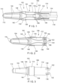
- a clipping device 100 for treating tissue defects comprises a clip 102 including a pair of clip arms 104, proximal ends 108 of which are slidably received within a capsule 106 so that the clip 102 may move between an open configuration, in which distal ends 110 of the clip arms 102 are separated from one another, and a closed configuration, in which the distal ends 110 are drawn toward one another.
- the capsule 106 further comprises a longitudinal body 112 and a cap 114 coupled to one another and movable relative to one another from a pre-deployed configuration to a deployed configuration.
- the cap 114 may be coupled to the longitudinal body 112 via, for example, a shear pin 132, which breaks or separates to move the capsule from the pre-deployed to the deployed configuration. As the capsule 106 is moved from the pre-deployed to the deployed configuration, the cap 114 moves relative to the longitudinal body 112 to reduce a length of the capsule 106 upon deployment.
- the device 100 is releasably coupled to a proximal portion 116 facilitating insertion of the device 100 to a target site, connecting the clip 102 to actuators accessible to a user (i.e., outside the body) to permit the user to control movement of the device 100 between the open and closed configurations and to deploy the device clip 102 over target tissue.
- the proximal portion 116 may include, for example, a flexible shaft 118 extending from a proximal end connected to a handle member (not shown) that remains outside the body, the handle including controls for moving and deploying the device 100 to a distal end 120 releasably coupled to a proximal end 122 of the capsule 106.
- the proximal portion 116 also includes a control member 124 extending from a proximal end connected to the controls of the handle member to a distal end 126 connected to the proximal ends 108 of the clip arms 102.
- the capsule 106 includes the longitudinal body 112 and the cap 114.
- the longitudinal body 112 extends from the proximal end 122 to a distal end 128 and includes a channel 130 extending therethrough.
- the proximal end 122 is configured to be releasably coupled to the distal end 120 of the flexible shaft 118.
- the proximal end 122 may include tabs 134 that are crimped radially inward to engage a corresponding portion of a bushing at the distal end 120 of the flexible shaft 118.
- the longitudinal body 112 may also include locking windows 136 extending laterally through a wall thereof or other structures for engaging locking tabs 150 of the clip arms 104, as will be described in further detail below.
- the cap 114 is mounted over the distal end 128 so that the cap 114 is movable relative to the longitudinal body 112 from the pre-deployed to the deployed configuration.
- the cap 114 also extends longitudinally from a proximal end 138 to a distal end 140 with a channel 142 extending longitudinally therethrough so that channels 142, 130 of the cap 114 and the longitudinal body 112 are aligned to permit the clip arms 104 to slide longitudinally therein.
- the cap 114 In the pre-deployed configuration, the cap 114 is in a distal-most position relative to the longitudinal body 112.
- the cap 114 moves proximally relative to the longitudinal body 112 so that a length of the capsule 106 in the deployed configuration is shorter than a length of the capsule 106 in the pre-deployed configuration.
- the distal end 140 of the cap 114 includes a shoulder 148 configured to engage the distal end 128 of the longitudinal body 112 to prevent the distal end 128 of the longitudinal body 112 from moving distally therepast.
- the shoulder 148 engages the distal end 128 of the longitudinal body 112
- the cap 114 is in a proximal-most position relative to the longitudinal body 112 and defines a minimum length of the capsule 106.
- the cap 114 may be coupled to the distal end 128 of the longitudinal body 112 in any of a variety of ways.
- the cap 114 may be overmolded to the longitudinal body 112.
- the cap 114 is overmolded to the distal end 128 of the longitudinal body 112 via a shear pin 132, in the pre-deployed configuration.
- the shear pin 132 is configured to break and/or separate when a predetermined force is exerted thereon.
- a portion of the one or both clip arms 104 engages the distal end 140 of the cap 114 so that a proximal force is exerted thereon.
- the proximal force exerted on the cap 114 breaks the shear pin 132 so that the cap 114 is freed to move proximally with respect to the longitudinal body 112, from the pre-deployed to the deployed configuration.
- Each of the clip arms 104 extends from the proximal end 108 to the distal end 110.
- proximal portions of the clip arms 104 are slidably received within the channels 130, 142 of the longitudinal body 112 and the cap 114 of the capsule 106.
- the proximal ends 108 of the clip arms 104 are slidably received within the longitudinal body 112 to move the clip 102 between the open and closed configurations.
- the proximal ends 108 of the clip arms 104 may be coupled to the control member 124 (directly or indirectly) so that the clip arms 104 may be moved between the open and closed configurations via manipulation of the control member 124.
- the clip arms 104 are biased toward the open configuration so that, in the closed configuration, the clip arms 104 are constrained toward one another via an interior surface of the cap 114 and/or the longitudinal body 112. When the clip arms 104 are moved distally to extend further out of the capsule 106, the clip arms 114 revert to their biased open configuration.
- Each of the clip arms 104 also includes an engaging feature 144 configured to engage a portion of the cap 114 to exert a proximal force thereon when the clip arms 104 are drawn proximally with respect to the capsule 106.
- the engaging features 144 extend from a portion of the clip arms 104 so that, when the clip arms 104 are drawn proximally relative to the capsule 106, the engaging features 144 abut a portion of a distal face 146 of the cap 114.
- the engaging features 144 are positioned along the clip arms 104 so that, when the engaging features 144 engage the cap 114, the clip arms 104 are drawn toward the closed configuration.
- the engaging features 144 are configured as wings extending from longitudinal edges of the clip arms 104.
- Proximal ends 108 of the clip arms 104 also include locking tabs 150 extending therefrom.
- the proximal ends 108 in this embodiment are biased outward, away from a centerline of the capsule 106, but are restrained via the distal end 126 of the control member 124 until the clip 102 is being deployed.
- the clip arms 104 are moved proximally relative to the capsule 106 until the proximal ends 108 of the clip arms 104 are released from the control member 124 and the locking tabs 150 are permitted to spring outward and engage the locking windows 136 of the longitudinal body 112.
- the clip 102 is inserted through, for example, a working channel of an endoscope to a target site within a body while the handle member remains exterior to the body.
- the clip 102 is inserted through the working channel in the closed configuration.
- the clip arms 104 are extended distally out of the capsule 106 and move under their natural bias toward the open configuration so that target tissue may be received between the clip arms 104.
- the clip 102 may be moved between the open and closed configurations by extending the control member 124 distally or withdrawing it proximally until a desired portion of target tissue is positioned between the clip arms 104, as desired.
- the clip 102 is drawn into the closed configuration to grip this portion of target tissue between the distal ends 110 of the clip arms 104 as desired.
- the clip 102 may be moved toward the locked configuration by, for example, drawing the control member 124 further proximally relative to the capsule 106 until the engaging features 144 engage the cap 114, as described above, exerting a proximal force on the cap 114 to break, separate or otherwise cause the shear pin 132 to fail.
- the cap 114 moves proximally relative to the longitudinal body 112 from the pre-deployed configuration to the deployed configuration, collapsing the capsule 106 and reducing a length of the capsule 106.
- the clip 102 is locked and deployed.
- the proximal force on the control member 124 causes the control member 124 to release from the proximal ends 108 of the clip arms 104, allowing the proximal ends 108 to revert to their biased configuration so that the locking tabs 150 engage the locking windows 136, thereby locking the clip 102 in the collapsed, closed configuration.
- the control member 124 is drawn proximally until an enlarged portion 152 at the distal end 126 of the control member 124 is positioned within the proximal end 122 of the longitudinal body 112 of the capsule 106 to move the inwardly crimped tabs 134 outward (i.e., away from a centerline of the capsule 106), out of engagement with, for example, the bushing at the distal end 120 of the flexible shaft 118. Further proximal motion of the control member 124 separates the control member 124 from the clip 102, freeing the clip 102 from the proximal portion of the device 100 and freeing it to remain in the body as the rest of the device 100 is removed from the body.
- the clip 102 may be deployed via any of a number of deployment mechanisms so long as the capsule 106 collapses to reduce a length thereof during the deployment process. Specifically, as described above, the capsule 106 is collapsed via the proximal motion of the cap 114 relative to the longitudinal body.
- the exemplary embodiment describes and shows mounting of the cap 114 over the distal end 128 of the longitudinal body 112 in the pre-deployed configuration via a shear pin 132, it will be understood by those of skill in the art that the cap 114 may be temporarily fixed relative to the longitudinal body 112 in the pre-deployed configuration and moved toward the deployed configuration via any of a number of mechanisms.
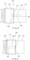
- a capsule 206 may be substantially similar to the capsule 106 described above, and may be utilized in place of the capsule 106 in the device 100.
- the capsule 206 includes a cap 214 mounted over a distal end 228 of a longitudinal body 212 and movable relative thereto from a pre-deployed configuration to a deployed configuration.
- the cap 214 and the longitudinal body 212 may be substantially similar to the cap 114 and longitudinal body 112 described above with respect to the capsule 106.
- the cap 214 is coupled to the longitudinal body 212 via a pin 232 and slot 254.
- a middle portion 260 of the slot 254 connecting the distal and proximal portions 256, 258 has a width smaller than a width of each of the distal and proximal portions 256, 258.
- a width of the middle portion 260 is smaller than a diameter of the pin 232 so that, to be moved from the pre-deployed to the deployed configuration, a predetermined force must be exerted on the pin 232, causing one of the pin 232 and/or the middle portion 260 to elastically deform allowing the pin 232 to slide along the middle portion 260 from the distal portion 256 to the proximal portion 258.
- the capsule 206 may be utilized in substantially the same manner as the capsule 106.
- the pin 232 in the pre-deployed configuration, is in the distal portion 256 of the slot 254 so that the cap 214 is in a distal-most position relative to the longitudinal body 212.
- the clip arms 104 are drawn farther proximally relative to the capsule 206 until the engaging features 144 of the clip arms 104 engage the cap 214, exerting a proximal force on the cap 214 which deforms the pin 232 or the middle portion 260 of the slot 254 permitting the pin 232 to slide from the distal portion 256, through the middle portion 260 and to the proximal portion 254.
- the cap 214 When the pin 232 is received within the proximal portion 254, the cap 214 is in the proximal-most position relative to the longitudinal body 212, in the collapsed configuration. As described above, the clip 102 may then be locked and deployed, in the collapsed and closed configuration, as will be understood by those of skill in the art.
Landscapes
- Health & Medical Sciences (AREA)
- Life Sciences & Earth Sciences (AREA)
- Surgery (AREA)
- Molecular Biology (AREA)
- General Health & Medical Sciences (AREA)
- Biomedical Technology (AREA)
- Heart & Thoracic Surgery (AREA)
- Medical Informatics (AREA)
- Nuclear Medicine, Radiotherapy & Molecular Imaging (AREA)
- Animal Behavior & Ethology (AREA)
- Engineering & Computer Science (AREA)
- Public Health (AREA)
- Veterinary Medicine (AREA)
- Reproductive Health (AREA)
- Vascular Medicine (AREA)
- Cardiology (AREA)
- Surgical Instruments (AREA)
Claims (10)
- Clipping-Vorrichtung, mit:einer Kapsel (106, 206), die einen sich in Längsrichtung erstreckenden Körper (112, 212) und eine Kappe (114, 214) aufweist, die über einem distalen Ende (128, 228) davon montiert ist, so dass die Kappe (114, 214) relativ zum sich in Längsrichtung erstreckenden Körper (112, 212) von einer vor-freigesetzten Konfiguration zu einer freigesetzten Konfiguration bewegbar ist, in der die Kappe (114, 214) proximal relativ zum sich in Längsrichtung erstreckenden Körper (112, 212) bewegt ist, um eine Länge der Kapsel (106, 206) zu reduzieren, wobei ein Kanal (142) der Kappe (114, 214) und ein Kanal (130) der Kapsel (106, 206) im Wesentlichen relativ zueinander ausgerichtet sind; undeinem Paar Clip-Armen (104), wobei zumindest proximale Abschnitte davon in den Kanälen (142, 130) der Kappe (114, 214) und des sich in Längsrichtung erstreckenden Körpers (112, 212) aufgenommen sind, so dass die Clip-Arme (104) relativ zur Kapsel (106, 206) zwischen einer offenen Konfiguration, in der distale Enden (110) der Clip-Arme (104) voneinander getrennt sind, und einer geschlossenen Konfiguration bewegbar sind, in der die distalen Enden (110) der Clip-Arme (104) zueinander hin gezogen sind.
- Vorrichtung nach Anspruch 1, wobei ein distales Ende der Kappe (114, 214) eine Schulter (148) aufweist, die dazu vorgesehen ist, am distalen Ende (128, 228) des sich in Längsrichtung erstreckenden Körpers (112, 212) anzuliegen, um eine weitere proximale Bewegung der Kappe (114, 214) relativ zum sich in Längsrichtung erstreckenden Körper (112, 212) zu verhindern.
- Vorrichtung nach Anspruch 1 oder 2, wobei die Clip-Arme (104) in Richtung zur offenen Konfiguration vorgespannt sind, so dass die Clip-Arme (104) in der geschlossenen Konfiguration durch einen Kontakt mit einer Innenfläche entweder der Kappe (114, 214) oder des sich in Längsrichtung erstreckenden Körpers (112, 212) zueinander hin gezogen werden.
- Vorrichtung nach einem der Ansprüche 1 bis 3, wobei ein proximaler Abschnitt des sich in Längsrichtung erstreckenden Körpers (112, 212) sich durch eine Wand davon erstreckende Verriegelungsfenster (136) aufweist.
- Vorrichtung nach Anspruch 4, wobei proximale Enden der Clip-Arme (104) Verriegelungslaschen (150) aufweisen, die dafür konfiguriert sind, mit den Verriegelungsfenstern (136) des sich in Längsrichtung erstreckenden Körpers (112, 212) in Eingriff zu kommen, wenn sich die Kapsel (106, 206) in der freigesetzten Konfiguration befindet.
- Vorrichtung nach einem der Ansprüche 1 bis 5, wobei die Kappe (114) mit dem sich in Längsrichtung erstreckenden Körper (112) über einen Scherstift (132) verbunden ist, der derart konfiguriert ist, dass er bricht, wenn eine vorgegebene Kraft auf ihn ausgeübt wird.
- Vorrichtung nach einem der Ansprüche 1 bis 5, wobei die Kappe (214) mit dem sich in Längsrichtung erstreckenden Körper (212) über einen Stift (232) verbunden ist, der sich von einer Innenfläche davon und durch eine Schlitzöffnung (254) erstreckt, die sich durch eine Wand entlang eines distalen Abschnitts des sich in Längsrichtung erstreckenden Körpers (212) erstreckt, wobei der Stift in Längsrichtung von einem distalen Ende (256) der Schlitzöffnung (254) in der vor-freigesetzten Konfiguration zu einem proximalen Ende (258) der Schlitzöffnung (254) in der freigesetzten Konfiguration verschiebbar ist.
- Vorrichtung nach Anspruch 7, wenn ferner abhängig von einem der Ansprüche 2 bis 5, wobei das distale Ende (256) der Schlitzöffnung (254) derart dimensioniert und geformt ist, dass es einer Größe und einer Form des Stifts (232) entspricht, wobei das distale und das proximale Ende (256, 258) der Schlitzöffnung (254) über einen mittleren Abschnitt (260) verbunden sind, der eine geringere Breite hat als das distale Ende (256) der Schlitzöffnung (254), so dass, wenn eine vorgegebene Kraft auf die Kappe (214) ausgeübt wird, um die Kapsel (206) von der vor-freigesetzten in die freigesetzte Konfiguration zu bewegen, entweder der Stift (232) oder der mittlere Abschnitt (260) sich verformen, um zu ermöglichen, dass der Stift (232) proximal entlang der Schlitzöffnung (254) gleiten kann.
- Vorrichtung nach einem der Ansprüche 1 bis 8, wobei mindestens einer der Clip-Arme (104) ein Eingriffsmerkmal (144) aufweist, das dafür konfiguriert ist, mit einem Abschnitt der Kappe (114, 214) in Eingriff zu kommen, so dass, wenn eine vorgegebene proximale Kraft darauf ausgeübt wird, die Kapsel (106, 206) von der vor-freigesetzten Konfiguration in die freigesetzte Konfiguration bewegt wird.
- Vorrichtung nach einem der Ansprüche 1 bis 9,
wobei die Vorrichtung ferner einen proximalen Abschnitt (116) aufweist, der dafür konfiguriert ist, das Einführen des Clips durch einen Arbeitskanal eines Endoskops zu ermöglichen, wobei der proximale Abschnitt (116) einen flexiblen Schaft (118), der sich von einem proximalen Ende zu einem distalen Ende erstreckt und dafür konfiguriert ist, lösbar mit dem proximalen Ende der Kapsel (106, 206) verbunden zu werden, und ein Steuerelement (124) aufweist, das sich durch den flexiblen Schaft (118) zu einem distalen Ende erstreckt, wobei das Steuerelement (124) lösbar mit den proximalen Enden der Clip-Arme (104) verbunden ist, so dass ein Bewegen des Steuerelements (124) in Längsrichtung relativ zum flexiblen Schaft (118) die Clip-Arme (104) zwischen der offenen und der geschlossenen Konfiguration bewegt.
Priority Applications (3)
| Application Number | Priority Date | Filing Date | Title |
|---|---|---|---|
| EP23162718.3A EP4218615B1 (de) | 2019-05-28 | 2020-04-28 | Hämostaseclip mit zusammenklappbarer kapsel |
| EP21216861.1A EP4049595B1 (de) | 2019-05-28 | 2020-04-28 | Hämostase-clip mit kollabierbarer kapsel |
| EP25171617.1A EP4595917A3 (de) | 2019-05-28 | 2020-04-28 | Hämostaseclip mit zusammenklappbarer kapsel |
Applications Claiming Priority (2)
| Application Number | Priority Date | Filing Date | Title |
|---|---|---|---|
| US201962853303P | 2019-05-28 | 2019-05-28 | |
| PCT/US2020/030308 WO2020242698A1 (en) | 2019-05-28 | 2020-04-28 | Hemostasis clip with collapsible capsule |
Related Child Applications (6)
| Application Number | Title | Priority Date | Filing Date |
|---|---|---|---|
| EP23162718.3A Division EP4218615B1 (de) | 2019-05-28 | 2020-04-28 | Hämostaseclip mit zusammenklappbarer kapsel |
| EP23162718.3A Division-Into EP4218615B1 (de) | 2019-05-28 | 2020-04-28 | Hämostaseclip mit zusammenklappbarer kapsel |
| EP21216861.1A Division EP4049595B1 (de) | 2019-05-28 | 2020-04-28 | Hämostase-clip mit kollabierbarer kapsel |
| EP21216861.1A Division-Into EP4049595B1 (de) | 2019-05-28 | 2020-04-28 | Hämostase-clip mit kollabierbarer kapsel |
| EP25171617.1A Division-Into EP4595917A3 (de) | 2019-05-28 | 2020-04-28 | Hämostaseclip mit zusammenklappbarer kapsel |
| EP25171617.1A Division EP4595917A3 (de) | 2019-05-28 | 2020-04-28 | Hämostaseclip mit zusammenklappbarer kapsel |
Publications (2)
| Publication Number | Publication Date |
|---|---|
| EP3897406A1 EP3897406A1 (de) | 2021-10-27 |
| EP3897406B1 true EP3897406B1 (de) | 2025-06-11 |
Family
ID=70779888
Family Applications (4)
| Application Number | Title | Priority Date | Filing Date |
|---|---|---|---|
| EP21216861.1A Active EP4049595B1 (de) | 2019-05-28 | 2020-04-28 | Hämostase-clip mit kollabierbarer kapsel |
| EP25171617.1A Pending EP4595917A3 (de) | 2019-05-28 | 2020-04-28 | Hämostaseclip mit zusammenklappbarer kapsel |
| EP20727456.4A Active EP3897406B1 (de) | 2019-05-28 | 2020-04-28 | Hämostase-clip mit zusammenklappbarer kapsel |
| EP23162718.3A Active EP4218615B1 (de) | 2019-05-28 | 2020-04-28 | Hämostaseclip mit zusammenklappbarer kapsel |
Family Applications Before (2)
| Application Number | Title | Priority Date | Filing Date |
|---|---|---|---|
| EP21216861.1A Active EP4049595B1 (de) | 2019-05-28 | 2020-04-28 | Hämostase-clip mit kollabierbarer kapsel |
| EP25171617.1A Pending EP4595917A3 (de) | 2019-05-28 | 2020-04-28 | Hämostaseclip mit zusammenklappbarer kapsel |
Family Applications After (1)
| Application Number | Title | Priority Date | Filing Date |
|---|---|---|---|
| EP23162718.3A Active EP4218615B1 (de) | 2019-05-28 | 2020-04-28 | Hämostaseclip mit zusammenklappbarer kapsel |
Country Status (8)
| Country | Link |
|---|---|
| US (4) | US11234686B2 (de) |
| EP (4) | EP4049595B1 (de) |
| JP (1) | JP7153806B2 (de) |
| KR (2) | KR102757358B1 (de) |
| CN (1) | CN113747846B (de) |
| AU (1) | AU2020283437B2 (de) |
| CA (1) | CA3129900C (de) |
| WO (1) | WO2020242698A1 (de) |
Families Citing this family (5)
| Publication number | Priority date | Publication date | Assignee | Title |
|---|---|---|---|---|
| CA3129900C (en) * | 2019-05-28 | 2023-08-22 | Boston Scientific Scimed, Inc. | Hemostasis clip with collapsible capsule |
| JP7230229B2 (ja) * | 2019-05-28 | 2023-02-28 | ボストン サイエンティフィック サイムド,インコーポレイテッド | 止血クリップの配備 |
| AU2022313786B2 (en) | 2021-07-20 | 2024-10-10 | Boston Scientific Medical Device Limited | Over the scope clip with repositional capability |
| WO2024072629A1 (en) * | 2022-09-27 | 2024-04-04 | Boston Scientific Scimed, Inc. | Locking feature for hemostasis clip |
| EP4676301A1 (de) * | 2023-08-18 | 2026-01-14 | Boston Scientific Scimed Inc. | Ausziehbare und einziehbare endoskopische kappe |
Family Cites Families (16)
| Publication number | Priority date | Publication date | Assignee | Title |
|---|---|---|---|---|
| JPS5320957Y2 (de) * | 1973-11-14 | 1978-06-01 | ||
| AU2004289214B2 (en) * | 2003-11-07 | 2011-05-19 | Scimed Life Systems, Inc. | Endoscopic hemoscopic clipping apparatus |
| JP4116049B2 (ja) * | 2006-07-25 | 2008-07-09 | オリンパスメディカルシステムズ株式会社 | 生体組織のクリップ装置 |
| JP4160608B2 (ja) * | 2006-08-03 | 2008-10-01 | オリンパスメディカルシステムズ株式会社 | 内視鏡用処置具 |
| JP2008307168A (ja) * | 2007-06-13 | 2008-12-25 | Hoya Corp | 内視鏡用クリップ装置 |
| EP2630923B1 (de) * | 2008-06-19 | 2015-02-11 | Boston Scientific Scimed, Inc. | Blutstillende Klemmsetzvorrichtungen |
| WO2012151415A1 (en) * | 2011-05-04 | 2012-11-08 | Boston Scientific Scimed, Inc. | Through the scope tension member release clip |
| US9265486B2 (en) * | 2011-08-15 | 2016-02-23 | Atricure, Inc. | Surgical device |
| JP6052010B2 (ja) * | 2013-03-28 | 2016-12-27 | 住友ベークライト株式会社 | 生体組織のクリップ装置 |
| CA3027258C (en) * | 2016-08-22 | 2021-01-05 | Boston Scientific Limited | Hemostasis reloadable clipping device with sleeve engagement |
| EP3915494B1 (de) * | 2016-09-22 | 2025-07-16 | Boston Scientific Limited | Mehrfaches öffnen/schliessen einer klemme |
| CN109788957B (zh) * | 2016-09-29 | 2023-01-13 | 波士顿科学有限公司 | 用于可重新加载的止血夹紧装置的牺牲联接器 |
| EP4218620B1 (de) * | 2016-10-06 | 2026-04-15 | Boston Scientific Scimed, Inc. | Teilweise ovale kapsel für nachladbare hämostaseklemmvorrichtung |
| CN109922743B (zh) * | 2016-11-22 | 2021-12-14 | 波士顿科学有限公司 | 止血可重新加载的夹子释放机构 |
| KR20200026961A (ko) * | 2017-10-11 | 2020-03-11 | 보스톤 싸이엔티픽 싸이메드 인코포레이티드 | 강화된 기계적 지혈 클립 |
| CA3129900C (en) * | 2019-05-28 | 2023-08-22 | Boston Scientific Scimed, Inc. | Hemostasis clip with collapsible capsule |
-
2020
- 2020-04-28 CA CA3129900A patent/CA3129900C/en active Active
- 2020-04-28 EP EP21216861.1A patent/EP4049595B1/de active Active
- 2020-04-28 CN CN202080029513.9A patent/CN113747846B/zh active Active
- 2020-04-28 KR KR1020247005921A patent/KR102757358B1/ko active Active
- 2020-04-28 JP JP2021549756A patent/JP7153806B2/ja active Active
- 2020-04-28 EP EP25171617.1A patent/EP4595917A3/de active Pending
- 2020-04-28 EP EP20727456.4A patent/EP3897406B1/de active Active
- 2020-04-28 US US16/861,086 patent/US11234686B2/en active Active
- 2020-04-28 AU AU2020283437A patent/AU2020283437B2/en active Active
- 2020-04-28 KR KR1020217025334A patent/KR102640820B1/ko active Active
- 2020-04-28 WO PCT/US2020/030308 patent/WO2020242698A1/en not_active Ceased
- 2020-04-28 EP EP23162718.3A patent/EP4218615B1/de active Active
-
2021
- 2021-12-20 US US17/645,250 patent/US11849930B2/en active Active
-
2023
- 2023-11-15 US US18/510,296 patent/US12262883B2/en active Active
-
2025
- 2025-02-27 US US19/065,709 patent/US20250195056A1/en active Pending
Also Published As
| Publication number | Publication date |
|---|---|
| US11849930B2 (en) | 2023-12-26 |
| AU2020283437B2 (en) | 2022-05-19 |
| AU2020283437A1 (en) | 2021-08-05 |
| US11234686B2 (en) | 2022-02-01 |
| US20220110618A1 (en) | 2022-04-14 |
| CN113747846A (zh) | 2021-12-03 |
| US12262883B2 (en) | 2025-04-01 |
| CN113747846B (zh) | 2025-02-21 |
| US20240081799A1 (en) | 2024-03-14 |
| EP4218615A1 (de) | 2023-08-02 |
| KR20240028559A (ko) | 2024-03-05 |
| EP4218615B1 (de) | 2025-07-09 |
| EP4049595A1 (de) | 2022-08-31 |
| EP3897406A1 (de) | 2021-10-27 |
| EP4595917A3 (de) | 2025-10-08 |
| EP4049595B1 (de) | 2023-12-13 |
| US20250195056A1 (en) | 2025-06-19 |
| WO2020242698A1 (en) | 2020-12-03 |
| CA3129900A1 (en) | 2020-12-03 |
| KR20210127933A (ko) | 2021-10-25 |
| JP7153806B2 (ja) | 2022-10-14 |
| JP2022522671A (ja) | 2022-04-20 |
| CA3129900C (en) | 2023-08-22 |
| KR102640820B1 (ko) | 2024-02-27 |
| US20200375583A1 (en) | 2020-12-03 |
| EP4595917A2 (de) | 2025-08-06 |
| KR102757358B1 (ko) | 2025-01-21 |
Similar Documents
| Publication | Publication Date | Title |
|---|---|---|
| EP3897406B1 (de) | Hämostase-clip mit zusammenklappbarer kapsel | |
| US11896235B2 (en) | Hemostasis clip deployment | |
| US12076015B2 (en) | Hemostasis clip short system | |
| EP4035610B1 (de) | Hämostase-clip mit zweistufigem einsatzmechanismus zur beseitigung von ablösenden teilen | |
| EP3937798B1 (de) | Federbelasteter mechanismus zum entfalten eines hämostatischen clips |
Legal Events
| Date | Code | Title | Description |
|---|---|---|---|
| STAA | Information on the status of an ep patent application or granted ep patent |
Free format text: STATUS: UNKNOWN |
|
| STAA | Information on the status of an ep patent application or granted ep patent |
Free format text: STATUS: THE INTERNATIONAL PUBLICATION HAS BEEN MADE |
|
| PUAI | Public reference made under article 153(3) epc to a published international application that has entered the european phase |
Free format text: ORIGINAL CODE: 0009012 |
|
| STAA | Information on the status of an ep patent application or granted ep patent |
Free format text: STATUS: REQUEST FOR EXAMINATION WAS MADE |
|
| 17P | Request for examination filed |
Effective date: 20210721 |
|
| AK | Designated contracting states |
Kind code of ref document: A1 Designated state(s): AL AT BE BG CH CY CZ DE DK EE ES FI FR GB GR HR HU IE IS IT LI LT LU LV MC MK MT NL NO PL PT RO RS SE SI SK SM TR |
|
| RIC1 | Information provided on ipc code assigned before grant |
Ipc: A61B 90/00 20160101ALI20220629BHEP Ipc: A61B 17/128 20060101ALI20220629BHEP Ipc: A61B 17/122 20060101ALI20220629BHEP Ipc: A61B 17/08 20060101AFI20220629BHEP |
|
| GRAP | Despatch of communication of intention to grant a patent |
Free format text: ORIGINAL CODE: EPIDOSNIGR1 |
|
| STAA | Information on the status of an ep patent application or granted ep patent |
Free format text: STATUS: GRANT OF PATENT IS INTENDED |
|
| DAV | Request for validation of the european patent (deleted) | ||
| DAX | Request for extension of the european patent (deleted) | ||
| INTG | Intention to grant announced |
Effective date: 20220822 |
|
| RAP3 | Party data changed (applicant data changed or rights of an application transferred) |
Owner name: BOSTON SCIENTIFIC SCIMED, INC. |
|
| GRAJ | Information related to disapproval of communication of intention to grant by the applicant or resumption of examination proceedings by the epo deleted |
Free format text: ORIGINAL CODE: EPIDOSDIGR1 |
|
| STAA | Information on the status of an ep patent application or granted ep patent |
Free format text: STATUS: REQUEST FOR EXAMINATION WAS MADE |
|
| STAA | Information on the status of an ep patent application or granted ep patent |
Free format text: STATUS: EXAMINATION IS IN PROGRESS |
|
| INTC | Intention to grant announced (deleted) | ||
| 17Q | First examination report despatched |
Effective date: 20230104 |
|
| GRAP | Despatch of communication of intention to grant a patent |
Free format text: ORIGINAL CODE: EPIDOSNIGR1 |
|
| STAA | Information on the status of an ep patent application or granted ep patent |
Free format text: STATUS: GRANT OF PATENT IS INTENDED |
|
| INTG | Intention to grant announced |
Effective date: 20230706 |
|
| GRAJ | Information related to disapproval of communication of intention to grant by the applicant or resumption of examination proceedings by the epo deleted |
Free format text: ORIGINAL CODE: EPIDOSDIGR1 |
|
| STAA | Information on the status of an ep patent application or granted ep patent |
Free format text: STATUS: EXAMINATION IS IN PROGRESS |
|
| INTC | Intention to grant announced (deleted) | ||
| GRAP | Despatch of communication of intention to grant a patent |
Free format text: ORIGINAL CODE: EPIDOSNIGR1 |
|
| STAA | Information on the status of an ep patent application or granted ep patent |
Free format text: STATUS: GRANT OF PATENT IS INTENDED |
|
| INTG | Intention to grant announced |
Effective date: 20250304 |
|
| GRAS | Grant fee paid |
Free format text: ORIGINAL CODE: EPIDOSNIGR3 |
|
| GRAA | (expected) grant |
Free format text: ORIGINAL CODE: 0009210 |
|
| STAA | Information on the status of an ep patent application or granted ep patent |
Free format text: STATUS: THE PATENT HAS BEEN GRANTED |
|
| AK | Designated contracting states |
Kind code of ref document: B1 Designated state(s): AL AT BE BG CH CY CZ DE DK EE ES FI FR GB GR HR HU IE IS IT LI LT LU LV MC MK MT NL NO PL PT RO RS SE SI SK SM TR |
|
| REG | Reference to a national code |
Ref country code: GB Ref legal event code: FG4D |
|
| REG | Reference to a national code |
Ref country code: CH Ref legal event code: EP |
|
| REG | Reference to a national code |
Ref country code: IE Ref legal event code: FG4D |
|
| REG | Reference to a national code |
Ref country code: DE Ref legal event code: R096 Ref document number: 602020052605 Country of ref document: DE |
|
| REG | Reference to a national code |
Ref country code: NL Ref legal event code: FP |
|
| PG25 | Lapsed in a contracting state [announced via postgrant information from national office to epo] |
Ref country code: ES Free format text: LAPSE BECAUSE OF FAILURE TO SUBMIT A TRANSLATION OF THE DESCRIPTION OR TO PAY THE FEE WITHIN THE PRESCRIBED TIME-LIMIT Effective date: 20250611 Ref country code: FI Free format text: LAPSE BECAUSE OF FAILURE TO SUBMIT A TRANSLATION OF THE DESCRIPTION OR TO PAY THE FEE WITHIN THE PRESCRIBED TIME-LIMIT Effective date: 20250611 |
|
| REG | Reference to a national code |
Ref country code: LT Ref legal event code: MG9D |
|
| PG25 | Lapsed in a contracting state [announced via postgrant information from national office to epo] |
Ref country code: NO Free format text: LAPSE BECAUSE OF FAILURE TO SUBMIT A TRANSLATION OF THE DESCRIPTION OR TO PAY THE FEE WITHIN THE PRESCRIBED TIME-LIMIT Effective date: 20250911 Ref country code: GR Free format text: LAPSE BECAUSE OF FAILURE TO SUBMIT A TRANSLATION OF THE DESCRIPTION OR TO PAY THE FEE WITHIN THE PRESCRIBED TIME-LIMIT Effective date: 20250912 |
|
| PG25 | Lapsed in a contracting state [announced via postgrant information from national office to epo] |
Ref country code: BG Free format text: LAPSE BECAUSE OF FAILURE TO SUBMIT A TRANSLATION OF THE DESCRIPTION OR TO PAY THE FEE WITHIN THE PRESCRIBED TIME-LIMIT Effective date: 20250611 |
|
| PG25 | Lapsed in a contracting state [announced via postgrant information from national office to epo] |
Ref country code: HR Free format text: LAPSE BECAUSE OF FAILURE TO SUBMIT A TRANSLATION OF THE DESCRIPTION OR TO PAY THE FEE WITHIN THE PRESCRIBED TIME-LIMIT Effective date: 20250611 |
|
| PG25 | Lapsed in a contracting state [announced via postgrant information from national office to epo] |
Ref country code: RS Free format text: LAPSE BECAUSE OF FAILURE TO SUBMIT A TRANSLATION OF THE DESCRIPTION OR TO PAY THE FEE WITHIN THE PRESCRIBED TIME-LIMIT Effective date: 20250911 |
|
| PG25 | Lapsed in a contracting state [announced via postgrant information from national office to epo] |
Ref country code: LV Free format text: LAPSE BECAUSE OF FAILURE TO SUBMIT A TRANSLATION OF THE DESCRIPTION OR TO PAY THE FEE WITHIN THE PRESCRIBED TIME-LIMIT Effective date: 20250611 |
|
| PG25 | Lapsed in a contracting state [announced via postgrant information from national office to epo] |
Ref country code: PT Free format text: LAPSE BECAUSE OF FAILURE TO SUBMIT A TRANSLATION OF THE DESCRIPTION OR TO PAY THE FEE WITHIN THE PRESCRIBED TIME-LIMIT Effective date: 20251013 |
|
| REG | Reference to a national code |
Ref country code: AT Ref legal event code: MK05 Ref document number: 1801753 Country of ref document: AT Kind code of ref document: T Effective date: 20250611 |
|
| PG25 | Lapsed in a contracting state [announced via postgrant information from national office to epo] |
Ref country code: IS Free format text: LAPSE BECAUSE OF FAILURE TO SUBMIT A TRANSLATION OF THE DESCRIPTION OR TO PAY THE FEE WITHIN THE PRESCRIBED TIME-LIMIT Effective date: 20251011 |
|
| PG25 | Lapsed in a contracting state [announced via postgrant information from national office to epo] |
Ref country code: SM Free format text: LAPSE BECAUSE OF FAILURE TO SUBMIT A TRANSLATION OF THE DESCRIPTION OR TO PAY THE FEE WITHIN THE PRESCRIBED TIME-LIMIT Effective date: 20250611 Ref country code: AT Free format text: LAPSE BECAUSE OF FAILURE TO SUBMIT A TRANSLATION OF THE DESCRIPTION OR TO PAY THE FEE WITHIN THE PRESCRIBED TIME-LIMIT Effective date: 20250611 |
|
| PG25 | Lapsed in a contracting state [announced via postgrant information from national office to epo] |
Ref country code: CZ Free format text: LAPSE BECAUSE OF FAILURE TO SUBMIT A TRANSLATION OF THE DESCRIPTION OR TO PAY THE FEE WITHIN THE PRESCRIBED TIME-LIMIT Effective date: 20250611 |
|
| PG25 | Lapsed in a contracting state [announced via postgrant information from national office to epo] |
Ref country code: PL Free format text: LAPSE BECAUSE OF FAILURE TO SUBMIT A TRANSLATION OF THE DESCRIPTION OR TO PAY THE FEE WITHIN THE PRESCRIBED TIME-LIMIT Effective date: 20250611 |
|
| PG25 | Lapsed in a contracting state [announced via postgrant information from national office to epo] |
Ref country code: EE Free format text: LAPSE BECAUSE OF FAILURE TO SUBMIT A TRANSLATION OF THE DESCRIPTION OR TO PAY THE FEE WITHIN THE PRESCRIBED TIME-LIMIT Effective date: 20250611 |
|
| PG25 | Lapsed in a contracting state [announced via postgrant information from national office to epo] |
Ref country code: SK Free format text: LAPSE BECAUSE OF FAILURE TO SUBMIT A TRANSLATION OF THE DESCRIPTION OR TO PAY THE FEE WITHIN THE PRESCRIBED TIME-LIMIT Effective date: 20250611 Ref country code: RO Free format text: LAPSE BECAUSE OF FAILURE TO SUBMIT A TRANSLATION OF THE DESCRIPTION OR TO PAY THE FEE WITHIN THE PRESCRIBED TIME-LIMIT Effective date: 20250611 |
|
| PGFP | Annual fee paid to national office [announced via postgrant information from national office to epo] |
Ref country code: GB Payment date: 20260319 Year of fee payment: 7 |
|
| PG25 | Lapsed in a contracting state [announced via postgrant information from national office to epo] |
Ref country code: DK Free format text: LAPSE BECAUSE OF FAILURE TO SUBMIT A TRANSLATION OF THE DESCRIPTION OR TO PAY THE FEE WITHIN THE PRESCRIBED TIME-LIMIT Effective date: 20250611 |
|
| PGFP | Annual fee paid to national office [announced via postgrant information from national office to epo] |
Ref country code: IE Payment date: 20260320 Year of fee payment: 7 |
|
| PG25 | Lapsed in a contracting state [announced via postgrant information from national office to epo] |
Ref country code: IT Free format text: LAPSE BECAUSE OF FAILURE TO SUBMIT A TRANSLATION OF THE DESCRIPTION OR TO PAY THE FEE WITHIN THE PRESCRIBED TIME-LIMIT Effective date: 20250611 |
|
| PGFP | Annual fee paid to national office [announced via postgrant information from national office to epo] |
Ref country code: NL Payment date: 20260319 Year of fee payment: 7 |
|
| PLBE | No opposition filed within time limit |
Free format text: ORIGINAL CODE: 0009261 |
|
| STAA | Information on the status of an ep patent application or granted ep patent |
Free format text: STATUS: NO OPPOSITION FILED WITHIN TIME LIMIT |
|
| REG | Reference to a national code |
Ref country code: CH Ref legal event code: L10 Free format text: ST27 STATUS EVENT CODE: U-0-0-L10-L00 (AS PROVIDED BY THE NATIONAL OFFICE) Effective date: 20260423 |