EP3896005A1 - Product delivery system and installation method thereof, and product delivery method - Google Patents
Product delivery system and installation method thereof, and product delivery method Download PDFInfo
- Publication number
- EP3896005A1 EP3896005A1 EP18942920.2A EP18942920A EP3896005A1 EP 3896005 A1 EP3896005 A1 EP 3896005A1 EP 18942920 A EP18942920 A EP 18942920A EP 3896005 A1 EP3896005 A1 EP 3896005A1
- Authority
- EP
- European Patent Office
- Prior art keywords
- parcel
- storage box
- assembly
- opening
- transport
- Prior art date
- Legal status (The legal status is an assumption and is not a legal conclusion. Google has not performed a legal analysis and makes no representation as to the accuracy of the status listed.)
- Pending
Links
- 238000000034 method Methods 0.000 title claims description 28
- 238000002716 delivery method Methods 0.000 title 1
- 238000009434 installation Methods 0.000 title 1
- 238000012546 transfer Methods 0.000 claims abstract description 79
- 230000005611 electricity Effects 0.000 claims description 2
- 230000005540 biological transmission Effects 0.000 description 18
- 238000010586 diagram Methods 0.000 description 10
- 230000000712 assembly Effects 0.000 description 5
- 238000000429 assembly Methods 0.000 description 5
- 238000013459 approach Methods 0.000 description 3
- 230000001681 protective effect Effects 0.000 description 3
- 230000008602 contraction Effects 0.000 description 2
- 238000010276 construction Methods 0.000 description 1
- 238000011161 development Methods 0.000 description 1
- 238000005516 engineering process Methods 0.000 description 1
- 238000012986 modification Methods 0.000 description 1
- 230000004048 modification Effects 0.000 description 1
- 230000004584 weight gain Effects 0.000 description 1
- 235000019786 weight gain Nutrition 0.000 description 1
Images


Classifications
-
- B—PERFORMING OPERATIONS; TRANSPORTING
- B65—CONVEYING; PACKING; STORING; HANDLING THIN OR FILAMENTARY MATERIAL
- B65G—TRANSPORT OR STORAGE DEVICES, e.g. CONVEYORS FOR LOADING OR TIPPING, SHOP CONVEYOR SYSTEMS OR PNEUMATIC TUBE CONVEYORS
- B65G35/00—Mechanical conveyors not otherwise provided for
-
- B—PERFORMING OPERATIONS; TRANSPORTING
- B64—AIRCRAFT; AVIATION; COSMONAUTICS
- B64F—GROUND OR AIRCRAFT-CARRIER-DECK INSTALLATIONS SPECIALLY ADAPTED FOR USE IN CONNECTION WITH AIRCRAFT; DESIGNING, MANUFACTURING, ASSEMBLING, CLEANING, MAINTAINING OR REPAIRING AIRCRAFT, NOT OTHERWISE PROVIDED FOR; HANDLING, TRANSPORTING, TESTING OR INSPECTING AIRCRAFT COMPONENTS, NOT OTHERWISE PROVIDED FOR
- B64F1/00—Ground or aircraft-carrier-deck installations
- B64F1/32—Ground or aircraft-carrier-deck installations for handling freight
-
- B—PERFORMING OPERATIONS; TRANSPORTING
- B64—AIRCRAFT; AVIATION; COSMONAUTICS
- B64C—AEROPLANES; HELICOPTERS
- B64C39/00—Aircraft not otherwise provided for
- B64C39/02—Aircraft not otherwise provided for characterised by special use
- B64C39/024—Aircraft not otherwise provided for characterised by special use of the remote controlled vehicle type, i.e. RPV
-
- B—PERFORMING OPERATIONS; TRANSPORTING
- B64—AIRCRAFT; AVIATION; COSMONAUTICS
- B64U—UNMANNED AERIAL VEHICLES [UAV]; EQUIPMENT THEREFOR
- B64U10/00—Type of UAV
- B64U10/10—Rotorcrafts
- B64U10/13—Flying platforms
- B64U10/14—Flying platforms with four distinct rotor axes, e.g. quadcopters
-
- B—PERFORMING OPERATIONS; TRANSPORTING
- B64—AIRCRAFT; AVIATION; COSMONAUTICS
- B64U—UNMANNED AERIAL VEHICLES [UAV]; EQUIPMENT THEREFOR
- B64U70/00—Launching, take-off or landing arrangements
- B64U70/90—Launching from or landing on platforms
-
- B—PERFORMING OPERATIONS; TRANSPORTING
- B65—CONVEYING; PACKING; STORING; HANDLING THIN OR FILAMENTARY MATERIAL
- B65G—TRANSPORT OR STORAGE DEVICES, e.g. CONVEYORS FOR LOADING OR TIPPING, SHOP CONVEYOR SYSTEMS OR PNEUMATIC TUBE CONVEYORS
- B65G1/00—Storing articles, individually or in orderly arrangement, in warehouses or magazines
- B65G1/02—Storage devices
- B65G1/04—Storage devices mechanical
-
- B—PERFORMING OPERATIONS; TRANSPORTING
- B65—CONVEYING; PACKING; STORING; HANDLING THIN OR FILAMENTARY MATERIAL
- B65G—TRANSPORT OR STORAGE DEVICES, e.g. CONVEYORS FOR LOADING OR TIPPING, SHOP CONVEYOR SYSTEMS OR PNEUMATIC TUBE CONVEYORS
- B65G47/00—Article or material-handling devices associated with conveyors; Methods employing such devices
- B65G47/22—Devices influencing the relative position or the attitude of articles during transit by conveyors
-
- B—PERFORMING OPERATIONS; TRANSPORTING
- B65—CONVEYING; PACKING; STORING; HANDLING THIN OR FILAMENTARY MATERIAL
- B65G—TRANSPORT OR STORAGE DEVICES, e.g. CONVEYORS FOR LOADING OR TIPPING, SHOP CONVEYOR SYSTEMS OR PNEUMATIC TUBE CONVEYORS
- B65G47/00—Article or material-handling devices associated with conveyors; Methods employing such devices
- B65G47/74—Feeding, transfer, or discharging devices of particular kinds or types
-
- B—PERFORMING OPERATIONS; TRANSPORTING
- B64—AIRCRAFT; AVIATION; COSMONAUTICS
- B64D—EQUIPMENT FOR FITTING IN OR TO AIRCRAFT; FLIGHT SUITS; PARACHUTES; ARRANGEMENTS OR MOUNTING OF POWER PLANTS OR PROPULSION TRANSMISSIONS IN AIRCRAFT
- B64D1/00—Dropping, ejecting, releasing, or receiving articles, liquids, or the like, in flight
- B64D1/22—Taking-up articles from earth's surface
-
- B—PERFORMING OPERATIONS; TRANSPORTING
- B64—AIRCRAFT; AVIATION; COSMONAUTICS
- B64U—UNMANNED AERIAL VEHICLES [UAV]; EQUIPMENT THEREFOR
- B64U2101/00—UAVs specially adapted for particular uses or applications
- B64U2101/60—UAVs specially adapted for particular uses or applications for transporting passengers; for transporting goods other than weapons
- B64U2101/64—UAVs specially adapted for particular uses or applications for transporting passengers; for transporting goods other than weapons for parcel delivery or retrieval
-
- B—PERFORMING OPERATIONS; TRANSPORTING
- B65—CONVEYING; PACKING; STORING; HANDLING THIN OR FILAMENTARY MATERIAL
- B65G—TRANSPORT OR STORAGE DEVICES, e.g. CONVEYORS FOR LOADING OR TIPPING, SHOP CONVEYOR SYSTEMS OR PNEUMATIC TUBE CONVEYORS
- B65G2201/00—Indexing codes relating to handling devices, e.g. conveyors, characterised by the type of product or load being conveyed or handled
- B65G2201/02—Articles
Definitions
- the present disclosure relates to a parcel transport system, an installing method thereof and methods for delivering a parcel.
- unmanned aerial vehicles and unmanned ground vehicles have been applied to a parcel delivery in an express delivery industry.
- intelligent equipment such as the unmanned aerial vehicle and the unmanned ground vehicle is difficult to implement home delivery, thus it is still inconvenient for users to receive and send the parcels, especially for users who stay in multi-storey buildings.
- the present disclosure proposes a parcel transport system which makes the parcel delivery more convenient and is capable of being applied to a multi-storey building.
- the present disclosure also proposes a method for installing the parcel transport system and methods for delivering a parcel.
- a parcel transport system comprises: an interface assembly used for a parcel transfer to or from an external equipment; a storage assembly comprising a storage box used for accommodating the parcel, wherein the storage box is provided with a first access opening and a second access opening, and the storage box is movable to enable the first access opening to be exposed and to be blocked; and a transport assembly capable of transporting the parcel, wherein the transport assembly is capable of reaching into the storage box via the second access opening, enabling the transport assembly to move the parcel into or out of the storage box; and wherein the transport assembly is capable of carrying out the parcel transfer to/from the interface assembly at the interface assembly, enabling the transport assembly to deliver the parcel between the interface assembly and the storage box.
- a method for installing the parcel transport system comprises: providing the parcel transport system; installing the interface assembly on a building; installing the storage assembly adjacent to a communicating portion of the building, which communicates inside and outside of the building, with the first access opening of the storage box arranged towards the building, so that the storage box is capable of moving until the storage box is right opposite the communicating portion and the first access opening is exposed; and installing the transport assembly on the building.
- a method for delivering a parcel comprising: providing the parcel transport system; the unmanned aerial vehicle landing on the landing platform and unloading the parcel onto the transport assembly positioned at the landing platform; the transport assembly reaching into the storage box via the second access opening so as to move the parcel into the storage box, in order for the user to take the parcel via the first access opening, alternatively, the transport assembly delivering the parcel to the interface facility, in order for the ground equipment to take the parcel away.
- a method for delivering a parcel comprising: providing the parcel transport system; the storage box moving to make the first access opening exposed, the user putting the parcel into the storage box, then the storage box moving again to make the first access opening blocked; the transport assembly reaching into the storage box via the second access opening and taking the parcel out; the transport assembly delivering the parcel to the interface facility in order for the ground equipment to take the parcel away, alternatively, the transport assembly delivering the parcel to the transfer opening in order for the unmanned aerial vehicle to take the parcel away.
- a method for delivering a parcel comprising: providing the parcel transport system; the ground equipment transferring the parcel to the interface facility; the transport assembly taking the parcel from the interface facility; the transport assembly reaching into the storage box via the second access opening so as to move the parcel into the storage box, in order for the user to take the parcel via the first access opening, alternatively, the transport assembly delivering the parcel to the transfer opening in order for the unmanned aerial vehicle to take the parcel away.
- a parcel transport system 10 is capable of being installed on a building 20, which is particularly suitable to be installed on a multi-storey building for storage and delivery of a parcel 30.
- the parcel transport system 10 is capable of delivering the parcel 30 between an external equipment (an unmanned aerial vehicle 40, a ground equipment 50 such as an unmanned ground vehicle and/or the like) and a user staying in the building 20.
- the parcel transport system 10 is capable of delivering the parcel 30 among the unmanned aerial vehicle 40, the user staying in the building 20 and the ground equipment 50, that is, the parcel transport system 10 is used as follows: the unmanned aerial vehicle 40 unloads the parcel 30 onto the parcel transport system 10, the user takes the parcel 30 while staying in the building 20 or the ground equipment 50 takes the parcel 30 away; alternatively, the user places the parcel 30 onto the parcel transport system 10 while staying in the building 20, the unmanned aerial vehicle 40 takes the parcel 30 away or the ground equipment 50 takes the parcel 30 away; alternatively, the ground equipment 50 transfers the parcel 30 to the parcel transport system 10, the unmanned aerial vehicle 40 takes the parcel 30 away or the user takes the parcel 30 while staying in the building 20.
- the parcel transport system 10 comprises an interface assembly, a storage assembly 200 and a transport assembly 400.
- the interface assembly is used for a transfer of the parcel 30 to/from the external equipment.
- the external equipment may be the unmanned aerial vehicle 40, the ground equipment 50, etc.
- the ground equipment may be the unmanned ground vehicle and/or the like.
- the interface assembly comprises a landing platform 110 and a ground facility 120.
- the landing platform 110 is used for landing of the unmanned aerial vehicle 40.
- a transfer opening 112 for the parcel 30 to pass through is formed in the landing platform 110.
- the landing platform 110 is installed on top portion of the building 20, for example, installed on a roof.
- the landing platform 110 is substantially a plate-like structure, the transfer opening 112 is disposed in central portion of the landing platform 110, and the landing platform 110 is horizontally arranged.
- the landing platform 110 is not limited to the above-mentioned structure.
- the landing platform 110 is provided with a working surface 114 for the unmanned aerial vehicle 40 to land on, the working surface 114 is horizontally arranged, and the transfer opening 112 is disposed in central portion of the working surface 114, thus the landing platform 110 may take any of a variety of structures.
- the interface facility 120 is capable of carrying out the parcel 30 transfer to/from the ground equipment 50. Specifically, the interface facility 120 is below the landing platform 110. In the illustrated embodiment, the interface facility 120 is installed on bottom portion of the building 20.
- a transport opening 122 and an interface opening 124 are formed in the interface facility 120.
- the interface opening 124 is capable of interfacing with the ground equipment 50, in order for the parcel 30 transfer between the interface facility 120 and the ground equipment 50.
- the transport opening 122 is used for interfacing with the transport assembly 400 in order for the parcel 30 transfer.
- the transport opening 122 and the interface opening 124 are each arranged with a doors 126 respectively.
- a transfer member (not shown in the figure) used for transferring the parcel is arranged in the interface facility 120, the transfer member is capable of moving out via the interface opening 124 to receive the parcel 30 from the ground equipment 50, or to transfer the parcel 30 to the ground equipment 50.
- the interface facility 120 may be provided without the transfer member, and the ground equipment 50 may be provided with a transfer member.
- the interface facility 120 is not limited to the above-mentioned structure, in other embodiments, the interface facility 120 may be a platform, which enables the parcel 30 to be placed on.
- the storage assembly 200 is capable of being mounted on an exterior wall of the building 20. Specifically, the storage assembly 200 is arranged adjacent to a communicating portion 21 of the building 20, wherein the communicating portion 21 of the building 20 may be a window or a balcony. In the illustrated embodiment, the storage assembly 200 is arranged adjacent to the window, and the storage assembly 200 is also positioned between the landing platform 110 and the interface facility 120. In other embodiments, the storage assembly 200 may be arranged in the vicinity of a balcony railing. A plurality of storage assemblies 200 are provided, and the plurality of storage assemblies 200 are respectively arranged adjacent to a plurality of communicating portions 21 of the building 20. The number of the storage assemblies 200 may be configured according to the number of the communicating portions 21 which the building 20 has, and may be configured as needed.
- each storage assembly 200 comprises an outer box body 210 and a storage box 220.
- the outer box body 210 is capable of being mounted on the exterior wall of the building 20.
- the outer box body 210 is installed below the communicating portion 21 of the building 20.
- a first opening 212 and a second opening 214 are formed in the outer box body 210.
- the outer box body 210 is substantially cuboid-shaped, the first opening 212 and the second opening 214 are respectively arranged in two adjacent faces of the outer box body 210.
- the outer box body 210 is provided with a bottom wall opposite to the first opening 212, the bottom wall is configured to face downwards, the first opening 212 is configured to face upwards.
- outer box body 210 is not limited to the above-mentioned structure, and the outer box body 210 may be configured as needed.
- the storage box 220 is used for accommodating the parcel 30, wherein the storage box 220 is provided with a first access opening 222 and a second access opening 224.
- the storage box 220 is movable to enable the first access opening 222 to be exposed and to be blocked.
- the first access opening 222 is used for the user to take or put the parcel 30, and the second access opening 224 is used for a transfer of the parcel 30 between the storage box 220 and the transport assembly 400.
- the storage box 220 is capable of being accommodated in the outer box body 210, enabling the outer box body 210 to block the first access opening 222, thereby preventing the user from putting the parcel 30 into the storage box 220 and from taking the parcel 30 out of the storage box 220 via the first access opening 222.
- the storage box 220 is also capable of moving out via the first opening 212, enabling the first access opening 222 to be exposed, thereby enabling the user to put the parcel 30 into the storage box 220 and to take the parcel 30 out of the storage box 220.
- a position of the second access opening 224 is configured to correspond to a position of the second opening 214.
- the storage box 220 is capable of moving up and down relative to the outer box body 210, and the first access opening 222 is arranged towards the building 20, when the first access opening 222 is exposed, the first access opening 222 is right opposite the communicating portion 21 of the building 20, facilitating the user to take the parcel 30 out of the storage box 220 or to put the parcel 30 into the storage box 220.
- the storage box 220 is provided with a plurality of compartments 226, each compartment 226 is provided with the first access opening 222 and the second access opening 224, positions of the plurality of second access openings 224 are all configured to correspond to a position of the second opening 214, and the storage box 220 is capable of moving out via the first opening 212 to make the first access opening 222 of at least part of the compartments 226 exposed, the user may adjust the number of the first access openings 222 which are exposed according to the number of compartments 226 which the user needs.
- the number of the compartments 226 in the storage box 220 may be one, the number of the compartments 226 in the storage box 220 may be configured as needed, it is more convenient to store a plurality of parcels 30 at once with the plurality of compartments 226.
- each compartment 226 is provided with a sensor 228 that is configured to detect the presence of the parcel 30 in the respective compartment 226.
- the sensor 228 is a nfc reader or a camera, correspondingly, the parcel 30 is provided with a nfc label or a QR code label respectively.
- a weight sensor (not shown in the figure) is provided at bottom of the storage box 220 and is configured to weigh the parcel 30 in the storage box 220. After each time the user places the parcel 30, a weight gain is measured by the weight sensor, in order to get a weight of the parcel 30.
- each first access opening 222 may be arranged with an automatic door to prevent one of the users from taking the parcel 30 which belongs to other user.
- the storage assembly 200 further comprises a shielding door 230 capable of covering the second access opening 224.
- the number of the shielding doors 230 is consistent with the number of the second access openings 224. It should be understood that in other embodiments, the number of the shielding doors 230 may be one, and one shielding door 230 is capable of covering a plurality of second access openings 224.
- the storage assembly 200 further comprises a range sensor 240 mounted to the storage box 220, the range sensor 240 is capable of detecting an obstacle in order for movement control of the storage box 220, so as to prevent the storage box 220 from colliding with an obstacle (e.g. an opened casement) in a direction of movement.
- an obstacle e.g. an opened casement
- the storage assembly 200 further comprises an alarm 250 mounted to the storage box 220, the alarm is capable of giving an alarm while the storage box 220 is moving, so as to remind the user.
- the alarm 250 is an alarm lamp, a sound alerter, and/or the like.
- the transport assembly 400 is capable of transporting the parcel 30.
- the transport assembly 400 is capable of reaching into the storage box 220 via the second access opening 224, enabling the transport assembly 400 to move the parcel 30 into or out of the storage box 220.
- the transport assembly 400 is capable of moving the parcel 30 into or out of the storage box 220, the transport assembly 400 is capable of carrying out the parcel 30 transfer to/from the interface assembly at the interface assembly, so that the transport assembly 400 is capable of delivering the parcel 30 between the interface assembly and the storage box 220.
- the transport assembly 400 is capable of transferring the parcel 30 to/from the unmanned aerial vehicle 40 at the landing platform 110, and the transport assembly 400 is also capable of transferring the parcel 30 to/from the interface facility 120, enabling the transport assembly 400 to deliver the parcel 30 among the landing platform 110, the storage box 220 and the interface facility 120.
- the transport assembly 400 is capable of reaching into the storage box 220 via the second access opening 224 and the second opening 214.
- the shielding door 230 which covers the second access opening 224 is capable of being opened automatically when the parcel 30 is transferred between the transport assembly 400 and the storage box 220, and the shielding door 230 is in a closed state when there is no parcel 30 transfer.
- the transport assembly 400 comprises a sliding rail 410 and a carrying mechanism 420 capable of sliding along the sliding rail 410 and carrying the parcel 30.
- One end of the sliding rail 410 extends to the transfer opening 112, and the other end of the sliding rail 410 extends to the interface facility 120. Specifically, one end of the sliding rail 410 is far away from the transfer opening 112, and extends to the transport opening 122 of the interface facility 120. In the illustrated embodiment, the sliding rail 410 extends in vertical direction.
- the storage box 220 is arranged proximate the sliding rail 410. Specifically, the second access opening 224 is arranged towards the sliding rail 410.
- the carrying mechanism 420 is capable of being positioned at the transfer opening 112 to carry out the parcel 30 transfer to/from the unmanned aerial vehicle 40, and the carrying mechanism 420 is capable of being positioned at the interface facility 120 to carry out the parcel 30 transfer to/from the interface facility 120, and the carrying mechanism 420 is also capable of reaching into the storage box 220 via the second access opening 224, enabling the carrying mechanism 420 to deliver the parcel 30 among the transfer opening 112, the storage box 220 and the interface facility 120. Specifically, the carrying mechanism 420 is capable of being positioned at the transport opening 122, in order to carry out the parcel 30 transfer to/from the interface facility 120 via the transport opening 122.
- the carrying mechanism 420 comprises a sliding carriage 422, clamping arms 424 and a transmission device 426.
- the sliding carriage 422 is capable of sliding along the sliding rail 410.
- a through hole 422a for the parcel 30 to pass through is formed in the sliding carriage 422.
- the sliding carriage 422 is roughly a U-shaped structure, and the sliding carriage 422 includes a bottom plate 422b and two opposite supporting plates 422c fixedly connected with the bottom plate 422b.
- the bottom plate 422b is perpendicular to the direction in which the sliding rail 410 extends, and the two supporting plates 422c extend in vertical direction away from the bottom plate 422b.
- the through hole 422a is formed in the bottom plate 422b. Specifically, an exterior side of one of the support plates 422c is slidably connected with the sliding rail 410.
- the two clamping arms 424 are both installed on the sliding carriage 422, so that the two clamping arms 424 are capable of sliding along the sliding rail 410 with the sliding carriage 422.
- the two clamping arms 424 are oppositely arranged. At least one of the two clamping arms 424 is capable of sliding in a first direction, so that a distance between the two clamping arms 424 is adjustable, enabling the two clamping arms 424 to clamp the parcel 30 and to release the parcel 30.
- the two clamping arms 424 are also capable of extending or retracting in a second direction perpendicular to the first direction, and the two clamping arms 424 are capable of reaching into the storage box 220 via the second access opening 224, enabling the two clamping arms 424 to move the parcel 30 into or out of the storage box 220.
- the two clamping arms 424 are capable of passing through the transfer opening 112 when being in a retracted state, in order for the parcel 30 transfer to/from the unmanned aerial vehicle 40, as shown in FIG. 10 .
- the first direction and the second direction are both perpendicular to the direction in which the sliding rail 410 extends.
- a clamped space is formed between the two clamping arms 424.
- the clamped space is configured to correspond to a position of the through hole 422a.
- the through hole 422a is right opposite the transport opening 122, enabling the parcel 30 to pass through the through hole 422a and the transport opening 122, in order for the parcel 30 transfer between the two clamping arms 424 and the interface facility 120.
- each clamping arm 424 comprises a mounting plate 424a and a clamping plate 424b mounted on the mounting plate 424a.
- the mounting plates 424a of the two clamping arms 424 are oppositely arranged, and at least one of the mounting plates 424a of the two clamping arms 424 is capable of sliding in the first direction, so that a distance between the clamping plates 404b of the two clamping arms 424 is adjustable to enable the clamping plates 404b to clamp the parcel 30 and to release the parcel 30.
- the clamping plates 424b are capable of sliding in the second direction, enabling the clamping plates 424b to reach into the storage box 220 via the second access opening 224, in order to move the parcel 30 into or out of the storage box 220.
- the mounting plates 424a of the two clamping arms 424 are both parallel to the two supporting plates 422c of the sliding carriage 422, the clamping plates 424B are each disposed on the opposite sides of the fixing plates 424A of the two clamping arms 424 respectively.
- each clamping arm 424 further comprises a positioning piece 424c mounted to the clamping plate 424b, the positioning pieces 424c are each disposed on the opposite sides of the clamping plates 424b of the two clamping arms 424 respectively, and are each disposed at end portion of the respective clamping plate 424b in the second direction.
- the positioning pieces 424c are capable of being driven by sliding of the clamping plates 424b in the second direction, to push the parcel 30 located in the storage box 220, so as to adjust a position of the parcel 30, enabling the parcel 30 to be placed properly relative to the clamping plates 424b in the second direction when the clamping plates 424b clamp the parcel 30.
- each clamping plate 424b is provided with two positioning pieces 424c, and each of the two positioning pieces 424c is respectively disposed at each end of the respective clamping plate 424b in the second direction, thus the storage assemblies 200 may be installed at both two sides of the sliding rail 410.
- each clamping plate 424b is provided with one positioning piece 424c, and the positioning piece 424c of each clamping plate 424b is disposed at single end of the respective clamping plate 424b in the second direction, thus it is suitable to install the storage assemblies 200 at single side of the sliding rail 410, and the positioning piece 424c of the two clamping plates 424b are disposed close to the storage assembly 200.
- the clamping plate 424b has a supporting portion 424d perpendicular to a plate surface of the clamping plate 424b, the supporting portions 424d are each disposed on the opposite sides of clamping plates 424b of the two clamping arms 424 respectively, and are capable of jointly supporting the parcel 30.
- the supporting portion 424d extends in the second direction from one end to the other end of the clamping plate 424b.
- the carrying mechanism 420 is capable of carrying the parcel 30 not only by clamping the parcel 30, but also by supporting the parcel 30 via the supporting portions 424d.
- the sliding rail 410 is provided with an electrical interface 412 capable of being electrically connected to the storage assembly 200 with a cable, so that the sliding rail 410 is capable of supplying electricity to the storage assembly 200 and transmitting data to/from the storage assembly 200.
- the transmission device 426 is arranged on the sliding carriage 422, and the transmission device 426 is capable of driving at least one of the two clamping arms 424 to slide in the first direction.
- the transmission device 426 is capable of driving the two clamping arms 424 to slide in the opposite directions both parallel to the first direction.
- the transmission device 426 comprises a lead screw 426a, a motor (not shown in the figure), a first slider 426c and a second slider 426d.
- the lead screw 426a is capable of being rotatably arranged on the sliding carriage 422, and the lead screw 426a extends in the first direction. Specifically, the lead screw 426a is provided with both left-hand threads and right-hand threads. Each end of the lead screw 426a rotatably crosses each supporting plate 422c respectively.
- the motor and the lead screw 426a are connected in a transmission way, and the motor is used to drive the lead screw 426a to rotate.
- the first slider 426c and the second slider 426d are both sleeved on the lead screw 426a, and are mated with the threads of the lead screw 426a.
- the first slider 426c and the second slider 426d slide in the opposite directions, wherein one clamping arm 424 is fixedly connected with the first slider 426c and the other clamping arm 424 is fixedly connected with the second slider 426d, so that one clamping arm 424 can slide with the first slider 426c and the other clamping arm 424 can slide with the second slider 426d, so as to make the distance between the two clamping arms 424 adjustable.
- the mounting plate 424a of one clamping arm 424 is fixedly connected with the first slider 426c
- the mounting plate 424a of the other clamping arm 424 is fixedly connected with the second slider 426d.
- the transmission device 426 further comprises a guiding rod 426e mounted to the sliding carriage 422, the guiding rod 426e and the lead screw 426a extend in parallel direction, the first slider 426c and the second slider 426d are both slidably sleeved on the lead screw 426a. Specifically, each end of the guiding rod 426e is fixedly connected with each supporting plate 422c respectively.
- each transmission device 426 is arranged proximate each end of the bottom plate 422B in the second direction respectively, so as to avoid obstructing the parcel 30 from passing through the through hole 422a.
- the lead screws 426a of the two transmission devices 426 are spaced and parallel, the mounting plate 424a of one clamping arm 424 is fixedly connected with the first sliders 426c of both two transmission devices 426, and the two mounting plate 424a of the other clamping arm 424 is fixedly connected with the second sliders 426d of both two transmission devices 426.
- a protective structure (not shown in the figure) is provided at one side of the sliding rail.
- the protective structure extends from one end of the sliding rail 410 to the other end of the sliding rail 410, and links the transfer opening 112, the transport opening 122 and the second opening 214.
- a control unit is provided to realize intelligent control of the storage assembly 200, the interface facility 120 and the transport assembly 400.
- the storage assembly 200 may be provided without including the outer box body 210, thus the first access opening 222 is configured to face the building 20 and is capable of being blocked by the building 20, the storage box 220 is capable of moving until the first access opening 222 is right opposite the communicating portion 21 of the building 20, to make the first access opening 222 exposed, thus the transport assembly 400 is capable of reaching into the storage box 220 via the second access opening 224 to move the parcel 30 into or out of the storage box 220.
- the two clamping arms 424 are not limited to being both slidable in the first direction.
- one clamping arm 424 is able to slide in the first direction, and the other clamping arm 424 is unable to slide in the first direction, correspondingly, the transmission device 426 includes one slider, and the slider is fixedly connected with the clamping arm 424 which is slidable.
- the transmission device 426 is not limited to the above-mentioned structure.
- the transmission device 426 is a telescopic rod, each end of the telescopic rod is fixedly connected with the clamping plate 424B of each clamping arm 424 respectively, the distance between the two clamping arms 424 is adjustable by extension or contraction of the transmission device 426;
- the sliding carriage 422 may be omitted, in other embodiments, one of the two clamping arms 424 is arranged on the sliding rail 410, and the other is capable of sliding in the first direction, the transmission device 426 is a telescopic rod, and each end of the telescopic rod is fixedly connected with the clamping plate 424B of each clamping arms 424 respectively, the distance between the two clamping arms 424 is adjustable by extension or contraction of the transmission device 426.
- the parcel transport system 10 owns at least advantages listed below.
- the parcel transport system 10 comprises the interface assembly, the storage assembly 200 and the transport assembly 400
- the storage assembly 200 comprises the storage box 220 used for accommodating the parcel 30, and the interface assembly 200 is capable of the parcel 30 transfer to/from an external equipment
- the transport assembly 400 is capable of reaching into the storage box 220 via the second access opening 224 to move the parcel 30 into or out of the storage box 220
- the transport assembly 400 is also capable of carrying out the parcel 30 transfer to/from ground facility 120 at the interface assembly, enabling the transport assembly 400 to deliver the parcel 30 between the interface assembly and the storage box 220, thereby realizing and facilitating the parcel 30 delivery between the external equipment and the user.
- the interface assembly is configured depending on the external equipment which the interface assembly needs to interface with, in order to ease the parcel 30 transfer to/from the external equipment;
- the storage assembly 200 is installed adjacent to the window of the building 20 or is installed on exterior side of the balcony railing, facilitating the user to receive or send the parcel 30;
- the storage box 220 is movable, and makes the first access opening 222 exposed or blocked by movement of the storage box 220, so as to avoid obstructing a view from the window or from the balcony when the storage box 220 is not utilized.
- the parcel transport system 10 realizes and facilitates the parcel 30 delivery between the user staying in the multi-storey building and the external equipment without a need for the user to go downstairs, and is particularly suitable for the parcel 30 delivery of the multi-storey building.
- the whole or most of components in the parcel transport system 10 may be installed on exterior of the building 20, dispensing with a lot of work to retrofit interior structure of the existing building 20, thereby lowering both construction difficulty and cost of deploying the parcel transport system 10.
- the interface assembly comprises the landing platform 110 and the interface facility 120, the landing platform 110 is used for landing of the unmanned aerial vehicle 40, the interface facility 120 is capable of carrying out the parcel 30 transfers to/from the ground equipment 50, the transport assembly 400 is capable of being positioned at the transfer opening 112, in order to transfer the parcel 30 to/from the unmanned aerial vehicle 40, and the transport assembly 400 is also capable of transferring the parcel 30 to/from the interface facility 120, thus enabling the transport assembly 400 to deliver the parcel 30 among the landing platform 110, the storage box 220 and the interface facility 120, thereby realizing and facilitating the parcel 30 delivery among the user, the ground equipment 50 and the unmanned aerial vehicle 40.
- the landing platform 110 When the parcel transport system 10 is applied to the multi-storey building, the landing platform 110 may be installed on top portion of the building 20, so as to ease landing of the unmanned aerial vehicle 40 and to keep the unmanned aerial vehicle 40 away from the user, the interface facility 120 may be arranged on bottom portion of the building 20 to interface with the ground equipment 50, thus realizing the parcel 30 delivery among the user staying in the multi-storey building, the ground equipment 50 and the unmanned aerial vehicle 40, and it is convenient for the user to receive or send the parcel 30 without the need to go downstairs.
- the storage box 220 is provided with the first access opening 222 and the second access opening 224
- the second access opening 224 is used for the transport assembly 400 to reach into the storage box 220 so as to move the parcel 30 into or out of the storage box 220
- the first access opening 222 is used for the user to receive or send the parcel 30, thereby making the access opening for the user and the access opening for the transport assembly 400 separate, ensuring safety of the user.
- step S61 installing the interface assembly on the building 20.
- the step of installing the interface assembly on the building 20 includes installing the landing platform 110 on top portion of the building 20, and installing the interface facility 120 on bottom portion of the building 20.
- the working surface 114 of the landing platform 110 for the unmanned aerial vehicle 40 to land on is horizontally arranged.
- the transport opening 122 of the interface facility 120 is configured to face upwards, and the interface opening 124 is configured to be positioned in the other side of the interface facility 120 relative to the building 20.
- step S62 installing the storage assembly 200 adjacent to the communicating portion 21 of the building 20, wherein the communicating portion 21 communicates inside and outside of the building 20, the first access opening 222 of the storage box 220 is arranged towards the building 20, so that the storage box 220 is capable of moving until the storage box 220 is right opposite the communicating portion 21 and the first access opening 222 is exposed.
- the communicating portion 21 is the window or the balcony. If the communicating portion 21 is the window, the storage assembly 200 is installed below the window; and if the communicating portion 21 is the balcony, the storage assembly 200 is installed on exterior side of the balcony railing.
- the communicating portion 21 is the window.
- the bottom wall of the outer box body 210 is opposite to the first opening 212, and is configured to face downwards, the first opening 212 is configured to face upwards.
- the storage assembly 200 is not limited to be installed in the above-mentioned way, in other embodiments, the first opening 212 of the outer box body 210 may be configured to face downwards and the bottom wall may be configured to face upwards, while the storage assembly 200 is installed above the communicating portion 21.
- step S63 installing the transport assembly 400 on the building 20.
- the step of installing the transport assembly 400 on the building 20 includes installing the sliding rail 410 extending in the first direction on the building 20, making one end of the sliding rail 410 extend to the transfer opening 112 and making the other end of the sliding rail 410 extend to the interface facility 120, wherein the carrying mechanism 420 is installed on the sliding rail 410, and the carrying mechanism 420 comprises two clamping arms 424, which are oppositely arranged, at least one of the two clamping arms 424 is capable of sliding in the first direction, the two clamping arms 424 are also capable of extending or retracting in the second direction perpendicular to the first direction.
- the second access opening 224 of the storage box 220 is arranged towards the sliding rail 410, enabling the two clamping arms 424 to reach into the storage box 220 via the second access opening 224.
- one end of the sliding rail 410 is far away from the transfer opening 112, and extends to the transport opening 122 of the interface facility 120.
- the above-mentioned method for installing the parcel transport system 10 is not limited to following the above-mentioned sequence.
- the sequence of the steps S61, S62 and S63 may be changed freely, for example, the transport assembly 400 may be installed first, the interface assembly and the storage assembly 200 may be installed afterwards, and so on.
- the parcel transport system 10 is installed by the above-mentioned method, not only is physical contact of the user and the unmanned aerial vehicle 40 avoided, ensuring safety of the user, but also the user does not need to go downstairs for receiving or sending the parcel 30, making life easier.
- a method for delivering the parcel 30 according to an implementation, as one of methods for delivering the parcel 30 based on the parcel transport system 10, comprising the following steps.
- step S71 the unmanned aerial vehicle 40 lands on the landing platform 110, and unloads the parcel 30 onto the transport assembly 400 positioned at the landing platform 110.
- the step that the unmanned aerial vehicle 40 unloads the parcel 30 onto the transport assembly 400 positioned at the landing platform 110 is as follows: the two clamping arms 424 of the transport assembly 400 pass through the transfer opening 112, the unmanned aerial vehicle 40 places the parcel 30 between the two clamping arms 424, the two clamping arms 424 slide in the first direction to make closer to each other, so as to clamp the parcel 30, then the unmanned aerial vehicle 40 unloads the parcel 30.
- step S72 the transport assembly 400 reaches into the storage box 220 via the second access opening 224, so as to move the parcel 30 into the storage box 220, in order for the user to take the parcel 30 via the first access opening 222, alternatively, the transport assembly 400 delivers the parcel 30 to the interface facility 120, in order for the ground equipment 50 to take the parcel 30 away.
- the transport assembly 400 After the transport assembly 400 takes the parcel 30, there are two ways for the transport assembly 400 to deliver the parcel 30, one way is that the transport assembly 400 reaches into the storage box 220 via the second access opening 224 to move the parcel 30 into the storage box 220, the other way is that the transport assembly 400 delivers the parcel 30 to the interface facility 120.
- the step that the transport assembly 400 reaches into the storage box 220 via the second access opening 224 to move the parcel 30 into the storage box 220 is as follows: the carrying mechanism 420 slides along the sliding rail 410 to approach the storage box 220, the two clamping arms 424 both extend and reach into the storage box 220 via the second access opening 224, so as to move the parcel 30 into the storage box 220; the two clamping arms 424 slide to make farther from each other, thereby releasing the parcel 30, then the two clamping arms 424 both retract to leave the storage box 220.
- the storage box 220 moves out of the outer box body 210 via the first opening 212, to make the first access opening 222 right opposite the communicating portion 21, the user takes the parcel 30 out of the storage box 220 via the first access opening 222; subsequently, the storage box 220 moves back into the outer box body 210 to make the first access opening 222 blocked by the outer box body 210.
- the step that the transport assembly 400 delivers the parcel 30 to the interface facility 120 is as follows: the transport assembly 400 slides along the sliding rail 410 until it reaches the transport opening 122 of the interface assembly, the two clamping arms 424 slide in the first direction to make farther from each other so as to release the parcel 30, and the parcel 30 enters the interface facility 120 through the through hole 422a and the transport opening 122.
- the step that the transport assembly 400 delivers the parcel 30 to the interface facility 120 there is a step of the parcel 30 transfer between the interface facility 120 and the ground equipment 50 via the interface opening 124.
- This method for delivering the parcel 30 is based on the parcel transport system 10, realizing that the parcel 30 is automatically delivered from the unmanned aerial vehicle 40 to the storage box 220 in order for the user staying in the building 20 to take, and to the interface facility 120 in order for the ground equipment 50 to take away.
- a method for delivering the parcel 30 according to another implementation, as one of methods for delivering the parcel 30 based on the parcel transport system 10, comprising the following steps.
- step S81 the storage box 220 moves to make the first access opening 222 exposed, the user puts the parcel 30 into the storage box 220, then the storage box 220 moves again to make the first access opening 222 blocked.
- step S81 is as follows: the storage box 220 moves out of the outer box body 210 via the first opening 212, to make the first access opening 222 right opposite the communicating portion 21, the user puts the parcel 30 into the storage box 220 via the first access opening 222; then the storage box 220 moves back into the outer box body 210, to make the first access opening 222 blocked by the outer box body 210.
- step S82 the transport assembly 400 reaches into the storage box 220 via the second access opening 224, and takes the parcel 30 out.
- the step S2 is as follows: the carrying mechanism 420 slides along the sliding rail 410 to approach the storage box 220; the two clamping arms 424 both extend and reach into the storage box 220 via the second access opening 224; the two clamping arms 424 slide to make closer to each other so as to clamp the parcel 30, then the two clamping arms 424 both retract to move the parcel 30 out of the storage box 220.
- the step that the two clamping arms 424 slide to make closer to each other so as to clamp the parcel 30 is as follows: the two clamping arms 424 slide to make closer to each other, until a distance between the positioning pieces 424c of the two clamping arms 424 is less than a width of the parcel 30, the two clamping arms 424 both retract to make the positioning pieces 424c push the parcel 30 to the specified position, then the two clamping arms 424 extend again, and subsequently slide to make closer to each other so as to clamp the parcel 30.
- step S83 the transport assembly 400 delivers the parcel 30 to the interface facility 120, in order for the ground equipment 50 to take the parcel 30 away, alternatively, the transport assembly 400 delivers the parcel 30 to the transfer opening 112, in order for the unmanned aerial vehicle 40 to take the parcel 30 away.
- the transport assembly 400 takes the parcel 30
- there are two ways for the transport assembly 400 to deliver the parcel 30 one way is that the transport assembly 400 delivers the parcel 30 to the interface facility 120, the other way is that the transport assembly 400 delivers the parcel 30 to the transfer opening 112, in order for the unmanned aerial vehicle 40 to take the parcel 30 away.
- the step that the transport assembly 400 delivers the parcel 30 to the interface facility 120 is as follows: the transport assembly 400 slides along the sliding rail 410 until it reaches the transport opening 122 of the interface assembly, the two clamping arms 424 slide in the first direction to make farther from each other so as to release the parcel 30, and the parcel 30 enters the interface facility 120 through the through hole 422a and the transport opening 122.
- the step that the transport assembly 400 delivers the parcel 30 to the interface facility 120 there is a step of the parcel 30 transfer between the interface facility 120 and the ground equipment 50 via the interface opening 124.
- the step that the transport assembly 400 delivers the parcel 30 to the transfer opening 112 in order for the unmanned aerial vehicle 40 to take the parcel 30 away is as follows: the transport assembly 400 slides along the sliding rail 410 with the parcel 30 until the two clamping arms 424 of the transport assembly 400 pass through the transfer opening 112. In this way, after the step that the transport assembly 400 delivers the parcel 30 to the transfer opening 112, there is a step that the unmanned aerial vehicle 40 secures the parcel 30, and the two clamping arms 424 slide in the first direction to make farther from each other so as to release the parcel 30.
- This method for delivering the parcel 30 is based on the parcel transport system 10, realizing that the parcel 30 is automatically delivered from the user staying in the building 20 to the interface facility 120 and to the unmanned aerial vehicle 40.
- a method for delivering the parcel 30 according to another implementation, as one of methods for delivering the parcel 30 based on the parcel transport system 10, comprising the following steps.
- step S91 the ground equipment 50 transfers the parcel 30 to the interface facility 120.
- the ground equipment 50 transfers the parcel 30 to the interface facility 120 via the transport opening 122.
- step S92 the transport assembly 400 takes the parcel 30 from the interface facility 120.
- the step that the transport assembly 400 takes the parcel 30 from the interface facility 120 is as follows: the transport assembly 400 slides along the sliding rail 410 until it reaches the transport opening 122 of the interface assembly, the interface facility 120 moves the parcel 30 through the transport opening 122 and the through hole 422a until the parcel 30 is placed between the two clamping arms 424, then the two clamping arms 424 slide in the first direction to make closer to each other so as to clamp the parcel 30.
- step S93 the transport assembly 400 reaches into the storage box 220 via the second access opening 224, so as to move the parcel 30 into the storage box 220, in order for the user to take the parcel 30 via the first access opening 222, alternatively, the transport assembly 400 delivers the parcel 30 to the transfer opening 112, in order for the unmanned aerial vehicle 40 to take the parcel 30 away.
- the transport assembly 400 After the transport assembly 400 takes the parcel 30, there are two ways for the transport assembly 400 to deliver the parcel 30, one way is that the transport assembly 400 reaches into the storage box 220 via the second access opening 224 to move the parcel 30 into the storage box 220, the other way is that the transport assembly 400 delivers the parcel 30 to the transfer opening 112, in order for the unmanned aerial vehicle 40 to take the parcel 30 away.
- the step that the transport assembly 400 reaches into the storage box 220 via the second access opening 224 to move the parcel 30 into the storage box 220 is as follows: the carrying mechanism 420 slides along the sliding rail 410 to approach the storage box 220, the two clamping arms 424 both extend and reach into the storage box 220 via the second access opening 224, so as to move the parcel 30 into the storage box 220; the two clamping arms 424 slide to make farther from each other, thereby releasing the parcel 30, then the two clamping arms 424 both retract to leave the storage box 220.
- the storage box 220 moves out of the outer box body 210 via the first opening 212, to make the first access opening 222 right opposite the communicating portion 21, the user takes the parcel 30 out of the storage box 220 via the first access opening 222; subsequently, the storage box 220 moves back into the outer box body 210 to make the first access opening 222 blocked by the outer box body 210.
- the step that the transport assembly 400 delivers the parcel 30 to the transfer opening 112 in order for the unmanned aerial vehicle 40 to take the parcel 30 away is as follows: the transport assembly 400 slides along the sliding rail 410 with the parcel 30 until the two clamping arms 424 of the transport assembly 400 pass through the transfer opening 112. In this way, after the step that the transport assembly 400 delivers the parcel 30 to the transfer opening 112, there is a step that the unmanned aerial vehicle 40 secures the parcel 30, and the two clamping arms 424 slide in the first direction to make farther from each other so as to release the parcel 30.
- This method for delivering the parcel 30 is based on the parcel transport system 10, realizing that the parcel 30 is automatically delivered from the ground equipment 50 to the user staying in the building 20 and to the unmanned aerial vehicle 40.
Abstract
Description
- The present disclosure relates to a parcel transport system, an installing method thereof and methods for delivering a parcel.
- With the rapid development of drone technology, unmanned aerial vehicles and unmanned ground vehicles (self-driving vehicles) have been applied to a parcel delivery in an express delivery industry. However, compared with delivery implemented by a human, intelligent equipment such as the unmanned aerial vehicle and the unmanned ground vehicle is difficult to implement home delivery, thus it is still inconvenient for users to receive and send the parcels, especially for users who stay in multi-storey buildings.
- As such, the present disclosure proposes a parcel transport system which makes the parcel delivery more convenient and is capable of being applied to a multi-storey building.
- In addition, the present disclosure also proposes a method for installing the parcel transport system and methods for delivering a parcel.
- A parcel transport system comprises: an interface assembly used for a parcel transfer to or from an external equipment; a storage assembly comprising a storage box used for accommodating the parcel, wherein the storage box is provided with a first access opening and a second access opening, and the storage box is movable to enable the first access opening to be exposed and to be blocked; and a transport assembly capable of transporting the parcel, wherein the transport assembly is capable of reaching into the storage box via the second access opening, enabling the transport assembly to move the parcel into or out of the storage box; and wherein the transport assembly is capable of carrying out the parcel transfer to/from the interface assembly at the interface assembly, enabling the transport assembly to deliver the parcel between the interface assembly and the storage box.
- A method for installing the parcel transport system comprises: providing the parcel transport system; installing the interface assembly on a building; installing the storage assembly adjacent to a communicating portion of the building, which communicates inside and outside of the building, with the first access opening of the storage box arranged towards the building, so that the storage box is capable of moving until the storage box is right opposite the communicating portion and the first access opening is exposed; and installing the transport assembly on the building.
- A method for delivering a parcel, comprising: providing the parcel transport system; the unmanned aerial vehicle landing on the landing platform and unloading the parcel onto the transport assembly positioned at the landing platform; the transport assembly reaching into the storage box via the second access opening so as to move the parcel into the storage box, in order for the user to take the parcel via the first access opening, alternatively, the transport assembly delivering the parcel to the interface facility, in order for the ground equipment to take the parcel away.
- A method for delivering a parcel, comprising: providing the parcel transport system; the storage box moving to make the first access opening exposed, the user putting the parcel into the storage box, then the storage box moving again to make the first access opening blocked; the transport assembly reaching into the storage box via the second access opening and taking the parcel out; the transport assembly delivering the parcel to the interface facility in order for the ground equipment to take the parcel away, alternatively, the transport assembly delivering the parcel to the transfer opening in order for the unmanned aerial vehicle to take the parcel away.
- A method for delivering a parcel, comprising: providing the parcel transport system; the ground equipment transferring the parcel to the interface facility; the transport assembly taking the parcel from the interface facility; the transport assembly reaching into the storage box via the second access opening so as to move the parcel into the storage box, in order for the user to take the parcel via the first access opening, alternatively, the transport assembly delivering the parcel to the transfer opening in order for the unmanned aerial vehicle to take the parcel away.
- Details of one or more embodiments of the invention are provided in the following drawings and description. Other features, objects and advantages of the invention will become obvious from the description, the drawings and the claims.
- To better explain the embodiments of the present disclosure or the technical solutions of the prior art, the following will briefly introduce the drawings involved in the description of the embodiments or the prior art. It is obvious that the drawings in the following description are only some embodiments of the invention. For persons skilled in the art, the drawings of other embodiments can be obtained from these drawings without paying creative work.
-
FIG. 1 is a schematic structural diagram of a parcel transport system installed on a building, when an unmanned aerial vehicle lands on the parcel transport system, according to one implementation, -
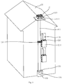
FIG. 2 is a schematic structural diagram of the parcel transport system shown inFIG. 1 , when the parcel transport system interfaces with a ground equipment. -
FIG. 3 is a schematic structural diagram of the parcel transport system shown inFIG. 1 , when a carrying mechanism of a transport assembly and a storage assembly in the parcel transport system are in a parcel transfer state. -
FIG. 4 is an enlarged view of a part I inFIG. 2 . -
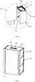
FIG. 5 is a schematic structural diagram of the storage assembly in the parcel transport system shown inFIG. 1 from another angle without a shielding door . -
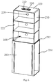
FIG. 6 is a schematic structural diagram of the storage assembly shown inFIG. 5 when the storage assembly is in another state. -
FIG. 7 is a schematic structural diagram of the parcel transport system shown inFIG. 1 , when the parcel transport system is in another state. -
FIG. 8 is a schematic structural diagram of the carrying mechanism of the transport assembly in the parcel transport system shown inFIG. 7 . -
FIG. 9 is a schematic structural diagram of the carrying mechanism shown inFIG. 8 , when the carrying mechanism is in another state. -
FIG. 10 is a schematic structural diagram showing that the carrying mechanism of the transport assembly in the parcel transport system shown inFIG. 1 transfers the parcel to/from the unmanned aerial vehicle landed on a landing platform. -
FIG. 11 is a local schematic diagram of a sliding rail of the transport assembly in the parcel transport system shown inFIG. 3 . - In order to help understanding of the present disclosure, the present disclosure will be described more comprehensively hereinafter with reference to the relevant accompanying drawings.
- As shown in
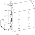
FIG. 1 andFIG. 2 , aparcel transport system 10 according to an implementation is capable of being installed on abuilding 20, which is particularly suitable to be installed on a multi-storey building for storage and delivery of aparcel 30. Theparcel transport system 10 is capable of delivering theparcel 30 between an external equipment (an unmannedaerial vehicle 40, aground equipment 50 such as an unmanned ground vehicle and/or the like) and a user staying in thebuilding 20. Moreover, theparcel transport system 10 is capable of delivering theparcel 30 among the unmannedaerial vehicle 40, the user staying in thebuilding 20 and theground equipment 50, that is, theparcel transport system 10 is used as follows: the unmannedaerial vehicle 40 unloads theparcel 30 onto theparcel transport system 10, the user takes theparcel 30 while staying in thebuilding 20 or theground equipment 50 takes theparcel 30 away; alternatively, the user places theparcel 30 onto theparcel transport system 10 while staying in thebuilding 20, the unmannedaerial vehicle 40 takes theparcel 30 away or theground equipment 50 takes theparcel 30 away; alternatively, theground equipment 50 transfers theparcel 30 to theparcel transport system 10, the unmannedaerial vehicle 40 takes theparcel 30 away or the user takes theparcel 30 while staying in thebuilding 20. - The
parcel transport system 10 comprises an interface assembly, astorage assembly 200 and atransport assembly 400. - Referring to
FIG. 3 , the interface assembly is used for a transfer of theparcel 30 to/from the external equipment. The external equipment may be the unmannedaerial vehicle 40, theground equipment 50, etc. Wherein the ground equipment may be the unmanned ground vehicle and/or the like. Specifically, in the illustrated embodiment, the interface assembly comprises alanding platform 110 and aground facility 120. - The
landing platform 110 is used for landing of the unmannedaerial vehicle 40. A transfer opening 112 for theparcel 30 to pass through is formed in thelanding platform 110. In the illustrated embodiment, thelanding platform 110 is installed on top portion of thebuilding 20, for example, installed on a roof. Thelanding platform 110 is substantially a plate-like structure, thetransfer opening 112 is disposed in central portion of thelanding platform 110, and thelanding platform 110 is horizontally arranged. - It should be understood that the
landing platform 110 is not limited to the above-mentioned structure. Thelanding platform 110 is provided with a workingsurface 114 for the unmannedaerial vehicle 40 to land on, the workingsurface 114 is horizontally arranged, and thetransfer opening 112 is disposed in central portion of the workingsurface 114, thus thelanding platform 110 may take any of a variety of structures. - The
interface facility 120 is capable of carrying out theparcel 30 transfer to/from theground equipment 50. Specifically, theinterface facility 120 is below thelanding platform 110. In the illustrated embodiment, theinterface facility 120 is installed on bottom portion of thebuilding 20. - Referring to
FIG. 4 , a transport opening 122 and aninterface opening 124 are formed in theinterface facility 120. The interface opening 124 is capable of interfacing with theground equipment 50, in order for theparcel 30 transfer between theinterface facility 120 and theground equipment 50. Thetransport opening 122 is used for interfacing with thetransport assembly 400 in order for theparcel 30 transfer. The transport opening 122 and the interface opening 124 are each arranged with adoors 126 respectively. - It should be noted that in order to ease the
parcel 30 transfer between theinterface facility 120 and theground equipment 50, a transfer member (not shown in the figure) used for transferring the parcel is arranged in theinterface facility 120, the transfer member is capable of moving out via the interface opening 124 to receive theparcel 30 from theground equipment 50, or to transfer theparcel 30 to theground equipment 50. Alternatively, theinterface facility 120 may be provided without the transfer member, and theground equipment 50 may be provided with a transfer member. It should be understood that theinterface facility 120 is not limited to the above-mentioned structure, in other embodiments, theinterface facility 120 may be a platform, which enables theparcel 30 to be placed on. - The
storage assembly 200 is capable of being mounted on an exterior wall of thebuilding 20. Specifically, thestorage assembly 200 is arranged adjacent to a communicatingportion 21 of thebuilding 20, wherein the communicatingportion 21 of thebuilding 20 may be a window or a balcony. In the illustrated embodiment, thestorage assembly 200 is arranged adjacent to the window, and thestorage assembly 200 is also positioned between thelanding platform 110 and theinterface facility 120. In other embodiments, thestorage assembly 200 may be arranged in the vicinity of a balcony railing. A plurality ofstorage assemblies 200 are provided, and the plurality ofstorage assemblies 200 are respectively arranged adjacent to a plurality of communicatingportions 21 of thebuilding 20. The number of thestorage assemblies 200 may be configured according to the number of the communicatingportions 21 which thebuilding 20 has, and may be configured as needed. - Referring to
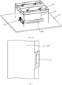
FIG. 5 , in the illustrated embodiment, eachstorage assembly 200 comprises anouter box body 210 and astorage box 220. - Referring to
FIG. 6 , theouter box body 210 is capable of being mounted on the exterior wall of thebuilding 20. Theouter box body 210 is installed below the communicatingportion 21 of thebuilding 20. Afirst opening 212 and asecond opening 214 are formed in theouter box body 210. In one embodiment, theouter box body 210 is substantially cuboid-shaped, thefirst opening 212 and thesecond opening 214 are respectively arranged in two adjacent faces of theouter box body 210. In the illustrated embodiment, theouter box body 210 is provided with a bottom wall opposite to thefirst opening 212, the bottom wall is configured to face downwards, thefirst opening 212 is configured to face upwards. - It should be understood that the
outer box body 210 is not limited to the above-mentioned structure, and theouter box body 210 may be configured as needed. - The
storage box 220 is used for accommodating theparcel 30, wherein thestorage box 220 is provided with a first access opening 222 and a second access opening 224. Thestorage box 220 is movable to enable the first access opening 222 to be exposed and to be blocked. The first access opening 222 is used for the user to take or put theparcel 30, and the second access opening 224 is used for a transfer of theparcel 30 between thestorage box 220 and thetransport assembly 400. Specifically, thestorage box 220 is capable of being accommodated in theouter box body 210, enabling theouter box body 210 to block the first access opening 222, thereby preventing the user from putting theparcel 30 into thestorage box 220 and from taking theparcel 30 out of thestorage box 220 via the first access opening 222. Thestorage box 220 is also capable of moving out via thefirst opening 212, enabling the first access opening 222 to be exposed, thereby enabling the user to put theparcel 30 into thestorage box 220 and to take theparcel 30 out of thestorage box 220. When thestorage box 220 is accommodated in theouter box body 210, a position of the second access opening 224 is configured to correspond to a position of thesecond opening 214. Referring toFIG. 7 , in the illustrated embodiment, thestorage box 220 is capable of moving up and down relative to theouter box body 210, and the first access opening 222 is arranged towards thebuilding 20, when the first access opening 222 is exposed, the first access opening 222 is right opposite the communicatingportion 21 of thebuilding 20, facilitating the user to take theparcel 30 out of thestorage box 220 or to put theparcel 30 into thestorage box 220. - In the illustrated embodiment, the
storage box 220 is provided with a plurality ofcompartments 226, eachcompartment 226 is provided with the first access opening 222 and the second access opening 224, positions of the plurality ofsecond access openings 224 are all configured to correspond to a position of thesecond opening 214, and thestorage box 220 is capable of moving out via thefirst opening 212 to make the first access opening 222 of at least part of thecompartments 226 exposed, the user may adjust the number of thefirst access openings 222 which are exposed according to the number ofcompartments 226 which the user needs. It should be understood that the number of thecompartments 226 in thestorage box 220 may be one, the number of thecompartments 226 in thestorage box 220 may be configured as needed, it is more convenient to store a plurality ofparcels 30 at once with the plurality ofcompartments 226. - Further, each
compartment 226 is provided with asensor 228 that is configured to detect the presence of theparcel 30 in therespective compartment 226. Thesensor 228 is a nfc reader or a camera, correspondingly, theparcel 30 is provided with a nfc label or a QR code label respectively. Furthermore, a weight sensor (not shown in the figure) is provided at bottom of thestorage box 220 and is configured to weigh theparcel 30 in thestorage box 220. After each time the user places theparcel 30, a weight gain is measured by the weight sensor, in order to get a weight of theparcel 30. - It should be noted that, when a plurality of the
storage boxes 220 are provided, in order to ensure security of theparcel 30 stored in thestorage box 220, each first access opening 222 may be arranged with an automatic door to prevent one of the users from taking theparcel 30 which belongs to other user. - In the illustrated embodiment, the
storage assembly 200 further comprises a shieldingdoor 230 capable of covering the second access opening 224. The number of the shieldingdoors 230 is consistent with the number of thesecond access openings 224. It should be understood that in other embodiments, the number of the shieldingdoors 230 may be one, and oneshielding door 230 is capable of covering a plurality ofsecond access openings 224. - The
storage assembly 200 further comprises arange sensor 240 mounted to thestorage box 220, therange sensor 240 is capable of detecting an obstacle in order for movement control of thestorage box 220, so as to prevent thestorage box 220 from colliding with an obstacle (e.g. an opened casement) in a direction of movement. - The
storage assembly 200 further comprises analarm 250 mounted to thestorage box 220, the alarm is capable of giving an alarm while thestorage box 220 is moving, so as to remind the user. Specifically, thealarm 250 is an alarm lamp, a sound alerter, and/or the like. - The
transport assembly 400 is capable of transporting theparcel 30. Thetransport assembly 400 is capable of reaching into thestorage box 220 via the second access opening 224, enabling thetransport assembly 400 to move theparcel 30 into or out of thestorage box 220. Thetransport assembly 400 is capable of moving theparcel 30 into or out of thestorage box 220, thetransport assembly 400 is capable of carrying out theparcel 30 transfer to/from the interface assembly at the interface assembly, so that thetransport assembly 400 is capable of delivering theparcel 30 between the interface assembly and thestorage box 220. Thetransport assembly 400 is capable of transferring theparcel 30 to/from the unmannedaerial vehicle 40 at thelanding platform 110, and thetransport assembly 400 is also capable of transferring theparcel 30 to/from theinterface facility 120, enabling thetransport assembly 400 to deliver theparcel 30 among thelanding platform 110, thestorage box 220 and theinterface facility 120. Specifically, when thestorage box 220 is accommodated in theouter box body 210, thetransport assembly 400 is capable of reaching into thestorage box 220 via the second access opening 224 and thesecond opening 214. The shieldingdoor 230 which covers the second access opening 224 is capable of being opened automatically when theparcel 30 is transferred between thetransport assembly 400 and thestorage box 220, and the shieldingdoor 230 is in a closed state when there is noparcel 30 transfer. - In the illustrated embodiment, the
transport assembly 400 comprises a slidingrail 410 and acarrying mechanism 420 capable of sliding along the slidingrail 410 and carrying theparcel 30. - One end of the sliding
rail 410 extends to thetransfer opening 112, and the other end of the slidingrail 410 extends to theinterface facility 120. Specifically, one end of the slidingrail 410 is far away from thetransfer opening 112, and extends to thetransport opening 122 of theinterface facility 120. In the illustrated embodiment, the slidingrail 410 extends in vertical direction. Thestorage box 220 is arranged proximate the slidingrail 410. Specifically, the second access opening 224 is arranged towards the slidingrail 410. - The carrying
mechanism 420 is capable of being positioned at the transfer opening 112 to carry out theparcel 30 transfer to/from the unmannedaerial vehicle 40, and thecarrying mechanism 420 is capable of being positioned at theinterface facility 120 to carry out theparcel 30 transfer to/from theinterface facility 120, and thecarrying mechanism 420 is also capable of reaching into thestorage box 220 via the second access opening 224, enabling thecarrying mechanism 420 to deliver theparcel 30 among thetransfer opening 112, thestorage box 220 and theinterface facility 120. Specifically, the carryingmechanism 420 is capable of being positioned at thetransport opening 122, in order to carry out theparcel 30 transfer to/from theinterface facility 120 via thetransport opening 122. - Referring to
FIG. 8 and FIG. 9 , in the illustrated embodiment, the carryingmechanism 420 comprises a slidingcarriage 422, clampingarms 424 and atransmission device 426. - The sliding
carriage 422 is capable of sliding along the slidingrail 410. A throughhole 422a for theparcel 30 to pass through is formed in the slidingcarriage 422. In one embodiment, the slidingcarriage 422 is roughly a U-shaped structure, and the slidingcarriage 422 includes abottom plate 422b and two opposite supportingplates 422c fixedly connected with thebottom plate 422b. Thebottom plate 422b is perpendicular to the direction in which the slidingrail 410 extends, and the two supportingplates 422c extend in vertical direction away from thebottom plate 422b. The throughhole 422a is formed in thebottom plate 422b. Specifically, an exterior side of one of thesupport plates 422c is slidably connected with the slidingrail 410. - The two clamping
arms 424 are both installed on the slidingcarriage 422, so that the two clampingarms 424 are capable of sliding along the slidingrail 410 with the slidingcarriage 422. The two clampingarms 424 are oppositely arranged. At least one of the two clampingarms 424 is capable of sliding in a first direction, so that a distance between the two clampingarms 424 is adjustable, enabling the two clampingarms 424 to clamp theparcel 30 and to release theparcel 30. The two clampingarms 424 are also capable of extending or retracting in a second direction perpendicular to the first direction, and the two clampingarms 424 are capable of reaching into thestorage box 220 via the second access opening 224, enabling the two clampingarms 424 to move theparcel 30 into or out of thestorage box 220. The two clampingarms 424 are capable of passing through thetransfer opening 112 when being in a retracted state, in order for theparcel 30 transfer to/from the unmannedaerial vehicle 40, as shown inFIG. 10 . - In the illustrated embodiment, the first direction and the second direction are both perpendicular to the direction in which the sliding
rail 410 extends. - A clamped space is formed between the two clamping
arms 424. When the two clampingarms 424 are in the retracted state, the clamped space is configured to correspond to a position of the throughhole 422a. As shown inFIG. 4 , when thecarrying mechanism 420 is positioned at thetransport opening 122 of theinterface facility 120, the throughhole 422a is right opposite thetransport opening 122, enabling theparcel 30 to pass through the throughhole 422a and thetransport opening 122, in order for theparcel 30 transfer between the two clampingarms 424 and theinterface facility 120. - Specifically, each clamping
arm 424 comprises a mountingplate 424a and aclamping plate 424b mounted on the mountingplate 424a. The mountingplates 424a of the two clampingarms 424 are oppositely arranged, and at least one of the mountingplates 424a of the two clampingarms 424 is capable of sliding in the first direction, so that a distance between the clamping plates 404b of the two clampingarms 424 is adjustable to enable the clamping plates 404b to clamp theparcel 30 and to release theparcel 30. The clampingplates 424b are capable of sliding in the second direction, enabling the clampingplates 424b to reach into thestorage box 220 via the second access opening 224, in order to move theparcel 30 into or out of thestorage box 220. In the illustrated embodiment, the mountingplates 424a of the two clampingarms 424 are both parallel to the two supportingplates 422c of the slidingcarriage 422, the clamping plates 424B are each disposed on the opposite sides of the fixing plates 424A of the two clampingarms 424 respectively. - Moreover, each clamping
arm 424 further comprises apositioning piece 424c mounted to theclamping plate 424b, the positioningpieces 424c are each disposed on the opposite sides of the clampingplates 424b of the two clampingarms 424 respectively, and are each disposed at end portion of therespective clamping plate 424b in the second direction. The positioningpieces 424c are capable of being driven by sliding of the clampingplates 424b in the second direction, to push theparcel 30 located in thestorage box 220, so as to adjust a position of theparcel 30, enabling theparcel 30 to be placed properly relative to the clampingplates 424b in the second direction when the clampingplates 424b clamp theparcel 30. Specifically, each clampingplate 424b is provided with two positioningpieces 424c, and each of the twopositioning pieces 424c is respectively disposed at each end of therespective clamping plate 424b in the second direction, thus thestorage assemblies 200 may be installed at both two sides of the slidingrail 410. It should be understood that in other embodiments, each clampingplate 424b is provided with onepositioning piece 424c, and thepositioning piece 424c of each clampingplate 424b is disposed at single end of therespective clamping plate 424b in the second direction, thus it is suitable to install thestorage assemblies 200 at single side of the slidingrail 410, and thepositioning piece 424c of the two clampingplates 424b are disposed close to thestorage assembly 200. - Further, the clamping
plate 424b has a supportingportion 424d perpendicular to a plate surface of theclamping plate 424b, the supportingportions 424d are each disposed on the opposite sides of clampingplates 424b of the two clampingarms 424 respectively, and are capable of jointly supporting theparcel 30. Specifically, the supportingportion 424d extends in the second direction from one end to the other end of theclamping plate 424b. With the supportingportions 424d arranged, the carryingmechanism 420 is capable of carrying theparcel 30 not only by clamping theparcel 30, but also by supporting theparcel 30 via the supportingportions 424d. - Referring to
FIG. 11 , specifically, the slidingrail 410 is provided with anelectrical interface 412 capable of being electrically connected to thestorage assembly 200 with a cable, so that the slidingrail 410 is capable of supplying electricity to thestorage assembly 200 and transmitting data to/from thestorage assembly 200. - The
transmission device 426 is arranged on the slidingcarriage 422, and thetransmission device 426 is capable of driving at least one of the two clampingarms 424 to slide in the first direction. In the illustrated embodiment, thetransmission device 426 is capable of driving the two clampingarms 424 to slide in the opposite directions both parallel to the first direction. Specifically, thetransmission device 426 comprises alead screw 426a, a motor (not shown in the figure), afirst slider 426c and asecond slider 426d. - The
lead screw 426a is capable of being rotatably arranged on the slidingcarriage 422, and thelead screw 426a extends in the first direction. Specifically, thelead screw 426a is provided with both left-hand threads and right-hand threads. Each end of thelead screw 426a rotatably crosses each supportingplate 422c respectively. - The motor and the
lead screw 426a are connected in a transmission way, and the motor is used to drive thelead screw 426a to rotate. - The
first slider 426c and thesecond slider 426d are both sleeved on thelead screw 426a, and are mated with the threads of thelead screw 426a. Thefirst slider 426c and thesecond slider 426d slide in the opposite directions, wherein oneclamping arm 424 is fixedly connected with thefirst slider 426c and theother clamping arm 424 is fixedly connected with thesecond slider 426d, so that oneclamping arm 424 can slide with thefirst slider 426c and theother clamping arm 424 can slide with thesecond slider 426d, so as to make the distance between the two clampingarms 424 adjustable. In the illustrated embodiment, the mountingplate 424a of oneclamping arm 424 is fixedly connected with thefirst slider 426c, and the mountingplate 424a of theother clamping arm 424 is fixedly connected with thesecond slider 426d. - The
transmission device 426 further comprises a guidingrod 426e mounted to the slidingcarriage 422, the guidingrod 426e and thelead screw 426a extend in parallel direction, thefirst slider 426c and thesecond slider 426d are both slidably sleeved on thelead screw 426a. Specifically, each end of the guidingrod 426e is fixedly connected with each supportingplate 422c respectively. - In the illustrated embodiment, two
transmission devices 426 are provided, and eachtransmission device 426 is arranged proximate each end of the bottom plate 422B in the second direction respectively, so as to avoid obstructing theparcel 30 from passing through the throughhole 422a. The lead screws 426a of the twotransmission devices 426 are spaced and parallel, the mountingplate 424a of oneclamping arm 424 is fixedly connected with thefirst sliders 426c of both twotransmission devices 426, and the two mountingplate 424a of theother clamping arm 424 is fixedly connected with thesecond sliders 426d of both twotransmission devices 426. - Further, a protective structure (not shown in the figure) is provided at one side of the sliding rail. The protective structure extends from one end of the sliding
rail 410 to the other end of the slidingrail 410, and links thetransfer opening 112, thetransport opening 122 and thesecond opening 214. When the two clampingarms 424 are in the retracted state, the carryingmechanism 420 is accommodated in the protective structure, so as to protect thecarrying mechanism 420 and theparcel 30 carried by the carryingmechanism 420 from external environment influence. - It should be noted that a control unit is provided to realize intelligent control of the
storage assembly 200, theinterface facility 120 and thetransport assembly 400. Thestorage assembly 200 may be provided without including theouter box body 210, thus the first access opening 222 is configured to face thebuilding 20 and is capable of being blocked by thebuilding 20, thestorage box 220 is capable of moving until the first access opening 222 is right opposite the communicatingportion 21 of thebuilding 20, to make the first access opening 222 exposed, thus thetransport assembly 400 is capable of reaching into thestorage box 220 via the second access opening 224 to move theparcel 30 into or out of thestorage box 220. - It should be understood that the two clamping
arms 424 are not limited to being both slidable in the first direction. In other embodiments, oneclamping arm 424 is able to slide in the first direction, and theother clamping arm 424 is unable to slide in the first direction, correspondingly, thetransmission device 426 includes one slider, and the slider is fixedly connected with theclamping arm 424 which is slidable. - It should be understood that the
transmission device 426 is not limited to the above-mentioned structure. For example, thetransmission device 426 is a telescopic rod, each end of the telescopic rod is fixedly connected with the clamping plate 424B of each clampingarm 424 respectively, the distance between the two clampingarms 424 is adjustable by extension or contraction of thetransmission device 426; alternatively, the slidingcarriage 422 may be omitted, in other embodiments, one of the two clampingarms 424 is arranged on the slidingrail 410, and the other is capable of sliding in the first direction, thetransmission device 426 is a telescopic rod, and each end of the telescopic rod is fixedly connected with the clamping plate 424B of each clampingarms 424 respectively, the distance between the two clampingarms 424 is adjustable by extension or contraction of thetransmission device 426. - The
parcel transport system 10 owns at least advantages listed below. - The
parcel transport system 10 comprises the interface assembly, thestorage assembly 200 and thetransport assembly 400, thestorage assembly 200 comprises thestorage box 220 used for accommodating theparcel 30, and theinterface assembly 200 is capable of theparcel 30 transfer to/from an external equipment, thetransport assembly 400 is capable of reaching into thestorage box 220 via the second access opening 224 to move theparcel 30 into or out of thestorage box 220, thetransport assembly 400 is also capable of carrying out theparcel 30 transfer to/fromground facility 120 at the interface assembly, enabling thetransport assembly 400 to deliver theparcel 30 between the interface assembly and thestorage box 220, thereby realizing and facilitating theparcel 30 delivery between the external equipment and the user. When theparcel transport system 10 is applied to the multi-storey building, the interface assembly is configured depending on the external equipment which the interface assembly needs to interface with, in order to ease theparcel 30 transfer to/from the external equipment; thestorage assembly 200 is installed adjacent to the window of thebuilding 20 or is installed on exterior side of the balcony railing, facilitating the user to receive or send theparcel 30; thestorage box 220 is movable, and makes the first access opening 222 exposed or blocked by movement of thestorage box 220, so as to avoid obstructing a view from the window or from the balcony when thestorage box 220 is not utilized. Thus, theparcel transport system 10 realizes and facilitates theparcel 30 delivery between the user staying in the multi-storey building and the external equipment without a need for the user to go downstairs, and is particularly suitable for theparcel 30 delivery of the multi-storey building. - In addition, the whole or most of components in the
parcel transport system 10 may be installed on exterior of thebuilding 20, dispensing with a lot of work to retrofit interior structure of the existingbuilding 20, thereby lowering both construction difficulty and cost of deploying theparcel transport system 10. - Further, the interface assembly comprises the
landing platform 110 and theinterface facility 120, thelanding platform 110 is used for landing of the unmannedaerial vehicle 40, theinterface facility 120 is capable of carrying out theparcel 30 transfers to/from theground equipment 50, thetransport assembly 400 is capable of being positioned at thetransfer opening 112, in order to transfer theparcel 30 to/from the unmannedaerial vehicle 40, and thetransport assembly 400 is also capable of transferring theparcel 30 to/from theinterface facility 120, thus enabling thetransport assembly 400 to deliver theparcel 30 among thelanding platform 110, thestorage box 220 and theinterface facility 120, thereby realizing and facilitating theparcel 30 delivery among the user, theground equipment 50 and the unmannedaerial vehicle 40. When theparcel transport system 10 is applied to the multi-storey building, thelanding platform 110 may be installed on top portion of thebuilding 20, so as to ease landing of the unmannedaerial vehicle 40 and to keep the unmannedaerial vehicle 40 away from the user, theinterface facility 120 may be arranged on bottom portion of thebuilding 20 to interface with theground equipment 50, thus realizing theparcel 30 delivery among the user staying in the multi-storey building, theground equipment 50 and the unmannedaerial vehicle 40, and it is convenient for the user to receive or send theparcel 30 without the need to go downstairs. - Furthermore, the
storage box 220 is provided with the first access opening 222 and the second access opening 224, the second access opening 224 is used for thetransport assembly 400 to reach into thestorage box 220 so as to move theparcel 30 into or out of thestorage box 220, the first access opening 222 is used for the user to receive or send theparcel 30, thereby making the access opening for the user and the access opening for thetransport assembly 400 separate, ensuring safety of the user. - A method for installing the
parcel transport system 10 according to an implementation, as one of methods for installing theparcel transport system 10, comprising the following steps. - In step S61, installing the interface assembly on the
building 20. - Specifically, the step of installing the interface assembly on the
building 20 includes installing thelanding platform 110 on top portion of thebuilding 20, and installing theinterface facility 120 on bottom portion of thebuilding 20. - More specifically, when installing the
landing platform 110 on top portion of thebuilding 20, the workingsurface 114 of thelanding platform 110 for the unmannedaerial vehicle 40 to land on is horizontally arranged. When installing theinterface facility 120 on bottom portion of thebuilding 20, thetransport opening 122 of theinterface facility 120 is configured to face upwards, and theinterface opening 124 is configured to be positioned in the other side of theinterface facility 120 relative to thebuilding 20. - In step S62, installing the
storage assembly 200 adjacent to the communicatingportion 21 of thebuilding 20, wherein the communicatingportion 21 communicates inside and outside of thebuilding 20, the first access opening 222 of thestorage box 220 is arranged towards thebuilding 20, so that thestorage box 220 is capable of moving until thestorage box 220 is right opposite the communicatingportion 21 and the first access opening 222 is exposed. - Wherein the communicating
portion 21 is the window or the balcony. If the communicatingportion 21 is the window, thestorage assembly 200 is installed below the window; and if the communicatingportion 21 is the balcony, thestorage assembly 200 is installed on exterior side of the balcony railing. - In the illustrated embodiment, the communicating
portion 21 is the window. The bottom wall of theouter box body 210 is opposite to thefirst opening 212, and is configured to face downwards, thefirst opening 212 is configured to face upwards. It should be understood that thestorage assembly 200 is not limited to be installed in the above-mentioned way, in other embodiments, thefirst opening 212 of theouter box body 210 may be configured to face downwards and the bottom wall may be configured to face upwards, while thestorage assembly 200 is installed above the communicatingportion 21. - In step S63, installing the
transport assembly 400 on thebuilding 20. - Specifically, the step of installing the
transport assembly 400 on thebuilding 20 includes installing the slidingrail 410 extending in the first direction on thebuilding 20, making one end of the slidingrail 410 extend to thetransfer opening 112 and making the other end of the slidingrail 410 extend to theinterface facility 120, wherein thecarrying mechanism 420 is installed on the slidingrail 410, and thecarrying mechanism 420 comprises two clampingarms 424, which are oppositely arranged, at least one of the two clampingarms 424 is capable of sliding in the first direction, the two clampingarms 424 are also capable of extending or retracting in the second direction perpendicular to the first direction. The second access opening 224 of thestorage box 220 is arranged towards the slidingrail 410, enabling the two clampingarms 424 to reach into thestorage box 220 via the second access opening 224. - More specifically, one end of the sliding
rail 410 is far away from thetransfer opening 112, and extends to thetransport opening 122 of theinterface facility 120. - It should be understood that the above-mentioned method for installing the
parcel transport system 10 is not limited to following the above-mentioned sequence. The sequence of the steps S61, S62 and S63 may be changed freely, for example, thetransport assembly 400 may be installed first, the interface assembly and thestorage assembly 200 may be installed afterwards, and so on. - As the
parcel transport system 10 is installed by the above-mentioned method, not only is physical contact of the user and the unmannedaerial vehicle 40 avoided, ensuring safety of the user, but also the user does not need to go downstairs for receiving or sending theparcel 30, making life easier. - A method for delivering the
parcel 30 according to an implementation, as one of methods for delivering theparcel 30 based on theparcel transport system 10, comprising the following steps. - In step S71, the unmanned
aerial vehicle 40 lands on thelanding platform 110, and unloads theparcel 30 onto thetransport assembly 400 positioned at thelanding platform 110. - Specifically, the step that the unmanned
aerial vehicle 40 unloads theparcel 30 onto thetransport assembly 400 positioned at thelanding platform 110 is as follows: the two clampingarms 424 of thetransport assembly 400 pass through thetransfer opening 112, the unmannedaerial vehicle 40 places theparcel 30 between the two clampingarms 424, the two clampingarms 424 slide in the first direction to make closer to each other, so as to clamp theparcel 30, then the unmannedaerial vehicle 40 unloads theparcel 30. - In step S72, the
transport assembly 400 reaches into thestorage box 220 via the second access opening 224, so as to move theparcel 30 into thestorage box 220, in order for the user to take theparcel 30 via the first access opening 222, alternatively, thetransport assembly 400 delivers theparcel 30 to theinterface facility 120, in order for theground equipment 50 to take theparcel 30 away. - Thus, after the
transport assembly 400 takes theparcel 30, there are two ways for thetransport assembly 400 to deliver theparcel 30, one way is that thetransport assembly 400 reaches into thestorage box 220 via the second access opening 224 to move theparcel 30 into thestorage box 220, the other way is that thetransport assembly 400 delivers theparcel 30 to theinterface facility 120. - Specifically, the step that the
transport assembly 400 reaches into thestorage box 220 via the second access opening 224 to move theparcel 30 into thestorage box 220 is as follows: the carryingmechanism 420 slides along the slidingrail 410 to approach thestorage box 220, the two clampingarms 424 both extend and reach into thestorage box 220 via the second access opening 224, so as to move theparcel 30 into thestorage box 220; the two clampingarms 424 slide to make farther from each other, thereby releasing theparcel 30, then the two clampingarms 424 both retract to leave thestorage box 220. In this way, after the step that thetransport assembly 400 reaches into thestorage box 220 via the second access opening 224 to move theparcel 30 into thestorage box 220, thestorage box 220 moves out of theouter box body 210 via thefirst opening 212, to make the first access opening 222 right opposite the communicatingportion 21, the user takes theparcel 30 out of thestorage box 220 via the first access opening 222; subsequently, thestorage box 220 moves back into theouter box body 210 to make the first access opening 222 blocked by theouter box body 210. - Specifically, the step that the
transport assembly 400 delivers theparcel 30 to theinterface facility 120 is as follows: thetransport assembly 400 slides along the slidingrail 410 until it reaches thetransport opening 122 of the interface assembly, the two clampingarms 424 slide in the first direction to make farther from each other so as to release theparcel 30, and theparcel 30 enters theinterface facility 120 through the throughhole 422a and thetransport opening 122. In this way, after the step that thetransport assembly 400 delivers theparcel 30 to theinterface facility 120, there is a step of theparcel 30 transfer between theinterface facility 120 and theground equipment 50 via theinterface opening 124. - This method for delivering the
parcel 30 is based on theparcel transport system 10, realizing that theparcel 30 is automatically delivered from the unmannedaerial vehicle 40 to thestorage box 220 in order for the user staying in thebuilding 20 to take, and to theinterface facility 120 in order for theground equipment 50 to take away. - A method for delivering the
parcel 30 according to another implementation, as one of methods for delivering theparcel 30 based on theparcel transport system 10, comprising the following steps. - In step S81, the
storage box 220 moves to make the first access opening 222 exposed, the user puts theparcel 30 into thestorage box 220, then thestorage box 220 moves again to make the first access opening 222 blocked. - Specifically, step S81 is as follows: the
storage box 220 moves out of theouter box body 210 via thefirst opening 212, to make the first access opening 222 right opposite the communicatingportion 21, the user puts theparcel 30 into thestorage box 220 via the first access opening 222; then thestorage box 220 moves back into theouter box body 210, to make the first access opening 222 blocked by theouter box body 210. - In step S82, the
transport assembly 400 reaches into thestorage box 220 via the second access opening 224, and takes theparcel 30 out. - Specifically, the step S2 is as follows: the carrying
mechanism 420 slides along the slidingrail 410 to approach thestorage box 220; the two clampingarms 424 both extend and reach into thestorage box 220 via the second access opening 224; the two clampingarms 424 slide to make closer to each other so as to clamp theparcel 30, then the two clampingarms 424 both retract to move theparcel 30 out of thestorage box 220. - Further, the step that the two clamping
arms 424 slide to make closer to each other so as to clamp theparcel 30 is as follows: the two clampingarms 424 slide to make closer to each other, until a distance between the positioningpieces 424c of the two clampingarms 424 is less than a width of theparcel 30, the two clampingarms 424 both retract to make thepositioning pieces 424c push theparcel 30 to the specified position, then the two clampingarms 424 extend again, and subsequently slide to make closer to each other so as to clamp theparcel 30. - In step S83, the
transport assembly 400 delivers theparcel 30 to theinterface facility 120, in order for theground equipment 50 to take theparcel 30 away, alternatively, thetransport assembly 400 delivers theparcel 30 to thetransfer opening 112, in order for the unmannedaerial vehicle 40 to take theparcel 30 away. - Thus, after the
transport assembly 400 takes theparcel 30, there are two ways for thetransport assembly 400 to deliver theparcel 30, one way is that thetransport assembly 400 delivers theparcel 30 to theinterface facility 120, the other way is that thetransport assembly 400 delivers theparcel 30 to thetransfer opening 112, in order for the unmannedaerial vehicle 40 to take theparcel 30 away. - Specifically, the step that the
transport assembly 400 delivers theparcel 30 to theinterface facility 120 is as follows: thetransport assembly 400 slides along the slidingrail 410 until it reaches thetransport opening 122 of the interface assembly, the two clampingarms 424 slide in the first direction to make farther from each other so as to release theparcel 30, and theparcel 30 enters theinterface facility 120 through the throughhole 422a and thetransport opening 122. In this way, after the step that thetransport assembly 400 delivers theparcel 30 to theinterface facility 120, there is a step of theparcel 30 transfer between theinterface facility 120 and theground equipment 50 via theinterface opening 124. - Specifically, the step that the
transport assembly 400 delivers theparcel 30 to the transfer opening 112 in order for the unmannedaerial vehicle 40 to take theparcel 30 away is as follows: thetransport assembly 400 slides along the slidingrail 410 with theparcel 30 until the two clampingarms 424 of thetransport assembly 400 pass through thetransfer opening 112. In this way, after the step that thetransport assembly 400 delivers theparcel 30 to thetransfer opening 112, there is a step that the unmannedaerial vehicle 40 secures theparcel 30, and the two clampingarms 424 slide in the first direction to make farther from each other so as to release theparcel 30. - This method for delivering the
parcel 30 is based on theparcel transport system 10, realizing that theparcel 30 is automatically delivered from the user staying in thebuilding 20 to theinterface facility 120 and to the unmannedaerial vehicle 40. - A method for delivering the
parcel 30 according to another implementation, as one of methods for delivering theparcel 30 based on theparcel transport system 10, comprising the following steps. - In step S91, the
ground equipment 50 transfers theparcel 30 to theinterface facility 120. - Specifically, the
ground equipment 50 transfers theparcel 30 to theinterface facility 120 via thetransport opening 122. - In step S92, the
transport assembly 400 takes theparcel 30 from theinterface facility 120. - Specifically, the step that the
transport assembly 400 takes theparcel 30 from theinterface facility 120 is as follows: thetransport assembly 400 slides along the slidingrail 410 until it reaches thetransport opening 122 of the interface assembly, theinterface facility 120 moves theparcel 30 through thetransport opening 122 and the throughhole 422a until theparcel 30 is placed between the two clampingarms 424, then the two clampingarms 424 slide in the first direction to make closer to each other so as to clamp theparcel 30. - In step S93, the
transport assembly 400 reaches into thestorage box 220 via the second access opening 224, so as to move theparcel 30 into thestorage box 220, in order for the user to take theparcel 30 via the first access opening 222, alternatively, thetransport assembly 400 delivers theparcel 30 to thetransfer opening 112, in order for the unmannedaerial vehicle 40 to take theparcel 30 away. - Thus, after the
transport assembly 400 takes theparcel 30, there are two ways for thetransport assembly 400 to deliver theparcel 30, one way is that thetransport assembly 400 reaches into thestorage box 220 via the second access opening 224 to move theparcel 30 into thestorage box 220, the other way is that thetransport assembly 400 delivers theparcel 30 to thetransfer opening 112, in order for the unmannedaerial vehicle 40 to take theparcel 30 away. - Specifically, the step that the
transport assembly 400 reaches into thestorage box 220 via the second access opening 224 to move theparcel 30 into thestorage box 220 is as follows: the carryingmechanism 420 slides along the slidingrail 410 to approach thestorage box 220, the two clampingarms 424 both extend and reach into thestorage box 220 via the second access opening 224, so as to move theparcel 30 into thestorage box 220; the two clampingarms 424 slide to make farther from each other, thereby releasing theparcel 30, then the two clampingarms 424 both retract to leave thestorage box 220. In this way, after the step that thetransport assembly 400 reaches into thestorage box 220 via the second access opening 224 to move theparcel 30 into thestorage box 220, thestorage box 220 moves out of theouter box body 210 via thefirst opening 212, to make the first access opening 222 right opposite the communicatingportion 21, the user takes theparcel 30 out of thestorage box 220 via the first access opening 222; subsequently, thestorage box 220 moves back into theouter box body 210 to make the first access opening 222 blocked by theouter box body 210. - Specifically, the step that the
transport assembly 400 delivers theparcel 30 to the transfer opening 112 in order for the unmannedaerial vehicle 40 to take theparcel 30 away is as follows: thetransport assembly 400 slides along the slidingrail 410 with theparcel 30 until the two clampingarms 424 of thetransport assembly 400 pass through thetransfer opening 112. In this way, after the step that thetransport assembly 400 delivers theparcel 30 to thetransfer opening 112, there is a step that the unmannedaerial vehicle 40 secures theparcel 30, and the two clampingarms 424 slide in the first direction to make farther from each other so as to release theparcel 30. - This method for delivering the
parcel 30 is based on theparcel transport system 10, realizing that theparcel 30 is automatically delivered from theground equipment 50 to the user staying in thebuilding 20 and to the unmannedaerial vehicle 40. - The technical features of the above-mentioned embodiments can be combined. In order to simplify the description, not all possible combinations of the technical features of the above-mentioned embodiments have been provided. It can be appreciated that, as long as no contradiction is concluded from these combinations, all reasonable combinations of the features should be considered as the scope recorded in the description.
- The present disclosure mainly presents several embodiments with their descriptions more specific and detailed than others, but they should not be construed as limiting the scope of the present disclosure. It should be noted that for persons skilled in the art, several modifications and improvements can be made without departing from the conception of the present disclosure, which shall all fall within the scope of the present disclosure. Therefore, the scope of the present disclosure shall be subject to the appended claims.
Claims (20)
- A parcel transport system, comprising:an interface assembly used for a transfer of a parcel to or from an external equipment;a storage assembly comprising a storage box used for accommodating the parcel, wherein the storage box is provided with a first access opening and a second access opening, and the storage box is movable to enable the first access opening to be exposed and to be blocked; anda transport assembly capable of transporting the parcel,wherein the transport assembly is capable of reaching into the storage box via the second access opening, enabling the transport assembly to move the parcel into or out of the storage box; andwherein the transport assembly is capable of carrying out the parcel transfer to the interface assembly at the interface assembly, or carrying out the parcel transfer from or the interface assembly at the interface assembly, enabling the transport assembly to deliver the parcel between the interface assembly and the storage box.
- The parcel transport system of claim 1, wherein the interface assembly comprises a landing platform and a ground facility, the landing platform is used for landing of an unmanned aerial vehicle, the interface facility is used for the parcel transfer to or from a ground equipment, the transport assembly is capable of carrying out the parcel transfer to or from the unmanned aerial vehicle at the landing platform, and the transport assembly is also capable of carrying out the parcel transfer to or from the interface facility, enabling the transport assembly to deliver the parcel among the landing platform, the storage box and the interface facility.
- The parcel transport system of claim 2, wherein a transfer opening for the parcel to pass through is formed in the landing platform, the transport assembly comprises a sliding rail and a carrying mechanism capable of sliding along the sliding rail and carrying the parcel, one end of the sliding rail extends to the transfer opening, and the other end of the sliding rail extends to the interface facility, so that the carrying mechanism is capable of being positioned at the transfer opening to carry out the parcel transfer to or from the unmanned aerial vehicle, and the carrying mechanism is capable of being positioned at the interface facility; and wherein the storage box is arranged proximate the sliding rail, the carrying mechanism is also capable of reaching into the storage box via the second access opening, enabling the carrying mechanism to deliver the parcel among the transfer opening, the storage box and the interface facility.
- The parcel transport system of claim 3, wherein the second access opening is arranged towards the sliding rail, the carrying mechanism comprises two clamping arms, which are oppositely arranged, at least one of the two clamping arms is capable of sliding in a first direction, so that a distance between the two clamping arms is adjustable to enable the two clamping arms to clamp and to release the parcel, and the two clamping arms are also capable of extending or retracting in a second direction perpendicular to the first direction, so that the two clamping arms are capable of reaching into the storage box via the second access opening; and wherein the two clamping arms are capable of passing through the transfer opening when being in a retracted state, in order for the parcel transfer to or from the unmanned aerial vehicle.
- The parcel transport system of claim 4, wherein each clamping arm comprises a mounting plate and a clamping plate mounted on the mounting plate, the mounting plates of the two clamping arms are oppositely arranged, and at least one of the mounting plates of the two clamping arms is capable of sliding in the first direction, so that a distance between the clamping plates of the two clamping arms is adjustable to enable the clamping plates to clamp and to release the parcel, and the clamping plates are capable of sliding in the second direction, so that the clamping plates are capable of reaching into the storage box via the second access opening.
- The parcel transport system of claim 5, wherein each clamping arm further comprises a positioning piece mounted to the clamping plate, the positioning pieces of the two clamping arms are each disposed on the opposite sides of the clamping plates of the two clamping arms respectively, and are each disposed at end portion of the respective clamping plate in the second direction, the positioning pieces are capable of pushing the parcel located in the storage box to adjust a position of the parcel.
- The parcel transport system of claim 5, wherein the clamping plate has a supporting portion perpendicular to a plate surface of the clamping plate, the supporting portions of the two clamping arms are each disposed on the opposite sides of the clamping plates of the two clamping arms respectively and are capable of jointly supporting the parcel.
- The parcel transport system of claim 4, wherein a transport opening and an interface opening are formed in the interface facility, the interface opening is capable of interfacing with the ground equipment, in order for the parcel transfer between the interface facility and the ground equipment, one end of the sliding rail is far away from the transfer opening and extends to the transport opening of the interface facility, so that the carrying mechanism is capable of being positioned at the transport opening; and wherein the transport assembly further comprises a sliding carriage capable of sliding along the sliding rail, a through hole for the parcel to pass through is formed in the sliding carriage, the two clamping arms are both installed on the sliding carriage, so that the two clamping arms are capable of sliding along the sliding rail with the sliding carriage, a clamped space is formed between the two clamping arms, when the two clamping arms are in the retracted state, the clamped space is configured to correspond to a position of the through hole; and wherein when the carrying mechanism is positioned at the transport opening of the interface facility, the through hole is right opposite the transport opening, enabling the parcel to pass through the through hole and the transport opening, in order for the parcel transfer between the two clamping arms and the interface facility.
- The parcel transport system of any one of claims 4 to 8, wherein the sliding rail extends in vertical direction, the first direction and the second direction are both perpendicular to the direction in which the sliding rail extends, the landing platform is above the interface facility, the landing platform is provided with a working surface for the unmanned aerial vehicle to land on, the working surface is horizontally arranged, and the transfer opening is disposed in central portion of the working surface, the storage assembly is positioned between the landing platform and the interface facility;
additionally or alternatively, wherein the sliding rail is provided with an electrical interface capable of being electrically connected to the storage assembly with a cable, so that the sliding rail is capable of supplying electricity to the storage assembly and transmitting data to or from the storage assembly. - The parcel transport system of any one of claims 1 to 8, wherein the storage assembly further comprises a shielding door capable of covering the second access opening.
- The parcel transport system of any one of claims 1 to 8, wherein the storage assembly further comprises an outer box body, a first opening and a second opening are formed in the outer box body, and the storage box is capable of being accommodated in the outer box body, enabling the outer box body to block the first access opening, and the storage box is also capable of moving out via the first opening, enabling the first access opening to be exposed; and wherein when the storage box is accommodated in the outer box body, a position of the second access opening is configured to correspond to a position of the second opening, and the transport assembly is capable of reaching into the storage box via the second access opening and the second opening.
- The parcel transport system of claim 11, wherein the storage box is provided with a plurality of compartments, each compartment is provided with the first access opening and the second access opening, positions of a plurality of second access openings are all configured to correspond to the position of the second opening, and the storage box is capable of moving out via the first opening to make the first access opening of at least part of the compartments exposed.
- The parcel transport system of claim 12, wherein each compartment is provided with a sensor that is configured to detect the presence of the parcel in the respective compartment, the sensor is a nfc reader or a camera.
- The parcel transport system of any one of claims 1 to 8, wherein the storage assembly further comprises a range sensor mounted to the storage box, the range sensor is capable of detecting an obstacle in order for movement control of the storage box;
additionally or alternatively, wherein the storage assembly further comprises an alarm mounted to the storage box, the alarm is capable of giving an alarm while the storage box is moving. - A method for installing a parcel transport system, comprising:providing the parcel transport system of claim 1;installing the interface assembly on a building;installing the storage assembly adjacent to a communicating portion of the building, wherein the communicating portion communicates inside and outside of the building, the first access opening of the storage box is arranged towards the building, so that the storage box is capable of moving until the storage box is right opposite the communicating portion and the first access opening is exposed; andinstalling the transport assembly on the building.
- The method of claim 15, wherein the communicating portion is a window or a balcony.
- The method of claim 15, wherein the interface assembly comprises a landing platform and a ground facility, the step of installing the interface assembly on the building includes installing the landing platform on top portion of the building and installing the ground facility on bottom portion of the building;
wherein the step of installing the transport assembly on the building includes installing the sliding rail extending in vertical direction on the building, making one end of the sliding rail extend to a transfer opening and making the other end of the sliding rail extend to a transport opening of the ground facility; wherein the carrying mechanism is installed on the sliding rail, and the carrying mechanism comprises two clamping arms, which are oppositely arranged, at least one of the two clamping arms is capable of sliding in a first direction, the two clamping arms are also capable of extending or retracting in a second direction perpendicular to the first direction; and wherein the second access opening of the storage box is arranged towards the sliding rail, enabling the two clamping arms to reach into the storage box via the second access opening. - A method for delivering a parcel, comprising:providing the parcel transport system of claim 2;the unmanned aerial vehicle landing on the landing platform and unloading the parcel onto the transport assembly positioned at the landing platform;the transport assembly reaching into the storage box via the second access opening so as to move the parcel into the storage box, in order for the user to take the parcel via the first access opening, alternatively, the transport assembly delivering the parcel to the ground facility, in order for the ground equipment to take the parcel away.
- A method for delivering a parcel, comprising:providing the parcel transport system of claim 2;the storage box moving to make the first access opening exposed, the user putting the parcel into the storage box, then the storage box moving again to make the first access opening blocked;the transport assembly reaching into the storage box via the second access opening and taking the parcel out;the transport assembly delivering the parcel to the ground facility in order for the ground equipment to take the parcel away, alternatively, the transport assembly delivering the parcel to the transfer opening in order for the unmanned aerial vehicle to take the parcel away.
- A method for delivering a parcel, comprising:providing the parcel transport system of claim 2;the ground equipment transferring the parcel to the ground facility;the transport assembly taking the parcel from the ground facility;the transport assembly reaching into the storage box via the second access opening so as to move the parcel into the storage box, in order for the user to take the parcel via the first access opening, alternatively, the transport assembly delivering the parcel to the transfer opening in order for the unmanned aerial vehicle to take the parcel away.
Applications Claiming Priority (1)
| Application Number | Priority Date | Filing Date | Title |
|---|---|---|---|
| PCT/CN2018/120553 WO2020118552A1 (en) | 2018-12-12 | 2018-12-12 | Product delivery system and installation method thereof, and product delivery method |
Publications (2)
| Publication Number | Publication Date |
|---|---|
| EP3896005A1 true EP3896005A1 (en) | 2021-10-20 |
| EP3896005A4 EP3896005A4 (en) | 2022-06-22 |
Family
ID=71075544
Family Applications (1)
| Application Number | Title | Priority Date | Filing Date |
|---|---|---|---|
| EP18942920.2A Pending EP3896005A4 (en) | 2018-12-12 | 2018-12-12 | Product delivery system and installation method thereof, and product delivery method |
Country Status (5)
| Country | Link |
|---|---|
| US (1) | US20210309363A1 (en) |
| EP (1) | EP3896005A4 (en) |
| JP (1) | JP7389506B2 (en) |
| CN (2) | CN116788773A (en) |
| WO (1) | WO2020118552A1 (en) |
Cited By (1)
| Publication number | Priority date | Publication date | Assignee | Title |
|---|---|---|---|---|
| EP3984919A4 (en) * | 2019-06-14 | 2023-07-12 | Zhou, Pengyue | Goods access terminal and assembly method thereof |
Families Citing this family (6)
| Publication number | Priority date | Publication date | Assignee | Title |
|---|---|---|---|---|
| US11960282B2 (en) * | 2021-01-05 | 2024-04-16 | Abb Schweiz Ag | Systems and methods for servicing a data center using autonomous vehicle |
| US11814170B2 (en) * | 2021-02-04 | 2023-11-14 | Skyway Technologies Corp. | Aircraft package delivery mounting system |
| US11379784B1 (en) | 2021-04-09 | 2022-07-05 | James Lawrence Eastman | Drone delivery systems and methods |
| WO2023154524A1 (en) * | 2022-02-14 | 2023-08-17 | Miller Kenneth C | Robotic receiving and dispersement system |
| US11932417B2 (en) * | 2022-04-14 | 2024-03-19 | Strix Drones Ltd | Autonomous UAV package delivery system |
| US11643275B1 (en) * | 2022-09-01 | 2023-05-09 | Todoo Ltd. | Apparatus for a dispatch and delivery system |
Family Cites Families (26)
| Publication number | Priority date | Publication date | Assignee | Title |
|---|---|---|---|---|
| JP3797069B2 (en) * | 2000-07-28 | 2006-07-12 | 株式会社ダイフク | Goods storage facility |
| JP4007204B2 (en) * | 2003-01-30 | 2007-11-14 | 松下電器産業株式会社 | Robot system |
| US9834378B2 (en) * | 2006-12-22 | 2017-12-05 | Brooks Automation, Inc. | Loader and buffer for reduced lot size |
| WO2014080389A2 (en) * | 2014-03-25 | 2014-05-30 | Alshdaifat, Wasfi | Autonomous ground station interfacing aerial delivery |
| WO2014080390A2 (en) * | 2014-04-01 | 2014-05-30 | Wasfi Alshdaifat | Autonomous conveyor interfacing aerial delivery |
| US9990684B2 (en) * | 2014-05-01 | 2018-06-05 | Sammy Hejazi | Mailport for automated parcel carriers |
| WO2016021916A1 (en) * | 2014-08-05 | 2016-02-11 | 남정우 | Item receiving apparatus |
| DE102014112480A1 (en) * | 2014-08-29 | 2016-03-03 | Josef Weilbuchner | Apparatus for receiving and storing mail and delivery mail and methods of using the apparatus |
| US9758301B2 (en) * | 2015-03-24 | 2017-09-12 | Joseph Porat | System and method for overhead warehousing |
| EP3321179B1 (en) * | 2015-07-06 | 2020-09-09 | Zero Co., Ltd. | Rotorcraft landing device |
| ITUB20155527A1 (en) * | 2015-11-12 | 2017-05-12 | Federico Bruni | METHOD, WAREHOUSE, DRONE AND SHIPMENT SYSTEM |
| US9777502B2 (en) * | 2015-12-18 | 2017-10-03 | Amazon Technologies, Inc. | Multi-level fulfillment center for unmanned aerial vehicles |
| CN205563689U (en) * | 2016-04-25 | 2016-09-07 | 袁家鑫 | End system of self -service receiving and sending parcel |
| JP6567586B2 (en) * | 2017-02-03 | 2019-08-28 | 株式会社Go−One | Locker system and control method thereof |
| CN107140443A (en) * | 2017-05-06 | 2017-09-08 | 佛山市神风航空科技有限公司 | A kind of high-rise building logistics transportation system based on unmanned plane |
| CN206984905U (en) * | 2017-06-16 | 2018-02-09 | 杭州万兴科技股份有限公司 | A kind of roof goods intelligent distribution system |
| CN207226563U (en) * | 2017-08-31 | 2018-04-13 | 周鹏跃 | Unmanned plane cargo receive-transmit system |
| CN207390180U (en) * | 2017-09-30 | 2018-05-22 | 周鹏跃 | Access goods system |
| CN207390181U (en) * | 2017-09-30 | 2018-05-22 | 周鹏跃 | Access goods system |
| CN107720069A (en) * | 2017-10-26 | 2018-02-23 | 安吉智能物联技术有限公司 | Switch cabinet in a kind of intelligent express delivery |
| CN208199499U (en) * | 2017-12-13 | 2018-12-07 | 温州翰轩林工业设计有限公司 | A kind of placement shelf of motorcycle accessories |
| CN108764779A (en) * | 2018-05-02 | 2018-11-06 | 广东容祺智能科技有限公司 | A kind of building express delivery receive-transmit system based on unmanned plane |
| CN108945918B (en) * | 2018-05-31 | 2021-01-19 | 中航电测仪器股份有限公司 | Get delivery express delivery cabinet with unmanned aerial vehicle and unmanned aerial vehicle |
| JP2018193061A (en) * | 2018-08-21 | 2018-12-06 | 株式会社エアロネクスト | Rotary wing aircraft landing gear |
| CN108876264B (en) * | 2018-08-28 | 2024-03-19 | 北京环球之翼航空科技有限责任公司 | Community express logistics storage and intelligent sorting system |
| CN110040259B (en) * | 2019-03-29 | 2024-04-30 | 深圳市铭科迅捷科技有限公司 | Intelligent logistics cabinet |
-
2018
- 2018-12-12 CN CN202310560179.5A patent/CN116788773A/en active Pending
- 2018-12-12 WO PCT/CN2018/120553 patent/WO2020118552A1/en unknown
- 2018-12-12 CN CN201880100271.0A patent/CN113365928B/en active Active
- 2018-12-12 JP JP2021534256A patent/JP7389506B2/en active Active
- 2018-12-12 EP EP18942920.2A patent/EP3896005A4/en active Pending
-
2021
- 2021-06-11 US US17/345,097 patent/US20210309363A1/en active Pending
Cited By (1)
| Publication number | Priority date | Publication date | Assignee | Title |
|---|---|---|---|---|
| EP3984919A4 (en) * | 2019-06-14 | 2023-07-12 | Zhou, Pengyue | Goods access terminal and assembly method thereof |
Also Published As
| Publication number | Publication date |
|---|---|
| CN113365928B (en) | 2023-06-09 |
| EP3896005A4 (en) | 2022-06-22 |
| JP2022522587A (en) | 2022-04-20 |
| US20210309363A1 (en) | 2021-10-07 |
| WO2020118552A1 (en) | 2020-06-18 |
| CN116788773A (en) | 2023-09-22 |
| JP7389506B2 (en) | 2023-11-30 |
| CN113365928A (en) | 2021-09-07 |
Similar Documents
| Publication | Publication Date | Title |
|---|---|---|
| EP3896005A1 (en) | Product delivery system and installation method thereof, and product delivery method | |
| CN107697304B (en) | Goods receiving and dispatching system for unmanned aerial vehicle and goods receiving and sending method | |
| EP3107842B1 (en) | System for storing products, method for using such a system as well as a central control unit arranged to be operative in such a system | |
| US10676284B2 (en) | Window-based delivery apparatus for packages conveyed by drones | |
| US20180295327A1 (en) | Surveillance unit | |
| WO2016163779A1 (en) | Drone-delivery receiving box | |
| WO2015026018A1 (en) | Apparatus for charging and housing unmanned vertical takeoff and landing aircraft and method for same | |
| NO20171874A1 (en) | Automated storage and retrieval system and a method of operating the same. | |
| JP2019023020A (en) | Package receiving facility | |
| KR102127682B1 (en) | Dron station with top mounted battery replacement structure | |
| WO2018169218A1 (en) | Cargo loading system | |
| US11951856B2 (en) | Roof structure | |
| JPWO2020136742A1 (en) | Consignment storage device and consignment storage method | |
| JP2020051176A (en) | Cargo receiving structure of building | |
| AU2020261974A1 (en) | Apparatus and method for the maintenance of an overhead line system of a track | |
| US11477912B2 (en) | External robotic system for liquid immersion cooling platform | |
| KR20200111874A (en) | Cargo Loading Port For Cargo Transporting Drone | |
| WO2017164529A1 (en) | Container search system | |
| CN111115246A (en) | Robot sample storage cabinet system | |
| CN101329285A (en) | Vehicle mounted checking system of cobalt-60 container | |
| JPWO2019155854A1 (en) | Multicopter system and baggage delivery method | |
| KR100877749B1 (en) | Vehicle cargo serching system and control method thereof | |
| EP3984919A1 (en) | Goods access terminal and assembly method thereof | |
| CN116885620A (en) | Transmission line crimping pipe detection system and method | |
| JP2021160887A (en) | Departure/arrival device, delivery supply method, delivery supply system |
Legal Events
| Date | Code | Title | Description |
|---|---|---|---|
| STAA | Information on the status of an ep patent application or granted ep patent |
Free format text: STATUS: THE INTERNATIONAL PUBLICATION HAS BEEN MADE |
|
| PUAI | Public reference made under article 153(3) epc to a published international application that has entered the european phase |
Free format text: ORIGINAL CODE: 0009012 |
|
| STAA | Information on the status of an ep patent application or granted ep patent |
Free format text: STATUS: REQUEST FOR EXAMINATION WAS MADE |
|
| 17P | Request for examination filed |
Effective date: 20210712 |
|
| AK | Designated contracting states |
Kind code of ref document: A1 Designated state(s): AL AT BE BG CH CY CZ DE DK EE ES FI FR GB GR HR HU IE IS IT LI LT LU LV MC MK MT NL NO PL PT RO RS SE SI SK SM TR |
|
| DAV | Request for validation of the european patent (deleted) | ||
| DAX | Request for extension of the european patent (deleted) | ||
| REG | Reference to a national code |
Ref country code: DE Ref legal event code: R079 Free format text: PREVIOUS MAIN CLASS: B65G0001040000 Ipc: B64C0039020000 |
|
| A4 | Supplementary search report drawn up and despatched |
Effective date: 20220525 |
|
| RIC1 | Information provided on ipc code assigned before grant |
Ipc: B64D 1/22 20060101ALN20220519BHEP Ipc: B64F 1/32 20060101ALI20220519BHEP Ipc: B64C 39/02 20060101AFI20220519BHEP |
|
| STAA | Information on the status of an ep patent application or granted ep patent |
Free format text: STATUS: EXAMINATION IS IN PROGRESS |