EP3895810A1 - Support pour pulvérisateur, dispositif de pulvérisation comprenant un tel support et procédé de fabrication d'un tel support - Google Patents
Support pour pulvérisateur, dispositif de pulvérisation comprenant un tel support et procédé de fabrication d'un tel support Download PDFInfo
- Publication number
- EP3895810A1 EP3895810A1 EP21168415.4A EP21168415A EP3895810A1 EP 3895810 A1 EP3895810 A1 EP 3895810A1 EP 21168415 A EP21168415 A EP 21168415A EP 3895810 A1 EP3895810 A1 EP 3895810A1
- Authority
- EP
- European Patent Office
- Prior art keywords
- support
- sprayer
- housing
- high voltage
- fixing element
- Prior art date
- Legal status (The legal status is an assumption and is not a legal conclusion. Google has not performed a legal analysis and makes no representation as to the accuracy of the status listed.)
- Granted
Links
Images



Classifications
-
- B—PERFORMING OPERATIONS; TRANSPORTING
- B25—HAND TOOLS; PORTABLE POWER-DRIVEN TOOLS; MANIPULATORS
- B25J—MANIPULATORS; CHAMBERS PROVIDED WITH MANIPULATION DEVICES
- B25J15/00—Gripping heads and other end effectors
- B25J15/0019—End effectors other than grippers
-
- B—PERFORMING OPERATIONS; TRANSPORTING
- B05—SPRAYING OR ATOMISING IN GENERAL; APPLYING FLUENT MATERIALS TO SURFACES, IN GENERAL
- B05B—SPRAYING APPARATUS; ATOMISING APPARATUS; NOZZLES
- B05B15/00—Details of spraying plant or spraying apparatus not otherwise provided for; Accessories
- B05B15/60—Arrangements for mounting, supporting or holding spraying apparatus
- B05B15/62—Arrangements for supporting spraying apparatus, e.g. suction cups
-
- B—PERFORMING OPERATIONS; TRANSPORTING
- B05—SPRAYING OR ATOMISING IN GENERAL; APPLYING FLUENT MATERIALS TO SURFACES, IN GENERAL
- B05B—SPRAYING APPARATUS; ATOMISING APPARATUS; NOZZLES
- B05B12/00—Arrangements for controlling delivery; Arrangements for controlling the spray area
- B05B12/14—Arrangements for controlling delivery; Arrangements for controlling the spray area for supplying a selected one of a plurality of liquids or other fluent materials or several in selected proportions to a spray apparatus, e.g. to a single spray outlet
- B05B12/1454—Arrangements for controlling delivery; Arrangements for controlling the spray area for supplying a selected one of a plurality of liquids or other fluent materials or several in selected proportions to a spray apparatus, e.g. to a single spray outlet separate units comprising both a material container and a spray device permanently connected thereto being removably attached to a part of the spray apparatus, e.g. to a robot arm
-
- B—PERFORMING OPERATIONS; TRANSPORTING
- B05—SPRAYING OR ATOMISING IN GENERAL; APPLYING FLUENT MATERIALS TO SURFACES, IN GENERAL
- B05B—SPRAYING APPARATUS; ATOMISING APPARATUS; NOZZLES
- B05B13/00—Machines or plants for applying liquids or other fluent materials to surfaces of objects or other work by spraying, not covered by groups B05B1/00 - B05B11/00
- B05B13/02—Means for supporting work; Arrangement or mounting of spray heads; Adaptation or arrangement of means for feeding work
- B05B13/04—Means for supporting work; Arrangement or mounting of spray heads; Adaptation or arrangement of means for feeding work the spray heads being moved during spraying operation
- B05B13/0431—Means for supporting work; Arrangement or mounting of spray heads; Adaptation or arrangement of means for feeding work the spray heads being moved during spraying operation with spray heads moved by robots or articulated arms, e.g. for applying liquid or other fluent material to three-dimensional [3D] surfaces
-
- B—PERFORMING OPERATIONS; TRANSPORTING
- B05—SPRAYING OR ATOMISING IN GENERAL; APPLYING FLUENT MATERIALS TO SURFACES, IN GENERAL
- B05B—SPRAYING APPARATUS; ATOMISING APPARATUS; NOZZLES
- B05B15/00—Details of spraying plant or spraying apparatus not otherwise provided for; Accessories
- B05B15/60—Arrangements for mounting, supporting or holding spraying apparatus
-
- B—PERFORMING OPERATIONS; TRANSPORTING
- B05—SPRAYING OR ATOMISING IN GENERAL; APPLYING FLUENT MATERIALS TO SURFACES, IN GENERAL
- B05B—SPRAYING APPARATUS; ATOMISING APPARATUS; NOZZLES
- B05B5/00—Electrostatic spraying apparatus; Spraying apparatus with means for charging the spray electrically; Apparatus for spraying liquids or other fluent materials by other electric means
- B05B5/16—Arrangements for supplying liquids or other fluent material
- B05B5/1608—Arrangements for supplying liquids or other fluent material the liquid or other fluent material being electrically conductive
-
- B—PERFORMING OPERATIONS; TRANSPORTING
- B25—HAND TOOLS; PORTABLE POWER-DRIVEN TOOLS; MANIPULATORS
- B25J—MANIPULATORS; CHAMBERS PROVIDED WITH MANIPULATION DEVICES
- B25J19/00—Accessories fitted to manipulators, e.g. for monitoring, for viewing; Safety devices combined with or specially adapted for use in connection with manipulators
- B25J19/06—Safety devices
-
- B—PERFORMING OPERATIONS; TRANSPORTING
- B29—WORKING OF PLASTICS; WORKING OF SUBSTANCES IN A PLASTIC STATE IN GENERAL
- B29C—SHAPING OR JOINING OF PLASTICS; SHAPING OF MATERIAL IN A PLASTIC STATE, NOT OTHERWISE PROVIDED FOR; AFTER-TREATMENT OF THE SHAPED PRODUCTS, e.g. REPAIRING
- B29C64/00—Additive manufacturing, i.e. manufacturing of three-dimensional [3D] objects by additive deposition, additive agglomeration or additive layering, e.g. by 3D printing, stereolithography or selective laser sintering
- B29C64/10—Processes of additive manufacturing
- B29C64/165—Processes of additive manufacturing using a combination of solid and fluid materials, e.g. a powder selectively bound by a liquid binder, catalyst, inhibitor or energy absorber
-
- B—PERFORMING OPERATIONS; TRANSPORTING
- B33—ADDITIVE MANUFACTURING TECHNOLOGY
- B33Y—ADDITIVE MANUFACTURING, i.e. MANUFACTURING OF THREE-DIMENSIONAL [3D] OBJECTS BY ADDITIVE DEPOSITION, ADDITIVE AGGLOMERATION OR ADDITIVE LAYERING, e.g. BY 3D PRINTING, STEREOLITHOGRAPHY OR SELECTIVE LASER SINTERING
- B33Y10/00—Processes of additive manufacturing
-
- B—PERFORMING OPERATIONS; TRANSPORTING
- B33—ADDITIVE MANUFACTURING TECHNOLOGY
- B33Y—ADDITIVE MANUFACTURING, i.e. MANUFACTURING OF THREE-DIMENSIONAL [3D] OBJECTS BY ADDITIVE DEPOSITION, ADDITIVE AGGLOMERATION OR ADDITIVE LAYERING, e.g. BY 3D PRINTING, STEREOLITHOGRAPHY OR SELECTIVE LASER SINTERING
- B33Y80/00—Products made by additive manufacturing
-
- C—CHEMISTRY; METALLURGY
- C08—ORGANIC MACROMOLECULAR COMPOUNDS; THEIR PREPARATION OR CHEMICAL WORKING-UP; COMPOSITIONS BASED THEREON
- C08L—COMPOSITIONS OF MACROMOLECULAR COMPOUNDS
- C08L59/00—Compositions of polyacetals; Compositions of derivatives of polyacetals
-
- C—CHEMISTRY; METALLURGY
- C08—ORGANIC MACROMOLECULAR COMPOUNDS; THEIR PREPARATION OR CHEMICAL WORKING-UP; COMPOSITIONS BASED THEREON
- C08L—COMPOSITIONS OF MACROMOLECULAR COMPOUNDS
- C08L67/00—Compositions of polyesters obtained by reactions forming a carboxylic ester link in the main chain; Compositions of derivatives of such polymers
- C08L67/02—Polyesters derived from dicarboxylic acids and dihydroxy compounds
-
- C—CHEMISTRY; METALLURGY
- C08—ORGANIC MACROMOLECULAR COMPOUNDS; THEIR PREPARATION OR CHEMICAL WORKING-UP; COMPOSITIONS BASED THEREON
- C08L—COMPOSITIONS OF MACROMOLECULAR COMPOUNDS
- C08L71/00—Compositions of polyethers obtained by reactions forming an ether link in the main chain; Compositions of derivatives of such polymers
- C08L71/08—Polyethers derived from hydroxy compounds or from their metallic derivatives
- C08L71/10—Polyethers derived from hydroxy compounds or from their metallic derivatives from phenols
- C08L71/12—Polyphenylene oxides
-
- C—CHEMISTRY; METALLURGY
- C08—ORGANIC MACROMOLECULAR COMPOUNDS; THEIR PREPARATION OR CHEMICAL WORKING-UP; COMPOSITIONS BASED THEREON
- C08L—COMPOSITIONS OF MACROMOLECULAR COMPOUNDS
- C08L77/00—Compositions of polyamides obtained by reactions forming a carboxylic amide link in the main chain; Compositions of derivatives of such polymers
- C08L77/10—Polyamides derived from aromatically bound amino and carboxyl groups of amino-carboxylic acids or of polyamines and polycarboxylic acids
Definitions
- the present invention relates to a support for a sprayer, as well as to a spraying device comprising such a support and to a method of manufacturing such a support.
- the invention intends to remedy by proposing a support for a sprayer that is inexpensive and easy to assemble.
- the invention relates to a support for a sprayer comprising a housing for a high voltage unit or a high voltage socket, a guide element for at least one pipe for conveying coating product, a retaining element for pipes. air, a first attachment to a robot and a second attachment to a sprayer.
- the housing, the guide element, the retaining element, the first fixing element and the second fixing element are in one piece.
- the manufacture of a single piece of the support makes it possible to reduce the manufacturing costs and to facilitate the assembly of the part with a robot and a sprayer.
- the invention also relates to a spraying device comprising a sprayer, a robot, as well as a support for a sprayer, the sprayer being connected to the robot by the support for the sprayer.
- the support for the sprayer is as described above.
- such a device may comprise air pipes held in place by the retaining element and at least one pipe for conveying the coating product guided by the guide element.
- the invention also relates to a process for manufacturing a support as mentioned above, characterized in that it is an additive manufacturing process by fusion with multiple jets.
- a spray device 1 is partially shown in the figure. figure 1 .
- This device 1 comprises a support 2, a robot 3 which may, for example, be a reciprocating robot, as well as a sprayer 4 provided with at least one nozzle 42 for spraying a fluid.
- a robot 3 which may, for example, be a reciprocating robot, as well as a sprayer 4 provided with at least one nozzle 42 for spraying a fluid.
- Robot 3 and sprayer 4 are shown transparent and dotted on the figure 1 and are not shown in the other figures.
- the support 2 defines a longitudinal axis X, on which the robot 3 and the sprayer 4 are aligned.
- the support 2 comprises, at one of its so-called distal ends, a fastening element 5 to the robot 3.
- this fastening element 5 has the shape of a horseshoe, centered on the X axis, which comprises holes 52 intended to receive screws 32 for fastening to the robot 3, represented by axis lines at the figure 1 .
- the fixing element 5 comprises six bores 52.
- the fixing element 5 also comprises a bearing surface 54 serving to position the support 2 on the robot 3.
- the support 2 comprises an element 6 for connecting to the sprayer 4.
- the fixing element 6 comprises four feet 62, each of these feet being provided with an orifice 64 for the passage. a screw for fixing the sprayer 4 to the support 2.
- the feet 62 are connected, by bridges 68, to a ring 66 centered on the X axis, the feet 62 being distributed regularly around a circle centered on the 'axis X and whose diameter is greater than the diameter of the ring 66.
- two of the feet 62, directed downwards from the support 2 are connected by an arc 69 whose function is to precisely position a non-laying plane. shown in the figures.
- the installation plane belongs to the device 1 and maintenance of the connections intended to convey the fluid and the air to the sprayer 4.
- the elements 5 and 6 of the support 2 are connected by a frame 7 which forms a base of the support 2.
- the frame 7 comprises four uprights 72, each of the uprights 72 starting from one of the feet 62 to join the fixing element 5.
- the uprights 72 are substantially rectilinear and parallel to the X axis.
- the support 2 makes it possible to make a connection between the robot 3 and the sprayer 4.
- the ring 66 is extended along the axis X, in the direction of the fixing element 5, by a housing 8 for receiving a high voltage unit, not shown.
- This housing 8 is a hollow cylinder, in the example with a circular base, one end of which is formed by the ring 66 and the other end 82 is located in the plane of the bearing surface 54.
- the housing 8 is better visible on the figure 3 .
- a housing 10 is provided for a low voltage unit, also not shown.
- This housing 10 is fixed under the housing 8 and comprises a space 102, orthogonal to the X axis, as well as an extension 104 parallel to the X axis.
- the space 102 and the extension 104 form a single volume for receiving the low voltage unit, this volume having a T-shape seen from below, in a radial direction to the X axis.
- a hole 106 allows the passage of a connection cable of the low voltage unit with the high voltage unit.
- the high voltage unit is placed in housing 8.
- This high voltage unit is supplied by a low voltage current supplied by the low voltage unit.
- the high voltage unit is usually composed of diodes making it possible to raise the voltage of the current supplied by the low voltage unit.
- the low voltage unit is also used to connect the assembly formed by the high voltage unit and the low voltage unit to a ground.
- the high voltage unit is provided with a female socket compatible with a male socket of a connector belonging to the low voltage unit.
- This device formed of low and high voltage units, makes it possible to supply the sprayer 4 with high voltage current in order to charge the paint particles to be sprayed leaving the nozzle 42, in the context of an application of coating product by route. electrostatic.
- the coating product to be applied by means of the sprayer is supplied to the sprayer 4 via two delivery pipes 11, shown by centerlines on the figure 1 , guided by a guide element 12.
- the fluid can, for example, be a coating product such as a paint.
- the guide element 12 describes a cylinder portion centered on the X axis and partly surrounding the housing 8.
- the guide element 12 is open on the underside of the support 2. In practice, the guide element 12 is open over an angle of between 20 ° and 90 ° around the X axis. Preferably, this angle is 65 °.
- the guide element 12 comprises recesses 122, provided to hold the pipes 11, arranged, preferably, staggered on the guide element 12.
- staggered is understood to mean that the two pipes are arranged alternately in the two pipes. hollow 122, along the length of the guide element.
- the guide element 12 comprises six hollows 122. The guiding of the delivery pipes 11 in these hollows 122 makes it possible to electrically isolate the various pipes from each other so that they do not come into contact. . Indeed, such a contact could locally create an arc due to a potential difference between two fluids each having their own resistivity and contained in the two pipes.
- the product contained in the conveyor pipes 11 being brought to high voltage near a head of the sprayer 4 and grounded near the robot 3, it is necessary to have a sufficient length of routing pipes 11 in order to avoid any electric creep. Winding the pipes 11 around the guide element 12 makes it possible to increase the length of the routing pipes 11 while limiting the overall size of the support 2.
- the length of the routing pipes 11 depends on the resistivity of the pipes. fluids conveyed by these pipes 11 and of the desired tension. For example, for a fluid with a resistivity of 3 MOhm.cm and a voltage of 100kV, it is necessary to have 850 mm routing pipes 11. At equal voltage, the greater the resistivity of the fluid used, the shorter the delivery pipes 11 must be.
- the winding of the pipes 11 around the guide element 12 makes it possible to prevent metallic flakes contained in certain fluids from orienting themselves in the direction of the electric field generated by the high voltage unit. This avoids generating an intrinsic short-circuit in the fluid.
- the guide element 12 has an inside diameter greater than the outside diameter of the housing 8.
- the distance d1 separating the housing 8 and the guide element 12 is equal to the difference between a value of the internal radius R12 of the guide element 12 and a value of the external radius R8 of the housing 8.
- This distance d1 is between 0.1 mm and 2 mm.
- this distance d1 is 0.5 mm.
- a space 14 of radial thickness d1 is formed between the guide element 12 and the housing 8. This space 14 is used to pass air pipes 13 from the robot 3 to the sprayer 4.
- These pipes d air 13, represented by centerlines on the figure 1 are used to supply an air skirt for shaping the spray of coating product leaving the nozzle 42 of the sprayer 4, to supply the valves of the sprayer 4 and, optionally, to supply and / or brake a turbine of the sprayer 4.
- a retainer 16 is disposed on the outside of the housing 8, between the fastener 5 and the guide member 12.
- the retainer 16 describes a portion of a circle around the housing 8. This portion of a circle is delimited by the housing 10 and comprises a housing 162 for each air pipe 13.
- the guide element comprises fifteen housings 162 distributed around the X axis to accommodate fifteen air pipes, only some of these housings being visible to the figures 1 to 3 .
- the number of dwellings 162 is not necessarily equal to fifteen.
- the guide element 12 can comprise up to twenty-five housings 162 or, on the contrary, less than ten such housings.
- identification marks 18 are engraved on the outside of the fixing element 5.
- the pipes 13 are each fixed in a housing 162, and then run alongside the housing 8, being easily identifiable. They are therefore parallel to the X axis and each air pipe passes through the fixing element 5, under one of the identification marks 18.
- the shape of the guide element 16 makes it possible to quickly fix them. air hoses before they are connected to the sprayer 4, by clipping them to the guide element 16.
- the housings 8 and 10 are in one piece.
- the support 2 is made in one piece from one piece.
- the additive manufacturing process which can, for example, be a multi-jet MJF fusion manufacturing process (from English Multi Jet Fusion), makes it possible to optimize the size of the support. 2, in particular by allowing the retaining element 16 to be placed between the guide element 12 and the fixing element 5.
- the manufacturing process by multiple jet fusion consists in applying, for each layer of the part to be created, a binder and a detailing agent, the function of which is to smooth a surface, on a surface to be fused of a powder. Then, a liquid agent is deposited in order to fuse the desired particles. Finally, each layer of material is heated to form the part.
- the identification marks 18 are integrated directly into the support 2 during its manufacture. There is therefore no need to perform an additional step to engrave them in the part. This makes it possible to save additional time during the manufacture of the support 2 which therefore has a reduced cost.
- the support 2 is made of synthetic material, preferably of polyamide 12.
- the combined use of additive manufacturing with polyamide 12 makes it possible to have a support 2 light and resistant to the solvents used in a coating product spraying installation.
- the support 2 can be made, for example, of polyoxymethylene, polyetheretherketone or polyethylene terephthalate.
- the fixing element 5 for connecting to the sprayer comprises a different number of bores 52, for example 3 or 10.
- the spray device comprises a different number of pipes 11 for conveying coating product to the sprayer 4, for example one or 3.
- the number of delivery pipes 11 varies between 1 and 4.
- Each pipe conveyor 11 can also be used to circulate therein a rinse aid or a solvent.
- the number of feet 62 and the number of posts 72 may vary.
- the support may include five feet 62 and five uprights 72 or three feet 62 and six uprights 72.
- the high voltage unit is replaced by a high voltage socket, supplied directly with high voltage current.
- a connector is used to connect the high voltage unit to ground.
- the guide member 12 may include a different number of recesses 122, for example four or eight.
Landscapes
- Engineering & Computer Science (AREA)
- Chemical & Material Sciences (AREA)
- Robotics (AREA)
- Materials Engineering (AREA)
- Chemical Kinetics & Catalysis (AREA)
- Health & Medical Sciences (AREA)
- Medicinal Chemistry (AREA)
- Polymers & Plastics (AREA)
- Organic Chemistry (AREA)
- Manufacturing & Machinery (AREA)
- Mechanical Engineering (AREA)
- Optics & Photonics (AREA)
- Physics & Mathematics (AREA)
- Electrostatic Spraying Apparatus (AREA)
- Spray Control Apparatus (AREA)
- Details Or Accessories Of Spraying Plant Or Apparatus (AREA)
- Application Of Or Painting With Fluid Materials (AREA)
Abstract
Description
- La présente invention concerne un support pour pulvérisateur, ainsi qu'un dispositif de pulvérisation comprenant un tel support et un procédé de fabrication d'un tel support.
- Il est connu de fixer un pulvérisateur à un robot au sein d'un dispositif de pulvérisation à l'aide d'un support. Ce support est usuellement formé par un assemblage de pièces usinées. Chacune de ces pièces revêt une fonction différente. En effet, le support doit permettre d'effectuer la liaison entre le pulvérisateur et le robot. De plus, il doit permettre le guidage de tuyaux d'acheminement de fluides, le guidage et le bridage de tuyaux d'acheminement d'air et de supporter une unité haute tension.
- La fabrication et l'assemblage de diverses pièces induit un coût important, ainsi qu'une opération de montage relativement longue et complexe.
- C'est à cet inconvénient qu'entend remédier l'invention en proposant un support pour pulvérisateur bon marché et facile à monter.
- A cet effet, l'invention concerne un support pour pulvérisateur comprenant un logement pour une unité haute tension ou une prise haute tension, un élément de guidage pour au moins un tuyau d'acheminement de produit de revêtement, un élément de retenue pour des tuyaux d'air, un premier élément de fixation à un robot et un second élément de fixation à un pulvérisateur. Selon l'invention, le logement, l'élément de guidage, l'élément de retenue, le premier élément de fixation et le second élément de fixation sont monoblocs.
- Grâce à l'invention, la fabrication d'un seul tenant du support permet de réduire les coûts de fabrication et de faciliter le montage de la pièce avec un robot et un pulvérisateur.
- Selon des caractéristiques avantageuses mais non obligatoires de l'invention, un tel support peut comprendre une ou plusieurs des caractéristiques suivantes, prises selon toute combinaison techniquement admissible :
- Le support est façonné grâce à un procédé de fabrication additive.
- Le support est fabriqué matériau synthétique, de préférence en polyamide 12, en polyoxyméthylène, en polyétheréthercétone ou en polytéréphtalate d'éthylène.
- Le support comprend également un logement pour une unité basse tension, également monobloc avec le reste du support.
- Le premier élément de fixation, l'élément de retenue et le second élément de fixation sont alignés, dans cet ordre, le long d'un axe du support.
- Le logement pour l'unité ou la prise haute tension est un cylindre de révolution aligné avec l'axe du support.
- Le logement pour l'unité ou la prise haute tension est situé entre le premier élément de fixation et le second élément de fixation, l'élément de guidage est centré sur l'axe du support, l'élément de guidage a un rayon intérieur de valeur supérieure à une valeur du rayon extérieur du logement pour l'unité ou la prise haute tension et, de préférence, la différence entre la valeur du rayon intérieur de l'élément de guidage et la valeur du rayon extérieur du logement de l'unité haute tension est comprise entre 0,1 mm et 2 mm, de préférence de l'ordre de 0,5 mm.
- Le support comprend des marques d'identification des tuyaux d'air.
- Selon un autre aspect, l'invention concerne également un dispositif de pulvérisation comprenant un pulvérisateur, un robot, ainsi qu'un support pour pulvérisateur, le pulvérisateur étant relié au robot par le support pour pulvérisateur. Selon l'invention, le support pour pulvérisateur est tel que décrit ci-dessus.
- Ce dispositif induit les mêmes avantages que ceux cités à propos du support.
- Selon des caractéristiques avantageuses mais non obligatoires de l'invention, un tel dispositif peut comprendre des tuyaux d'air maintenus en place par l'élément de retenue et au moins un tuyau d'acheminement de produit de revêtement guidé par l'élément de guidage.
- Selon encore un autre aspect, l'invention concerne également un procédé de fabrication d'un support tel que mentionné ci-dessus, caractérisé en ce qu'il s'agit d'un procédé de fabrication additive par fusion à jets multiples.
- L'invention sera mieux comprises et d'autres avantages de celle-ci apparaîtront plus clairement à la lumière de la description qui va suivre d'un mode de réalisation d'un support pour pulvérisateur et d'un dispositif de pulvérisation conformes à son principe, donnée uniquement à titre d'exemple et faite en référence aux dessins, dans lesquels :
- [
Fig 1 ] lafigure 1 est une vue en perspective de dessous d'un dispositif de pulvérisation conforme à l'invention comprenant un support pour pulvérisateur, également conforme à l'invention ; - [
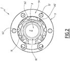
Fig 2 ] lafigure 2 est une vue de derrière du support de lafigure 1 ; - [
Fig 3 ] lafigure 3 est une vue de dessus du support desfigures 1 et2 ; et - [
Fig 4 ] lafigure 4 est une coupe selon le plan IV à lafigure 1 . - Un dispositif de pulvérisation 1 est partiellement représenté sur la
figure 1 . Ce dispositif 1 comprend un support 2, un robot 3 qui peut, par exemple, être un robot réciprocateur, ainsi qu'un pulvérisateur 4 muni d'au moins une buse 42 pour pulvériser un fluide. Pour plus de clarté, seule une partie du robot 3 est représentée, à savoir l'extrémité d'un bras de manipulation. Le robot 3 et le pulvérisateur 4 sont représentés transparents et en pointillés sur lafigure 1 et ne sont pas représentés sur les autres figures. - Le support 2 définit un axe longitudinal X, sur lequel sont alignés le robot 3 et le pulvérisateur 4.
- Le support 2 comprend, à l'une de ses extrémités, dite distale, un élément de fixation 5 au robot 3. Comme mieux visible sur la
figure 2 , cet élément de fixation 5 a une forme de fer à cheval, centré sur l'axe X, qui comprend des perçages 52 destinés à recevoir des vis 32 de fixation au robot 3, représentées par des traits d'axe à lafigure 1 . Dans l'exemple des figures, l'élément de fixation 5 comprend six perçages 52. L'élément de fixation 5 comprend également une surface d'appui 54 servant à positionner le support 2 sur le robot 3. - A son extrémité proximale, opposée à l'extrémité distale, le support 2 comprend un élément 6 de liaison au pulvérisateur 4. L'élément de fixation 6 comprend quatre pieds 62, chacun de ces pieds étant pourvu d'un orifice 64 pour le passage d'une vis pour la fixation du pulvérisateur 4 au support 2. Les pieds 62 sont reliés, par des ponts 68, à une bague 66 centrée sur l'axe X, les pieds 62 étant répartis régulièrement autour d'un cercle centré sur l'axe X et dont le diamètre est supérieur au diamètre de la bague 66. En outre, deux des pieds 62, dirigés vers le bas du support 2, sont reliés par un arc 69 dont la fonction est de positionner précisément un plan de pose non représenté sur les figures. Le plan de pose appartient au dispositif 1 et maintien des raccords destinés à acheminer le fluide et de l'air vers le pulvérisateur 4.
- Les éléments 5 et 6 du support 2 sont reliés par un cadre 7 qui forme une base du support 2. Le cadre 7 comprend quatre montants 72, chacun des montants 72 partant de l'un des pieds 62 pour rejoindre l'élément de fixation 5. Les montants 72 sont substantiellement rectilignes et parallèles à l'axe X.
- Ainsi, grâce aux éléments 5, 6 et 7, le support 2 permet d'effectuer une liaison entre le robot 3 et le pulvérisateur 4.
- La bague 66 est prolongée le long de l'axe X, en direction de l'élément de fixation 5, par un logement 8 de réception d'une unité haute tension non représentée. Ce logement 8 est un cylindre creux, dans l'exemple à base circulaire, dont l'une des extrémités est formée par la bague 66 et l'autre extrémité 82 se situe dans le plan de la surface d'appui 54. Le logement 8 est mieux visible sur la
figure 3 . - Comme visible sur la
figure 1 , un logement 10 est prévu pour unité basse tension, également non représentée. Ce logement 10 est fixé sous le logement 8 et comprend un espace 102, orthogonal à l'axe X, ainsi qu'un prolongement 104 parallèle à l'axe X. L'espace 102 et le prolongement 104 forment un unique volume de réception de l'unité basse tension, ce volume ayant une forme de T vue de dessous, selon une direction radiale à l'axe X. A l'extrémité du prolongement 104, un perçage 106 permet le passage d'un câble de connexion de l'unité basse tension avec l'unité haute tension. - En fonctionnement, l'unité haute tension est placée dans le logement 8. Cette unité haute tension est alimentée par un courant de basse tension fourni par l'unité basse tension. L'unité haute tension est usuellement composée de diodes permettant d'élever la tension du courant fourni par l'unité basse tension. L'unité basse tension est également utilisée pour relier l'ensemble formé par l'unité haute tension et l'unité basse tension à une masse. Pour relier l'unité haute tension et l'unité basse tension, en général, l'unité haute tension est munie d'une prise femelle compatible avec une prise mâle d'un connecteur appartenant à l'unité basse tension. Ce dispositif, formé des unités basse et haute tension, permet d'alimenter le pulvérisateur 4 en courant haute tension afin de charger des particules de peinture à pulvériser sortant de la buse 42, dans le cadre d'une application de produit de revêtement par voie électrostatique.
- Le produit de revêtement à appliquer au moyen du pulvérisateur est amené au pulvérisateur 4 par deux tuyaux d'acheminement 11, représentés par des traits d'axe sur la
figure 1 , guidés par un élément de guidage 12. Le fluide peut, par exemple, être un produit de revêtement tel qu'une peinture. L'élément de guidage 12 décrit une portion de cylindre centrée sur l'axe X et entourant en partie le logement 8. L'élément de guidage 12 est ouvert sur le dessous du support 2. En pratique, l'élément de guidage 12 est ouvert sur un angle compris entre 20° et 90° autour de l'axe X. De préférence, cet angle est de 65°. L'élément de guidage 12 comprend des creux 122, prévus pour maintenir les tuyaux 11, disposés, de préférence, en quinconce sur l'élément de guidage 12. Par « en quinconce », on entend que les deux tuyaux sont disposés alternativement dans les creux 122, sur la longueur de l'élément de guidage. Dans l'exemple des figures, l'élément de guidage 12 comprend six creux 122. Le guidage des tuyaux d'acheminement 11 dans ces creux 122 permet d'isoler électriquement les différents tuyaux entre eux pour qu'ils n'entrent pas en contact. En effet, un tel contact pourrait créer, localement, un arc dû à une différence de potentiel entre deux fluides ayant chacun leur résistivité propre et contenus dans les deux tuyaux. - Le produit contenu dans les tuyaux d'acheminent 11 étant porté à haute tension à proximité d'une tête du pulvérisateur 4 et mis à la masse à proximité du robot 3, il est nécessaire d'avoir une longueur suffisante de tuyaux d'acheminement 11 afin d'éviter tout rampage électrique. L'enroulement des tuyaux 11 autour de l'élément de guidage 12 permet d'augmenter la longueur des tuyaux d'acheminement 11 tout en limitant l'encombrement global du support 2. La longueur des tuyaux d'acheminement 11 dépend de la résistivité des fluides acheminés par ces tuyaux 11 et de la tension souhaitée. Par exemple, pour un fluide ayant une résistivité de 3 MOhm.cm et une tension de 100kV, il est nécessaire d'avoir des tuyaux d'acheminement 11 de 850 mm. A tension égale, plus la résistivité du fluide utilisé est grande, moins les tuyaux d'acheminement 11 doivent être longs.
- De plus, l'enroulement des tuyaux 11 autour de l'élément de guidage 12 permet d'éviter que des paillettes métalliques contenues dans certains fluides ne s'orientent dans la direction du champ électrique généré par l'unité haute tension. Ceci évite de générer un court-circuit intrinsèque au fluide.
- En pratique, afin que la longueur des tuyaux d'acheminement 11 soit suffisante et que l'encombrement du support 2 soit optimisé, l'élément de guidage 12 a un diamètre intérieur supérieur au diamètre extérieur du logement 8. En pratique, la distance d1 séparant le logement 8 et l'élément de guidage 12 est égale à la différence entre une valeur du rayon intérieur R12 de l'élément de guidage 12 et une valeur du rayon extérieur R8 du logement 8. Cette distance d1 est comprise entre 0,1 mm et 2 mm. De préférence, cette distance d1 est de 0,5 mm. Ainsi, un espace 14 d'épaisseur radiale d1 est formé entre l'élément de guidage 12 et le logement 8. Cet espace 14 est utilisé pour faire passer des tuyaux d'air 13 du robot 3 jusqu'au pulvérisateur 4. Ces tuyaux d'air 13, représentés par des traits d'axe sur la
figure 1 , sont utilisés pour alimenter une jupe d'air de conformation du jet de produit de revêtement sortant de la buse 42 du pulvérisateur 4, pour alimenter des vannes du pulvérisateur 4 et, éventuellement, pour alimenter et/ou freiner une turbine du pulvérisateur 4. - Afin de maintenir les tuyaux d'air 13 en place, un élément de retenue 16 est disposé sur l'extérieur du logement 8, entre l'élément de fixation 5 et l'élément de guidage 12. L'élément de retenue 16 décrit une portion de cercle autour du logement 8. Cette portion de cercle est délimitée par le logement 10 et comprend un logement 162 pour chaque tuyau d'air 13. Dans l'exemple des figures, l'élément de guidage comprend quinze logements 162 répartis autour de l'axe X pour accueillir quinze tuyaux d'air, seuls certains de ces logements étant visibles aux
figures 1 à 3 . - En pratique, le nombre de logements 162 n'est pas forcément égal à quinze. Par exemple, l'élément de guidage 12 peut comprendre jusqu'à vingt-cinq logements 162 ou, au contraire moins de dix tels logements. Afin d'identifier les tuyaux d'air 13, des marques d'identification 18 sont gravées sur l'extérieur de l'élément de fixation 5. Ainsi, les tuyaux 13 sont fixés, chacun, dans un logement 162, et longent ensuite le logement 8, en étant facilement repérables. Ils sont donc parallèles à l'axe X et chaque tuyau d'air passe à travers l'élément de fixation 5, sous l'une des marques d'identification 18. La forme de l'élément de guidage 16 permet de fixer rapidement les tuyaux d'air avant leur raccordement au pulvérisateur 4, en les clipsant à l'élément de guidage 16.
- Pour avoir un support 2 compact, il est façonné grâce à un procédé de fabrication additive. Ainsi, les logements 8 et 10, les éléments de liaison 5 et 6 et les éléments de support et de retenue 12 et 16 sont monoblocs. En d'autres termes, le support 2 est fabriqué d'un seul tenant venu de matière.
- Contrairement à un assemblage de pièces différentes, le procédé de fabrication additive, qui peut, par exemple, être un procédé de fabrication par fusion à jets multiples MJF (de l'anglais Multi Jet Fusion), permet d'optimiser l'encombrement du support 2, notamment en permettant de placer l'élément de retenue 16 entre l'élément de guidage 12 et l'élément de fixation 5. Le procédé de fabrication par fusion à jets multiples consiste à appliquer, pour chaque couche de la pièce à créer, un liant et un agent détaillant, dont la fonction est de lisser une surface, sur une surface à fusionner d'une poudre. Ensuite, un agent liquide est déposé afin de fusionner les particules désirées. Enfin, chaque couche de matériau est chauffée afin de former la pièce.
- De plus, les marques d'identification 18 sont intégrées directement au support 2 au cours de sa fabrication. Il n'y a donc pas besoin d'effectuer une étape supplémentaire pour les graver dans la pièce. Cela permet de gagner du temps supplémentaire lors de la fabrication du support 2 qui a donc un coût minoré.
- Afin de garder un coût de fabrication faible, tout en ayant de bonnes propriétés mécaniques, le support 2 est fabriqué en matériau synthétique, de préférence en polyamide 12. En effet, l'utilisation combinée de la fabrication additive avec le polyamide 12 permet d'avoir un support 2 léger et résistant aux solvants utilisés dans une installation de projection de produit de revêtement.
- En variante, le support 2 peut être fabriqué, par exemple, en polyoxyméthylène, en polyétheréthercétone ou en polytéréphtalate d'éthylène.
- Selon une autre variante, l'élément de fixation 5 de liaison au pulvérisateur comprend un nombre différent de perçages 52, par exemple 3 ou 10.
- En variante, le dispositif de pulvérisation comprend un nombre différent de tuyaux 11 d'acheminement de produit de revêtement au pulvérisateur 4, par exemple un ou 3. En général, le nombre de tuyaux d'acheminement 11 varie entre 1 et 4. Chaque tuyau d'acheminement 11 peut également être utilisé pour y faire circuler un produit de rinçage ou un solvant.
- En variante, le nombre de pieds 62 et le nombre de montants 72 peuvent varier. Par exemple, le support peut comprend cinq pieds 62 et cinq montants 72 ou trois pieds 62 et six montants 72.
- En variante, l'unité haute tension est remplacée par une prise haute tension, alimentée directement en courant haute tension. Dans ce cas, à la place de l'unité basse tension, un connecteur permet de relier l'unité haute tension à la masse.
- En variante, l'élément de guidage 12 peut comprendre un nombre différent de creux 122, par exemple quatre ou huit.
- Le mode de réalisation et les variantes mentionnés ci-dessus peuvent être combinés entre eux pour générer de nouveaux modes de réalisation de l'invention.
Claims (10)
- Support (2) pour pulvérisateur comprenant un logement (8) pour une unité ou une prise haute tension, un élément de guidage (12) pour au moins un tuyau (11) d'acheminement de produit de revêtement, un élément de retenue (16) pour des tuyaux d'air (13), un premier élément de fixation (5) à un robot (3) et un second élément de fixation (6) à un pulvérisateur (4), caractérisé en ce que le logement (8), l'élément de guidage (12), l'élément de retenue (16), le premier élément de fixation (5) et le second élément de fixation (6) sont monoblocs.
- Support (2) la revendications précédente, caractérisé en ce qu'il est fabriqué matériau synthétique, de préférence en polyamide 12, en polyoxyméthylène, en polyétheréthercétone ou en polytéréphtalate d'éthylène
- Support (2) selon l'une quelconque des revendications précédentes, caractérisé en ce qu'il comprend également un logement (10) pour une unité basse tension, également monobloc avec le reste du support.
- Support (2) selon l'une quelconque des revendications précédentes, caractérisé en ce le premier élément de fixation (5), l'élément de retenue (16) et le second élément de fixation (6) sont alignés, dans cet ordre, le long d'un axe (X) du support.
- Support (2) selon la revendication 4, caractérisé en ce que le logement (8) pour l'unité ou la prise haute tension est un cylindre de révolution aligné avec l'axe (X) du support.
- Support (2) selon la revendication 5, caractérisé en ce que le logement (8) pour l'unité ou la prise haute tension est situé entre le premier élément de fixation (5) et le second élément de fixation (6), en ce que l'élément de guidage (12) est centré sur l'axe (X) du support, en ce qu'il a un rayon intérieur (R12) de valeur supérieure à une valeur du rayon extérieur (R8) du logement (8) pour l'unité ou la prise haute tension et en ce que, de préférence, la différence (d1) entre la valeur du rayon intérieur de l'élément de guidage et la valeur du rayon extérieur du logement de l'unité haute tension est comprise entre 0,1 mm et 2 mm, de préférence de l'ordre de 0,5 mm.
- Support (2) selon l'une quelconque des revendications précédentes, caractérisé en ce qu'il comprend des marques (18) d'identification des tuyaux d'air (13).
- Dispositif (1) de pulvérisation comprenant un pulvérisateur (4), un robot (3), ainsi qu'un support (2) pour pulvérisateur, le pulvérisateur étant relié au robot par le support pour pulvérisateur, caractérisé en ce que le support pour pulvérisateur (2) est selon l'une quelconque des revendications précédentes.
- Dispositif (1) selon la revendication 8, caractérisé en ce qu'il comprend des tuyaux d'airs (13) maintenus en place par l'élément de retenue (16) et au moins un tuyau (11) d'acheminement de produit de revêtement guidé par l'élément de guidage (12).
- Procédé de fabrication d'un support (2) selon l'une des revendications 1 à 7, caractérisé en ce qu'il s'agit d'un procédé de fabrication additive par fusion à jets multiples.
Applications Claiming Priority (1)
| Application Number | Priority Date | Filing Date | Title |
|---|---|---|---|
| FR2003783A FR3109323B1 (fr) | 2020-04-15 | 2020-04-15 | Support pour pulvérisateur et dispositif de pulvérisation comprenant un tel support |
Publications (3)
| Publication Number | Publication Date |
|---|---|
| EP3895810A1 true EP3895810A1 (fr) | 2021-10-20 |
| EP3895810C0 EP3895810C0 (fr) | 2025-03-05 |
| EP3895810B1 EP3895810B1 (fr) | 2025-03-05 |
Family
ID=71784206
Family Applications (1)
| Application Number | Title | Priority Date | Filing Date |
|---|---|---|---|
| EP21168415.4A Active EP3895810B1 (fr) | 2020-04-15 | 2021-04-14 | Support pour pulvérisateur, dispositif de pulvérisation comprenant un tel support et procédé de fabrication d'un tel support |
Country Status (6)
| Country | Link |
|---|---|
| US (1) | US11951499B2 (fr) |
| EP (1) | EP3895810B1 (fr) |
| JP (1) | JP7780258B2 (fr) |
| KR (1) | KR20210127881A (fr) |
| CN (1) | CN113522582B (fr) |
| FR (1) | FR3109323B1 (fr) |
Families Citing this family (1)
| Publication number | Priority date | Publication date | Assignee | Title |
|---|---|---|---|---|
| FR3135405A1 (fr) * | 2022-05-16 | 2023-11-17 | Exel Industries | Guide de conformation d’un tuyau, pulvérisateur de produit de revêtement comprenant un tel guide et installation d’application de produit de revêtement comprenant un tel pulvérisateur |
Citations (2)
| Publication number | Priority date | Publication date | Assignee | Title |
|---|---|---|---|---|
| FR2644322A1 (fr) * | 1989-03-20 | 1990-09-21 | Gence Stephane | Systeme d'accrochage pour les pistolets de pulverisation des pis de vaches |
| CN108372057A (zh) * | 2018-04-17 | 2018-08-07 | 曹国平 | 一种用于烤漆房内部喷漆头的固定支架 |
Family Cites Families (14)
| Publication number | Priority date | Publication date | Assignee | Title |
|---|---|---|---|---|
| US4520949A (en) * | 1983-04-11 | 1985-06-04 | Champion Spark Plug Company | Protective housing for coating applicator |
| US4555058A (en) * | 1983-10-05 | 1985-11-26 | Champion Spark Plug Company | Rotary atomizer coater |
| JPS6328151U (fr) * | 1986-08-06 | 1988-02-24 | ||
| US5853126A (en) * | 1997-02-05 | 1998-12-29 | Illinois Tool Works, Inc. | Quick disconnect for powder coating apparatus |
| FR2797789B1 (fr) * | 1999-08-30 | 2001-11-23 | Sames Sa | Procede et dispositif de montage d'un sous-ensemble comprenant au moins un projecteur de produit de revetement sur une partie mobile d'un robot |
| JP4705100B2 (ja) * | 2005-06-02 | 2011-06-22 | Abb株式会社 | 回転霧化頭型塗装機 |
| CN102632000B (zh) * | 2007-09-20 | 2015-04-01 | 本田技研工业株式会社 | 涂敷装置 |
| JP2009072704A (ja) * | 2007-09-20 | 2009-04-09 | Honda Motor Co Ltd | 塗装装置 |
| DE102014003931B3 (de) * | 2014-03-18 | 2015-09-24 | Dürr Systems GmbH | Roboteranordnung mit paarweise aneinander angepasstem Applikationsgerät mit Zwischenflansch und entsprechendes Montageverfahren |
| GB2531576B (en) * | 2014-10-22 | 2018-04-25 | Q Bot Ltd | Modular Robot |
| FR3042390B1 (fr) * | 2015-10-15 | 2017-11-24 | Albea Le Treport | Flacon et procede de fabrication d'un tube plongeur pour flacon |
| CA3040596A1 (fr) * | 2016-10-17 | 2018-04-26 | 9376-4058 Quebec Inc. | Casque, procede de conception et de fabrication d'un casque et casque fabrique selon ce procede |
| JP7307730B2 (ja) * | 2017-12-30 | 2023-07-12 | ディエルエイチ・ボウルズ・インコーポレイテッド | 自動車の画像センサー表面の洗浄乾燥システム |
| CN110404712A (zh) * | 2019-08-05 | 2019-11-05 | 广东博智林机器人有限公司 | 喷涂机器人及喷涂系统 |
-
2020
- 2020-04-15 FR FR2003783A patent/FR3109323B1/fr active Active
-
2021
- 2021-04-08 JP JP2021065975A patent/JP7780258B2/ja active Active
- 2021-04-09 CN CN202110381275.4A patent/CN113522582B/zh active Active
- 2021-04-11 US US17/227,367 patent/US11951499B2/en active Active
- 2021-04-12 KR KR1020210047307A patent/KR20210127881A/ko active Pending
- 2021-04-14 EP EP21168415.4A patent/EP3895810B1/fr active Active
Patent Citations (2)
| Publication number | Priority date | Publication date | Assignee | Title |
|---|---|---|---|---|
| FR2644322A1 (fr) * | 1989-03-20 | 1990-09-21 | Gence Stephane | Systeme d'accrochage pour les pistolets de pulverisation des pis de vaches |
| CN108372057A (zh) * | 2018-04-17 | 2018-08-07 | 曹国平 | 一种用于烤漆房内部喷漆头的固定支架 |
Also Published As
| Publication number | Publication date |
|---|---|
| FR3109323A1 (fr) | 2021-10-22 |
| EP3895810C0 (fr) | 2025-03-05 |
| CN113522582B (zh) | 2025-10-28 |
| JP7780258B2 (ja) | 2025-12-04 |
| KR20210127881A (ko) | 2021-10-25 |
| US11951499B2 (en) | 2024-04-09 |
| EP3895810B1 (fr) | 2025-03-05 |
| FR3109323B1 (fr) | 2022-09-23 |
| US20210323019A1 (en) | 2021-10-21 |
| CN113522582A (zh) | 2021-10-22 |
| JP2021169081A (ja) | 2021-10-28 |
Similar Documents
| Publication | Publication Date | Title |
|---|---|---|
| EP3831497B1 (fr) | Projecteur électrostatique rotatif de produit de revêtement et installation de projection comprenant un tel projecteur | |
| FR2692501A1 (fr) | Dispositif de projection électrostatique de produit de revêtement liquide à tête de pulvérisation rotative. | |
| JPH11505173A (ja) | 回転式ディストリビュータを備えた粉体スプレガン | |
| FR3027007A1 (fr) | Dispositif de nettoyage d’une camera d’aide a la conduite d’un vehicule automobile | |
| EP3895810B1 (fr) | Support pour pulvérisateur, dispositif de pulvérisation comprenant un tel support et procédé de fabrication d'un tel support | |
| FR2876600A1 (fr) | Dispositif de pulverisation electrostatique | |
| FR3039864A1 (fr) | Procede de fabrication d'un dispositif de poulie, dispositif de poulie selon un tel procede de fabrication et moteur equipe d'une telle poulie | |
| WO2015022330A1 (fr) | Pulverisateur d'un produit lubrifiant et installation de lubrification comprenant ce pulverisateur | |
| FR2945461A1 (fr) | Projecteur et organe de pulverisation de produit de revetement et procede de projection mettant en oeuvre un tel projecteur. | |
| EP2361157B1 (fr) | Projecteur de produit de revetement | |
| FR3147058A1 (fr) | Ensemble de brosse de mise à la terre | |
| EP3873677A1 (fr) | Bol de pulvérisation de produit de revêtement, projecteur rotatif incluant un tel bol et procédé de nettoyage d'un tel projecteur | |
| EP3831499B1 (fr) | Projecteur électrostatique rotatif de produit de revêtement, installation de projection comprenant un tel projecteur et procédé de revêtement au moyen d'un tel projecteur | |
| EP3996853B1 (fr) | Installation de projection de fluide | |
| EP4279783A1 (fr) | Guide de conformation d'un tuyau, pulvérisateur de produit de revêtement comprenant un tel guide et installation d'application de produit de revêtement comprenant un tel pulvérisateur | |
| EP3820623A1 (fr) | Turbine pour dispositif de projection de fluide, dispositif de projection de fluide, ainsi qu'ensemble comprenant un tel dispositif et un outil | |
| EP1068022A1 (fr) | Bol de pulverisation et projecteur rotatif electrostatique equipe d'un tel bol | |
| WO2020011965A1 (fr) | Turbine, dispositif de projection de fluide, installation et procédé de fabrication associés | |
| FR3147057A1 (fr) | Ensemble de brosse de mise à la terre | |
| EP4234099A1 (fr) | Dispositif d'alimentation d'un pulvérisateur, modules pour un tel dispositif d'alimentation et installation d'application de produit de revêtement comprenant un tel dispositif d'alimentation | |
| WO2006123032A1 (fr) | Buse a chambre tourbillonnaire | |
| EP3953051B1 (fr) | Buse en deux pièces pour diffuseurs d'aérosol | |
| FR3152666A1 (fr) | Ensemble de brosse de mise à la terre | |
| FR2657124A1 (fr) | Soupape de dispositif d'alimentation de moteur a combustion interne. | |
| FR3152664A1 (fr) | Ensemble de brosse de mise à la terre |
Legal Events
| Date | Code | Title | Description |
|---|---|---|---|
| PUAI | Public reference made under article 153(3) epc to a published international application that has entered the european phase |
Free format text: ORIGINAL CODE: 0009012 |
|
| STAA | Information on the status of an ep patent application or granted ep patent |
Free format text: STATUS: THE APPLICATION HAS BEEN PUBLISHED |
|
| AK | Designated contracting states |
Kind code of ref document: A1 Designated state(s): AL AT BE BG CH CY CZ DE DK EE ES FI FR GB GR HR HU IE IS IT LI LT LU LV MC MK MT NL NO PL PT RO RS SE SI SK SM TR |
|
| B565 | Issuance of search results under rule 164(2) epc |
Effective date: 20210915 |
|
| STAA | Information on the status of an ep patent application or granted ep patent |
Free format text: STATUS: REQUEST FOR EXAMINATION WAS MADE |
|
| 17P | Request for examination filed |
Effective date: 20220330 |
|
| RBV | Designated contracting states (corrected) |
Designated state(s): AL AT BE BG CH CY CZ DE DK EE ES FI FR GB GR HR HU IE IS IT LI LT LU LV MC MK MT NL NO PL PT RO RS SE SI SK SM TR |
|
| RIN1 | Information on inventor provided before grant (corrected) |
Inventor name: PERINET, SYLVAIN Inventor name: VANZETTO, DENIS |
|
| GRAP | Despatch of communication of intention to grant a patent |
Free format text: ORIGINAL CODE: EPIDOSNIGR1 |
|
| STAA | Information on the status of an ep patent application or granted ep patent |
Free format text: STATUS: GRANT OF PATENT IS INTENDED |
|
| INTG | Intention to grant announced |
Effective date: 20241115 |
|
| GRAS | Grant fee paid |
Free format text: ORIGINAL CODE: EPIDOSNIGR3 |
|
| GRAA | (expected) grant |
Free format text: ORIGINAL CODE: 0009210 |
|
| STAA | Information on the status of an ep patent application or granted ep patent |
Free format text: STATUS: THE PATENT HAS BEEN GRANTED |
|
| AK | Designated contracting states |
Kind code of ref document: B1 Designated state(s): AL AT BE BG CH CY CZ DE DK EE ES FI FR GB GR HR HU IE IS IT LI LT LU LV MC MK MT NL NO PL PT RO RS SE SI SK SM TR |
|
| REG | Reference to a national code |
Ref country code: GB Ref legal event code: FG4D Free format text: NOT ENGLISH |
|
| REG | Reference to a national code |
Ref country code: CH Ref legal event code: EP |
|
| REG | Reference to a national code |
Ref country code: IE Ref legal event code: FG4D Free format text: LANGUAGE OF EP DOCUMENT: FRENCH |
|
| REG | Reference to a national code |
Ref country code: DE Ref legal event code: R096 Ref document number: 602021027006 Country of ref document: DE |
|
| U01 | Request for unitary effect filed |
Effective date: 20250313 |
|
| U07 | Unitary effect registered |
Designated state(s): AT BE BG DE DK EE FI FR IT LT LU LV MT NL PT RO SE SI Effective date: 20250320 |
|
| U20 | Renewal fee for the european patent with unitary effect paid |
Year of fee payment: 5 Effective date: 20250325 |
|
| PG25 | Lapsed in a contracting state [announced via postgrant information from national office to epo] |
Ref country code: RS Free format text: LAPSE BECAUSE OF FAILURE TO SUBMIT A TRANSLATION OF THE DESCRIPTION OR TO PAY THE FEE WITHIN THE PRESCRIBED TIME-LIMIT Effective date: 20250605 |
|
| PG25 | Lapsed in a contracting state [announced via postgrant information from national office to epo] |
Ref country code: ES Free format text: LAPSE BECAUSE OF FAILURE TO SUBMIT A TRANSLATION OF THE DESCRIPTION OR TO PAY THE FEE WITHIN THE PRESCRIBED TIME-LIMIT Effective date: 20250305 |
|
| PG25 | Lapsed in a contracting state [announced via postgrant information from national office to epo] |
Ref country code: NO Free format text: LAPSE BECAUSE OF FAILURE TO SUBMIT A TRANSLATION OF THE DESCRIPTION OR TO PAY THE FEE WITHIN THE PRESCRIBED TIME-LIMIT Effective date: 20250605 |
|
| PG25 | Lapsed in a contracting state [announced via postgrant information from national office to epo] |
Ref country code: HR Free format text: LAPSE BECAUSE OF FAILURE TO SUBMIT A TRANSLATION OF THE DESCRIPTION OR TO PAY THE FEE WITHIN THE PRESCRIBED TIME-LIMIT Effective date: 20250305 |
|
| PG25 | Lapsed in a contracting state [announced via postgrant information from national office to epo] |
Ref country code: GR Free format text: LAPSE BECAUSE OF FAILURE TO SUBMIT A TRANSLATION OF THE DESCRIPTION OR TO PAY THE FEE WITHIN THE PRESCRIBED TIME-LIMIT Effective date: 20250606 |
|
| PG25 | Lapsed in a contracting state [announced via postgrant information from national office to epo] |
Ref country code: SM Free format text: LAPSE BECAUSE OF FAILURE TO SUBMIT A TRANSLATION OF THE DESCRIPTION OR TO PAY THE FEE WITHIN THE PRESCRIBED TIME-LIMIT Effective date: 20250305 |
|
| PG25 | Lapsed in a contracting state [announced via postgrant information from national office to epo] |
Ref country code: PL Free format text: LAPSE BECAUSE OF FAILURE TO SUBMIT A TRANSLATION OF THE DESCRIPTION OR TO PAY THE FEE WITHIN THE PRESCRIBED TIME-LIMIT Effective date: 20250305 |
|
| PG25 | Lapsed in a contracting state [announced via postgrant information from national office to epo] |
Ref country code: CZ Free format text: LAPSE BECAUSE OF FAILURE TO SUBMIT A TRANSLATION OF THE DESCRIPTION OR TO PAY THE FEE WITHIN THE PRESCRIBED TIME-LIMIT Effective date: 20250305 |
|
| PG25 | Lapsed in a contracting state [announced via postgrant information from national office to epo] |
Ref country code: SK Free format text: LAPSE BECAUSE OF FAILURE TO SUBMIT A TRANSLATION OF THE DESCRIPTION OR TO PAY THE FEE WITHIN THE PRESCRIBED TIME-LIMIT Effective date: 20250305 |
|
| PG25 | Lapsed in a contracting state [announced via postgrant information from national office to epo] |
Ref country code: IS Free format text: LAPSE BECAUSE OF FAILURE TO SUBMIT A TRANSLATION OF THE DESCRIPTION OR TO PAY THE FEE WITHIN THE PRESCRIBED TIME-LIMIT Effective date: 20250705 |
|
| REG | Reference to a national code |
Ref country code: CH Ref legal event code: H13 Free format text: ST27 STATUS EVENT CODE: U-0-0-H10-H13 (AS PROVIDED BY THE NATIONAL OFFICE) Effective date: 20251125 |
|
| PG25 | Lapsed in a contracting state [announced via postgrant information from national office to epo] |
Ref country code: MC Free format text: LAPSE BECAUSE OF FAILURE TO SUBMIT A TRANSLATION OF THE DESCRIPTION OR TO PAY THE FEE WITHIN THE PRESCRIBED TIME-LIMIT Effective date: 20250305 |
|
| PLBE | No opposition filed within time limit |
Free format text: ORIGINAL CODE: 0009261 |
|
| STAA | Information on the status of an ep patent application or granted ep patent |
Free format text: STATUS: NO OPPOSITION FILED WITHIN TIME LIMIT |
|
| REG | Reference to a national code |
Ref country code: CH Ref legal event code: L10 Free format text: ST27 STATUS EVENT CODE: U-0-0-L10-L00 (AS PROVIDED BY THE NATIONAL OFFICE) Effective date: 20260114 |
|
| PG25 | Lapsed in a contracting state [announced via postgrant information from national office to epo] |
Ref country code: CH Free format text: LAPSE BECAUSE OF NON-PAYMENT OF DUE FEES Effective date: 20250430 |
|
| 26N | No opposition filed |
Effective date: 20251208 |
|
| PG25 | Lapsed in a contracting state [announced via postgrant information from national office to epo] |
Ref country code: IE Free format text: LAPSE BECAUSE OF NON-PAYMENT OF DUE FEES Effective date: 20250414 |
|
| U20 | Renewal fee for the european patent with unitary effect paid |
Year of fee payment: 6 Effective date: 20260326 |
|
| PG25 | Lapsed in a contracting state [announced via postgrant information from national office to epo] |
Ref country code: CY Free format text: LAPSE BECAUSE OF FAILURE TO SUBMIT A TRANSLATION OF THE DESCRIPTION OR TO PAY THE FEE WITHIN THE PRESCRIBED TIME-LIMIT Effective date: 20250305 |
|
| PGFP | Annual fee paid to national office [announced via postgrant information from national office to epo] |
Ref country code: GB Payment date: 20260430 Year of fee payment: 6 |