EP3895644A1 - Chirurgisches instrument - Google Patents
Chirurgisches instrument Download PDFInfo
- Publication number
- EP3895644A1 EP3895644A1 EP20169631.7A EP20169631A EP3895644A1 EP 3895644 A1 EP3895644 A1 EP 3895644A1 EP 20169631 A EP20169631 A EP 20169631A EP 3895644 A1 EP3895644 A1 EP 3895644A1
- Authority
- EP
- European Patent Office
- Prior art keywords
- coupling member
- actuating element
- surgical instrument
- tool
- longitudinal
- Prior art date
- Legal status (The legal status is an assumption and is not a legal conclusion. Google has not performed a legal analysis and makes no representation as to the accuracy of the status listed.)
- Pending
Links
Images



Classifications
-
- A—HUMAN NECESSITIES
- A61—MEDICAL OR VETERINARY SCIENCE; HYGIENE
- A61B—DIAGNOSIS; SURGERY; IDENTIFICATION
- A61B17/00—Surgical instruments, devices or methods
- A61B17/32—Surgical cutting instruments
- A61B17/3209—Incision instruments
-
- A—HUMAN NECESSITIES
- A61—MEDICAL OR VETERINARY SCIENCE; HYGIENE
- A61B—DIAGNOSIS; SURGERY; IDENTIFICATION
- A61B18/00—Surgical instruments, devices or methods for transferring non-mechanical forms of energy to or from the body
- A61B18/04—Surgical instruments, devices or methods for transferring non-mechanical forms of energy to or from the body by heating
- A61B18/12—Surgical instruments, devices or methods for transferring non-mechanical forms of energy to or from the body by heating by passing a current through the tissue to be heated, e.g. high-frequency current
- A61B18/14—Probes or electrodes therefor
- A61B18/1442—Probes having pivoting end effectors, e.g. forceps
- A61B18/1445—Probes having pivoting end effectors, e.g. forceps at the distal end of a shaft, e.g. forceps or scissors at the end of a rigid rod
-
- A—HUMAN NECESSITIES
- A61—MEDICAL OR VETERINARY SCIENCE; HYGIENE
- A61B—DIAGNOSIS; SURGERY; IDENTIFICATION
- A61B18/00—Surgical instruments, devices or methods for transferring non-mechanical forms of energy to or from the body
- A61B18/04—Surgical instruments, devices or methods for transferring non-mechanical forms of energy to or from the body by heating
- A61B18/12—Surgical instruments, devices or methods for transferring non-mechanical forms of energy to or from the body by heating by passing a current through the tissue to be heated, e.g. high-frequency current
- A61B18/14—Probes or electrodes therefor
- A61B18/1442—Probes having pivoting end effectors, e.g. forceps
-
- A—HUMAN NECESSITIES
- A61—MEDICAL OR VETERINARY SCIENCE; HYGIENE
- A61B—DIAGNOSIS; SURGERY; IDENTIFICATION
- A61B17/00—Surgical instruments, devices or methods
- A61B17/28—Surgical forceps
- A61B17/2812—Surgical forceps with a single pivotal connection
- A61B17/2816—Pivots
-
- A—HUMAN NECESSITIES
- A61—MEDICAL OR VETERINARY SCIENCE; HYGIENE
- A61B—DIAGNOSIS; SURGERY; IDENTIFICATION
- A61B17/00—Surgical instruments, devices or methods
- A61B17/28—Surgical forceps
- A61B17/285—Surgical forceps combined with cutting implements
-
- A—HUMAN NECESSITIES
- A61—MEDICAL OR VETERINARY SCIENCE; HYGIENE
- A61B—DIAGNOSIS; SURGERY; IDENTIFICATION
- A61B18/00—Surgical instruments, devices or methods for transferring non-mechanical forms of energy to or from the body
-
- A—HUMAN NECESSITIES
- A61—MEDICAL OR VETERINARY SCIENCE; HYGIENE
- A61B—DIAGNOSIS; SURGERY; IDENTIFICATION
- A61B18/00—Surgical instruments, devices or methods for transferring non-mechanical forms of energy to or from the body
- A61B18/04—Surgical instruments, devices or methods for transferring non-mechanical forms of energy to or from the body by heating
- A61B18/12—Surgical instruments, devices or methods for transferring non-mechanical forms of energy to or from the body by heating by passing a current through the tissue to be heated, e.g. high-frequency current
- A61B18/14—Probes or electrodes therefor
- A61B18/1482—Probes or electrodes therefor having a long rigid shaft for accessing the inner body transcutaneously in minimal invasive surgery, e.g. laparoscopy
-
- A—HUMAN NECESSITIES
- A61—MEDICAL OR VETERINARY SCIENCE; HYGIENE
- A61B—DIAGNOSIS; SURGERY; IDENTIFICATION
- A61B17/00—Surgical instruments, devices or methods
- A61B17/28—Surgical forceps
- A61B17/2812—Surgical forceps with a single pivotal connection
- A61B17/2841—Handles
- A61B2017/2845—Handles with a spring pushing the handle back
-
- A—HUMAN NECESSITIES
- A61—MEDICAL OR VETERINARY SCIENCE; HYGIENE
- A61B—DIAGNOSIS; SURGERY; IDENTIFICATION
- A61B18/00—Surgical instruments, devices or methods for transferring non-mechanical forms of energy to or from the body
- A61B2018/00053—Mechanical features of the instrument of device
- A61B2018/00172—Connectors and adapters therefor
-
- A—HUMAN NECESSITIES
- A61—MEDICAL OR VETERINARY SCIENCE; HYGIENE
- A61B—DIAGNOSIS; SURGERY; IDENTIFICATION
- A61B18/00—Surgical instruments, devices or methods for transferring non-mechanical forms of energy to or from the body
- A61B2018/00053—Mechanical features of the instrument of device
- A61B2018/00184—Moving parts
- A61B2018/00196—Moving parts reciprocating lengthwise
-
- A—HUMAN NECESSITIES
- A61—MEDICAL OR VETERINARY SCIENCE; HYGIENE
- A61B—DIAGNOSIS; SURGERY; IDENTIFICATION
- A61B18/00—Surgical instruments, devices or methods for transferring non-mechanical forms of energy to or from the body
- A61B2018/00053—Mechanical features of the instrument of device
- A61B2018/00184—Moving parts
- A61B2018/00202—Moving parts rotating
-
- A—HUMAN NECESSITIES
- A61—MEDICAL OR VETERINARY SCIENCE; HYGIENE
- A61B—DIAGNOSIS; SURGERY; IDENTIFICATION
- A61B18/00—Surgical instruments, devices or methods for transferring non-mechanical forms of energy to or from the body
- A61B2018/00571—Surgical instruments, devices or methods for transferring non-mechanical forms of energy to or from the body for achieving a particular surgical effect
- A61B2018/00601—Cutting
-
- A—HUMAN NECESSITIES
- A61—MEDICAL OR VETERINARY SCIENCE; HYGIENE
- A61B—DIAGNOSIS; SURGERY; IDENTIFICATION
- A61B18/00—Surgical instruments, devices or methods for transferring non-mechanical forms of energy to or from the body
- A61B18/04—Surgical instruments, devices or methods for transferring non-mechanical forms of energy to or from the body by heating
- A61B18/12—Surgical instruments, devices or methods for transferring non-mechanical forms of energy to or from the body by heating by passing a current through the tissue to be heated, e.g. high-frequency current
- A61B18/14—Probes or electrodes therefor
- A61B2018/1405—Electrodes having a specific shape
- A61B2018/1412—Blade
-
- A—HUMAN NECESSITIES
- A61—MEDICAL OR VETERINARY SCIENCE; HYGIENE
- A61B—DIAGNOSIS; SURGERY; IDENTIFICATION
- A61B18/00—Surgical instruments, devices or methods for transferring non-mechanical forms of energy to or from the body
- A61B18/04—Surgical instruments, devices or methods for transferring non-mechanical forms of energy to or from the body by heating
- A61B18/12—Surgical instruments, devices or methods for transferring non-mechanical forms of energy to or from the body by heating by passing a current through the tissue to be heated, e.g. high-frequency current
- A61B18/14—Probes or electrodes therefor
- A61B18/1442—Probes having pivoting end effectors, e.g. forceps
- A61B2018/1452—Probes having pivoting end effectors, e.g. forceps including means for cutting
- A61B2018/1455—Probes having pivoting end effectors, e.g. forceps including means for cutting having a moving blade for cutting tissue grasped by the jaws
-
- A—HUMAN NECESSITIES
- A61—MEDICAL OR VETERINARY SCIENCE; HYGIENE
- A61B—DIAGNOSIS; SURGERY; IDENTIFICATION
- A61B18/00—Surgical instruments, devices or methods for transferring non-mechanical forms of energy to or from the body
- A61B18/04—Surgical instruments, devices or methods for transferring non-mechanical forms of energy to or from the body by heating
- A61B18/12—Surgical instruments, devices or methods for transferring non-mechanical forms of energy to or from the body by heating by passing a current through the tissue to be heated, e.g. high-frequency current
- A61B18/14—Probes or electrodes therefor
- A61B2018/1475—Electrodes retractable in or deployable from a housing
Definitions
- the invention relates to a surgical instrument, for example an electrosurgical instrument.
- the surgical instrument can have two branches pivotably mounted on one another.
- a tool for example a knife, is provided on the surgical instrument and is movably supported in a longitudinal direction.
- the knife can be stored in a knife channel.
- the knife can be moved in the longitudinal direction via an actuating element, for example in order to cut through biological tissue jammed between the branches.
- EP 2 436 327 A1 describes a surgical clamp with two branches pivotably mounted on one another and a knife guided in a longitudinal direction.
- the knife can be moved in the longitudinal direction via a pivotably mounted actuating element.
- a helical spring is provided which is subjected to tension when the actuating element is deflected from its initial position and which generates a restoring torque in the direction of the initial position.
- US 2017/0209205 A1 describes a bipolar surgical clamp with two branches pivotably mounted on one another and a knife mounted in a longitudinal direction.
- the knife can be moved in the longitudinal direction via an actuating element.
- the actuation element is coupled in terms of movement to the knife via a coupling device, wherein the coupling device has a telescopic lever in order to be able to keep the space required for the pivoting movement small when the actuating element is pivoted about a pivot axis.
- the telescopic lever is first retracted upon contact with a housing wall and then extended again.
- the housing should be able to be kept small.
- the surgical instrument according to the invention has a tool, for example a knife, which is arranged to be movable in a longitudinal direction.
- An actuating element is provided for actuating the tool.
- the actuator is pivoted. It can be swiveled between a starting position and a working position.
- a coupling device is used to produce a movement coupling between the actuating element and the tool.
- the coupling device has a coupling member.
- the coupling member is set up to transmit the pivoting movement of the actuating element to the tool and / or a part, in particular immovably connected to the tool.
- the coupling member forms a connecting rod of the coupling device.
- the connecting rod which is preferably formed by the coupling member, is mounted at one end in order to carry out a rotary movement or pivoting movement and is mounted at the other end in order to carry out a substantially rectilinear movement in the longitudinal direction.
- the coupling member is elastically deformable.
- the coupling member In the starting position of the actuating element, the coupling member is preferably not elastically deformed or elastically deformed to a lesser extent than in the working position of the actuating element and assumes a first state.
- the coupling member In the working position of the actuating element, the coupling member is elastically more deformed than in its first state and causes a restoring torque on the pivotably mounted actuating element in the direction of the starting position.
- the state of the elastically deformed coupling member in the working position of the actuating element is referred to as the second state.
- the coupling member itself effects the restoring torque on the actuating element in order to move it back into the starting position.
- additional Elements for generating the restoring torque and in particular helical springs can be dispensed with.
- This releasable connection can in particular be force-fit and / or form-fit and can be implemented, for example, by a latching connection.
- a releasable connection can also be present at another point on the coupling device, for example at the connection between the coupling device and the actuating element.
- the releasable connection can be realized by a groove in the tool, into which the coupling device or the coupling member engages.
- An elastic deformation force in the first state of the coupling member brings about at least one non-positive connection.
- the tool In the starting position of the actuating element, the tool preferably assumes a retracted position. In the working position of the actuating element, the tool can assume an extended position. In a retracted position, the tool has no influence on biological tissue. In an extended position, the tool can act on biological tissue.
- the surgical instrument can preferably have two branches pivotably mounted on one another.
- the tool is mounted to be movable in the longitudinal direction in one of the branches, for example in a tool channel.
- the tool can be a knife, the tool channel forming a knife channel.
- a knife can cut biological tissue in the extended position.
- the coupling member for example the connecting rod, preferably connects two parts arranged at a distance from one another. These parts can be formed by the actuating element or a part coupled with movement on the one hand and by the tool or a connection part coupled in movement with it on the other hand. Without the coupling member, the transfer of motion from the actuating element to the tool would not be possible.
- the coupling member is in particular formed integrally in one piece. It is made from an elastically deformable material, for example from a metallic material, in particular a metallic alloy. It can optionally be provided with a protective layer in order to protect the coupling member against chemical effects, the protective layer having no significance for the movement coupling.
- one end of the coupling member is attached directly to the actuating element at a distance from the pivot axis of the actuating element.
- the coupling member can be arranged directly with the tool or with a connection part coupled with the movement.
- the connecting part is immobile on the tool arranged.
- the coupling member can be set up to translate a pivoting movement of the actuating element into a linear movement of the tool.
- the coupling member can be the only part that is available for the translation of the pivoting movement into the linear movement.
- the coupling member has a bow-shaped shape. It can, for example, be designed as a wire bracket or a punching bracket.
- the coupling member can have at least one longitudinal limb and an adjoining transverse limb.
- the transverse leg extends in particular at right angles to the direction of movement of the tool, that is to say at right angles to the longitudinal direction.
- the at least one longitudinal leg preferably extends at an angle inclined to the longitudinal direction, which has an amount between 0 degrees and 90 degrees, preferably between 10 degrees and 80 degrees and more preferably between 20 degrees and 70 degrees.
- the coupling member has two and in particular exactly two longitudinal legs which are connected to one another via the transverse leg.
- the transverse leg preferably forms one end of the coupling member and in particular the end that is assigned to the tool.
- Each longitudinal limb can have a free limb end, which are preferably not directly connected to one another and further preferably do not bear directly on one another.
- the free leg ends of the longitudinal legs are arranged offset from one another in a plane which is oriented at right angles to the transverse direction.
- the free leg ends are arranged within this plane along a common straight line in the direction of extent of the longitudinal legs when the coupling member is in an undeformed rest state, which can for example correspond to the first state.
- the longitudinal legs of the coupling member can be of different lengths.
- the longitudinal limb and the transverse limb extend in a common plane in the starting position of the actuating element. Outside the starting position and in particular in the working position of the actuating element, the longitudinal legs can enclose an angle greater than zero. The included angle between the longitudinal legs is greatest in the working position and decreases towards the starting position, whereby it is preferably zero in the starting position.
- the longitudinal legs in the second state of the coupling member are elastically undeformed compared to the first state of the coupling member (starting position of the actuating element).
- the longitudinal limbs extend in a straight line in the first state of the coupling member, for example, they preferably also extend essentially in a straight line in the second state of the coupling member.
- the longitudinal legs can therefore in particular be rigid with respect to a bend transversely to their direction of extension.
- a force acting on the tool from the outside in the longitudinal direction can be very effective via the coupling member on the actuating element be supported.
- the tool is thus not undesirably pushed back from its extended position into the retracted position.
- This support effect is improved in particular when the longitudinal legs enclose an angle greater than zero in the working position.
- the angle between the longitudinal legs is measured in a projection plane which is oriented at right angles to the transverse direction and thus at right angles to the transverse leg.
- the transverse leg is preferably twisted about its direction of extension in the second state of the coupling member (working position of the actuating element). This torsion generates a torque on the at least one longitudinal leg connected to the transverse leg, as a result of which the restoring torque is brought about.
- the coupling member extends in a straight line or less curved between its two ends in the first state than in the second state. At least in the second state, the coupling member can extend in a curved manner between its two ends.
- the coupling member can have a bow-shaped shape or be designed as a flat element in the manner of a leaf spring.
- the coupling member can be fastened non-rotatably at one end or at both ends, in particular non-rotatably with the actuating element at one end and / or at the other end non-rotatably with the tool or with a connection part connected in particular immovably to the tool.
- the coupling member which is elastically deformed at least outside of its first state, can exert a force or force component at right angles to the longitudinal direction and in particular also at right angles to the transverse direction on the tool or a connecting part connected to the tool. In this way it is possible, for example, to lock the tool or the connecting part in at least one predetermined position in the longitudinal direction.
- the surgical instrument 20 can be designed as an electrosurgical instrument. It can be a monopolar or a bipolar electrosurgical instrument.
- the surgical instrument is designed in particular as a reusable instrument. It must therefore be cleaned and sterilized after each use.
- the surgical instrument 20 has two branches 21, 22 pivotably mounted on one another.
- Each branch 21, 22 has a tissue contact surface 21a and 22a, respectively.
- the branches 21, 22 can be moved towards or away from one another in order to pinch or let go of a biological tissue between the tissue contact surfaces 21a, 22a.
- the surgical instrument 20 also has a tool 24.
- the tool 24 is mounted in a tool channel 23 such that it can be moved in a longitudinal direction L.
- the tool 24 can be formed by a knife 25, for example.
- the tool channel 23 can extend within a shaft 26 adjoining the branches 21, 22 ( Figure 1 ) and / or run within one of the branches 21, 22 ( Figure 2 ).
- the instrument 20 has an operating unit 27.
- the branches 21, 22 can be pivoted relative to one another and the tool 24 can be moved in the longitudinal direction L by means of the operating unit 27.
- an electrical voltage can also be applied to the tissue contact surfaces 21a, 22a by means of the operating unit 27.
- the tool 24 and, for example, the knife 25 can be moved in the longitudinal direction L between a retracted position E and an extended position A.
- the instrument 20 has an actuating device 30.
- the actuating device 30 In the Figures 3-17 different embodiments of the actuating device 30 or components thereof are illustrated schematically.
- the actuating device 30 has an actuating element 31 which is part of the operating unit 27 for operating the instrument 20.
- the operating element 31 can be designed as a separate operating element of the operating unit 27 ( Figure 2 ) or alternatively be formed by a control element that also has one or more other functions ( Figure 1 ).
- the actuating element 31 is mounted pivotably about a pivot axis.
- the pivot axis extends in a transverse direction Q, which is oriented at right angles to the longitudinal direction L.
- the pivot axis is defined by a pivot joint 32, by means of which the actuating element 31 is pivotably mounted on a part that is stationary or immovable relative to the housing of the instrument 20.
- the actuating element 31 has two arms 33 extending from the pivot joint 32, 34.
- the arms 33, 34 can extend in different and in particular opposite directions, as shown in the exemplary embodiment.
- a first arm 33 is used for manual operation.
- a second arm 34 is coupled in terms of movement to the tool 24 via a coupling device 35.
- the coupling device 35 has an elastically deformable coupling member 36.
- the coupling device 35 is formed by the coupling member 36. Additional motion-transmitting components can be omitted.
- the coupling member 36 is arranged with a first end 37 on the actuating element 31 and in particular on the second arm 34.
- the coupling member 36 extends from the first end 37 to a second end 38 which is assigned to the tool 24 or to a connecting part 39 which is preferably immovably connected to the tool 24.
- the second end 38 is arranged on the connecting part 39. As a modification of this, it could also be arranged directly on the tool 24.
- the pivoting of the actuating element 31 about the pivot axis or the pivot joint 32 can be translated into a movement of the tool 24 in the longitudinal direction L, in particular about the tool 24 between the retracted position E and the extended position A.
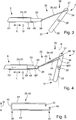
- the actuating element 31 is in a starting position I ( Figures 3 , 6th , 9 , 12th , 16 ).
- the actuating element 31 is in a working position W ( Figures 4 , 7th , 13th , 17th ).
- an operator can exert an actuating force FB on the first arm 33.
- the coupling member 36 is designed to be elastically deformable.
- the coupling member 36 is formed integrally and thus has no seam or joint. It can form a separate component from the actuating element 31 ( Figures 3-15 ) or alternatively be formed integrally with the actuating element 31.
- the coupling member 36 can additionally or alternatively be formed integrally with the connecting part 39 ( Figures 16 and 17 ).
- the coupling member 36 can also only be formed integrally either with the actuating element 31 or with the connecting part 39 and otherwise arranged or fastened as is shown or explained in the other exemplary embodiments.
- the coupling member 36 forms a connecting rod 42.
- the connecting rod 42 is designed to convert the pivoting movement of the second arm 34 into a linear movement in the longitudinal direction L of the tool 24 or the connecting part 39.
- the first end 37 is therefore arranged on the second arm 34 and therefore mounted so as to be pivotable about the pivot axis S or the pivot joint 32.
- the first The end 37 of the coupling member 36 is arranged at a distance from the pivot axis or from the pivot joint 32.
- the second end 38 of the coupling member 36 is arranged to be displaceable in the longitudinal direction L together with the tool 24 or the connecting part 39.
- the coupling member 36 can therefore also be referred to as a connecting rod 42.
- the coupling member 36 has a first longitudinal limb 43 and a second longitudinal limb 44.
- the two longitudinal legs 43, 44 are arranged at a distance from one another in the transverse direction Q.
- the two longitudinal legs 43, 44 are connected to one another via a transverse leg 45 extending in the transverse direction Q and, according to the example, are formed integrally.
- the first longitudinal limb 43 has a first free limb end 46 and the second longitudinal limb 44 has a second free limb end 47.
- the free leg ends 46, 47 are bent or angled with respect to the longitudinal legs 43, 44 and in the exemplary embodiment extend essentially parallel to the transverse leg 45, i.e. in the transverse direction Q.
- the first free leg end 46 and the second free leg end 47 are, for example, shorter than the transverse leg 45.
- the free leg ends 46, 47 are offset or arranged at a distance from one another in a projection plane which is aligned at right angles to the transverse direction Q.
- this is achieved in that the first longitudinal leg 43 extends from the transverse leg 45 to the
- the first free leg end 46 has a greater length than the second longitudinal leg 44 from the transverse leg 45 to the second free leg end 47.
- the transverse limb 45 can extend through a through hole in the transverse direction Q through the connecting part 39.
- the transverse limb 45 can also engage in a groove open at the top on the connecting part 39 and / or on the tool 24 and optionally be latched, so that a detachable connection is established between the tool 24 and the coupling device 35. This can simplify the assembly and / or replacement of the tool independently of the coupling device 35.
- the two free leg ends 46, 47 can each protrude into a receiving hole in the second arm 34.
- the coupling member 36 is rotatably or articulated both on the connecting part 39 and on the second arm 34.
- the coupling member 36 In the starting position I of the actuating element 31, the coupling member 36 assumes a first state. In the first state, the coupling member can be elastically undeformed. In the working position W of the actuating element 31, the coupling member 36 assumes a second state that is elastically deformed compared to the first state.
- the two longitudinal legs 43, 44 and the transverse leg 45 extend in a common plane ( Figure 3 ). If the actuating element 31 is pivoted out of its starting position I, the two longitudinal legs 43, 44 are viewed in a projection plane which is perpendicular to the transverse direction Q extends, inclined relative to each other. This is due to the fact that the bearing points of the two free leg ends 46, 47 outside the starting position I no longer lie together with the transverse leg 45 in one plane.
- the inclination of the two longitudinal limbs 43, 44 relative to one another outside of the starting position I leads to the transverse limb 45 being twisted and thereby generating a torsional moment MT in the circumferential direction around the transverse limb 45, which urges the two longitudinal limbs 43, 44 to return to their position to be taken in the common plane with the transverse leg 45.
- the two free leg ends 46, 46 in the working position W of the actuating element 31 are arranged on the same side with respect to a reference plane B extending at right angles to the longitudinal direction L and along the pivot axis of the actuating element 31 ( Figure 4 ).
- the two free leg ends 46, 46 are arranged in the working position W of the actuating element 31 on one side and the second end 38 of the coupling member 36 on the other side of the reference plane B.
- the coupling member 36 not only forms a mechanical element via which the movement coupling between the actuating element 31 and the tool 24 is established, but at the same time also a restoring device, whereby the actuating element 31 is pushed back into its starting position I. Without the application of an actuating force FB to the actuating element 31, it increases the starting position I and the tool 24 and, for example, the knife 25 is withdrawn into the retracted position E. Additional elastically deformable restoring elements, in particular helical springs, can be omitted.
- the construction of the coupling device 35 is very simple. The number of elements required in the coupling device 35 or the actuating device 30 is reduced. The simple structure also makes cleaning easier. In particular, by avoiding helical springs, in which the coils can lie close to one another, cleaning or sterilization is made much easier.
- the coupling member 36 also generates a force component in a direction perpendicular to the longitudinal direction L and perpendicular to the transverse direction Q, which is referred to as the pressing force FA.
- This force component arises when in the embodiment according to Figures 3 and 4 the transverse leg 45 is twisted, i.e. at least outside the initial position I.
- This pressing force FA can be used to press a latching projection 48 on the tool 24 and / or on the connecting part 39 into an associated latching recess 49 adjacent to the tool channel 23. It is also possible for several latching projections 48 and / or several latching recesses 49 to be present.
- the tool 24 can lock in at least one position during the movement in the longitudinal direction L.
- an operator can be given feedback on the currently reached position of the tool 24 relative to the tool channel 23 or relative to the branches 21, 22.
- the modified coupling member 36 is in particular shown in FIG Figure 8 to recognize.
- the coupling member 36 has a bow-shaped shape with a first longitudinal limb 43, a second longitudinal limb 44 and a transverse limb 45 at the second end 38.
- the opposite first end 37 of the coupling member 36 is configured differently than in the embodiment according to Figure 5 .
- Both longitudinal legs 43, 44 are preferably of equal length and the free leg ends 46, 47 extending in the transverse direction Q are preferably aligned along a common straight line in the transverse direction Q.
- Each longitudinal leg 43, 44 has a straight leg section 43a, 44a that extends in a straight line from the transverse leg 45 and a bent leg section 43b, 44b directly adjoining it.
- the curved leg section 43b, 44b has an arcuate and, in particular, circular arc shape in the rest state not acted upon by a force.
- the in Figure 8 illustrated embodiment, the curved leg portion 43b, 44b has at least one complete Winding and, according to the example, several windings.
- the wound or curved leg section 43b establishes a connection between the relevant straight leg section 43a, 44a and the respective leg end 46, 47.
- the coupling member 36 according to FIG Figure 8 is formed integrally and can be produced, for example, by bending a wire.
- the free leg ends 46, 47 are arranged closer to the transverse leg 45 than the wound or curved leg sections 43b, 44b.
- the transverse limb 45 passes through a through hole in the connecting part 39 or, alternatively, in the tool 24.
- the free limb ends 46, 47 each engage in a recess or depression on the second arm 34.
- FIG. 9-11 shows a further embodiment of the actuating device 30 which is similar to the embodiment according to FIG Figures 3-5 so that reference can be made to the description of these figures.
- the main difference in this exemplary embodiment is that there is only one longitudinal leg 43 which connects the transverse leg 45 at the second end 38 to the first end 37.
- the second longitudinal limb 44 extends from the transverse limb 45 only in the area of the second end 38 and serves there for the non-rotatable arrangement of the coupling member 36 on the tool 24 and, for example, on the connecting part 39 with respect to the transverse limb 45 be arranged on a through hole 53 for the transverse leg 45 adjoining groove 54.
- the transverse limb 45 remains twistable about a direction of extension when the first longitudinal limb 43 moves or pivots relative to the second longitudinal limb 44, which is arranged non-rotatably, by actuating the actuating element 31.
- the first end 37 of the coupling member 36 is fixed on the actuating element 31.
- the coupling member 36 can be bent several times at the first end 37, so that two holding legs 55 are formed which extend in the transverse direction Q and are connected to one another via a connecting leg 56.
- an intermediate space 57 is delimited, into which the second arm 34 can engage.
- the holding limbs 55 and the connecting limb 56 encompass, so to speak, the second arm 34 of the actuating element 31.
- a holding groove 58 can be present in the second arm 34, in which at least the retaining leg 55 and / or the connecting leg 56 is arranged.
- FIG 11 the force and torque loading of the coupling member 36 is illustrated in a highly schematic manner when the actuating element 31 is deflected from its starting position I.
- the pivoting of the two longitudinal legs 43, 44 relative to one another about the transverse leg 45 creates a torsional moment MT on the transverse leg 45.
- the first longitudinal limb 43 can be bent out of its straight extension.
- a restoring moment MR arises about the pivot axis S or the pivot joint 32, which pushes the actuating element 31 back into its starting position I.
- the one in the Figures 12 and 13 illustrated embodiment of the actuating device 30 corresponds to the structure of the previously described embodiments apart from the design of the coupling member 36.
- the coupling member 36 is designed in this embodiment so that it is bent from its original extension in the initial position I of the actuating element 31 and thereby the restoring torque MR causes.
- the coupling member 36 can have the shape of a leaf spring, as shown schematically in FIG Figure 14 is illustrated.
- the coupling member 36 is fixed at the first end 37 and the second arm 34 and at the second end 38 on the tool 24 or on the connecting part 39 in the orientation that it assumes in the starting position I.
- a bend in the coupling member 36 is produced.
- the coupling member 36 tries to assume its original position again and in this way generates the restoring torque MR.
- the coupling member 36 can have at least one opening and / or at least one outwardly open recess at the first end 37 or at the second end 38.
- the parts delimiting the recess can be arranged in grooves or recesses, for example on the second arm 34.
- the coupling member 36 can be overmolded with the material of the connecting part 39, for example at the second end 38.
- the connection at the first end 37 and at the second end 38 can be positive and / or non-positive and / or cohesive and / or an adhesive connection.
- the coupling member 36 can preferably be overmolded at least at one of the two ends 37 or 38 or alternatively also at both ends 37 and 38.
- the coupling member 36 can also be formed by a wire element or wire bracket element ( Figure 15 ). It essentially consists of a longitudinal limb 43 which extends between the first end 37 and the second end 38 and which merges into an end limb 59 extending at right angles to the longitudinal limb 43 both at the first end 37 and at the second end 38.
- the two end legs 59 preferably extend parallel to one another and in particular in a plane that is spanned at right angles to the transverse direction.
- the two end legs 59 can be inserted into corresponding holes or recesses on the second arm 34 or on the tool 24 or connecting part 39 and there, if necessary be fixed, for example by an adhesive connection.
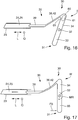
- FIGS Figures 16 and 17 Another embodiment of the actuator 30 is shown in FIGS Figures 16 and 17 illustrated. While the coupling member 36 was a separate component in the embodiments described above, the coupling member 36 in the embodiment according to FIG Figures 16 and 17 formed integrally with the actuating element 31 and / or integrally with the connecting part 39. In the embodiment shown, the actuating element 31, the coupling member 36 and the connecting part 39 are a single integral component, which consists for example of plastic and can in particular be designed as an injection-molded part.
- the coupling member 36 is formed integrally only with the actuating element 31 or only with the connecting part 39, it can be non-positively and / or positively and / or cohesively and / or by means of adhesion with the actuating element 31 or with at the respective other end 37 or 38 be connected to the connecting part 39.
- the coupling member 36 forms analogously to the exemplary embodiments according to FIG Figures 12-15 a spiral spring and can thus take the form of a leaf spring similar to the embodiment according to Figure 14 or a web-like shape similar to the straight longitudinal leg 43 according to FIG Figure 15 exhibit.
- the mode of operation corresponds to that of the exemplary embodiment according to the Figures 12 and 13 .
- the restoring torque MR can also be generated at least partially by a deformation of the second arm 34 of the actuating element 31.
- the second arm 34 can have a corresponding deformable configuration. In Figure 16 this is exemplified by an opening 60 which penetrates the second arm. Adjacent to the opening 60, the second arm 34 has web-shaped sections 61 which are sufficiently small in cross-section. This enables the web-shaped sections 61 to be bent or deformed and / or the web-shaped sections to move towards one another. If this region of the second arm 34 is deformed (outside the initial position I), then the second arm 34 tends to assume its undeformed initial shape and thereby generates at least one component of the restoring torque MR.
- the coupling member 36 can be formed by a bent wire part.
- the wire can have a circular cross-section.
- a releasable connection between the tool 24 and the coupling device 35 can be established indirectly via the connecting part 39 or also directly, for example a non-positive and / or positive connection, preferably a latching connection.
- the invention relates to an actuating device 30 for actuating a tool 24 of a surgical instrument 20.
- the actuating device 30 has an actuating element 31 which is pivotably mounted between an initial position I and a working position W.
- a coupling device 35 which has a coupling member 36 or is formed by the coupling member 36, the actuating element 31 is coupled in terms of movement to the tool 24.
- the coupling member 36 is elastically deformable and, when the actuating element 31 is deflected from the initial position I, the elastic deformation causes a restoring torque MR which pushes the actuating element 31 back into the initial position I. Additional resilient return elements can therefore be omitted.
Landscapes
- Health & Medical Sciences (AREA)
- Surgery (AREA)
- Life Sciences & Earth Sciences (AREA)
- Engineering & Computer Science (AREA)
- Molecular Biology (AREA)
- Public Health (AREA)
- Heart & Thoracic Surgery (AREA)
- Medical Informatics (AREA)
- Nuclear Medicine, Radiotherapy & Molecular Imaging (AREA)
- Animal Behavior & Ethology (AREA)
- General Health & Medical Sciences (AREA)
- Biomedical Technology (AREA)
- Veterinary Medicine (AREA)
- Otolaryngology (AREA)
- Physics & Mathematics (AREA)
- Plasma & Fusion (AREA)
- Ophthalmology & Optometry (AREA)
- Surgical Instruments (AREA)
Abstract
Description
- Die Erfindung betrifft ein chirurgisches Instrument, beispielsweise ein elektrochirurgisches Instrument. Das chirurgische Instrument kann zwei schwenkbar aneinander gelagerte Branchen aufweisen. An dem chirurgischen Instrument ist ein in einer Längsrichtung geführt bewegbar gelagertes Werkzeug vorhanden, z.B. ein Messer. Das Messer kann in einem Messerkanal gelagert sein. Über ein Betätigungselement kann das Messer in Längsrichtung bewegt werden, beispielsweise um zwischen den Branchen eingeklemmtes biologisches Gewebe zu durchtrennen.
-
EP 2 436 327 A1 beschreibt eine chirurgische Klemme mit zwei schwenkbar aneinander gelagerten Branchen und einem in einer Längsrichtung geführten Messer. Über ein schwenkbar gelagertes Betätigungselement kann das Messer in Längsrichtung bewegt werden. Um das Betätigungselement in eine Ausgangsstellung vorzuspannen, ist eine Schraubenfeder vorhanden, die beim Auslenken des Betätigungselements aus seiner Ausgangslage auf Zug beansprucht wird und ein Rückstellmoment in Richtung der Ausgangslage erzeugt. -
US 2017/0209205 A1 beschreibt eine bipolare chirurgische Klemme mit zwei schwenkbar aneinander gelagerten Branchen und einem in einer Längsrichtung geführt gelagerten Messer. Über ein Betätigungselement kann das Messer in Längsrichtung bewegt werden. Das Betätigungselement ist über eine Kopplungseinrichtung mit dem Messer bewegungsgekoppelt, wobei die Kopplungseinrichtung einen Teleskophebel aufweist, um beim Schwenken des Betätigungselements um eine Schwenkachse den benötigten Raum für die Schwenkbewegung gering halten zu können. Beim Schwenken des Betätigungselements von einer Ausgangslage in eine Arbeitslage wird der Teleskophebel beim Kontakt mit einer Gehäusewand zunächst eingefahren und anschließend wieder ausgefahren. Dadurch soll das Gehäuse klein gehalten werden können. Zusätzlich ist ein nicht dargestelltes Vorspannelement vorhanden, das einerseits am Teleskophebel und andererseits am Betätigungselement angreift, um das Betätigungselement in seiner Ausgangsstellung vorzuspannen. - Die bislang bekannten Anordnungen sind konstruktiv aufwendig, was insbesondere bei Einweginstrumenten zu hohen Kosten führt. Bei Mehrweginstrumenten ist das Reinigen und Sterilisieren problematisch, insbesondere wenn Schraubenfedern oder teleskopierbare Anordnungen eingesetzt werden. Dort können Verschmutzungen nicht oder nur mit großem Aufwand entfernt werden.
- Es kann daher als Aufgabe der vorliegenden Erfindung angesehen werden, ein chirurgisches Instrument zu schaffen, das einen kostengünstigen Aufbau und eine einfache Reinigung gewährleistet.
- Diese Aufgabe wird durch ein chirurgisches Instrument mit den Merkmalen des Patentanspruches 1 gelöst.
- Das erfindungsgemäße chirurgische Instrument weist ein Werkzeug auf, beispielsweise ein Messer, das in einer Längsrichtung bewegbar angeordnet ist. Zur Betätigung des Werkzeugs ist ein Betätigungselement vorhanden. Das Betätigungselement ist schwenkbar gelagert. Es kann zwischen einer Ausgangslage und einer Arbeitslage geschwenkt werden.
- Über eine Kopplungseinrichtung wird eine Bewegungskopplung zwischen dem Betätigungselement und dem Werkzeug hergestellt. Die Kopplungseinrichtung weist ein Kopplungsglied auf. Das Kopplungsglied ist dazu eingerichtet, die Schwenkbewegung des Betätigungselements auf das Werkzeug und/oder ein mit dem Werkzeug insbesondere unbeweglich verbundenes Teil zu übertragen. Das Kopplungsglied bildet bei einer bevorzugten Ausführungsform ein Pleuel der Kopplungseinrichtung. Das vorzugsweise vom Kopplungsglied gebildete Pleuel ist an einem Ende gelagert, um eine Drehbewegung oder Schwenkbewegung auszuführen und am anderen Ende gelagert, um eine im Wesentlichen geradlinige Bewegung in Längsrichtung auszuführen.
- Das Kopplungsglied ist elastisch verformbar. Vorzugsweise ist das Kopplungsglied in der Ausgangslage des Betätigungselements elastisch nicht verformt oder elastisch weniger stark verformt als in der Arbeitslage des Betätigungselements und nimmt einen ersten Zustand ein. In der Arbeitslage des Betätigungselements ist das Kopplungsglied elastisch stärker verformt als in seinem ersten Zustand und bewirkt ein Rückstellmoment auf das schwenkbar gelagerte Betätigungselement in Richtung der Ausgangslage. Der Zustand des elastisch verformten Kopplungsglied in der Arbeitslage des Betätigungselements wird als zweiter Zustand bezeichnet.
- Erfindungsgemäß bewirkt somit das Kopplungsglied selbst das Rückstellmoment auf das Betätigungselement, um dieses in die Ausgangslage zurückzubewegen. Auf zusätzliche Elemente zur Erzeugung des Rückstellmoments und insbesondere auf Schraubenfedern kann verzichtet werden.
- Es ist vorteilhaft, wenn die Kopplungseinrichtung und beispielsweise das Kopplungsglied lösbar mit dem Werkzeug verbunden ist. Diese lösbare Verbindung kann insbesondere kraftschlüssig und/oder formschlüssig sein und beispielsweise durch eine Rastverbindung realisiert werden. Dadurch kann das Werkzeug ausgetauscht werden und die Kopplungseinrichtung bzw. das Kopplungsglied kann im Instrument verbleiben. Alternativ oder zusätzlich kann eine solche lösbare Verbindung auch an einer anderen Stelle der Kopplungseinrichtung vorhanden sein, beispielsweise an der Verbindung zwischen der Kopplungseinrichtung und dem Betätigungselement.
- Die lösbare Verbindung kann bei einem Ausführungsbeispiel durch eine Nut im Werkzeug realisiert werden, in die die Kopplungseinrichtung bzw. das Kopplungsglied eingreift. Durch eine elastische Verformungskraft im ersten Zustand des Kopplungsgliedes wird zumindest eine kraftschlüssige Verbindung bewirkt.
- Vorzugsweise nimmt das Werkzeug in der Ausgangslage des Betätigungselements eine eingefahrene Stellung ein. In der Arbeitslage des Betätigungselements kann das Werkzeug eine ausgefahrene Stellung einnehmen. In einer eingefahrenen Stellung ist das Werkzeug ohne Einfluss auf biologisches Gewebe. In einer ausgefahrenen Stellung kann das Werkzeug auf biologisches Gewebe einwirken.
- Das chirurgische Instrument kann vorzugsweise zwei schwenkbar aneinander gelagerte Branchen aufweisen. Das Werkzeug ist in einer der Branchen in Längsrichtung bewegbar gelagert, beispielsweise in einem Werkzeugkanal.
- Das Werkzeug kann ein Messer sein, wobei der Werkzeugkanal einen Messerkanal bildet. Beispielsweise kann ein Messer in der ausgefahrenen Stellung biologisches Gewebe schneiden.
- Bevorzugt verbindet das Kopplungsglied, beispielsweise das Pleuel, zwei mit Abstand zueinander angeordnete Teile. Diese Teile können vom Betätigungselement oder einem damit bewegungsgekoppelten Teil einerseits und vom Werkzeug oder einem damit bewegungsgekoppelten Verbindungsteil andererseits gebildet werden. Ohne das Kopplungsglied wäre die Bewegungsübertragung vom Betätigungselement auf das Werkzeug nicht möglich.
- Das Kopplungsglied ist insbesondere integral einstückig ausgebildet. Es ist aus einem elastisch verformbaren Material hergestellt, beispielsweise aus einem metallischen Material, insbesondere einer metallischen Legierung. Optional kann es mit einer Schutzschicht versehen sein, um das Kopplungsglied gegen chemische Einwirkungen zu schützen, wobei die Schutzschicht für die Bewegungskopplung keine Bedeutung hat.
- Bei einer bevorzugten Ausführungsform ist das Kopplungsglied mit einem Ende unmittelbar am Betätigungselement mit Abstand zur Schwenkachse des Betätigungselements angebracht. Mit dem jeweils anderen Ende kann das Kopplungsglied unmittelbar mit dem Werkzeug oder einem mit dem bewegungsgekoppelten Verbindungsteil angeordnet sein. Insbesondere ist das Verbindungsteil unbeweglich am Werkzeug angeordnet. Das Kopplungsglied kann dazu eingerichtet sein, eine Schwenkbewegung des Betätigungselements in eine lineare Bewegung des Werkzeugs zu übersetzen. Das Kopplungsglied kann das einzige Teil sein, das für die Übersetzung der Schwenkbewegung in die lineare Bewegung vorhanden ist.
- Es ist vorteilhaft, wenn das Kopplungsglied eine bügelförmige Gestalt hat. Es kann beispielsweise als Drahtbügel oder Stanzbügel ausgebildet sein. Insbesondere kann das Kopplungsglied wenigstens einen Längsschenkel und einen sich daran anschließenden Querschenkel aufweisen. Der Querschenkel erstreckt sich insbesondere rechtwinklig zur Bewegungsrichtung des Werkzeugs, also rechtwinklig zur Längsrichtung. Der wenigstens eine Längsschenkel erstreckt sich vorzugsweise unter einem Winkel geneigt zur Längsrichtung, der einen Betrag zwischen 0 Grad und 90 Grad aufweist, vorzugsweise zwischen 10 Grad und 80 Grad und weiter vorzugsweise zwischen 20 Grad und 70 Grad.
- Es ist insbesondere vorteilhaft, wenn das Kopplungsglied zwei und insbesondere genau zwei Längsschenkel aufweist, die über den Querschenkel miteinander verbunden sind. Der Querschenkel bildet vorzugsweise ein Ende des Kopplungsgliedes und insbesondere das Ende, das dem Werkzeug zugeordnet ist.
- Jeder Längsschenkel kann ein freies Schenkelende aufweisen, die vorzugsweise nicht unmittelbar miteinander verbunden sind und weiter vorzugsweise nicht unmittelbar aneinander anliegen. Insbesondere sind die freien Schenkelenden der Längsschenkel in einer Ebene, die rechtwinklig zur Querrichtung ausgerichtet ist, versetzt zueinander angeordnet. Insbesondere sind die freien Schenkelenden innerhalb dieser Ebene entlang einer gemeinsamen Geraden in Erstreckungsrichtung der Längsschenkel angeordnet, wenn sich das Kopplungsglied in einem unverformten Ruhezustand befindet, der beispielsweise dem ersten Zustand entsprechen kann.
- Die Längsschenkel des Kopplungsgliedes können unterschiedlich lang sein.
- Es ist bevorzugt, wenn sich die Längsschenkel und der Querschenkel in der Ausgangslage des Betätigungselements in einer gemeinsamen Ebene erstrecken. Außerhalb der Ausgangslage und insbesondere in der Arbeitslage des Betätigungselements können die Längsschenkel einen Winkel größer als Null einschließen. Der eingeschlossene Winkel zwischen den Längsschenkeln ist in der Arbeitslage am größten und nimmt zur Ausgangslage hin ab, wobei er in der Ausgangslage vorzugsweise gleich Null ist.
- Es ist insbesondere vorteilhaft, wenn die Längsschenkel im zweiten Zustand des Kopplungsgliedes (Arbeitslage des Betätigungselements) elastisch unverformt sind verglichen mit dem ersten Zustand des Kopplungsgliedes (Ausgangslage des Betätigungselements). Wenn sich die Längsschenkel im ersten Zustand des Kopplungsgliedes beispielsweise geradlinig erstrecken, erstrecken sie sich im zweiten Zustand des Kopplungsgliedes bevorzugt ebenfalls im Wesentlichen geradlinig. Die Längsschenkel können also insbesondere biegesteif gegenüber einer Biegung quer zu ihrer Erstreckungsrichtung sein. Bei dieser Ausgestaltung kann eine in Längsrichtung auf das Werkzeug von außen einwirkende Kraft sehr gut über das Kopplungsglied am Betätigungselement abgestützt werden. Das Werkzeug wird somit nicht unerwünscht aus seiner ausgefahrenen Stellung in die eingefahrene Stellung zurückgedrängt. Dieser Abstützeffekt ist insbesondere dann verbessert, wenn die Längsschenkel in der Arbeitslage einen Winkel größer als Null einschließen. Der Winkel zwischen den Längsschenkeln wird in einer Projektionsebene gemessen, die rechtwinklig zur Querrichtung und somit rechtwinklig zum Querschenkel ausgerichtet ist.
- Sollten sich die Längsschenkel im ersten Zustand des Kopplungsgliedes gekrümmt und/oder abgewinkelt und/oder abgeknickt erstrecken, kann diese Form im zweiten Zustand des Kopplungsgliedes aufrechterhalten bleiben.
- Unabhängig von der Anzahl der Längsschenkel ist der Querschenkel im zweiten Zustand des Kopplungsgliedes (Arbeitslage des Betätigungselements) vorzugsweise um seine Erstreckungsrichtung tordiert. Diese Torsion erzeugt ein Drehmoment auf den wenigstens einen mit dem Querschenkel verbundenen Längsschenkel, wodurch das Rückstellmoment bewirkt wird.
- Es ist vorteilhaft, wenn sich das Kopplungsglied im ersten Zustand geradlinig oder weniger stark gekrümmt zwischen seinen beiden Enden erstreckt als im zweiten Zustand. Zumindest im zweiten Zustand kann sich das Kopplungsglied gekrümmt zwischen seinen beiden Enden erstrecken. Bei dieser Ausführungsform kann das Kopplungsglied eine bügelförmige Gestalt aufweisen oder nach Art einer Blattfeder als flächiges Element ausgebildet sein. Das Kopplungsglied kann bei dieser Ausführungsform an einem Ende oder an beiden Enden drehfest befestigt sein, insbesondere an einem Ende drehfest mit dem Betätigungselement und/oder am anderen Ende drehfest mit dem Werkzeug oder einem mit dem Werkzeug insbesondere unbeweglich verbundenen Verbindungsteil.
- Bei einem Ausführungsbeispiel kann das zumindest außerhalb seines ersten Zustandes elastisch verformte Kopplungsglied eine Kraft oder Kraftkomponente rechtwinklig zur Längsrichtung und insbesondere auch rechtwinklig zur Querrichtung auf das Werkzeug oder ein mit dem Werkzeug verbundenes Verbindungsteil ausüben. Auf diese Weise ist es beispielsweise möglich, das Werkzeug oder das Verbindungsteil in wenigstens einer vorgegebenen Position in Längsrichtung zu einzurasten.
- Vorteilhafte Ausgestaltungen des erfindungsgemäßen chirurgischen Instruments ergeben sich aus den abhängigen Patentansprüchen, der Beschreibung und den Zeichnungen. Nachfolgend werden bevorzugte Ausführungsbeispiele anhand der beigefügten Zeichnungen im Einzelnen erläutert. Die Figuren der Zeichnungen zeigen:
-
Figuren 1 und 2 jeweils eine schematische Seitenansicht eines chirurgischen Instruments, insbesondere eines elektrochirurgischen Instruments, -
Figur 3 ein Ausführungsbeispiel einer Betätigungsvorrichtung des chirurgischen Instruments in einer schematischen Seitenansicht, wobei sich ein Betätigungselement der Betätigungsvorrichtung in einer Ausgangslage befindet und ein Kopplungsglied einer Kopplungseinrichtung einen ersten Zustand einnimmt, -
Figur 4 die Betätigungsvorrichtung ausFigur 3 in einer schematischen Seitenansicht, wobei sich das Betätigungselement in einer Arbeitslage befindet und ein Kopplungsglied einer Kopplungseinrichtung einen zweiten Zustand einnimmt, -
Figur 5 ein Ausführungsbeispiel eines Kopplungsgliedes der Betätigungsvorrichtung aus denFiguren 3 und 4 in einer Draufsicht, -
Figur 6 ein weiteres Ausführungsbeispiel einer Betätigungsvorrichtung für das chirurgische Instrument in einer schematischen Seitenansicht, wobei sich ein Betätigungselement der Betätigungsvorrichtung in einer Ausgangslage befindet und ein Kopplungsglied einer Kopplungseinrichtung einen ersten Zustand einnimmt, -
Figur 7 das Ausführungsbeispiel der Betätigungsvorrichtung ausFigur 6 in einer schematischen Seitenansicht, wobei sich das Betätigungselement in einer Arbeitslage befindet und ein Kopplungsglied einer Kopplungseinrichtung einen zweiten Zustand einnimmt, -
Figur 8 eine perspektivische Darstellung eines Ausführungsbeispiels eines Kopplungsgliedes der Betätigungsvorrichtung gemäß derFiguren 6 und 7 , -
Figur 9 ein weiteres Ausführungsbeispiel einer Betätigungsvorrichtung für das chirurgische Instrument in einer schematischen Seitenansicht, wobei sich ein Betätigungselement der Betätigungsvorrichtung in einer Ausgangslage befindet und ein Kopplungsglied einer Kopplungseinrichtung einen ersten Zustand einnimmt, -
Figur 10 das Betätigungselement, ein Kopplungsglied und ein Verbindungsteil der Betätigungsvorrichtung ausFigur 9 in schematischer Einzeldarstellung, -
Figur 11 das Kopplungsglied der Betätigungsvorrichtung gemäß derFiguren 9 und 10 in einer schematischen Seitenansicht, wobei das Kopplungsglied elastisch verformt ist und seinen zweiten Zustand einnimmt, -
Figur 12 ein weiteres Ausführungsbeispiel einer Betätigungsvorrichtung für das chirurgische Instrument in einer schematischen Seitenansicht, wobei sich ein Betätigungselement der Betätigungsvorrichtung in einer Ausgangslage befindet und ein Kopplungsglied einer Kopplungseinrichtung einen ersten Zustand einnimmt, -
Figur 13 das Ausführungsbeispiel der Betätigungsvorrichtung ausFigur 12 in einer schematischen Seitenansicht, wobei sich das Betätigungselement in einer Arbeitslage befindet und ein Kopplungsglied einer Kopplungseinrichtung einen zweiten Zustand einnimmt, -
Figuren 14 und 15 jeweils eine schematische Prinzipdarstellung eines Kopplungsgliedes der Betätigungsvorrichtung gemäß derFiguren 12 und 13 in einer Draufsicht, -
Figur 16 ein weiteres Ausführungsbeispiel einer Betätigungsvorrichtung für das chirurgische Instrument in einer schematischen Seitenansicht, wobei sich ein Betätigungselement der Betätigungsvorrichtung in einer Ausgangslage befindet und ein Kopplungsglied einer Kopplungseinrichtung einen ersten Zustand einnimmt und -
Figur 17 das Ausführungsbeispiel der Betätigungsvorrichtung ausFigur 16 in einer schematischen Seitenansicht, wobei sich das Betätigungselement in einer Arbeitslage befindet und ein Kopplungsglied einer Kopplungseinrichtung einen zweiten Zustand einnimmt. - In den
Figuren 1 und 2 sind schematisiert unterschiedliche Ausführungsbeispiele eines chirurgischen Instruments 20 veranschaulicht. Das chirurgische Instrument 20 kann, wie dargestellt, als elektrochirurgisches Instrument ausgebildet sein. Es kann sich um ein monopolares oder ein bipolares elektrochirurgisches Instrument handeln. Das chirurgische Instrument ist insbesondere als Mehrweginstrument ausgebildet. Es muss daher nach jeder Benutzung gereinigt und sterilisiert werden. - Das chirurgische Instrument 20 hat bei den veranschaulichten Ausführungsbeispielen zwei schwenkbar aneinander gelagerte Branchen 21, 22. Jede Branche 21, 22 hat eine Gewebekontaktfläche 21a bzw. 22a. Die Branchen 21, 22 können aufeinander zu oder voneinander weg bewegt werden, um ein biologisches Gewebe zwischen den Gewebekontaktflächen 21a, 22a einzuklemmen oder loszulassen.
- Das chirurgische Instrument 20 weist außerdem ein Werkzeug 24 auf. Das Werkzeug 24 ist in einer Längsrichtung L bewegbar in einem Werkzeugkanal 23 gelagert. Das Werkzeug 24 kann beispielsweise durch ein Messer 25 gebildet sein. Der Werkzeugkanal 23 kann sich innerhalb eines sich an die Branchen 21, 22 anschließenden Schaftes 26 erstrecken (
Figur 1 ) und/oder innerhalb einer der Branchen 21, 22 verlaufen (Figur 2 ). - Das Instrument 20 weist eine Bedieneinheit 27 auf. Mittels der Bedieneinheit 27 können die Branchen 21, 22 gegeneinander verschwenkt und das Werkzeug 24 in Längsrichtung L bewegt werden. Bei elektrochirurgischen Instrumenten kann mittels der Bedieneinheit 27 außerdem eine elektrische Spannung an die Gewebekontaktflächen 21a, 22a angelegt werden.
- Das Werkzeug 24 und beispielsgemäß das Messer 25 kann zwischen einer eingefahrenen Stellung E und einer ausgefahrenen Stellung A in Längsrichtung L bewegt werden. Dazu weist das Instrument 20 eine Betätigungsvorrichtung 30 auf. In den
Figuren 3-17 sind unterschiedliche Ausführungsformen der Betätigungsvorrichtung 30 oder Bestandteilen davon schematisch veranschaulicht. - Die Betätigungsvorrichtung 30 weist ein Betätigungselement 31 auf, das Bestandteil der Bedieneinheit 27 zur Bedienung des Instruments 20 ist. Das Betätigungselement 31 kann als separates Bedienelement der Bedieneinheit 27 ausgebildet sein (
Figur 2 ) oder alternativ durch ein Bedienelement gebildet sein, das auch eine oder mehrere weitere Funktionen aufweist (Figur 1 ). - Das Betätigungselement 31 ist schwenkbar um eine Schwenkachse gelagert. Die Schwenkachse erstreckt sich beim Ausführungsbeispiel in einer Querrichtung Q, die rechtwinklig zur Längsrichtung L ausgerichtet ist. Die Schwenkachse ist durch ein Schwenkgelenk 32 definiert, mittels dem das Betätigungselement 31 schwenkbar an einem ortsfest bzw. unbeweglich gegenüber dem Gehäuse des Instruments 20 angeordneten Teil gelagert ist. Das Betätigungselement 31 hat zwei sich ausgehend vom Schwenkgelenk 32 erstreckende Arme 33, 34. Die Arme 33, 34 können sich in unterschiedliche und insbesondere entgegengesetzte Richtungen erstrecken, wie es beim Ausführungsbeispiel gezeigt ist.
- Ein erster Arm 33 dient zur manuellen Betätigung. Ein zweiter Arm 34 ist über eine Kopplungseinrichtung 35 mit dem Werkzeug 24 bewegungsgekoppelt.
- Die Kopplungseinrichtung 35 weist ein elastisch verformbares Kopplungsglied 36 auf. Beim Ausführungsbeispiel ist die Kopplungseinrichtung 35 durch das Kopplungsglied 36 gebildet. Zusätzliche bewegungsübertragende Bauteile können entfallen. Das Kopplungsglied 36 ist beispielsgemäß mit einem ersten Ende 37 am Betätigungselement 31 und insbesondere dem zweiten Arm 34 angeordnet. Vom ersten Ende 37 erstreckt sich das Kopplungsglied 36 zu einem zweiten Ende 38, das dem Werkzeug 24 oder einem mit dem Werkzeug 24 vorzugsweise unbeweglich verbundenen Verbindungsteil 39 zugeordnet ist. Bei den hier veranschaulichten Ausführungsbeispielen ist das zweite Ende 38 am Verbindungsteil 39 angeordnet. In Abwandlung hierzu könnte es auch unmittelbar am Werkzeug 24 angeordnet sein.
- Durch die Bewegungskopplung zwischen dem Werkzeug 24 und dem Betätigungselement 31 mittels der Kopplungseinrichtung 35 kann das Schwenken des Betätigungselements 31 um die Schwenkachse bzw. das Schwenkgelenk 32 in eine Bewegung des Werkzeugs 24 in Längsrichtung L übersetzt werden, insbesondere um das Werkzeug 24 zwischen der eingefahrenen Stellung E und der ausgefahrenen Stellung A zu bewegen. Wenn sich das Werkzeug 24 in der eingefahrenen Stellung E befindet, befindet sich das Betätigungselement 31 in einer Ausgangslage I (
Figuren 3 ,6 ,9 ,12 ,16 ). Wenn das Werkzeug 24 die ausgefahrene Stellung A einnimmt, befindet sich das Betätigungselement 31 in einer Arbeitslage W (Figuren 4 ,7 ,13 ,17 ). - Um das Betätigungselement 31 aus der Ausgangslage I in die Arbeitslage W zu schwenken, kann eine Bedienperson auf den ersten Arm 33 eine Betätigungskraft FB ausüben.
- Das Kopplungsglied 36 ist erfindungsgemäß elastisch verformbar ausgebildet. Das Kopplungsglied 36 ist bei den hier beschriebenen bevorzugten Ausführungsbeispielen integral ausgebildet und weist somit keine Naht- oder Fügestelle auf. Es kann gegenüber dem Betätigungselement 31 ein separates Bauteil bilden (
Figuren 3-15 ) oder alternativ integral mit dem Betätigungselement 31 ausgebildet sein. Das Kopplungsglied 36 kann zusätzlich oder alternativ integral mit dem Verbindungsteil 39 ausgebildet sein (Figuren 16 und 17 ). In Abwandlung zu dem in denFiguren 16 und 17 veranschaulichten Ausführungsbeispiel kann das Kopplungsglied 36 auch lediglich entweder mit dem Betätigungselement 31 oder mit dem Verbindungsteil 39 integral ausgebildet sein und ansonsten so angeordnet bzw. befestigt sein, wie es bei den anderen Ausführungsbeispielen dargestellt bzw. erläutert ist. - Bei den hier beschriebenen bevorzugten Ausführungsbeispielen bildet das Kopplungsglied 36 ein Pleuel 42. Das Pleuel 42 ist dazu eingerichtet, die Schwenkbewegung des zweiten Arms 34 in eine lineare Bewegung in Längsrichtung L des Werkzeugs 24 bzw. des Verbindungsteils 39 zu überführen. Beispielsgemäß ist das erste Ende 37 daher am zweiten Arm 34 angeordnet und mithin um die Schwenkachse S bzw. das Schwenkgelenk 32 schwenkbar gelagert. Das erste Ende 37 des Kopplungsgliedes 36 ist mit Abstand zur Schwenkachse bzw. zum Schwenkgelenk 32 angeordnet. Das zweite Ende 38 des Kopplungsgliedes 36 ist in Längsrichtung L gemeinsam mit dem Werkzeug 24 bzw. dem Verbindungsteil 39 verschiebbar angeordnet. Daher kann das Kopplungsglied 36 auch als Pleuel 42 bezeichnet werden.
- Bei dem in den
Figuren 3-5 veranschaulichten Ausführungsbeispiel der Betätigungsvorrichtung 30 weist das Kopplungsglied 36 einen ersten Längsschenkel 43 und einen zweiten Längsschenkel 44 auf. Die beiden Längsschenkel 43, 44 sind in Querrichtung Q mit Abstand zueinander angeordnet. Am zweiten Ende 38 sind die beiden Längsschenkel 43, 44 über einen sich in Querrichtung Q erstreckenden Querschenkel 45 miteinander verbunden und beispielsgemäß integral ausgebildet. - Am ersten Ende 37 weist der erste Längsschenkel 43 ein erstes freies Schenkelende 46 und der zweite Längsschenkel 44 ein zweites freies Schenkelende 47 auf. Die freien Schenkelenden 46, 47 sind gegenüber den Längsschenkeln 43, 44 umgebogen oder abgewinkelt und erstrecken sich beim Ausführungsbeispiel im Wesentlichen parallel zum Querschenkel 45, also in Querrichtung Q. Das erste freie Schenkelende 46 und das zweite freie Schenkelende 47 sind beispielsgemäß kürzer als der Querschenkel 45.
- Wie es insbesondere in den
Figuren 4 und 5 zu erkennen ist, sind die freien Schenkelenden 46, 47 in einer Projektionsebene, die rechtwinklig zur Querrichtung Q ausgerichtet ist, versetzt bzw. mit Abstand zueinander angeordnet. Dies ist beim Ausführungsbeispiel dadurch erreicht, dass der erste Längsschenkel 43 vom Querschenkel 45 bis zum ersten freien Schenkelende 46 eine größere Länge aufweist als der zweite Längsschenkel 44 vom Querschenkel 45 bis zum zweiten freien Schenkelende 47. - Der Querschenkel 45 kann sich durch ein Durchgangsloch in Querrichtung Q durch das Verbindungsteil 39 erstrecken. Alternativ dazu kann der Querschenkel 45 auch in eine oben offene Nut am Verbindungsteil 39 und/oder am Werkzeug 24 eingreifen und optional eingerastet werden, so dass eine lösbare Verbindung zwischen dem Werkzeug 24 und der Kopplungseinrichtung 35 hergestellt ist. Das kann die Montage und/oder den Austausch des Werkzeugs unabhängig von der Kopplungseinrichtung 35 vereinfachen.
- Die beiden freien Schenkelenden 46, 47 können jeweils in ein Aufnahmeloch im zweiten Arm 34 hineinragen. Beispielsgemäß ist das Kopplungsglied 36 drehbar bzw. gelenkig sowohl am Verbindungsteil 39, als auch am zweiten Arm 34 gelagert.
- In der Ausgangslage I des Betätigungselements 31 nimmt das Kopplungsglied 36 einen ersten Zustand ein. Im ersten Zustand kann das Kopplungsglied elastisch unverformt sein. In der Arbeitslage W des Betätigungselements 31 nimmt das Kopplungsglied 36 einen gegenüber dem ersten Zustand elastisch verformten zweiten Zustand ein.
- Im ersten Zustand des Kopplungsgliedes 36 erstrecken sich die beiden Längsschenkel 43, 44 und der Querschenkel 45 in einer gemeinsamen Ebene (
Figur 3 ). Wird das Betätigungselement 31 aus seiner Ausgangslage I heraus geschwenkt werden die beiden Längsschenkel 43, 44 in einer Projektionsebene betrachtet, die sich rechtwinklig zur Querrichtung Q erstreckt, relativ zueinander geneigt. Dies ist darauf zurückzuführen, dass die Lagerstellen der beiden freien Schenkelenden 46, 47 außerhalb der Ausgangslage I nicht mehr gemeinsam mit dem Querschenkel 45 in einer Ebene liegen. Das Neigen der beiden Längsschenkel 43, 44 relativ zueinander außerhalb der Ausgangslage I führt dazu, dass der Querschenkel 45 tordiert wird und dadurch ein Torsionsmoment MT in Umfangsrichtung um den Querschenkel 45 erzeugt wird, das die beiden Längsschenkel 43, 44 dazu drängt, wieder die Position in der gemeinsamen Ebene mit dem Querschenkel 45 einzunehmen. Dadurch wird gleichzeitig ein Rückstellmoment MR auf das Betätigungselement 31 bewirkt, das das Betätigungselement 31 zurück in seine Ausgangslage I drängt. - Beispielsgemäß sind die beiden freien Schenkelenden 46, 46 in der Arbeitslage W des Betätigungselements 31 auf derselben Seite bezüglich einer sich rechtwinkelig zur Längsrichtung L und entlang der Schwenkachse des Betätigungselements 31 erstreckenden Bezugsebene B angeordnet (
Figur 4 ). Insbesondere sind die beiden freien Schenkelenden 46, 46 in der Arbeitslage W des Betätigungselements 31 auf der einen Seite und das zweite Ende 38 des Kopplungsgliedes 36 auf der anderen Seite der Bezugsebene B angeordnet. - Somit bildet das Kopplungsglied 36 nicht nur ein mechanisches Element, über das die Bewegungskopplung zwischen dem Betätigungselement 31 und dem Werkzeug 24 hergestellt wird, sondern gleichzeitig auch eine Rückstelleinrichtung, wodurch das Betätigungselement 31 zurück in seine Ausgangslage I gedrängt wird. Ohne das Aufbringen einer Betätigungskraft FB auf das Betätigungselement 31 nimmt es die Ausgangslage I ein und das Werkzeug 24 und beispielsgemäß das Messer 25 wird in die eingefahrene Stellung E zurückgezogen. Zusätzliche elastisch verformbare Rückstellelemente, insbesondere Schraubenfedern, können entfallen. Dadurch ist der Aufbau der Kopplungseinrichtung 35 sehr einfach. Die Anzahl der benötigten Elemente in der Kopplungseinrichtung 35 bzw. der Betätigungsvorrichtung 30 ist reduziert. Der einfache Aufbau erleichtert auch das Reinigen. Insbesondere durch das Vermeiden von Schraubenfedern, bei denen die Windungen eng aneinander anliegen können, ist das Reinigen bzw. Sterilisieren wesentlich erleichtert.
- In den
Figuren 3 und 4 ist außerdem eine weitere optionale Ausgestaltungsmöglichkeit der Betätigungsvorrichtung 30 stark schematisiert dargestellt. Das Kopplungsglied 36 erzeugt beispielsgemäß auch eine Kraftkomponente in einer Richtung rechtwinklig zur Längsrichtung L und rechtwinklig zur Querrichtung Q, die als Andrückkraft FA bezeichnet ist. Diese Kraftkomponente entsteht, wenn beim Ausführungsbeispiel gemäß derFiguren 3 und 4 der Querschenkel 45 tordiert wird, also zumindest außerhalb der Ausgangslage I. Diese Andrückkraft FA kann genutzt werden, um einen Rastvorsprung 48 am Werkzeug 24 und/oder am Verbindungsteil 39 in eine zugeordnete Rastaussparung 49 benachbart zum Werkzeugkanal 23 einzudrücken. Es ist auch möglich, dass mehrere Rastvorsprünge 48 und/oder mehrere Rastaussparungen 49 vorhanden sind. Dadurch kann das Werkzeug 24 während der Bewegung in Längsrichtung L in wenigstens einer Stellung einrasten. Einer Bedienperson kann durch das Einrasten eine Rückmeldung über die aktuell erreichte Position des Werkzeugs 24 relativ zum Werkzeugkanal 23 bzw. relativ zu den Branchen 21, 22 gegeben werden. InFigur 4 ist das Einrasten in der ausgefahrenen Stellung A des Werkzeugs 24 veranschaulicht, wobei die Raststellung auch in wenigstens einer beliebigen anderen definierten Stellung des Werkzeugs 24 gegenüber dem Werkzeugkanal 23 vorgegeben sein kann. - In den
Figuren 6-8 ist ein weiteres Ausführungsbeispiel der Betätigungsvorrichtung 30 bzw. eines Kopplungsgliedes 36 veranschaulicht. Abgesehen von der Ausführungsform des Kopplungsgliedes 36, kann die Ausführungsform der Betätigungsvorrichtung 30 der anhand derFiguren 3-5 zuvor beschriebenen Ausführungsform entsprechen. Es wird daher auf die vorstehende Beschreibung verwiesen. - Das abgewandelte Kopplungsglied 36 ist insbesondere in
Figur 8 zu erkennen. Analog zum Ausführungsbeispiel gemäßFigur 5 weist das Kopplungsglied 36 eine bügelförmige Gestalt auf mit einem ersten Längsschenkel 43, einem zweiten Längsschenkel 44 und einem Querschenkel 45 am zweiten Ende 38. Das entgegengesetzte erste Ende 37 des Kopplungsgliedes 36 ist anders ausgestaltet als beim Ausführungsbeispiel nachFigur 5 . Beide Längsschenkel 43, 44 sind vorzugsweise gleich lang und die sich in Querrichtung Q erstreckenden freien Schenkelenden 46, 47 fluchten vorzugsweise entlang einer gemeinsamen Geraden in Querrichtung Q. Jeder Längsschenkel 43, 44 hat einen sich ausgehend vom Querschenkel 45 geradlinig erstreckenden geraden Schenkelabschnitt 43a, 44a und einen sich daran unmittelbar anschließenden gebogenen Schenkelabschnitt 43b, 44b. Der gebogene Schenkelabschnitt 43b, 44b weist im nicht durch eine Kraft beaufschlagten Ruhezustand einen bogenförmigen und insbesondere kreisbogenförmigen Verlauf auf. Bei dem inFigur 8 dargestellten Ausführungsbeispiel weist der gebogene Schenkelabschnitt 43b, 44b wenigstens eine vollständige Windung und beispielsgemäß mehrere Windungen auf. Der gewundene oder gebogene Schenkelabschnitt 43b stellt eine Verbindung her zwischen dem betreffenden geraden Schenkelabschnitt 43a, 44a und dem jeweiligen Schenkelende 46, 47. Das Kopplungsglied 36 gemäßFigur 8 ist integral ausgebildet und kann beispielsweise durch das Biegen eines Drahtes hergestellt werden. Wie es inFigur 8 zu erkennen ist, sind die freien Schenkelenden 46, 47 näher am Querschenkel 45 angeordnet als die gewundenen oder gebogenen Schenkelabschnitte 43b, 44b. - Analog zu dem Ausführungsbeispiel gemäß der
Figuren 3-5 durchsetzt der Querschenkel 45 ein Durchgangsloch im Verbindungsteil 39 oder alternativ im Werkzeug 24. Die freien Schenkelenden 46, 47 greifen jeweils in eine Aussparung oder Vertiefung am zweiten Arm 34 ein. - Wird nun das Betätigungselement 31 durch Aufbringen einer Betätigungskraft FB aus der Ausgangslage I heraus bewegt, ändert sich die Spannung im jeweiligen gewundenen oder gebogenen Schenkelabschnitt 43b, 44b und das Kopplungsglied 36 versucht den Zustand einzunehmen, den es in der Ausgangslage I hat. Auf diese Weise wird ein Rückstellmoment MR um die Schwenkachse bzw. das Schwenkgelenk 32 erzeugt.
- Sowohl beim Ausführungsbeispiel gemäß der
Figuren 3-5 als auch beim Ausführungsbeispiel gemäß derFiguren 6-8 sind die Längsschenkel 43, 44 bzw. die geraden Schenkelabschnitte 43a, 44a biegesteif gegen eine Biegung quer zu ihrer Erstreckungsrichtung. Dadurch wird eine von extern auf das Werkzeug 24 einwirkende Kraft sehr gut über das Kopplungsglied 36 am Betätigungselement 31 abgestützt. - Aus den
Figuren 9-11 geht eine weitere Ausführungsform der Betätigungsvorrichtung 30 hervor, die ähnlich ist zu der Ausführungsform gemäß derFiguren 3-5 , so dass auf die Beschreibung zu diesen Figuren verwiesen werden kann. Der wesentliche Unterschied besteht bei diesem Ausführungsbeispiel darin, dass lediglich ein Längsschenkel 43 vorhanden ist, der den Querschenkel 45 am zweiten Ende 38 mit dem ersten Ende 37 verbindet. Der zweite Längsschenkel 44 erstreckt sich ausgehend vom Querschenkel 45 lediglich im Bereich des zweiten Endes 38 und dient dort zur gegenüber dem Querschenkel 45 drehfesten Anordnung des Kopplungsgliedes 36 am Werkzeug 24 und beispielsgemäß am Verbindungsteil 39. Dazu kann der kurze zweite Längsschenkel 44 beispielsweise in einer sich an ein Durchgangsloch 53 für den Querschenkel 45 anschließenden Nut 54 angeordnet sein. Der Querschenkel 45 bleibt um eine Erstreckungsrichtung tordierbar, wenn sich der erste Längsschenkel 43 durch das Betätigen des Betätigungselements 31 gegenüber dem drehfest angeordneten zweiten Längsschenkel 44 bewegt bzw. schwenkt. - Das erste Ende 37 des Kopplungsgliedes 36 ist am Betätigungselement 31 fixiert. Zum Beispiel kann das Kopplungsglied 36 am ersten Ende 37 mehrfach gebogen sein, so dass zwei sich in Querrichtung Q erstreckende Halteschenkel 55 gebildet sind, die über einen Verbindungsschenkel 56 miteinander verbunden sind. Im Bereich zwischen den beiden Halteschenkeln 55 ist ein Zwischenraum 57 begrenzt, in den der zweite Arm 34 eingreifen kann. Die Halteschenkel 55 und der Verbindungsschenkel 56 umgreifen sozusagen den zweiten Arm 34 des Betätigungselements 31. Zur Fixierung kann im zweiten Arm 34 eine Haltenut 58 vorhanden sein, in der zumindest die Halteschenkel 55 und/oder der Verbindungsschenkel 56 angeordnet wird.
- In
Figur 11 ist stark schematisiert die Kraft- und Momentenbeanspruchung des Kopplungsgliedes 36 veranschaulicht, wenn das Betätigungselement 31 aus seiner Ausgangslage I ausgelenkt wird. Durch das Schwenken der beiden Längsschenkel 43, 44 zueinander um den Querschenkel 45 entsteht am Querschenkel 45 ein Torsionsmoment MT. Zusätzlich kann der erste Längsschenkel 43 aus seiner geradlinigen Erstreckung heraus gebogen werden. Durch diese Kräfte und Momente entsteht ein Rückstellmoment MR um die Schwenkachse S bzw. das Schwenkgelenk 32, das das Betätigungselement 31 in seine Ausgangslage I zurück drängt. - Bei dem in den
Figuren 12 und 13 veranschaulichten Ausführungsbeispiel der Betätigungsvorrichtung 30 entspricht der Aufbau den zuvor beschriebenen Ausführungsbeispielen abgesehen von der Ausgestaltung des Kopplungsgliedes 36. Das Kopplungsglied 36 ist bei dieser Ausführungsform so ausgestaltet, dass es aus seiner ursprünglichen Erstreckung in der Ausgangslage I des Betätigungselements 31 gebogen wird und dadurch das Rückstellmoment MR bewirkt. - In den
Figuren 14 und 15 sind Ausführungsbeispiele für das Kopplungsglied 36 veranschaulicht. Das Kopplungsglied 36 kann die Gestalt einer Blattfeder aufweisen, wie es schematisch inFigur 14 veranschaulicht ist. Das Kopplungsglied 36 wird am ersten Ende 37 und am zweiten Arm 34 und am zweiten Ende 38 am Werkzeug 24 oder am Verbindungsteil 39 in der Ausrichtung fixiert, die es in der Ausgangslage I einnimmt. Dadurch wird beim Schwenken des Betätigungselements 31 eine Biegung des Kopplungsgliedes 36 erzeugt. Das Kopplungsglied 36 versucht wieder seine Ursprungslage einzunehmen und erzeugt auf diese Weise das Rückstellmoment MR. - Zur Fixierung des Kopplungsgliedes 36 kann dieses am ersten Ende 37 oder am zweiten Ende 38 wenigstens eine Durchbrechung und/oder wenigstens eine nach außen offene Aussparung aufweisen. Die die Aussparung begrenzenden Teile können in Nuten oder Ausnehmungen angeordnet werden, beispielsweise am zweiten Arm 34. Mittels der Durchbrechung kann das Kopplungsglied 36 beispielsweise am zweiten Ende 38 mit dem Material des Verbindungsteils 39 umspritzt werden. Die Verbindung am ersten Ende 37 und am zweiten Ende 38 kann formschlüssig und/oder kraftschlüssig und/oder stoffschlüssig und/oder eine Haftverbindung sein. Ein Umspritzen des Kopplungsgliedes 36 ist vorzugsweise zumindest an einem der beiden Enden 37 oder 38 oder alternativ auch an beiden Enden 37 und 38 möglich.
- Anstelle eines blattfederähnlichen Kopplungsgliedes 36, wie es in
Figur 14 veranschaulicht ist, kann das Kopplungsglied 36 auch durch ein Drahtelement oder Drahtbügelelement gebildet sein (Figur 15 ). Es besteht im Wesentlichen aus einem Längsschenkel 43, der sich zwischen dem ersten Ende 37 und dem zweiten Ende 38 erstreckt und der sowohl am ersten Ende 37, als auch am zweiten Ende 38 in einem rechtwinklig zum Längsschenkel 43 verlaufenden Endschenkel 59 übergeht. Die beiden Endschenkel 59 erstrecken sich vorzugsweise parallel zueinander und insbesondere in einer Ebene, die rechtwinklig zur Querrichtung aufgespannt ist. Die beiden Endschenkel 59 können in entsprechende Löcher oder Aussparungen am zweiten Arm 34 bzw. am Werkzeug 24 oder Verbindungsteil 39 eingesteckt und dort gegebenenfalls fixiert werden, beispielsweise durch eine Haftverbindung. Beim Auslenken des Betätigungselements 31 aus seiner Ausgangslage I wird der Längsschenkel 43 aus seiner ursprünglichen Erstreckung heraus gebogen, da die Endschenkel 59 an den beiden Enden 37, 38 in ihrer Lage relativ zum zweiten Arm 34 einerseits und relativ zum Werkzeug 24 bzw. zum Verbindungsteil 39 andererseits fixiert sind. - Ein weiteres Ausführungsbeispiel der Betätigungsvorrichtung 30 ist in den
Figuren 16 und 17 veranschaulicht. Während das Kopplungsglied 36 bei den vorstehend beschriebenen Ausführungsbeispielen ein separates Bauteil war, ist das Kopplungsglied 36 beim Ausführungsbeispiel gemäß derFiguren 16 und 17 integral mit dem Betätigungselement 31 und/oder integral mit dem Verbindungsteil 39 ausgebildet. In der dargestellten Ausführungsform sind das Betätigungselement 31, das Kopplungsglied 36 und das Verbindungsteil 39 ein einziges integrales Bauteil, das beispielsweise aus Kunststoff besteht und insbesondere als Spritzgussteil ausgebildet sein kann. Wenn das Kopplungsglied 36 nur mit dem Betätigungselement 31 oder nur mit dem Verbindungsteil 39 integral ausgebildet ist, kann es am jeweils anderen Ende 37 bzw. 38 kraftschlüssig und/oder formschlüssig und/oder stoffschlüssig und/oder durch Haftvermittlung mit dem Betätigungselement 31 bzw. mit dem Verbindungsteil 39 verbunden sein. - Das Kopplungsglied 36 bildet analog zu den Ausführungsbeispielen gemäß der
Figuren 12-15 eine Biegefeder und kann somit die Form einer Blattfeder ähnlich wie die Ausführungsform gemäßFigur 14 oder eine stegförmige Gestalt ähnlich wie der gerade Längsschenkel 43 gemäßFigur 15 aufweisen. Die Funktionsweise entspricht der des Ausführungsbeispiels gemäß derFiguren 12 und 13 . - In
Figur 16 ist außerdem eine weitere optionale Möglichkeit veranschaulicht. Zusätzlich dazu, dass das Rückstellmoment MR durch eine Verformung des Kopplungsgliedes 36 bewirkt wird, kann das Rückstellmoment MR zumindest teilweise auch durch eine Verformung des zweiten Arms 34 des Betätigungselements 31 erzeugt werden. Um diese Verformung zu ermöglichen, kann der zweite Arm 34 eine entsprechende verformbare Konfiguration aufweisen. InFigur 16 ist dies beispielhaft durch eine Durchbrechung 60 veranschaulicht, die den zweiten Arm durchsetzt. Benachbart zu der Durchbrechung 60 weist der zweite Arm 34 stegförmige Abschnitte 61 auf, die im Querschnitt ausreichend gering dimensioniert sind. Dadurch ist ein Biegen oder Verformen der stegförmigen Abschnitte 61 und/oder eine Bewegung der stegförmigen Abschnitte aufeinander zu ermöglicht. Ist dieser Bereich des zweiten Arms 34 verformt (außerhalb der Ausgangslage I), dann tendiert der zweite Arm 34 dazu, seine unverformte Ausgangsgestalt anzunehmen und erzeugt dadurch zumindest eine Komponente des Rückstellmoments MR. - Bei einer weiteren Abwandlung der Betätigungsvorrichtung 30 wäre es auch möglich, das Kopplungsglied 36 bei den auftretenden Kräften unverformbar steif auszugestalten und lediglich zumindest einen Teil des zweiten Arms 34 verformbar auszuführen, um das Rückstellmoment MR zu erzeugen.
- Bei sämtlichen bügelförmigen Ausgestaltungen des Kopplungsgliedes 36, insbesondere den Ausgestaltungen gemäß der
Figuren 3-11 und15 , kann das Kopplungsglied 36 durch ein Drahtbiegeteil gebildet sein. Der Draht kann einen kreisförmigen Querschnitt aufweisen. Vorzugsweise besteht der Draht aus einer metallischen Legierung. - Die Verformbarkeit, zumindest eines Teils des zweiten Arms 34 und/oder die im Zusammenhang mit den
Figuren 3 und 4 erläuterten Rastmittel 48, 49, können bei sämtlichen Ausführungsbeispielen vorhanden sein. - Bei allen Ausführungen kann eine lösbare Verbindung zwischen dem Werkzeug 24 und der Kopplungseinrichtung 35 mittelbar über das Verbindungsteil 39 oder auch unmittelbar hergestellt werden, beispielsweise eine kraftschlüssige und/oder formschlüssige Verbindung, vorzugsweise eine Rastverbindung.
- Die Erfindung betrifft eine Betätigungsvorrichtung 30 zur Betätigung eines Werkzeugs 24 eines chirurgischen Instruments 20. Die Betätigungsvorrichtung 30 hat ein Betätigungselement 31, das zwischen einer Ausgangslage I und einer Arbeitslage W schwenkbar gelagert ist. Mittels einer Kopplungseinrichtung 35, die ein Kopplungsglied 36 aufweist oder durch das Kopplungsglied 36 gebildet ist, ist das Betätigungselement 31 mit dem Werkzeug 24 bewegungsgekoppelt. Das Kopplungsglied 36 ist elastisch verformbar und bewirkt bei einer Auslenkung des Betätigungselements 31 aus der Ausgangslage I durch die elastische Verformung ein Rückstellmoment MR, das das Betätigungselement 31 zurück in die Ausgangslage I drängt. Zusätzliche federelastische Rückstellelemente können dadurch entfallen.
-
- 20
- Instrument
- 21
- Branche
- 21a
- Gewebekontaktfläche
- 22
- Branche
- 22a
- Gewebekontaktfläche
- 23
- Werkzeugkanal
- 24
- Werkzeug
- 25
- Messer
- 26
- Schaft
- 27
- Bedieneinheit
- 30
- Betätigungsvorrichtung
- 31
- Betätigungselement
- 32
- Schwenkgelenk
- 33
- erster Arm
- 34
- zweiter Arm
- 35
- Kopplungseinrichtung
- 36
- Kopplungsglied
- 37
- erstes Ende des Kopplungsglieds
- 38
- zweites Ende des Kopplungsglieds
- 39
- Verbindungsteil
- 42
- Pleuel
- 43
- erster Längsschenkel
- 43a
- gerader Schenkelabschnitt des ersten Längsschenkels
- 43b
- gebogener Schenkelabschnitt des ersten Längsschenkels
- 44
- zweiter Längsschenkel
- 44a
- gerader Schenkelabschnitt des zweiten Längsschenkels
- 44b
- gebogener Schenkelabschnitt des zweiten Längsschenkels
- 45
- Querschenkel
- 46
- erstes freies Schenkelende
- 47
- zweites freies Schenkelende
- 48
- Rastvorsprung
- 49
- Rastaussparung
- 53
- Durchgangsloch
- 54
- Nut
- 55
- Halteschenkel
- 56
- Verbindungsschenkel
- 57
- Zwischenraum
- 58
- Haltenut
- 59
- Endschenkel
- 60
- Durchbrechung
- 61
- stegförmige Abschnitt
- A
- ausgefahrene Stellung des Werkzeugs
- B
- Bezugsebene
- E
- eingefahrene Stellung des Werkzeugs
- FA
- Andrückkraft
- FB
- Betätigungskraft
- I
- Ausgangslage
- L
- Längsrichtung
- MR
- Rückstellmoment
- MT
- Torsionsmoment
- Q
- Querrichtung
- W
- Arbeitslage
Claims (14)
- Chirurgisches Instrument (20) aufweisend:- ein Werkzeug (24), das in einer Längsrichtung (L) geführt bewegbar gelagert ist,- ein Betätigungselement (31), das schwenkbar gelagert ist, um zwischen einer Ausgangslage (I) und einer Arbeitslage (W) geschwenkt zu werden,- eine Kopplungseinrichtung (35), die eine Bewegungskopplung zwischen dem Betätigungselement (31) und dem Werkzeug (24) herstellt, wobei die Kopplungseinrichtung (35) ein Kopplungsglied (36) aufweist, das elastisch verformbar ist und in der Arbeitslage (W) des Betätigungselements (31) derart elastisch verformt ist, dass es ein Rückstellmoment (MR) in Richtung der Ausgangslage (I) auf das das Betätigungselement (31) bewirkt.
- Chirurgisches Instrument nach Anspruch 1, wobei das Kopplungsglied (36) ein Pleuel (42) bildet.
- Chirurgisches Instrument nach Anspruch 1 oder 2, wobei das Kopplungsglied (36) mit einem ersten Ende (37) unmittelbar am Betätigungselement (31) angeordnet ist und/oder wobei das Kopplungsglied (36) mit einem zweiten Ende (38) unmittelbar mit dem Werkzeug (24) oder einem unbeweglich am Werkzeug (24) angeordneten Verbindungsteil (39) angeordnet ist.
- Chirurgisches Instrument nach einem der vorhergehenden Ansprüche, wobei das Kopplungsglied (36) wenigstens einen Längsschenkel (43, 44) und einen sich daran anschließenden Querschenkel (45) aufweist, der sich in einer Querrichtung (Q) rechtwinkelig zur Längsrichtung (L) erstreckt.
- Chirurgisches Instrument nach einem der vorhergehenden Ansprüche, wobei das Kopplungsglied (36) zwei mit Abstand zueinander angeordnete Längsschenkel (43, 44) aufweist, die über einen Querschenkel (45) miteinander verbunden sind.
- Chirurgisches Instrument nach Anspruch 5, wobei jeder Längsschenkel (43, 44) ein freies Schenkelende (46, 47) aufweist, die versetzt zueinander angeordnet sind.
- Chirurgisches Instrument nach Anspruch 5 oder 6, wobei die Längsschenkel (43, 44) unterschiedlich lang sind.
- Chirurgisches Instrument nach einem der Ansprüche 5 bis 7, wobei die Längsschenkel (43, 44) und der Querschenkel (45) in der Ausgangslage (I) des Betätigungselements (31) in einer gemeinsamen Ebene angeordnet sind.
- Chirurgisches Instrument nach einem der Ansprüche 5 bis 8, wobei die Längsschenkel (43, 44) in der Arbeitslage (W) des Betätigungselements (31) einen Winkel ungleich null einschließen.
- Chirurgisches Instrument nach einem der Ansprüche 4 bis 9, wobei der wenigstens eine Längsschenkel (43, 44) in der Arbeitslage (W) des Betätigungselements (31) gegenüber der Ausgangslage (I) elastisch unverformt ist.
- Chirurgisches Instrument nach einem der Ansprüche 4 bis 10, wobei der Querschenkel (45) in der Arbeitslage (W) des Betätigungselements (31) um seine Erstreckungsrichtung tordiert ist.
- Chirurgisches Instrument nach einem der vorhergehenden Ansprüche, wobei sich das Kopplungsglied (36) in der Ausgangslage (I) des Betätigungselements (31) geradlinig zwischen seinen beiden Enden (37, 38) erstreckt.
- Chirurgisches Instrument nach einem der vorhergehenden Ansprüche, wobei sich das Kopplungsglied (36) in der Arbeitslage (W) des Betätigungselements (31) gekrümmt zwischen seinen beiden Enden (37, 38) erstreckt.
- Chirurgisches Instrument nach einem der vorhergehenden Ansprüche, wobei das in der Arbeitslage (W) des Betätigungselements (31) elastisch verformte Kopplungsglied (36) eine Kraft (FA) rechtwinkelig zur Längsrichtung (L) auf das Werkzeug (24) oder ein mit dem Werkzeug (24) verbundenes Verbindungsteil (39) ausübt.
Priority Applications (6)
| Application Number | Priority Date | Filing Date | Title |
|---|---|---|---|
| EP20169631.7A EP3895644A1 (de) | 2020-04-15 | 2020-04-15 | Chirurgisches instrument |
| BR102021005727-0A BR102021005727A2 (pt) | 2020-04-15 | 2021-03-25 | Instrumento cirúrgico |
| US17/224,385 US12251154B2 (en) | 2020-04-15 | 2021-04-07 | Surgical instrument |
| JP2021067006A JP7641805B2 (ja) | 2020-04-15 | 2021-04-12 | 手術器具 |
| KR1020210047709A KR20210127882A (ko) | 2020-04-15 | 2021-04-13 | 수술 기구 |
| CN202110406188.XA CN113520534B (zh) | 2020-04-15 | 2021-04-15 | 外科手术器械 |
Applications Claiming Priority (1)
| Application Number | Priority Date | Filing Date | Title |
|---|---|---|---|
| EP20169631.7A EP3895644A1 (de) | 2020-04-15 | 2020-04-15 | Chirurgisches instrument |
Publications (1)
| Publication Number | Publication Date |
|---|---|
| EP3895644A1 true EP3895644A1 (de) | 2021-10-20 |
Family
ID=70289695
Family Applications (1)
| Application Number | Title | Priority Date | Filing Date |
|---|---|---|---|
| EP20169631.7A Pending EP3895644A1 (de) | 2020-04-15 | 2020-04-15 | Chirurgisches instrument |
Country Status (6)
| Country | Link |
|---|---|
| US (1) | US12251154B2 (de) |
| EP (1) | EP3895644A1 (de) |
| JP (1) | JP7641805B2 (de) |
| KR (1) | KR20210127882A (de) |
| CN (1) | CN113520534B (de) |
| BR (1) | BR102021005727A2 (de) |
Families Citing this family (1)
| Publication number | Priority date | Publication date | Assignee | Title |
|---|---|---|---|---|
| DE102021113559A1 (de) * | 2021-05-26 | 2022-12-01 | Aesculap Ag | Medizinisches Instrument mit reinigungsoptimierter Federeinheit |
Citations (7)
| Publication number | Priority date | Publication date | Assignee | Title |
|---|---|---|---|---|
| EP2436327A1 (de) | 2010-10-01 | 2012-04-04 | Tyco Healthcare Group, LP | Klingenauslösemechanismen für chirurgische Zangen |
| KR101298237B1 (ko) * | 2011-06-09 | 2013-08-22 | 국립암센터 | 수술 장치 |
| US20130296843A1 (en) * | 2012-05-02 | 2013-11-07 | Ethicon Endo-Surgery, Inc. | Electrosurgical device for cutting and coagulating |
| US9445825B2 (en) * | 2011-02-10 | 2016-09-20 | Wright Medical Technology, Inc. | Expandable surgical device |
| US20170209205A1 (en) | 2016-01-23 | 2017-07-27 | Covidien Lp | Knife trigger for vessel sealer |
| US10045811B2 (en) * | 2011-02-16 | 2018-08-14 | Covidien Lp | Surgical instrument with dispensable components |
| US20190357964A1 (en) * | 2018-05-25 | 2019-11-28 | Ethicon Llc | Knife auto-return assembly for electrosurgical shears |
Family Cites Families (6)
| Publication number | Priority date | Publication date | Assignee | Title |
|---|---|---|---|---|
| JPH0280024A (ja) | 1988-09-16 | 1990-03-20 | Olympus Optical Co Ltd | レゼクトスコープ装置 |
| RU2096997C1 (ru) | 1995-05-03 | 1997-11-27 | Джейкоб Фелдман | Устройство для эндохирургических манипуляций |
| US8702737B2 (en) * | 2011-08-08 | 2014-04-22 | Covidien Lp | Surgical forceps |
| DE102014100603A1 (de) | 2014-01-21 | 2015-07-23 | Aesculap Ag | Chirurgischer Handgriff für ein Rohrschaftwerkzeug |
| DE102014114946A1 (de) | 2014-10-15 | 2016-04-21 | Aesculap Ag | Chirurgischer Clip nach Art eines Karabiner-Clips |
| DE102017114260A1 (de) * | 2017-06-27 | 2018-12-27 | Aesculap Ag | Medizinisches Handinstrument mit reinigungsoptimiertem Federelement |
-
2020
- 2020-04-15 EP EP20169631.7A patent/EP3895644A1/de active Pending
-
2021
- 2021-03-25 BR BR102021005727-0A patent/BR102021005727A2/pt active Search and Examination
- 2021-04-07 US US17/224,385 patent/US12251154B2/en active Active
- 2021-04-12 JP JP2021067006A patent/JP7641805B2/ja active Active
- 2021-04-13 KR KR1020210047709A patent/KR20210127882A/ko active Pending
- 2021-04-15 CN CN202110406188.XA patent/CN113520534B/zh active Active
Patent Citations (7)
| Publication number | Priority date | Publication date | Assignee | Title |
|---|---|---|---|---|
| EP2436327A1 (de) | 2010-10-01 | 2012-04-04 | Tyco Healthcare Group, LP | Klingenauslösemechanismen für chirurgische Zangen |
| US9445825B2 (en) * | 2011-02-10 | 2016-09-20 | Wright Medical Technology, Inc. | Expandable surgical device |
| US10045811B2 (en) * | 2011-02-16 | 2018-08-14 | Covidien Lp | Surgical instrument with dispensable components |
| KR101298237B1 (ko) * | 2011-06-09 | 2013-08-22 | 국립암센터 | 수술 장치 |
| US20130296843A1 (en) * | 2012-05-02 | 2013-11-07 | Ethicon Endo-Surgery, Inc. | Electrosurgical device for cutting and coagulating |
| US20170209205A1 (en) | 2016-01-23 | 2017-07-27 | Covidien Lp | Knife trigger for vessel sealer |
| US20190357964A1 (en) * | 2018-05-25 | 2019-11-28 | Ethicon Llc | Knife auto-return assembly for electrosurgical shears |
Also Published As
| Publication number | Publication date |
|---|---|
| KR20210127882A (ko) | 2021-10-25 |
| JP2021168915A (ja) | 2021-10-28 |
| JP7641805B2 (ja) | 2025-03-07 |
| CN113520534A (zh) | 2021-10-22 |
| BR102021005727A2 (pt) | 2021-10-26 |
| CN113520534B (zh) | 2025-02-25 |
| US20210322087A1 (en) | 2021-10-21 |
| US12251154B2 (en) | 2025-03-18 |
Similar Documents
| Publication | Publication Date | Title |
|---|---|---|
| EP1151723B1 (de) | Chirurgisches Instrument, insbesondere Pinzette oder Zange | |
| EP0980676B1 (de) | Instrument zur chirurgischen Anastomose | |
| DE10031773B4 (de) | Chirurgisches Greifinstrument, insbesondere Pinzette oder Zange | |
| DE10102089C1 (de) | Chirurgisches Instrument | |
| AT413940B (de) | Laparoskopisches instrument | |
| DE102009037614A1 (de) | Elektrochirurgisches Instrument | |
| DE3741879A1 (de) | Endoskopisches instrument | |
| EP2941211B1 (de) | Chirurgischer handgriff für ein rohrschaftwerkzeug | |
| DE69223382T2 (de) | Endoskopische chirurgische Instrumente und Backenstruktur | |
| EP1488749B1 (de) | Medizinisches Instrument | |
| EP4000541B1 (de) | Chirurgisches instrument | |
| DE102017010480A1 (de) | Medizinisches Instrument mit Kunststoffgriffen und einer Federhalterung | |
| EP3895644A1 (de) | Chirurgisches instrument | |
| WO2002045599A1 (de) | Medizinisches instrument | |
| DE102016001271A1 (de) | Transporteur eines Resektoskopes | |
| DE202020003344U1 (de) | Medizinisches Spreizinstrument | |
| EP1414357B1 (de) | Medizinisches greif-und halteinstrument | |
| EP3747377B1 (de) | Chirurgisches instrument zur minimalinvasiven chirurgie | |
| WO2018054575A1 (de) | Rohrschaftinstrument mit distalem, drehbeweglichem funktionsteil | |
| EP4299020B1 (de) | Chirurgisches instrument | |
| DE10337580B4 (de) | Katheter mit elastisch biegbarem oder lenkbarem Ende | |
| EP3266393A1 (de) | Chirurgisches instrument | |
| EP4547129B1 (de) | Chirurgisches instrument und verfahren zu dessen zerlegung | |
| DE102013005874A1 (de) | Griffstück für ein chirurgisches lnstrument | |
| EP3824836B1 (de) | Sonde |
Legal Events
| Date | Code | Title | Description |
|---|---|---|---|
| PUAI | Public reference made under article 153(3) epc to a published international application that has entered the european phase |
Free format text: ORIGINAL CODE: 0009012 |
|
| STAA | Information on the status of an ep patent application or granted ep patent |
Free format text: STATUS: THE APPLICATION HAS BEEN PUBLISHED |
|
| AK | Designated contracting states |
Kind code of ref document: A1 Designated state(s): AL AT BE BG CH CY CZ DE DK EE ES FI FR GB GR HR HU IE IS IT LI LT LU LV MC MK MT NL NO PL PT RO RS SE SI SK SM TR |
|
| B565 | Issuance of search results under rule 164(2) epc |
Effective date: 20200916 |
|
| STAA | Information on the status of an ep patent application or granted ep patent |
Free format text: STATUS: REQUEST FOR EXAMINATION WAS MADE |
|
| 17P | Request for examination filed |
Effective date: 20220224 |
|
| RBV | Designated contracting states (corrected) |
Designated state(s): AL AT BE BG CH CY CZ DE DK EE ES FI FR GB GR HR HU IE IS IT LI LT LU LV MC MK MT NL NO PL PT RO RS SE SI SK SM TR |
|
| STAA | Information on the status of an ep patent application or granted ep patent |
Free format text: STATUS: EXAMINATION IS IN PROGRESS |
|
| 17Q | First examination report despatched |
Effective date: 20241115 |
|
| GRAP | Despatch of communication of intention to grant a patent |
Free format text: ORIGINAL CODE: EPIDOSNIGR1 |
|
| STAA | Information on the status of an ep patent application or granted ep patent |
Free format text: STATUS: GRANT OF PATENT IS INTENDED |