EP3895571B1 - Schutzhelm mit perfektionierter regulierung und regulierungsverfahren - Google Patents
Schutzhelm mit perfektionierter regulierung und regulierungsverfahren Download PDFInfo
- Publication number
- EP3895571B1 EP3895571B1 EP21166851.2A EP21166851A EP3895571B1 EP 3895571 B1 EP3895571 B1 EP 3895571B1 EP 21166851 A EP21166851 A EP 21166851A EP 3895571 B1 EP3895571 B1 EP 3895571B1
- Authority
- EP
- European Patent Office
- Prior art keywords
- head support
- frontal part
- neckband
- crown
- adjusting
- Prior art date
- Legal status (The legal status is an assumption and is not a legal conclusion. Google has not performed a legal analysis and makes no representation as to the accuracy of the status listed.)
- Active
Links
Images


Classifications
-
- A—HUMAN NECESSITIES
- A42—HEADWEAR
- A42B—HATS; HEAD COVERINGS
- A42B3/00—Helmets; Helmet covers ; Other protective head coverings
- A42B3/04—Parts, details or accessories of helmets
- A42B3/10—Linings
- A42B3/14—Suspension devices
- A42B3/145—Size adjustment devices
-
- A—HUMAN NECESSITIES
- A42—HEADWEAR
- A42B—HATS; HEAD COVERINGS
- A42B3/00—Helmets; Helmet covers ; Other protective head coverings
- A42B3/04—Parts, details or accessories of helmets
- A42B3/10—Linings
- A42B3/12—Cushioning devices
- A42B3/125—Cushioning devices with a padded structure, e.g. foam
- A42B3/127—Cushioning devices with a padded structure, e.g. foam with removable or adjustable pads
-
- A—HUMAN NECESSITIES
- A42—HEADWEAR
- A42B—HATS; HEAD COVERINGS
- A42B3/00—Helmets; Helmet covers ; Other protective head coverings
- A42B3/04—Parts, details or accessories of helmets
- A42B3/10—Linings
- A42B3/14—Suspension devices
- A42B3/142—Suspension devices with restraining or stabilizing means, e.g. nape straps
-
- A—HUMAN NECESSITIES
- A42—HEADWEAR
- A42B—HATS; HEAD COVERINGS
- A42B3/00—Helmets; Helmet covers ; Other protective head coverings
- A42B3/04—Parts, details or accessories of helmets
- A42B3/10—Linings
- A42B3/14—Suspension devices
- A42B3/147—Anchoring means
Definitions
- the invention relates to a protective helmet comprising a system for adjusting the length of a head support independent of a system for adjusting the position of a neck strap.
- Protective helmets are used, for example, in mountaineering or climbing to provide protection in the event of falling rocks or head impacts. They are therefore part of the essential equipment for climbers and mountaineers.
- the document US 2015/0327617 discloses a protective helmet with a neckband that deforms to adapt to the size of the head.
- the same user will have a head circumference that fluctuates according to the activities, which generally requires having a helmet with an adjustable head circumference or even having two different helmets. Indeed, in summer the helmet is worn directly on the head or on a thin cloth. On the other hand, in winter the user can wear a hat or a hood. If the helmet is used for canyoning, the helmet can be worn on the hood of the suit. Traditionally, depending on the size defined by the head circumference, the position of the helmet in relation to the median frontal plane changes, which can lead to discomfort or even unsuitability of the helmet.
- the document EP0558427 describes a helmet with a headband in the form of a ring with a system for adjusting the perimeter of the headband by means of a rack system fixed to the crown.
- the rack system allows the perimeter of the headband to be modulated as well as the front part and the occipital part of the head circumference in relation to the crown. This solution is complicated to implement and is expensive.
- WO2005/016047 discloses a helmet having a headband according to the preamble of claim 1.
- An object of the invention is a protective helmet, the position of the median frontal plane of the helmet of which can be easily moved relative to the position of the median frontal plane of the user for several head circumference adjustment values.
- the neckband is mounted to pivot on the first and second fixing points around respectively two non-collinear and non-orthogonal pivot axes, the positions of the two pivot axes being unchanged relative to the cap with the evolution of the length of the head support.
- the front portion and the first and second side portions of the head support define a plurality of predefined positions corresponding to a plurality of head support length values.
- the first fixing point and the second fixing point are rigid and removable connection points.
- the mechanical connection between the front portion of the head support and the cap defines at least two axes of rotation arranged such that when the front portion of the head support moves away from the front portion of the cap, the front portion of the head support moves closer to the top of the cap.
- the means for adjusting the position of the neckband are formed by a flexible element connecting the neckband with the front part of the skullcap or head support and a blocker having a first state allowing sliding along the flexible element and configured to define multiple blocking positions of the blocker on the flexible element and a second state in which the blocker is fixed on the flexible element.
- the invention also relates to a method of adjusting a protective helmet as described in independent claim 7, which allows better centering of the helmet on the head.
- the method comprises dismantling the first and second fixing points relative to the skullcap before adjusting the length of the head support and reassembling the first and second fixing points before adjusting the spacing between the neckband and the front part of the head support.
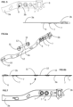
- THE figures 1, 2 And 3 represent a protective helmet 1 comprising a cap 2 made of a material preventing it from folding back on itself.
- the cap 2 may preferably be made of plastic material, for example injected polycarbonate or ABS or polystyrene or expanded polypropylene, or any other plastic material, in particular injected plastic, thermoformed or foam.
- the cap 2 comprises a frontal part 2a located at the front, that is to say close to the user's forehead, and an occipital part 2b located at the rear.
- the frontal part 2a is separated from the occipital part 2b, by two lateral parts 2c respectively right and left.
- the protective helmet 1 is provided with a head support 3 and a neck strap 4.
- the head support 3 is fixed to the cap 2 so as to form a U.
- the U-shaped head support 3 is closed by the neck strap 4 to go around the user's head.
- the head support 3 comprises a front part 3a and two side parts 3b respectively right and left as illustrated in figures 3 , 10 and 11 .
- the two side parts 3b are separated by the front part 3a.
- the head support 3 is intended to come into contact with the user's head.
- the front part 1a is intended to come into contact with the user's forehead while each of the parts lateral 3b is intended to come into contact with the lateral parts of the user's head.
- the head support 3 is intended to separate the head and the cap 2.
- the head support 3 is fixed to the cap 2. More precisely, the front part 3a of the head support 3 is fixed to the front part 2a of the cap 2 by one or more front fixing points 11. The two ends of the head support 3 are fixed to the side parts 2c of the cap 2 by first and second fixing points 6.
- the first and second fixing points 6 are advantageously arranged in the rear part of the cap 2, that is to say in the rear half of the cap 2 relative to the median front plane of the cap 2.
- the helmet 1 comprises head support adjustment means 3 which are configured to adjust the length of the head support 3.
- the head support 3 is adjustable so as to define several different values of head support 3 length.
- the length of the head support 3 is modified between the first and second fixing points 6.
- the first and second fixing points 6 are fixed on the shell 2 independently of the length of the head support 3.
- the adjustment means of the head support 3 are able to adjust the separation distance between the front part 3a of the head support 3 and the front part 2a of the cap 2.
- Increasing the effective length of the head support 3 corresponds to a move closer together between the front part 3a of the head support 3 and the front part 2a of the cap 2.
- Reducing the effective length of the head support 3 corresponds to an increase in the gap between the front part 3a of the head support 3 and the front part 2a of the cap 2.
- the adjustment means modulate the length of the head support 3 so as to modulate the distance between the front part 3 of the head support 3 and the front part 2a of the cap 2.
- Adjusting the length of the head support 3 makes it possible to define the position of the user's forehead relative to the front part 2a of the cap 2 and therefore intervenes in the centering of the head inside the helmet.
- a head support 3 in the form of a U associated with ends fixedly mounted on the cap 2 the adjustment of the length of the head support head 3 allows the position of the front part 3a to be adjusted simply and precisely.
- the neckband 4 is mounted to be movable relative to the front part 3a of the head support 3 and to the front part 2a of the skull cap 2.
- the neckband 4 is mounted to be movable relative to the front part 3a of the head support 3 so as to modulate the space available between the neckband 4 and the front part of the skull cap 2 and to press the user's forehead against the front part 3a.
- the movement of the neckband 4 makes it possible to define the spacing between the occipital part 2b of the skull cap 2 and the occipital bone.
- the neckband 4 presses on the occipital part of the head to press the forehead against the frontal part 3a of the head support 3 and thus define the position of the head relative to the skullcap 2.
- the helmet 1 comprises means for adjusting the position of the neckband 4 which are configured to define the position of the neckband 4 relative to the front part 3a of the head support 3.
- the means for adjusting the neckband 4 are distinct from the means for adjusting the length of the head support 3 to independently adjust the neckband 4 and the head support 3.
- the movement of the neckband 4 and the adjustment of the head support 3 make it possible to center the head in the skullcap 2 by independently defining the distance between the occipital part of the skullcap 2 and the neckband 4 on the one hand and the distance between the front part of the head support 3 and the front part of the skullcap 2 on the other hand.
- the adjustment means of the neckband 4 make it possible to define the separation distance between the neckband 4 and the front part 3a of the head support 3.
- the helmet 1 can be better centered on the user's head by using adjustment means independent of the position of the forehead relative to the frontal part of the cap 2 and the position of the occipital bone relative to the occipital part of the cap 2.
- the means for adjusting the neckband 4 are fixed on the one hand to the neckband 4 and they are fixed on the other hand to the front part 2a of the cap 2 and/or to the front part 3a of the head support 3 so as to define the distance between the neckband 4 and the front part 3a of the head support 3.
- the means for adjusting the neckband 4 are fixed to the front part 2a of the cap 2.
- the adjustment means of the head support 3 are configured such that the front part 3a of the head support 3 is mounted to be movable relative to each of the side parts 3b in a longitudinal direction of the head support 3.
- the longitudinal direction is substantially included in a transverse plane of the user. In the illustrated configuration, the head support 3 does not define a ring.
- the longitudinal direction extends from one end of the head support 3 to the opposite end along the largest dimension. The longitudinal direction connects the two fixing points 6 with the cap 2.
- the neckband 4 has two additional attachment points with the skull cap 2.
- the two additional attachment points are fixed on the skull cap 2 independently of the length of the head support 3.
- the neckband 4 can have any configuration insofar as the position of the neckband 4 is adjustable independently of the length of the head support 3.
- the two additional attachment points of the neckband 4 correspond to the first and second attachment points 6 between the head support 3 and the skull cap 2.
- the same attachment point 6 is used to attach the neckband 4 and the head support 3 to the skull cap 2.
- the neckband 4 is pivotally mounted about at least one pivot axis 5 relative to the occipital portion 2b of the skull cap 2.
- the neckband 4 is pivotally mounted relative to two pivot axes 5 which are not collinear and advantageously non-orthogonal. The movement of the neckband 4 relative to the front part 3a of the head support 3 results in a deformation of the neckband 4 so that in the absence of stress by the adjustment means of the neckband 4, the neckband 4 is in a rest position. The rest position is independent of the length of the head support 3.
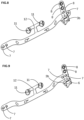
- the neckband 4 presses the user's forehead against the front part 3a of the head support 3, which results in a user whose head is offset towards the front part 2a of the cap 2.
- FIG. figure 4 Such a configuration is illustrated in FIG. figure 4 .
- This configuration can be a source of discomfort. It is therefore particularly interesting to bring the occipital part of the head closer to the occipital part of the cap 2.
- the helmet according to the invention makes it possible to recenter the helmet by increasing the distance between the front part 2a of the cap 2 and the front part 3a of the head support 3 by reducing the length of the head support 3.
- the neckband 4 is pivotally mounted and preferably by means of the two pivot axes 5 which are mounted fixed relative to the cap 2 independently of the length of the head support 3.
- the two lateral parts 3b of the head support 3 are fixed on the two lateral parts 2b of the cap 2 so that the at least one pivot axis 5 is stationary relative to the cap 2.
- the pivoting connection between the head support 3 and the neckband 4 does not move despite the modulation of the length of the head support 3.
- the user defines the distance between the front part 3a and the front part 2a. He can then fix the helmet 1 on the head using the neckband 4 which deforms. The deformation of the neckband 4 is intended to push the forehead against the front part 3a.
- the adjustment means of the head support 3 are configured to allow the definition of an infinite number of different values of length of the head support 3, for example by using a strap that cooperates with a strap blocker.
- adjustment means that are configured so that the frontal part 3a and the occipital part 3b of the head support 3 define a plurality of predefined positions corresponding to a plurality of values of length of the head support 3, with a finite number of possibilities, for example less than 5 different adjustment possibilities.
- the adjustment means are configured so as to define 2 or 3 different lengths of the head support 3.
- This adjustment of the length of the head support 3 makes it possible to adapt a single dimension of cap 2 to a greater variety of user head circumference dimensions. Using a predefined number of head support length values 3 or less than 5 seems sufficient to ensure good comfort of use for different head sizes.
- each lateral part 3b of the head support 3 is fixed to the lateral part 2c of the shell 2 by means of a rigid connection 6. It is particularly advantageous for each lateral part 3b of the head support 3 to be mounted removably relative to the lateral part 2c of the shell 2. This makes it possible to dismantle at least part of the head support 3 to facilitate its adjustment. It is also advantageous for the front part 3a of the head support 3 to be mounted immovably relative to the shell 2.
- the two lateral parts 3b of the head support 3 are formed by two parts mounted movably relative to the front part 3a.
- the two lateral parts 3b are mounted movably independently of each other relative to the front part 3a.
- the two lateral parts 3b are connected to each other, on the one hand, by the front part 3a and connected to each other on the other hand by the neck strap 4.
- Each of the two side parts 3b is fixed to the neckband 4 by means of a rotation shaft defining the axis 5.
- the two pivot shafts 5 provide the connection between a connecting end of the neckband 4 and one of the two side portions 3b of the head support 3.
- Each side portion 3b is fixed to the cap 2 such that the two connecting ends of the neckband 4 are fixed or substantially fixed relative to the cap 2.
- each lateral part 3b of the head support 3 is removably mounted relative to the front part 3a of the head support 3 in order to facilitate the adjustment of the length of the head support 3 and the overlap distance between the front part 3a and the lateral part 3b.
- the adjustment means of the head support 3 are configured to define a plurality of distinct adjustment positions defining several different values of length of the head support 3.
- the front part 3a defines a plurality of protruding areas 7 and the side part 3b defines holes 8 which are inserted into the protruding areas 7. The cooperation between the protruding areas 7 and the holes 8 defines at least two different lengths of head support 3.
- figure 5 illustrates a connection configuration between one end of the front part 3a and a side part 3b of the head support 3.
- the protruding areas and the holes can be interchanged between the front part and the side part.
- FIG. 6a illustrates a head support 3 with the front part 3 connected to the right side part 3b.
- the left end of the head support 3 is not connected to the left side part 3b.
- the front part 3a has two front attachment points 11 connected by a connector defining two axes of rotation 12 allowing the head support 3 to move relative to the cap 2.
- the Figure 6b illustrates a head support 3 with the front part 3 connected to the left side part 3b.
- one of the protruding zones 7 is configured to allow the attachment or detachment between the front part 3a and the side part 3b when the side part 3b and the front part 3a define a first orientation or configuration and to prohibit the detachment between the front part 3a and the side part 3b when the side part 3b and the front part 3a are in a second orientation/configuration different from the first orientation/configuration.
- the front part 3a can define a protruding area 7 which cooperates with another hole 8 so as to define a second connection point which blocks the position of the front part 3a relative to the lateral part 3b and prevents the rotation of the lateral part 3b relative to the front part 3a and maintains the front part 3a and the occipital part 3b which prevents separation.
- the front part 3a of the head support 3 is provided with two connection members configured to cooperate with two complementary connection members arranged on the occipital part 3b.
- the figure 5 illustrates a configuration where the front part 3a and the side part 3b define a head support 3 of reduced length while the figure 7 illustrates a configuration where the frontal part 3a and the occipital part 3b define a head support of greater length.
- the mechanical connection between the front part 3a of the head support 3 and the front part 2a of the cap 2 defines at least two axes of rotation arranged so that when the front part 3a of the head support 3 moves away from the front part 2a of the cap 2, the front part 3a of the head support 3 moves closer to the top of the cap 2.
- This configuration makes it possible to maintain a mechanical connection between the front part 2a and the front part 2a of the cap 2. 3a regardless of the value set by the head support 3 and provide good comfort to the user.
- the front part 3a has one or more connectors 11 which fix the front part 3a of the head support 3 on the front part 2a of the cap 2.
- the connectors 11 are offset relative to an axis which connects the two connection members with the occipital part 3b.
- the connectors 11 are separated from the axis which connects the two connection members by two axes of rotation 12.
- the two axes of rotation 12 allow the offset between the front part of the cap 2a and the front part of the head support 3a while allowing the front part of the head support 3 to adapt well to the shape of the forehead.
- the front part 3a of the head support 3 remains fixed to the front part 2a of the cap 2 in order to provide sufficient mechanical strength in use and to prevent the cap 2 from tilting relative to the head support 3.
- the two axes of rotation 12 are advantageously parallel to each other and parallel to the longitudinal axis of the head support 3.
- the connectors 11 of the front part 3a and the fixing points 6 of the occipital part 3b are separated by the adjustment means and preferably by the fixing members so that the head support 3 is in tension between the fixing points 6 and the front part 3a when the helmet 1 is tightened on the user's head.
- the front part 3a has two connectors 11 arranged on either side of the median sagittal plane of the helmet 1.
- the means for adjusting the neckband 4 may be formed by a rope or a strap fixed on the one hand to the neckband 4 and on the other hand to the skullcap 2 or to the head support 3.
- the rope or strap is preferably associated with a blocking means, for example a buckle, a hook or a tanka-type blocker. It is also possible to use a wheel or rack adjustment system.
- the internal part of the top of the cap 2 is covered with foam to avoid direct contact between the head and the cap and to absorb shocks.
- Such a configuration is of particular interest for protective helmets intended for communities and which must adapt to the greatest number while remaining comfortable and allowing simple adjustment.
- the system for adjusting the length of the head support 3 is separate from the system for adjusting the neck strap 4.
- the novice user will be able to deal only with adjusting the neck strap 4 by means of a conventional adjustment system.
- the head support 3 is adjusted beforehand to define its effective length and therefore an accessible range of head circumference.
- FIGS. 8 and 9 illustrate the installation of a side part 3b on the front part 3a.
- the side part 3b is presented facing the front part 3a according to a first orientation in order to allow the insertion of a protruding zone 7 in one of the holes as illustrated in figure 8 .
- the side part 3b is fixed to the front part 3a as illustrated in the figure 9 then the side part rotates relative to the front part 3a so as to prevent detachment.
- a second projecting element 7 is inserted into a second hole 8 to prevent rotation between the side part 3b and the front part 3a.
- FIG 10 illustrates the movement of the neckband 4 towards the front part 3a of the head support 3 as the neckband 4 is tightened compared to the figure 3 .
- figure 11 illustrates the evolution of the position of the frontal part 3a in comparison with the figure 3 .
Landscapes
- Helmets And Other Head Coverings (AREA)
Claims (8)
- Schutzhelm (1), umfassend:- eine Helmschale (2), versehen mit einem Stirnabschnitt (2a), einem Hinterkopfabschnitt (2b) und einem ersten und einem zweiten Seitenabschnitt (2c), die jeweils den Stirnabschnitt (2a) vom Hinterkopfabschnitt (2b) trennen,- eine Kopfhalterung (3), die an der Helmschale (2) befestigt ist, um ein U zu bilden, wobei die Kopfhalterung (3) einen Stirnabschnitt (3a) und einen ersten und einen zweiten Seitenabschnitt (3b) umfasst, die durch den Stirnabschnitt (3a) getrennt sind,- einen ersten Befestigungspunkt (6), der ein erstes Ende der Kopfhalterung (3) am ersten Seitenabschnitt (2c) der Helmschale (2) befestigt,- einen zweiten Befestigungspunkt (6), der ein zweites Ende der Kopfhalterung (3) am zweiten Seitenabschnitt (2c) der Helmschale (2) befestigt,- Mittel zum Einstellen der Kopfhalterung (3), die dazu konfiguriert sind, die Länge der Kopfhalterung (3) zwischen dem ersten und dem zweiten Befestigungspunkt (6) zu vergrößern oder zu verkleinern, wobei die Mittel zum Einstellen der Kopfhalterung (3) an der Grenzfläche zwischen dem Stirnabschnitt (3a) und jedem vom ersten und zweiten Seitenabschnitt (3b) der Kopfhalterung (3) angeordnet sind, wobei die Mittel zum Einstellen der Kopfhalterung (3) über den Stirnabschnitt (3a) und den ersten und zweiten Seitenabschnitt (3b) der Kopfhalterung (3) an der Helmschale (2) befestigt sind, wobei die Mittel zum Einstellen der Kopfhalterung (3) zwischen einem Befestigungspunkt (11) des Stirnabschnitts (3a) der Kopfhalterung (3) und jedem der ersten und zweiten Befestigungspunkte (6) des ersten und zweiten Seitenabschnitts (3b) der Kopfhalterung (3) angeordnet sind,- ein Nackenband (4), das beweglich montiert ist, um sich dem Stirnabschnitt (3a) der Kopfhalterung (3) anzunähern oder sich von diesem zu entfernen, wobei der Schutzhelm dadurch gekennzeichnet ist, dass:
das Nackenband (4) zwei zusätzliche Befestigungspunkte mit der Helmschale (2) aufweist, wobei die zwei zusätzlichen Befestigungspunkte unabhängig von der Länge der Kopfhalterung (3) fest an der Helmschale (2) montiert sind,- und dadurch, dass der Schutzhelm Mittel zum Einstellen der Position des Nackenbands (4) aufweist, die dazu konfiguriert sind, die Position des Nackenbands (4) in Bezug auf den Stirnabschnitt (3a) der Kopfhalterung (3) zu definieren, wobei die Mittel zum Einstellen der Position des Nackenbands (4) von den Mitteln zum Einstellen der Kopfhalterung (3) getrennt sind, um die Position des Nackenbands (4) und die Länge der Kopfhalterung (3) unabhängig voneinander einzustellen, und- der Befestigungspunkt (11), durch welchen der Stirnabschnitt (3a) der Kopfhalterung (3) an den Stirnabschnitt (2a) der Helmschale (2) befestigt ist, derart verformbar ist, dass eine Vergrößerung der Länge der Kopfhalterung (3) einer Annäherung zwischen dem Stirnabschnitt (3a) der Kopfhalterung (3) und dem Stirnabschnitt (2a) der Helmschale (2) entspricht, und dass eine Verringerung der Länge der Kopfhalterung (3) einer Entfernung des Stirnabschnitts (3a) der Kopfhalterung (3) vom Stirnabschnitt (2a) der Helmschale (2) entspricht, wobei der Stirnabschnitt (3a) der Kopfhalterung (3) relativ zum ersten und zweiten Befestigungspunkt (6) beweglich montiert ist. - Schutzhelm (1) nach dem vorherigen Anspruch, wobei das Nackenband (4) am ersten und zweiten Befestigungspunkt (6) jeweils um zwei nicht kollineare und nicht orthogonale Schwenkachsen (5) herum schwenkbar montiert ist, wobei die Position der zwei Schwenkachsen (5) in Bezug auf die Helmschale (2) mit der Längenentwicklung der Kopfhalterung (3) unverändert bleibt.
- Schutzhelm (1) nach einem der Ansprüche 1 und 2, wobei der Stirnabschnitt (3a) und der erste und zweite Seitenabschnitt (3b) der Kopfhalterung (3) eine Vielzahl von vordefinierten Positionen definieren, die einer Vielzahl von Längenwerten der Kopfhalterung (3) entsprechen.
- Schutzhelm (1) nach einem der vorherigen Ansprüche, wobei der erste Befestigungspunkt (6) und der zweite Befestigungspunkt (6) starre und abnehmbare Verbindungspunkte sind.
- Schutzhelm (1) nach einem der Ansprüche 1 bis 4, wobei die mechanische Verbindung zwischen dem Stirnabschnitt (3a) der Kopfhalterung (3) und der Helmschale (2) mindestens zwei Drehachsen (10) definiert, die derart angeordnet sind, dass der Stirnabschnitt (3a) der Kopfhalterung (3) sich dem Scheitel der Helmschale (2) annähert, wenn der Stirnabschnitt (3a) der Kopfhalterung (3) sich vom Stirnabschnitt (2a) der Helmschale (2) entfernt.
- Schutzhelm (1) nach einem der Ansprüche 1 bis 5, wobei die Mittel zum Einstellen der Position des Nackenbands (4) durch ein flexibles Element gebildet werden, das das Nackenband (4) mit dem Stirnabschnitt (2a, 3a) der Helmschale (2) oder der Kopfhalterung (3) verbindet, und einen Blockierer, der einen ersten Zustand aufweist, der ein Gleiten entlang des flexiblen Elements zulässt und dazu konfiguriert ist, mehrere Blockierpositionen des Blockierers am flexiblen Element zu definieren, und einen zweiten Zustand, in welchem der Blockierer am flexiblen Element befestigt ist.
- Verfahren zum Einstellen eines Schutzhelms (1) nach einem der vorherigen Ansprüche, umfassend die folgenden aufeinanderfolgenden Schritte:- Vergrößern oder Verkleinern der Länge der Kopfhalterung (3), um den Stirnabschnitt (3a) der Kopfhalterung (3) und den Stirnabschnitt (2a) der Helmschale (2) einander anzunähern oder voneinander zu entfernen und eine Länge der Kopfhalterung (3) zu definieren, und- Einstellen des Abstands zwischen dem Nackenband (4) und dem Stirnabschnitt (3a) der Kopfhalterung (3).
- Verfahren zum Einstellen nach dem vorherigen Anspruch für einen Schutzhelm (1) nach Anspruch 4, umfassend das Abnehmen der ersten und zweiten Befestigungspunkts in Bezug auf die Helmschale (2) vor dem Einstellen der Länge der Kopfhalterung (3) und das erneute Montieren des ersten und zweiten Befestigungspunkts vor dem Einstellen des Abstands zwischen dem Nackenband (4) und dem Stirnabschnitt (3a) der Kopfhalterung (3).
Applications Claiming Priority (1)
| Application Number | Priority Date | Filing Date | Title |
|---|---|---|---|
| FR2003798A FR3109275B1 (fr) | 2020-04-15 | 2020-04-15 | Casque de protection a reglage perfectionne |
Publications (2)
| Publication Number | Publication Date |
|---|---|
| EP3895571A1 EP3895571A1 (de) | 2021-10-20 |
| EP3895571B1 true EP3895571B1 (de) | 2024-11-27 |
Family
ID=70918686
Family Applications (1)
| Application Number | Title | Priority Date | Filing Date |
|---|---|---|---|
| EP21166851.2A Active EP3895571B1 (de) | 2020-04-15 | 2021-04-02 | Schutzhelm mit perfektionierter regulierung und regulierungsverfahren |
Country Status (4)
| Country | Link |
|---|---|
| US (1) | US11717046B2 (de) |
| EP (1) | EP3895571B1 (de) |
| CN (1) | CN217039038U (de) |
| FR (1) | FR3109275B1 (de) |
Families Citing this family (2)
| Publication number | Priority date | Publication date | Assignee | Title |
|---|---|---|---|---|
| DE102019008043A1 (de) * | 2019-11-20 | 2021-05-20 | Dräger Safety AG & Co. KGaA | Kopfschutzsystem |
| FR3163246A1 (fr) | 2024-06-18 | 2025-12-19 | Zedel | Casque et procédé de fabrication |
Family Cites Families (4)
| Publication number | Priority date | Publication date | Assignee | Title |
|---|---|---|---|---|
| FR2687902B1 (fr) | 1992-02-27 | 1997-03-21 | Petzl Ets | Casque de securite a reglage du dispositif de maintien sur la tete. |
| DE20312928U1 (de) * | 2003-08-18 | 2003-11-06 | Knauer, Hans-Georg, 71691 Freiberg | Helm |
| US9307802B2 (en) * | 2012-10-22 | 2016-04-12 | Revision Military S.A.R.L. | Helmet suspension system |
| FR3020924B1 (fr) | 2014-05-16 | 2016-06-24 | Zedel | Serre-nuque basculant pour casque de protection |
-
2020
- 2020-04-15 FR FR2003798A patent/FR3109275B1/fr active Active
-
2021
- 2021-04-02 EP EP21166851.2A patent/EP3895571B1/de active Active
- 2021-04-15 CN CN202120775585.XU patent/CN217039038U/zh active Active
- 2021-04-15 US US17/231,680 patent/US11717046B2/en active Active
Also Published As
| Publication number | Publication date |
|---|---|
| FR3109275A1 (fr) | 2021-10-22 |
| EP3895571A1 (de) | 2021-10-20 |
| CN217039038U (zh) | 2022-07-26 |
| FR3109275B1 (fr) | 2022-05-13 |
| US20210321708A1 (en) | 2021-10-21 |
| US11717046B2 (en) | 2023-08-08 |
Similar Documents
| Publication | Publication Date | Title |
|---|---|---|
| EP3790422B1 (de) | Schutzhelm mit mechanischem grössenverstellsystem | |
| CA2349764C (fr) | Perfectionnement pour casque de protection | |
| EP2944208B1 (de) | Schwenkbare nackenfixierung für schutzhelm | |
| EP3154385B1 (de) | Kopfbedeckung für kopfschutz | |
| CA2382804C (fr) | Casque de protection et ses moyens de connexion d'un accessoire | |
| CA2262022C (fr) | Perfectionnement pour moyens de maintien d'un casque de protection | |
| EP3895571B1 (de) | Schutzhelm mit perfektionierter regulierung und regulierungsverfahren | |
| FR3097107A1 (fr) | Bandeau de tête | |
| FR2978904A1 (fr) | Ensemble casque et masque de protection oculaire | |
| WO1997025832A1 (fr) | Perfectionnement pour dispositif de communication du type electroacoustique destine a equiper un casque de protection | |
| EP3231307B1 (de) | Sporthelm | |
| EP4666893A1 (de) | Helm und herstellungsverfahren | |
| WO2016008902A1 (fr) | Casque de protection a visiere mobile integree | |
| EP1740066B1 (de) | Verbesserungen an schutzhelmen | |
| EP3157368B1 (de) | Mit brille ausgestatteter helm, insbesondere zum ski- oder motorradfahren | |
| EP3289906A1 (de) | Schutzhelm mit kinnriemensystem | |
| FR3079720A1 (fr) | Casque avec protege-visiere | |
| EP1601260A1 (de) | Brille für einen schutzhelm und schutzhelm ausgestattet mit dieser brille | |
| WO1998056270A1 (fr) | Dispositif d'assujettissement d'un casque sur la tete d'un utilisateur, notamment d'un cycliste | |
| FR3051330A1 (fr) | Casque ajuste | |
| FR2780862A1 (fr) | Casque de protection du type a coque externe constituee de deux demi-coques | |
| EP2026672B1 (de) | Verbesserung bei einer stirnbandeinlage für einen schutzhelm | |
| CA2243290C (fr) | Perfectionnement pour dispositif de communication du type electroacoustique destine a equiper un casque de protection | |
| FR2599922A1 (fr) | Un dispositif d'ecoute | |
| FR2835711A1 (fr) | Equipement de tete muni d'un dispositif de communication |
Legal Events
| Date | Code | Title | Description |
|---|---|---|---|
| PUAI | Public reference made under article 153(3) epc to a published international application that has entered the european phase |
Free format text: ORIGINAL CODE: 0009012 |
|
| STAA | Information on the status of an ep patent application or granted ep patent |
Free format text: STATUS: THE APPLICATION HAS BEEN PUBLISHED |
|
| AK | Designated contracting states |
Kind code of ref document: A1 Designated state(s): AL AT BE BG CH CY CZ DE DK EE ES FI FR GB GR HR HU IE IS IT LI LT LU LV MC MK MT NL NO PL PT RO RS SE SI SK SM TR |
|
| B565 | Issuance of search results under rule 164(2) epc |
Effective date: 20210916 |
|
| STAA | Information on the status of an ep patent application or granted ep patent |
Free format text: STATUS: REQUEST FOR EXAMINATION WAS MADE |
|
| 17P | Request for examination filed |
Effective date: 20220330 |
|
| RBV | Designated contracting states (corrected) |
Designated state(s): AL AT BE BG CH CY CZ DE DK EE ES FI FR GB GR HR HU IE IS IT LI LT LU LV MC MK MT NL NO PL PT RO RS SE SI SK SM TR |
|
| GRAP | Despatch of communication of intention to grant a patent |
Free format text: ORIGINAL CODE: EPIDOSNIGR1 |
|
| STAA | Information on the status of an ep patent application or granted ep patent |
Free format text: STATUS: GRANT OF PATENT IS INTENDED |
|
| INTG | Intention to grant announced |
Effective date: 20240417 |
|
| GRAJ | Information related to disapproval of communication of intention to grant by the applicant or resumption of examination proceedings by the epo deleted |
Free format text: ORIGINAL CODE: EPIDOSDIGR1 |
|
| STAA | Information on the status of an ep patent application or granted ep patent |
Free format text: STATUS: REQUEST FOR EXAMINATION WAS MADE |
|
| GRAP | Despatch of communication of intention to grant a patent |
Free format text: ORIGINAL CODE: EPIDOSNIGR1 |
|
| STAA | Information on the status of an ep patent application or granted ep patent |
Free format text: STATUS: GRANT OF PATENT IS INTENDED |
|
| INTC | Intention to grant announced (deleted) | ||
| INTG | Intention to grant announced |
Effective date: 20240716 |
|
| GRAS | Grant fee paid |
Free format text: ORIGINAL CODE: EPIDOSNIGR3 |
|
| GRAA | (expected) grant |
Free format text: ORIGINAL CODE: 0009210 |
|
| STAA | Information on the status of an ep patent application or granted ep patent |
Free format text: STATUS: THE PATENT HAS BEEN GRANTED |
|
| AK | Designated contracting states |
Kind code of ref document: B1 Designated state(s): AL AT BE BG CH CY CZ DE DK EE ES FI FR GB GR HR HU IE IS IT LI LT LU LV MC MK MT NL NO PL PT RO RS SE SI SK SM TR |
|
| REG | Reference to a national code |
Ref country code: GB Ref legal event code: FG4D Free format text: NOT ENGLISH |
|
| REG | Reference to a national code |
Ref country code: CH Ref legal event code: EP |
|
| REG | Reference to a national code |
Ref country code: IE Ref legal event code: FG4D Free format text: LANGUAGE OF EP DOCUMENT: FRENCH |
|
| REG | Reference to a national code |
Ref country code: DE Ref legal event code: R096 Ref document number: 602021022282 Country of ref document: DE |
|
| REG | Reference to a national code |
Ref country code: LT Ref legal event code: MG9D |
|
| REG | Reference to a national code |
Ref country code: NL Ref legal event code: MP Effective date: 20241127 |
|
| PG25 | Lapsed in a contracting state [announced via postgrant information from national office to epo] |
Ref country code: PT Free format text: LAPSE BECAUSE OF FAILURE TO SUBMIT A TRANSLATION OF THE DESCRIPTION OR TO PAY THE FEE WITHIN THE PRESCRIBED TIME-LIMIT Effective date: 20250327 Ref country code: IS Free format text: LAPSE BECAUSE OF FAILURE TO SUBMIT A TRANSLATION OF THE DESCRIPTION OR TO PAY THE FEE WITHIN THE PRESCRIBED TIME-LIMIT Effective date: 20250327 Ref country code: HR Free format text: LAPSE BECAUSE OF FAILURE TO SUBMIT A TRANSLATION OF THE DESCRIPTION OR TO PAY THE FEE WITHIN THE PRESCRIBED TIME-LIMIT Effective date: 20241127 |
|
| PG25 | Lapsed in a contracting state [announced via postgrant information from national office to epo] |
Ref country code: FI Free format text: LAPSE BECAUSE OF FAILURE TO SUBMIT A TRANSLATION OF THE DESCRIPTION OR TO PAY THE FEE WITHIN THE PRESCRIBED TIME-LIMIT Effective date: 20241127 Ref country code: NL Free format text: LAPSE BECAUSE OF FAILURE TO SUBMIT A TRANSLATION OF THE DESCRIPTION OR TO PAY THE FEE WITHIN THE PRESCRIBED TIME-LIMIT Effective date: 20241127 |
|
| REG | Reference to a national code |
Ref country code: AT Ref legal event code: MK05 Ref document number: 1744805 Country of ref document: AT Kind code of ref document: T Effective date: 20241127 |
|
| PG25 | Lapsed in a contracting state [announced via postgrant information from national office to epo] |
Ref country code: BG Free format text: LAPSE BECAUSE OF FAILURE TO SUBMIT A TRANSLATION OF THE DESCRIPTION OR TO PAY THE FEE WITHIN THE PRESCRIBED TIME-LIMIT Effective date: 20241127 |
|
| PG25 | Lapsed in a contracting state [announced via postgrant information from national office to epo] |
Ref country code: ES Free format text: LAPSE BECAUSE OF FAILURE TO SUBMIT A TRANSLATION OF THE DESCRIPTION OR TO PAY THE FEE WITHIN THE PRESCRIBED TIME-LIMIT Effective date: 20241127 |
|
| PG25 | Lapsed in a contracting state [announced via postgrant information from national office to epo] |
Ref country code: NO Free format text: LAPSE BECAUSE OF FAILURE TO SUBMIT A TRANSLATION OF THE DESCRIPTION OR TO PAY THE FEE WITHIN THE PRESCRIBED TIME-LIMIT Effective date: 20250227 |
|
| PG25 | Lapsed in a contracting state [announced via postgrant information from national office to epo] |
Ref country code: LV Free format text: LAPSE BECAUSE OF FAILURE TO SUBMIT A TRANSLATION OF THE DESCRIPTION OR TO PAY THE FEE WITHIN THE PRESCRIBED TIME-LIMIT Effective date: 20241127 Ref country code: GR Free format text: LAPSE BECAUSE OF FAILURE TO SUBMIT A TRANSLATION OF THE DESCRIPTION OR TO PAY THE FEE WITHIN THE PRESCRIBED TIME-LIMIT Effective date: 20250228 Ref country code: AT Free format text: LAPSE BECAUSE OF FAILURE TO SUBMIT A TRANSLATION OF THE DESCRIPTION OR TO PAY THE FEE WITHIN THE PRESCRIBED TIME-LIMIT Effective date: 20241127 |
|
| PG25 | Lapsed in a contracting state [announced via postgrant information from national office to epo] |
Ref country code: PL Free format text: LAPSE BECAUSE OF FAILURE TO SUBMIT A TRANSLATION OF THE DESCRIPTION OR TO PAY THE FEE WITHIN THE PRESCRIBED TIME-LIMIT Effective date: 20241127 |
|
| PG25 | Lapsed in a contracting state [announced via postgrant information from national office to epo] |
Ref country code: RS Free format text: LAPSE BECAUSE OF FAILURE TO SUBMIT A TRANSLATION OF THE DESCRIPTION OR TO PAY THE FEE WITHIN THE PRESCRIBED TIME-LIMIT Effective date: 20250227 |
|
| PG25 | Lapsed in a contracting state [announced via postgrant information from national office to epo] |
Ref country code: SM Free format text: LAPSE BECAUSE OF FAILURE TO SUBMIT A TRANSLATION OF THE DESCRIPTION OR TO PAY THE FEE WITHIN THE PRESCRIBED TIME-LIMIT Effective date: 20241127 |
|
| PGFP | Annual fee paid to national office [announced via postgrant information from national office to epo] |
Ref country code: DE Payment date: 20250417 Year of fee payment: 5 |
|
| PG25 | Lapsed in a contracting state [announced via postgrant information from national office to epo] |
Ref country code: DK Free format text: LAPSE BECAUSE OF FAILURE TO SUBMIT A TRANSLATION OF THE DESCRIPTION OR TO PAY THE FEE WITHIN THE PRESCRIBED TIME-LIMIT Effective date: 20241127 |
|
| PGFP | Annual fee paid to national office [announced via postgrant information from national office to epo] |
Ref country code: GB Payment date: 20250423 Year of fee payment: 5 |
|
| PGFP | Annual fee paid to national office [announced via postgrant information from national office to epo] |
Ref country code: IT Payment date: 20250430 Year of fee payment: 5 |
|
| PG25 | Lapsed in a contracting state [announced via postgrant information from national office to epo] |
Ref country code: EE Free format text: LAPSE BECAUSE OF FAILURE TO SUBMIT A TRANSLATION OF THE DESCRIPTION OR TO PAY THE FEE WITHIN THE PRESCRIBED TIME-LIMIT Effective date: 20241127 |
|
| PGFP | Annual fee paid to national office [announced via postgrant information from national office to epo] |
Ref country code: FR Payment date: 20250428 Year of fee payment: 5 |
|
| PG25 | Lapsed in a contracting state [announced via postgrant information from national office to epo] |
Ref country code: RO Free format text: LAPSE BECAUSE OF FAILURE TO SUBMIT A TRANSLATION OF THE DESCRIPTION OR TO PAY THE FEE WITHIN THE PRESCRIBED TIME-LIMIT Effective date: 20241127 |
|
| PG25 | Lapsed in a contracting state [announced via postgrant information from national office to epo] |
Ref country code: SK Free format text: LAPSE BECAUSE OF FAILURE TO SUBMIT A TRANSLATION OF THE DESCRIPTION OR TO PAY THE FEE WITHIN THE PRESCRIBED TIME-LIMIT Effective date: 20241127 |
|
| PG25 | Lapsed in a contracting state [announced via postgrant information from national office to epo] |
Ref country code: CZ Free format text: LAPSE BECAUSE OF FAILURE TO SUBMIT A TRANSLATION OF THE DESCRIPTION OR TO PAY THE FEE WITHIN THE PRESCRIBED TIME-LIMIT Effective date: 20241127 |
|
| REG | Reference to a national code |
Ref country code: DE Ref legal event code: R097 Ref document number: 602021022282 Country of ref document: DE |
|
| PG25 | Lapsed in a contracting state [announced via postgrant information from national office to epo] |
Ref country code: SE Free format text: LAPSE BECAUSE OF FAILURE TO SUBMIT A TRANSLATION OF THE DESCRIPTION OR TO PAY THE FEE WITHIN THE PRESCRIBED TIME-LIMIT Effective date: 20241127 |
|
| PLBE | No opposition filed within time limit |
Free format text: ORIGINAL CODE: 0009261 |
|
| STAA | Information on the status of an ep patent application or granted ep patent |
Free format text: STATUS: NO OPPOSITION FILED WITHIN TIME LIMIT |
|
| REG | Reference to a national code |
Ref country code: CH Ref legal event code: L10 Free format text: ST27 STATUS EVENT CODE: U-0-0-L10-L00 (AS PROVIDED BY THE NATIONAL OFFICE) Effective date: 20251008 |
|
| 26N | No opposition filed |
Effective date: 20250828 |
|
| REG | Reference to a national code |
Ref country code: CH Ref legal event code: H13 Free format text: ST27 STATUS EVENT CODE: U-0-0-H10-H13 (AS PROVIDED BY THE NATIONAL OFFICE) Effective date: 20251125 |
|
| PG25 | Lapsed in a contracting state [announced via postgrant information from national office to epo] |
Ref country code: LU Free format text: LAPSE BECAUSE OF NON-PAYMENT OF DUE FEES Effective date: 20250402 |
|
| PG25 | Lapsed in a contracting state [announced via postgrant information from national office to epo] |
Ref country code: MC Free format text: LAPSE BECAUSE OF FAILURE TO SUBMIT A TRANSLATION OF THE DESCRIPTION OR TO PAY THE FEE WITHIN THE PRESCRIBED TIME-LIMIT Effective date: 20241127 |
|
| REG | Reference to a national code |
Ref country code: BE Ref legal event code: MM Effective date: 20250430 |
|
| PG25 | Lapsed in a contracting state [announced via postgrant information from national office to epo] |
Ref country code: BE Free format text: LAPSE BECAUSE OF NON-PAYMENT OF DUE FEES Effective date: 20250430 |
|
| PG25 | Lapsed in a contracting state [announced via postgrant information from national office to epo] |
Ref country code: CH Free format text: LAPSE BECAUSE OF NON-PAYMENT OF DUE FEES Effective date: 20250430 |