EP3894272B1 - Vehicle seat - Google Patents
Vehicle seat Download PDFInfo
- Publication number
- EP3894272B1 EP3894272B1 EP19831994.9A EP19831994A EP3894272B1 EP 3894272 B1 EP3894272 B1 EP 3894272B1 EP 19831994 A EP19831994 A EP 19831994A EP 3894272 B1 EP3894272 B1 EP 3894272B1
- Authority
- EP
- European Patent Office
- Prior art keywords
- reinforcement layer
- vehicle seat
- reinforcement
- outer end
- foam part
- Prior art date
- Legal status (The legal status is an assumption and is not a legal conclusion. Google has not performed a legal analysis and makes no representation as to the accuracy of the status listed.)
- Active
Links
- 230000002787 reinforcement Effects 0.000 claims description 80
- 239000006260 foam Substances 0.000 claims description 54
- 239000004744 fabric Substances 0.000 claims description 3
- 238000005187 foaming Methods 0.000 claims 1
- 239000010410 layer Substances 0.000 description 73
- 230000004048 modification Effects 0.000 description 9
- 238000012986 modification Methods 0.000 description 9
- 239000000463 material Substances 0.000 description 7
- 230000003014 reinforcing effect Effects 0.000 description 5
- 238000010304 firing Methods 0.000 description 3
- 230000000694 effects Effects 0.000 description 2
- 230000007704 transition Effects 0.000 description 2
- 210000001015 abdomen Anatomy 0.000 description 1
- 230000004308 accommodation Effects 0.000 description 1
- 239000011248 coating agent Substances 0.000 description 1
- 238000000576 coating method Methods 0.000 description 1
- 230000001427 coherent effect Effects 0.000 description 1
- 230000001419 dependent effect Effects 0.000 description 1
- 230000010354 integration Effects 0.000 description 1
- 238000003475 lamination Methods 0.000 description 1
- 239000010985 leather Substances 0.000 description 1
- 239000002245 particle Substances 0.000 description 1
- 230000001681 protective effect Effects 0.000 description 1
- 239000011241 protective layer Substances 0.000 description 1
- 230000003068 static effect Effects 0.000 description 1
- 239000004753 textile Substances 0.000 description 1
- 230000003313 weakening effect Effects 0.000 description 1
Images


Classifications
-
- B—PERFORMING OPERATIONS; TRANSPORTING
- B60—VEHICLES IN GENERAL
- B60N—SEATS SPECIALLY ADAPTED FOR VEHICLES; VEHICLE PASSENGER ACCOMMODATION NOT OTHERWISE PROVIDED FOR
- B60N2/00—Seats specially adapted for vehicles; Arrangement or mounting of seats in vehicles
- B60N2/70—Upholstery springs ; Upholstery
- B60N2/7017—Upholstery springs ; Upholstery characterised by the manufacturing process; manufacturing upholstery or upholstery springs not otherwise provided for
-
- B—PERFORMING OPERATIONS; TRANSPORTING
- B60—VEHICLES IN GENERAL
- B60N—SEATS SPECIALLY ADAPTED FOR VEHICLES; VEHICLE PASSENGER ACCOMMODATION NOT OTHERWISE PROVIDED FOR
- B60N2/00—Seats specially adapted for vehicles; Arrangement or mounting of seats in vehicles
- B60N2/64—Back-rests or cushions
-
- B—PERFORMING OPERATIONS; TRANSPORTING
- B60—VEHICLES IN GENERAL
- B60N—SEATS SPECIALLY ADAPTED FOR VEHICLES; VEHICLE PASSENGER ACCOMMODATION NOT OTHERWISE PROVIDED FOR
- B60N2/00—Seats specially adapted for vehicles; Arrangement or mounting of seats in vehicles
- B60N2/64—Back-rests or cushions
- B60N2/643—Back-rests or cushions shape of the back-rests
-
- B—PERFORMING OPERATIONS; TRANSPORTING
- B60—VEHICLES IN GENERAL
- B60N—SEATS SPECIALLY ADAPTED FOR VEHICLES; VEHICLE PASSENGER ACCOMMODATION NOT OTHERWISE PROVIDED FOR
- B60N2/00—Seats specially adapted for vehicles; Arrangement or mounting of seats in vehicles
- B60N2/64—Back-rests or cushions
- B60N2/646—Back-rests or cushions shape of the cushion
-
- B—PERFORMING OPERATIONS; TRANSPORTING
- B60—VEHICLES IN GENERAL
- B60N—SEATS SPECIALLY ADAPTED FOR VEHICLES; VEHICLE PASSENGER ACCOMMODATION NOT OTHERWISE PROVIDED FOR
- B60N2/00—Seats specially adapted for vehicles; Arrangement or mounting of seats in vehicles
- B60N2/70—Upholstery springs ; Upholstery
-
- B—PERFORMING OPERATIONS; TRANSPORTING
- B60—VEHICLES IN GENERAL
- B60R—VEHICLES, VEHICLE FITTINGS, OR VEHICLE PARTS, NOT OTHERWISE PROVIDED FOR
- B60R21/00—Arrangements or fittings on vehicles for protecting or preventing injuries to occupants or pedestrians in case of accidents or other traffic risks
- B60R21/02—Occupant safety arrangements or fittings, e.g. crash pads
- B60R21/16—Inflatable occupant restraints or confinements designed to inflate upon impact or impending impact, e.g. air bags
- B60R21/20—Arrangements for storing inflatable members in their non-use or deflated condition; Arrangement or mounting of air bag modules or components
- B60R21/207—Arrangements for storing inflatable members in their non-use or deflated condition; Arrangement or mounting of air bag modules or components in vehicle seats
-
- B—PERFORMING OPERATIONS; TRANSPORTING
- B60—VEHICLES IN GENERAL
- B60R—VEHICLES, VEHICLE FITTINGS, OR VEHICLE PARTS, NOT OTHERWISE PROVIDED FOR
- B60R21/00—Arrangements or fittings on vehicles for protecting or preventing injuries to occupants or pedestrians in case of accidents or other traffic risks
- B60R21/02—Occupant safety arrangements or fittings, e.g. crash pads
- B60R21/16—Inflatable occupant restraints or confinements designed to inflate upon impact or impending impact, e.g. air bags
- B60R21/20—Arrangements for storing inflatable members in their non-use or deflated condition; Arrangement or mounting of air bag modules or components
- B60R21/215—Arrangements for storing inflatable members in their non-use or deflated condition; Arrangement or mounting of air bag modules or components characterised by the covers for the inflatable member
- B60R21/2165—Arrangements for storing inflatable members in their non-use or deflated condition; Arrangement or mounting of air bag modules or components characterised by the covers for the inflatable member characterised by a tear line for defining a deployment opening
-
- B—PERFORMING OPERATIONS; TRANSPORTING
- B60—VEHICLES IN GENERAL
- B60N—SEATS SPECIALLY ADAPTED FOR VEHICLES; VEHICLE PASSENGER ACCOMMODATION NOT OTHERWISE PROVIDED FOR
- B60N2/00—Seats specially adapted for vehicles; Arrangement or mounting of seats in vehicles
- B60N2/58—Seat coverings
- B60N2002/5808—Seat coverings comprising opening zones for airbags
-
- B—PERFORMING OPERATIONS; TRANSPORTING
- B60—VEHICLES IN GENERAL
- B60R—VEHICLES, VEHICLE FITTINGS, OR VEHICLE PARTS, NOT OTHERWISE PROVIDED FOR
- B60R21/00—Arrangements or fittings on vehicles for protecting or preventing injuries to occupants or pedestrians in case of accidents or other traffic risks
- B60R21/02—Occupant safety arrangements or fittings, e.g. crash pads
- B60R21/16—Inflatable occupant restraints or confinements designed to inflate upon impact or impending impact, e.g. air bags
- B60R2021/161—Inflatable occupant restraints or confinements designed to inflate upon impact or impending impact, e.g. air bags characterised by additional means for controlling deployment trajectory
Definitions
- the invention relates to a vehicle seat with a seat part and a backrest, the backrest having a foam part with a cavity for at least partially accommodating an airbag device.
- the EP 1 199 227 A1 discloses a vehicle seat having an assembly consisting of a backrest and an airbag module, the backrest having a frame, padding and a trim part, and the airbag module having a chute attached to the frame.
- the trim part is rigid, while the padding in the area of the transition to the trim part is flexible so that a gap can be formed between the trim part and the padding for the airbag to emerge from the backrest by deforming the padding.
- a safety device for motor vehicles with at least one gas bag module that can be integrated into a vehicle seat, which comprises a prefabricated module unit that can be handled as a coherent whole and has at least one inflatable gas bag that serves in particular as a side airbag and a gas generator, with at least part of a rear wall of the vehicle seat forming structural element is also designed as a module cover for the module unit.
- the structural element has at least one area that can be broken open, torn open, swung open and/or pivoted away by the inflating gas bag, which is provided with a predetermined breaking point.
- the EP 2 960 116 B1 discloses a far side airbag device having a side airbag provided in a vehicle width direction on a vehicle center side of a seat back at a side portion, the side airbag having a rear inflation portion that inflates and deploys when gas is supplied, and the restrains at least rear portions of a seated occupant's chest and abdomen.
- a far-side airbag device can take into account the so-called secondary movements, ie the movements after the first airbag contact, of the vehicle occupants after an accident and mitigate their consequences.
- a vehicle is known with two individual seats arranged next to one another, which each contain a side airbag at least on their opposite sides, which is accommodated in an associated side bolster of the upper seat backrest area, the upper seat backrest areas with their side bolsters extending essentially laterally beyond the lower seat backrest areas extend close to the adjacent vehicle structure.
- a foam body of a vehicle seat with an airbag module is known, wherein the foam body is installed in a lateral area of the vehicle seat and has a receiving space for an airbag module.
- the foam body has a firing channel, which guides an airbag of the airbag module during expansion.
- a reinforcing layer which is designed as a knitted fabric element, is glued into the firing channel.
- a vehicle seat with a bolster covering a seat frame and attached to the seat frame.
- the vehicle seat has a seat cover covering the cushion pad and having an inflation portion to be inflated by an inflation force of an airbag.
- the vehicle seat has a webbing connected to the seat cover such that it transmits the inflation force of the airbag to the inflation portion, the webbing extending away from the seat cover and wherein the webbing has a fastening portion at its distal end portion.
- EP 0 990 566 A2 discloses an occupant protection device for attachment in a vehicle seat with a receptacle for an airbag, in which a strip of material is provided as the attachment means for a seat cover. This strip of material extends from a tear seam of the seat cover to an attachment point at which the strip of material is screwed to a carrier using a screw.
- the receptacle is located within a seat cushion.
- a vehicle seat with a side airbag including: an airbag module with an airbag cushion accommodated therein; a seat back frame, wherein the airbag module is attached to the seat back frame; and a seat back pad equipped with bolsters protruding on opposite sides.
- the cushion has an accommodation space to accommodate the airbag module.
- the seat back pad has a body part and a guide part to guide the deployment of the airbag cushion.
- the body part and the guide part are made of materials that have different levels of rigidity in relation to one another.
- the object of the invention is to improve a vehicle seat of the type mentioned at the outset, in particular to enable integration of a far-side airbag device.
- guiding a gas bag out of a foam part is to be improved.
- a predetermined tear point in a foam part should reliably allow the gas bag to emerge from the foam part.
- a foam particle flight during the deployment of the airbag should be minimized.
- a vehicle seat with a seat part and a backrest having a foam part with a cavity for at least partially accommodating an airbag device, the foam part being lined at least partially with a reinforcement layer arrangement in the region of the cavity, wherein in the case of a unfolding gas bag of the airbag device, the reinforcement layer arrangement guides the unfolding gas bag to a predetermined tear point of the foam part, and the reinforcement layer arrangement has a first reinforcement layer and a second reinforcement layer, the foam part having a first flange, a second flange and a flange connecting the first flange to the second flange Web has, which delimit the cavity, and an outer end portion of the first reinforcement layer and / or an outer end portion of the second reinforcement layer are foamed into the web / is.
- the foam part is at least partially lined with a reinforcement layer arrangement in the region of the cavity allows a far-side airbag device to be integrated into the backrest. In particular, guiding a gas bag out of the foam part is improved.
- An outer end region of the first reinforcement layer and an outer end region of the second reinforcement layer can form or accommodate a predetermined tear point of the foam part between them.
- the unfolding gas bag towards the predetermined tear point in order to prevent unwanted tearing of the foam part in other areas.
- the two reinforcement layers can be positioned relative to one another in such a way that they form and/or line a predetermined tear point in the foam part.
- the predetermined tear point can be formed as a notch in the foam part.
- the predetermined tear point can be formed as a weakening of the material in the foam part.
- the predetermined tear point can be formed as an incision in the foam part.
- the two reinforcement layers can be positioned at an angle to one another, thereby forming a predetermined tear point.
- a reinforcement layer which is arranged in front of the gas bag in the direction of travel, preferably has a particularly high strength.
- the reinforcement layer arrangement offers protection for the foam part against unintentional tearing and a guide for the gas bag.
- the web preferably runs predominantly parallel to a plane defined by a longitudinal direction and a vertical direction.
- the outer end area of the second reinforcement layer can be aligned approximately perpendicularly to the outer end area of the first reinforcement layer.
- the outer end area of the second reinforcement layer can run approximately parallel to the outer end area of the first reinforcement layer.
- the two reinforcing layers can overlap each other in sections. At least one of the two reinforcement layers can be a fleece. At least one of the reinforcement layers can be a protective layer. At least one of the reinforcement layers can be made of a fabric. At least one of the Reinforcing layers can be made of a plastic. At least one the reinforcement layers can be made of a textile. At least one of the two reinforcement layers can be made of leather.
- At least one of the reinforcing layers can be two-dimensional. At least one of the reinforcing layers can be three-dimensional. At least one of the reinforcement layers can be glued to the foam part. At least one of the reinforcement layers can be positively connected to the foam part. At least one of the reinforcement layers can be connected to the foam part by means of static friction. At least one of the reinforcement layers can be back-foamed with the foam part. At least one of the reinforcement layers can be foamed into the foam part at least in sections.
- a fleece or reinforcement material for reinforcement and another, angled fleece or reinforcement material can be arranged along the predetermined tear geometry.
- the foam part tears at the predetermined tear point along the first reinforcement layer (of the angled fleece) or along the second reinforcement layer or along both reinforcement layers.
- At least one of the reinforcement layers can be provided with an anti-adhesion effect by coating or lamination on the side facing the airbag.
- figure 1 shows schematically a vehicle seat 1 for a vehicle, in particular for a motor vehicle.
- the representation of the vehicle seat 1 in 1 is both for an embodiment, shown in figure 2 , As well as for three modifications of the embodiment shown in the Figures 3 to 5 , applicable.
- a longitudinal direction x When the vehicle seat 1 is installed in the vehicle, it runs largely horizontally and preferably parallel to a longitudinal direction of the vehicle, which corresponds to the usual direction of travel of the vehicle.
- a transverse direction y running perpendicularly to the longitudinal direction x is likewise aligned horizontally in the vehicle and runs parallel to a vehicle transverse direction.
- a vertical direction z runs perpendicular to the longitudinal direction x and perpendicular to the transverse direction y. In the case of a vehicle seat 1 installed in the vehicle, the vertical direction z runs parallel to the vertical axis of the vehicle.
- the position and direction information used such as front, rear, up and down, relates to a viewing direction of an occupant seated in the vehicle seat 1 in a normal seated position, with the vehicle seat 1 installed in the vehicle in a usage position suitable for passenger transport with an upright backrest 5 and, as usual, is aligned in the direction of travel.
- the vehicle seat 1 according to the invention can also be installed in a different orientation, for example transversely to the direction of travel.
- the vehicle seat 1 has a seat part 3 and the backrest 5 .
- An airbag device 8 is arranged in a cavity 7 in the backrest 5 .
- the airbag device 8 comprises a gas bag which, in the event of an accident, can deploy laterally (mainly parallel to the transverse direction y) in the direction of an adjacent vehicle seat or in the direction of a vehicle structure to protect a passenger seated in the vehicle seat 1 .
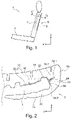
- figure 2 shows a section through a backrest 5 of a vehicle seat 1 according to the invention according to an embodiment.
- the backrest 5 has a 2 supporting backrest structure, not shown, a foam part 10 and an in 2 seat cover not shown.
- the foam part 10 has a front side 12 facing the occupant of the vehicle seat 1 and a rear side 14 facing away from the occupant.
- the cavity 7 accommodates the backrest structure, not shown in the figures, and the airbag device 8 .
- the cavity 7 is in the foam part 10 intended.
- the foam part 10 In an outer area of the cavity 7, the foam part 10 has a U-shaped cross section with a first flange 18, a web 20 and a second flange 22.
- the first flange 18 is an area of the foam part 10 facing the occupant and runs predominantly parallel to the transverse direction y.
- the first flange 18 transitions into the web 20 in the area of an outside of the vehicle seat 1 .
- the web 20 runs predominantly parallel to the longitudinal direction x.
- the web 20 merges into the second flange 22 .
- the second flange 22 is a region of the foam part 10 facing away from the occupant and runs predominantly parallel to the transverse direction y.
- the second flange 22 is sword-shaped and oriented toward a seat center of the vehicle seat 1 .
- the cavity 7 is open towards the center of the seat.
- a predetermined tear point 24 is formed in the web 20 of the foam part 10 that delimits the cavity 7 .
- the predetermined tear point 24 is designed as a notch in the foam part 10, which extends from the cavity 7 in the direction of the outside of the vehicle seat 1, in the present case predominantly in the transverse direction y.
- the predetermined crack point 24 runs through the web 20 only partially.
- the predetermined tear point 24 preferably extends in the vertical direction z over at least the entire height of the gas bag, in particular over the entire height of the cavity 7.
- the web 20 of the foam part 10 tears in the direction specified by the predetermined tear point 24 completely in such a way that the airbag (possibly after severing a tear seam in the seat cover) can emerge from the vehicle seat 1 and assume a protective position for the occupants.
- the foam part 10 is at least partially reinforced in the area of the airbag device 8 by a largely flat reinforcement layer arrangement 30, so that the foam part 10 can only tear in the event of an unfolding airbag, starting from the predetermined tear point 24 and only in a predetermined direction.
- the reinforcement layer arrangement 30 in the present case comprises a first reinforcement layer 32 and a second reinforcement layer 34, which in the present case are each formed as a separate, three-dimensionally shaped fleece.
- an outer end region 32.1 of the first reinforcement layer 32 is foamed into the web 20 of the foam part 10.
- the outer end area 32.1 runs parallel to the predetermined tear point 24, but penetrates deeper towards the outside of the seat into the web 20 than the predetermined tear point 24.
- the remaining area of the first reinforcement layer 32 forms a separating layer between the first flange 18 and the cavity 7 and runs out from the outer end area 32.1 in the direction of the center of the seat and ends in an inner end area 32.2.
- an outer end region 34.1 of the second reinforcement layer 34 is foamed into the web 20 of the foam part 10.
- An outer end area 34.1 runs along the predetermined tear point 24 and ends bluntly on the first reinforcement layer 32.
- the remaining area of the second reinforcement layer 34 forms a separating layer between the web 20 and the cavity 7 and, starting from the outer end area 34.1, runs predominantly parallel to the longitudinal direction x and ends in an inner end area 34.2.
- the first modification of the exemplary embodiment shown corresponds to the exemplary embodiment, with the exception of the differences described below, which is why components that are the same or have the same effect have the same reference symbols.
- a second reinforcement layer 134 is formed differently.
- the second reinforcement layer 134 is opposite to the second reinforcement layer 34 of FIG 2 illustrated embodiment viewed in the transverse direction y larger.
- an outer end region 134.1 of the second reinforcement layer 134 is foamed into the web 20 of the foam part 10.
- the outer end region 134.1 runs parallel to the predetermined tear point 24, but penetrates deeper into the web 20 towards the outside of the seat than the predetermined tear point 24.
- the outer End area 134.1 penetrates approximately as deep into the web 20 as an outer end area 32.1 of a first reinforcement layer 32.
- the remaining area of the second reinforcement layer 134 forms a separating layer between the second flange 22 and the cavity 7 and runs from the outer end area 134.1 in the direction the center of the seat and ends in an inner end area 134.2.
- one inside figure 4 illustrated second modification of the embodiment corresponds to the differences described below in figure 2 illustrated embodiment, which is why the same or equivalent components have the same reference numerals.
- a second reinforcement layer 234 is formed differently.
- the second reinforcement layer 234 is opposite to the second reinforcement layer 34 of FIG figure 2 illustrated embodiment viewed in the transverse direction y smaller.
- a tear course 236 is also shown, which results in the event of an accident through the unfolding airbag, starting from a predetermined tear point 24 .
- an outer end region 234.1 of the second reinforcement layer 234 meets the predetermined tear point 24 approximately perpendicularly, in particular perpendicularly.
- the second reinforcement layer 234 runs approximately linearly and ends in an inner end region 234.2.
- the outer end area 234.1 is preferably slightly spaced apart from the first reinforcement layer 32.
- one inside figure 5 shown third modification of the embodiment corresponds to the differences described below in figure 2 illustrated embodiment, which is why the same or equivalent components have the same reference numerals.
- a second reinforcement layer 334 is formed differently.
- a crack path 336 is also shown schematically, which results in the event of an accident through the unfolding airbag, starting from a predetermined crack point 24 .
- the second reinforcement layer 334 is opposite to the second reinforcement layer 34 of FIG figure 2 1 of the second reinforcement layer 334 runs exclusively parallel to a predetermined tear point 24 without contacting the first reinforcement layer 32.
- a distance between the outer end region 334.1 and the first reinforcement layer 32 corresponds approximately to the width of the predetermined tear point 24 in the longitudinal direction x.
Description
Die Erfindung betrifft einen Fahrzeugsitz mit einem Sitzteil und einer Rückenlehne, die Rückenlehne aufweisend ein Schaumteil mit einem Hohlraum zur wenigstens teilweisen Aufnahme einer Airbagvorrichtung.The invention relates to a vehicle seat with a seat part and a backrest, the backrest having a foam part with a cavity for at least partially accommodating an airbag device.
Die
Aus der
Die
Aus der
Aus der
Aus der
Aus der
Aus der
Der Erfindung liegt die Aufgabe zu Grunde, einen Fahrzeugsitz der eingangs genannten Art zu verbessern, insbesondere eine Integration einer Far-Side Airbagvorrichtung zu ermöglichen. Insbesondere soll eine Führung eines Gassackes aus einem Schaumteil heraus verbessert werden. Insbesondere soll eine Sollrissstelle in einem Schaumteil verlässlich ein Heraustreten des Gassackes aus dem Schaumteil ermöglichen. Ein Schaumpartikelflug während der Entfaltung des Gassackes soll minimiert werden.The object of the invention is to improve a vehicle seat of the type mentioned at the outset, in particular to enable integration of a far-side airbag device. In particular, guiding a gas bag out of a foam part is to be improved. In particular, a predetermined tear point in a foam part should reliably allow the gas bag to emerge from the foam part. A foam particle flight during the deployment of the airbag should be minimized.
Diese Aufgabe wird erfindungsgemäß gelöst durch einen Fahrzeugsitz mit einem Sitzteil und einer Rückenlehne, die Rückenlehne aufweisend ein Schaumteil mit einem Hohlraum zur wenigstens teilweisen Aufnahme einer Airbagvorrichtung, wobei das Schaumteil im Bereich des Hohlraums wenigstens teilweise mit einer Verstärkungsschichtanordnung ausgekleidet ist, wobei im Falle eines sich entfaltenden Gassackes der Airbagvorrichtung, die Verstärkungsschichtanordnung den sich entfaltenden Gassack zu einer Sollrissstelle des Schaumteils führt, und die Verstärkungsschichtanordnung eine erste Verstärkungsschicht und eine zweite Verstärkungsschicht aufweist, wobei das Schaumteil einen ersten Flansch, einen zweiten Flansch und einen den ersten Flansch mit dem zweiten Flansch verbindenden Steg aufweist, die den Hohlraum begrenzen, und ein äußerer Endbereich der ersten Verstärkungsschicht und/oder ein äußerer Endbereich der zweiten Verstärkungsschicht in den Steg eingeschäumt sind/ist.This object is achieved according to the invention by a vehicle seat with a seat part and a backrest, the backrest having a foam part with a cavity for at least partially accommodating an airbag device, the foam part being lined at least partially with a reinforcement layer arrangement in the region of the cavity, wherein in the case of a unfolding gas bag of the airbag device, the reinforcement layer arrangement guides the unfolding gas bag to a predetermined tear point of the foam part, and the reinforcement layer arrangement has a first reinforcement layer and a second reinforcement layer, the foam part having a first flange, a second flange and a flange connecting the first flange to the second flange Web has, which delimit the cavity, and an outer end portion of the first reinforcement layer and / or an outer end portion of the second reinforcement layer are foamed into the web / is.
Dadurch, dass das Schaumteil im Bereich des Hohlraums wenigstens teilweise mit einer Verstärkungsschichtanordnung ausgekleidet ist, ist eine Integration einer Far-Side-Airbagvorrichtung in die Rückenlehne ermöglicht. Insbesondere ist eine Führung eines Gassackes aus dem Schaumteil heraus verbessert.The fact that the foam part is at least partially lined with a reinforcement layer arrangement in the region of the cavity allows a far-side airbag device to be integrated into the backrest. In particular, guiding a gas bag out of the foam part is improved.
Vorteilhafte Ausgestaltungen, welche einzeln oder in Kombination miteinander eingesetzt werden können, sind Gegenstand der Unteransprüche.Advantageous configurations, which can be used individually or in combination with one another, are the subject matter of the dependent claims.
Ein äußerer Endbereich der ersten Verstärkungsschicht und ein äußerer Endbereich der zweiten Verstärkungsschicht können eine Sollrissstelle des Schaumteils zwischen sich bilden oder aufnehmen. Dadurch wird der sich entfaltende Gassack auf die Sollrissstelle zu geführt, um ein ungewolltes Einreißen des Schaumteils in anderen Bereichen zu verhindern.An outer end region of the first reinforcement layer and an outer end region of the second reinforcement layer can form or accommodate a predetermined tear point of the foam part between them. As a result, the unfolding gas bag towards the predetermined tear point in order to prevent unwanted tearing of the foam part in other areas.
Die zwei Verstärkungsschichten können derart zueinander positioniert sein, dass sie eine Sollrissstelle in dem Schaumteil ausbilden und/oder auskleiden. Die Sollrissstelle kann als eine Kerbe in dem Schaumteil ausgebildet sein. Die Sollrissstelle kann als eine Materialschwächung in dem Schaumteil ausgebildet sein. Die Sollrissstelle kann als ein Einschnitt in dem Schaumteil ausgebildet sein.The two reinforcement layers can be positioned relative to one another in such a way that they form and/or line a predetermined tear point in the foam part. The predetermined tear point can be formed as a notch in the foam part. The predetermined tear point can be formed as a weakening of the material in the foam part. The predetermined tear point can be formed as an incision in the foam part.
Die zwei Verstärkungsschichten können abgewinkelt zueinander positioniert sein, und dadurch eine Sollrissstelle ausbilden. Vorzugsweise weist eine Verstärkungsschicht, die in Fahrtrichtung vor dem Gassack angeordnet ist, eine besonders hohe Festigkeit auf. Die Verstärkungsschichtanordnung bietet Schutz für das Schaumteil vor einem ungewollten Zerreißen sowie eine Führung für den Gassack.The two reinforcement layers can be positioned at an angle to one another, thereby forming a predetermined tear point. A reinforcement layer, which is arranged in front of the gas bag in the direction of travel, preferably has a particularly high strength. The reinforcement layer arrangement offers protection for the foam part against unintentional tearing and a guide for the gas bag.
Der Steg verläuft vorzugsweise überwiegend parallel zu einer durch eine Längsrichtung und eine Vertikalrichtung definierten Ebene.The web preferably runs predominantly parallel to a plane defined by a longitudinal direction and a vertical direction.
In einem Bereich der Sollrissstelle des Schaumteils kann der äußere Endbereich der zweiten Verstärkungsschicht annähernd senkrecht zum äußeren Endbereich der ersten Verstärkungsschicht ausgerichtet sein.In an area of the predetermined tearing point of the foam part, the outer end area of the second reinforcement layer can be aligned approximately perpendicularly to the outer end area of the first reinforcement layer.
In einem Bereich der Sollrissstelle des Schaumteils kann der äußere Endbereich der zweiten Verstärkungsschicht annähernd parallel zum äußeren Endbereich der ersten Verstärkungsschicht verlaufen.In an area of the predetermined tearing point of the foam part, the outer end area of the second reinforcement layer can run approximately parallel to the outer end area of the first reinforcement layer.
Die beiden Verstärkungsschichten können einander abschnittsweise überlappen. Wenigstens eine der beiden Verstärkungsschichten kann ein Vlies sein. Wenigstens eine der Verstärkungsschichten kann eine Schutzlage sein. Wenigstens eine der Verstärkungsschichten kann aus einem Gewebe gefertigt sein. Wenigstens eine der Verstärkungsschichten kann aus einem Kunststoff gefertigt sein. Wenigstens eine der Verstärkungsschichten kann aus einem Textil gefertigt sein. Wenigstens eine der beiden Verstärkungsschichten kann aus einem Leder gefertigt sein.The two reinforcing layers can overlap each other in sections. At least one of the two reinforcement layers can be a fleece. At least one of the reinforcement layers can be a protective layer. At least one of the reinforcement layers can be made of a fabric. At least one of the Reinforcing layers can be made of a plastic. At least one the reinforcement layers can be made of a textile. At least one of the two reinforcement layers can be made of leather.
Wenigstens eine der Verstärkungsschichten kann zweidimensional ausgebildet sein. Wenigstens eine der Verstärkungsschichten kann dreidimensional ausgebildet sein. Wenigstens einer der Verstärkungsschichten kann mit dem Schaumteil verklebt sein. Wenigstens einer der Verstärkungsschichten kann formschlüssig mit dem Schaumteil verbunden sein. Wenigstens einer der Verstärkungsschichten kann mittels Haftreibung mit dem Schaumteil verbunden sein. Wenigstens einer der Verstärkungsschichten kann mit dem Schaumteil hinterschäumt sein. Wenigstens einer der Verstärkungsschichten kann wenigstens abschnittsweise in das Schaumteil eingeschäumt sein.At least one of the reinforcing layers can be two-dimensional. At least one of the reinforcing layers can be three-dimensional. At least one of the reinforcement layers can be glued to the foam part. At least one of the reinforcement layers can be positively connected to the foam part. At least one of the reinforcement layers can be connected to the foam part by means of static friction. At least one of the reinforcement layers can be back-foamed with the foam part. At least one of the reinforcement layers can be foamed into the foam part at least in sections.
Neben einer in einem dem Insassen abgewandten Bereich des Schaumteils (B-seitig) in das Schaumteil eingebrachten Sollrissgeometrie (Sollrissstelle, z.B. Schlitz) kann ein Vlies oder Verstärkungsmaterial zur Verstärkung und ein weiteres, abgewinkeltes Vlies oder Verstärkungsmaterial entlang der Sollrissgeometrie angeordnet sein. Das Schaumteil reißt dadurch an der Sollrissstelle entlang der ersten Verstärkungsschicht (des abgewinkelten Vlieses) oder entlang der zweiten Verstärkungsschicht oder entlang beider Verstärkungsschichten.In addition to a predetermined tear geometry (predetermined tear point, e.g. slit) introduced into the foam part in an area of the foam part facing away from the occupant (B-side), a fleece or reinforcement material for reinforcement and another, angled fleece or reinforcement material can be arranged along the predetermined tear geometry. As a result, the foam part tears at the predetermined tear point along the first reinforcement layer (of the angled fleece) or along the second reinforcement layer or along both reinforcement layers.
Wenigstens eine der Verstärkungsschichten kann durch Beschichtung oder Laminierung mit einer Anti-Haft-Wirkung auf der dem Airbag zugewandten Seite ausgerüstet sein.At least one of the reinforcement layers can be provided with an anti-adhesion effect by coating or lamination on the side facing the airbag.
Im Folgenden ist die Erfindung anhand eines in den Figuren dargestellten vorteilhaften Ausführungsbeispiels sowie drei Abwandlungen dieses Ausführungsbeispiels näher erläutert. Die Erfindung ist jedoch nicht auf dieses Ausführungsbeispiel und dessen Abwandlungen beschränkt. Es zeigen:
- Fig. 1:
- eine schematische Seitenansicht eines erfindungsgemäßen Fahrzeugsitzes,
- Fig. 2:
- einen Schnitt durch eine Rückenlehne des erfindungsgemäßen Fahrzeugsitzes gemäß des Ausführungsbeispiels, entlang der Linie I-I in
Fig. 1 , - Fig. 3:
- einen Schnitt durch eine Rückenlehne eines erfindungsgemäßen Fahrzeugsitzes gemäß einer ersten Abwandlung des Ausführungsbeispiels, entlang der Linie I-I in
Fig. 1 , - Fig. 4:
- einen Schnitt durch eine Rückenlehne eines erfindungsgemäßen Fahrzeugsitzes gemäß einer zweiten Abwandlung des Ausführungsbeispiels, entlang der Linie I-I in
Fig. 1 , und - Fig. 5:
- einen Schnitt durch eine Rückenlehne eines erfindungsgemäßen Fahrzeugsitzes gemäß einer dritten Abwandlung des Ausführungsbeispiels, entlang der Linie I-I in
Fig. 1 .
- Figure 1:
- a schematic side view of a vehicle seat according to the invention,
- Figure 2:
- a section through a backrest of the vehicle seat according to the invention according to the embodiment, along the line II in
1 , - Figure 3:
- a section through a backrest of a vehicle seat according to the invention according to a first modification of the embodiment, along the line II in
1 , - Figure 4:
- a section through a backrest of a vehicle seat according to the invention according to a second modification of the embodiment, along the line II in
1 , and - Figure 5:
- a section through a backrest of a vehicle seat according to the invention according to a third modification of the embodiment, along the line II in
1 .
Der Fahrzeugsitz 1 wird nachfolgend unter Verwendung von drei senkrecht zueinander verlaufenden Raumrichtungen beschrieben. Eine Längsrichtung x verläuft bei einem im Fahrzeug eingebauten Fahrzeugsitz 1 weitgehend horizontal und vorzugsweise parallel zu einer Fahrzeuglängsrichtung, die der gewöhnlichen Fahrtrichtung des Fahrzeugs entspricht. Eine zu der Längsrichtung x senkrecht verlaufende Querrichtung y ist im Fahrzeug ebenfalls horizontal ausgerichtet und verläuft parallel zu einer Fahrzeugquerrichtung. Eine Vertikalrichtung z verläuft senkrecht zu der Längsrichtung x und senkrecht zu der Querrichtung y. Bei einem im Fahrzeug eingebauten Fahrzeugsitz 1 verläuft die Vertikalrichtung z parallel zu der Fahrzeughochachse.The
Die verwendeten Positions- und Richtungsangaben, wie beispielsweise vorne, hinten, oben und unten beziehen sich auf eine Blickrichtung eines im Fahrzeugsitz 1 sitzenden Insassen in normaler Sitzposition, wobei der Fahrzeugsitz 1 im Fahrzeug eingebaut, in einer zur Personenbeförderung geeigneten Gebrauchsposition mit einer aufrechtstehenden Rückenlehne 5 und wie üblich in Fahrtrichtung ausgerichtet ist. Der erfindungsgemäße Fahrzeugsitz 1 kann jedoch auch in abweichender Ausrichtung, beispielsweise quer zur Fahrtrichtung verbaut werden.The position and direction information used, such as front, rear, up and down, relates to a viewing direction of an occupant seated in the
Der Fahrzeugsitz 1 weist ein Sitzteil 3 und die Rückenlehne 5 auf. In der Rückenlehne 5 ist in einem Hohlraum 7 eine Airbagvorrichtung 8 angeordnet. Die Airbagvorrichtung 8 umfasst einen Gassack, der sich im Falle eines Unfalls seitlich (überwiegend parallel zur Querrichtung y) in Richtung eines benachbarten Fahrzeugsitzes oder in Richtung einer Fahrzeugstruktur zum Schutz eines in dem Fahrzeugsitz 1 sitzenden Passagiers entfalten kann.The
Die Rückenlehne 5 weist eine in
In dem den Hohlraum 7 begrenzenden Steg 20 des Schaumteils 10 ist eine Sollrissstelle 24 ausgebildet. Die Sollrissstelle 24 ist vorliegend als eine Kerbe in dem Schaumteil 10 ausgebildet, die sich vom Hohlraum 7 in Richtung der Außenseite des Fahrzeugsitzes 1, vorliegend überwiegend in Querrichtung y, erstreckt. Die Sollrissstelle 24 durchläuft den Steg 20 nur teilweise. Die Sollrissstelle 24 erstreckt sich in Vertikalrichtung z vorzugsweise über wenigstens die gesamte Höhe des Gassackes, insbesondere über die gesamte Höhe des Hohlraums 7. Im Falle eines sich während eines Unfalls entfaltenden Gassackes reißt der Steg 20 des Schaumteils 10 in der durch die Sollrissstelle 24 vorgegebenen Richtung vollständig derart durch, dass der Gassack (ggf. nach Durchtrennen einer Reißnaht in dem Sitzbezug) aus dem Fahrzeugsitz 1 austreten und eine den Insassen schützende Position einnehmen kann.A
Das Schaumteil10 ist im Bereich der Airbagvorrichtung 8 zumindest teilweise durch eine weitgehend flächige Verstärkungsschichtanordnung 30 verstärkt, so dass das Schaumteil 10 im Falle eines sich entfaltenden Gassackes nur ausgehend von der Sollrissstelle 24 und nur in einer vorbestimmten Richtung reißen kann.The
Die Verstärkungsschichtanordnung 30 umfasst vorliegend eine erste Verstärkungsschicht 32 und eine zweite Verstärkungsschicht 34, die vorliegend jeweils als ein separates, dreidimensional geformtes Vlies ausgebildet sind.The
In Querrichtung y betrachtet ist ein äußerer Endbereich 32.1 der ersten Verstärkungsschicht 32 in den Steg 20 des Schaumteils 10 eingeschäumt. Der äußere Endbereich 32.1 verläuft parallel zur Sollrissstelle 24, dringt jedoch tiefer in Richtung der Sitzaußenseite in den Steg 20 ein, als die Sollrissstelle 24. Der übrige Bereich der ersten Verstärkungsschicht 32 bildet eine Trennschicht zwischen dem ersten Flansch 18 und dem Hohlraum 7 und verläuft ausgehend von dem äußeren Endbereich 32.1 in Richtung der Sitzmitte und endet in einem inneren Endbereich 32.2.Viewed in the transverse direction y, an outer end region 32.1 of the
In Querrichtung y betrachtet ist ein äußerer Endbereich 34.1 der zweiten Verstärkungsschicht 34 in den Steg 20 des Schaumteils 10 eingeschäumt. Ein äußerer Endbereich 34.1 verläuft entlang der Sollrissstelle 24 und endet stumpf auf der ersten Verstärkungsschicht 32. Der übrige Bereich der zweiten Verstärkungsschicht 34 bildet eine Trennschicht zwischen dem Steg 20 und dem Hohlraum 7 und verläuft ausgehend von dem äußeren Endbereich 34.1 überwiegend parallel zur Längsrichtung x und endet in einem inneren Endbereich 34.2.Viewed in the transverse direction y, an outer end region 34.1 of the
Eine in
In Querrichtung y betrachtet ist ein äußerer Endbereich 134.1 der zweiten Verstärkungsschicht 134 in den Steg 20 des Schaumteils 10 eingeschäumt. Der äußere Endbereich 134.1 verläuft parallel zur Sollrissstelle 24, dringt jedoch tiefer in Richtung der Sitzaußenseite in den Steg 20 ein, als die Sollrissstelle 24. Der äußere Endbereich 134.1 dringt annähern so tief in den Steg 20 ein wie ein äußerer Endbereich 32.1 einer ersten Verstärkungsschicht 32. Der übrige Bereich der zweiten Verstärkungsschicht 134 bildet eine Trennschicht zwischen dem zweiten Flansch 22 und dem Hohlraum 7 und verläuft ausgehend von dem äußeren Endbereich 134.1 in Richtung der Sitzmitte und endet in einem inneren Endbereich 134.2.Viewed in the transverse direction y, an outer end region 134.1 of the
Eine in
In Längsrichtung x betrachtet trifft ein äußerer Endbereich 234.1 der zweiten Verstärkungsschicht 234 annähernd senkrecht, insbesondere senkrecht, auf die Sollrissstelle 24. Ausgehend von dem äußerer Endbereich 234.1 verläuft die zweite Verstärkungsschicht 234 annähernd linear und endet in einem inneren Endbereich 234.2. Der äußerer Endbereich 234.1 ist vorzugsweise geringfügig beabstandet zur ersten Verstärkungsschicht 32.Viewed in the longitudinal direction x, an outer end region 234.1 of the
Eine in
Die zweite Verstärkungsschicht 334 ist gegenüber der zweiten Verstärkungsschicht 34 des in
Obwohl die Erfindung in den Figuren und der vorausgegangenen Darstellung im Detail beschrieben wurde, sind die Darstellungen illustrativ und beispielhaft und nicht einschränkend zu verstehen. Insbesondere ist die Wahl der zeichnerisch dargestellten Proportionen der einzelnen Elemente nicht als erforderlich oder beschränkend auszulegen.Although the invention has been described in detail in the figures and the previous illustration, the illustrations are to be understood as illustrative and exemplary and not restrictive. In particular, the selection of the proportions of the individual elements shown in the drawing should not be interpreted as necessary or restrictive.
In den Ansprüchen verwendete Begriffe wie "umfassen", "aufweisen", "beinhalten", "enthalten" und dergleichen schließen weitere Elemente oder Schritte nicht aus. Die Verwendung des unbestimmten Artikels schließt eine Mehrzahl nicht aus.Terms used in the claims such as "comprise", "have", "include", "contain" and the like do not exclude other elements or steps. The use of the indefinite article does not exclude a plural.
- 11
- Fahrzeugsitzvehicle seat
- 33
- Sitzteilseat part
- 55
- Rückenlehnebackrest
- 77
- Hohlraumcavity
- 88th
- Airbagvorrichtungairbag device
- 1010
- Schaumteilfoam part
- 1212
- Vorderseitefront
- 1414
- Rückseiteback
- 1818
- erster Flanschfirst flange
- 2020
- Stegweb
- 2222
- zweiter Flanschsecond flange
- 2424
- Sollrissstellepredetermined crack point
- 3030
- Verstärkungsschichtanordnungreinforcement layer arrangement
- 3232
- erste Verstärkungsschichtfirst reinforcement layer
- 32.132.1
- äußerer Endbereichouter end area
- 32.232.2
- innerer Endbereichinner end area
- 3434
- zweite Verstärkungsschichtsecond reinforcement layer
- 34.134.1
- äußerer Endbereichouter end area
- 34.234.2
- innerer Endbereichinner end area
- 134134
- zweite Verstärkungsschichtsecond reinforcement layer
- 134.1134.1
- äußerer Endbereichouter end area
- 134.2134.2
- innerer Endbereichinner end area
- 234234
- zweite Verstärkungsschichtsecond reinforcement layer
- 234.1234.1
- äußerer Endbereichouter end area
- 234.2234.2
- innerer Endbereichinner end area
- 236236
- Rissverlaufcrack path
- 334334
- zweite Verstärkungsschichtsecond reinforcement layer
- 334.1334.1
- äußerer Endbereichouter end area
- 334.2334.2
- innerer Endbereichinner end area
- 336336
- Rissverlaufcrack path
- xx
- Längsrichtunglongitudinal direction
- yy
- Querrichtungtransverse direction
- ze.g
- Vertikalrichtungvertical direction
Claims (9)
- Vehicle seat (1) having a seat part (3) and having a backrest (5), the backrest (5) having a foam part (10) with a cavity (7) for at least partially receiving an airbag device (8), wherein, in the region of the cavity (7), the foam part (10) is lined at least partially with a reinforcement-layer arrangement (30), wherein, in the event of a deploying airbag of the airbag device (8), the reinforcement-layer arrangement (30) guides the deploying airbag to a predetermined tearing point (24) of the foam part (10), and the reinforcement-layer arrangement (30) has a first reinforcement layer (32) and a second reinforcement layer (34, 134, 234, 334),
characterized in that
the foam part (10) has a first flange (18), a second flange (22) and a web (20) connecting the first flange (18) to the second flange (22), which delimit the cavity (7), and an outer end region (32.1) of the first reinforcement layer (32) and/or an outer end region (34.1, 134.1, 234.1, 334.1) of the second reinforcement layer (34, 134, 234, 334) are/is incorporated into the web (20) by foaming. - Vehicle seat (1) according to Claim 1, characterized in that the airbag device (8) is a far-side airbag device.
- Vehicle seat (1) according to either of Claims 1 and 2, characterized in that the outer end region (32.1) of the first reinforcement layer (32) and the outer end region (334.1) of the second reinforcement layer (334) receive therebetween the predetermined tearing point (24).
- Vehicle seat (1) according to Claim 3, characterized in that the predetermined tearing point (24) is in the form of a notch in the foam part (10).
- Vehicle seat (1) according to one of Claims 1 to 4, characterized in that the web (20) extends predominantly parallel to a plane formed by a longitudinal direction (x) and a vertical direction (z) .
- Vehicle seat (1) according to one of Claims 1 to 5, characterized in that, in the region of the predetermined tearing point (24) of the foam part (10), the outer end region (34.1) of the second reinforcement layer (34) is oriented approximately perpendicularly to the outer end region (32.1) of the first reinforcement layer (32).
- Vehicle seat (1) according to one of Claims 1 to 5, characterized in that, in the region of the predetermined tearing point (24) of the foam part (10), the outer end region (134.1, 234.1, 334.1) of the second reinforcement layer (134, 234, 334) extends approximately parallel to the outer end region (32.1) of the first reinforcement layer (32).
- Vehicle seat (1) according to one of Claims 1 to 7, characterized in that at least one reinforcement layer (32, 34, 134, 234, 334) of the reinforcement-layer arrangement (30) is produced from a fabric.
- Vehicle seat (1) according to one of Claims 1 to 8, characterized in that at least one reinforcement layer (32, 34, 134, 234, 334) of the reinforcement-layer arrangement (30) is produced from a plastic.
Applications Claiming Priority (3)
| Application Number | Priority Date | Filing Date | Title |
|---|---|---|---|
| DE102018131810 | 2018-12-11 | ||
| DE102018133243 | 2018-12-20 | ||
| PCT/EP2019/084546 WO2020120526A1 (en) | 2018-12-11 | 2019-12-11 | Vehicle seat |
Publications (2)
| Publication Number | Publication Date |
|---|---|
| EP3894272A1 EP3894272A1 (en) | 2021-10-20 |
| EP3894272B1 true EP3894272B1 (en) | 2022-10-26 |
Family
ID=69105767
Family Applications (1)
| Application Number | Title | Priority Date | Filing Date |
|---|---|---|---|
| EP19831994.9A Active EP3894272B1 (en) | 2018-12-11 | 2019-12-11 | Vehicle seat |
Country Status (4)
| Country | Link |
|---|---|
| US (1) | US11541835B2 (en) |
| EP (1) | EP3894272B1 (en) |
| CN (1) | CN113226844B (en) |
| WO (1) | WO2020120526A1 (en) |
Families Citing this family (1)
| Publication number | Priority date | Publication date | Assignee | Title |
|---|---|---|---|---|
| CN114683984B (en) * | 2022-03-31 | 2023-11-21 | 重庆长安汽车股份有限公司 | Automobile seat back with side air bags and automobile |
Family Cites Families (23)
| Publication number | Priority date | Publication date | Assignee | Title |
|---|---|---|---|---|
| DE69633077T2 (en) | 1995-10-11 | 2005-07-14 | Toyota Jidosha K.K., Toyota | Seat structure with a side impact protection device |
| DE19603106A1 (en) | 1996-01-29 | 1997-07-31 | Daimler Benz Ag | Vehicle with two individual seats arranged side by side with side airbags |
| US6055151A (en) | 1997-03-06 | 2000-04-25 | Sarnoff Corp | Multilayer ceramic circuit boards including embedded components |
| US6450528B1 (en) | 1998-10-01 | 2002-09-17 | Toyota Jidosha Kabushiki Kaisha | Vehicle seat housing an airbag device |
| FR2806685B1 (en) * | 2000-03-22 | 2002-06-21 | Peugeot Citroen Automobiles Sa | MOTOR VEHICLE SEAT HAVING AN INFLATABLE SAFETY BAG IN A SIDE PART OF THE SEAT BACKREST |
| DE20017919U1 (en) | 2000-10-19 | 2001-03-01 | Trw Repa Gmbh | Assembly consisting of seat back and gas bag module |
| DE10052942A1 (en) | 2000-10-25 | 2002-05-16 | Takata Europa Vehicle Safety T | Safety device for motor vehicles |
| DE10118359B4 (en) * | 2001-04-12 | 2006-06-08 | Autoliv Development Ab | Vehicle seat with an integrated in his seat cover airbag device |
| CA2498848C (en) | 2002-10-22 | 2012-08-07 | Intier Automotive Inc. | Stow in floor automotive seat assembly |
| DE20318978U1 (en) * | 2003-12-06 | 2004-02-26 | Faurecia Autositze Gmbh & Co. Kg | Vehicle seat backrest has frame, attached airbag housing, forward fabric strip joined to first latching hook, rear fabric strip joined to second latching hook and hooks are hung on airbag housing |
| DE102004051663B4 (en) | 2004-09-24 | 2008-09-11 | F.S. Fehrer Automotive Foam Gmbh | Foam body for producing a vehicle seat with airbag module |
| DE102009016887A1 (en) * | 2009-04-08 | 2010-10-14 | GM Global Technology Operations, Inc., Detroit | Seat for use as e.g. passenger seat in passenger motor vehicle, has pressure-distributing unit arranged as auxiliary layer in or at arm and laminarly distributing pressure emanating from firing channel in direction of seat area |
| CN103930306A (en) * | 2011-10-25 | 2014-07-16 | 丰田自动车株式会社 | Vehicle seat and resin seat back spring |
| JP5690289B2 (en) * | 2012-01-25 | 2015-03-25 | 日本発條株式会社 | Vehicle seat and sewing method |
| JP5966791B2 (en) * | 2012-09-13 | 2016-08-10 | トヨタ紡織株式会社 | Method for manufacturing vehicle seat with side airbag |
| DE102013203582B4 (en) | 2013-03-01 | 2017-06-22 | Adient Luxembourg Holding S.à.r.l. | Apparatus and method for producing a foam component |
| JP6179469B2 (en) | 2014-06-23 | 2017-08-16 | トヨタ自動車株式会社 | Far side airbag device |
| EP2979933B1 (en) | 2014-07-29 | 2018-06-20 | Toyoda Gosei Co., Ltd. | Far-side aribag apparatus |
| DE102016200080A1 (en) * | 2015-01-14 | 2016-07-14 | Ford Global Technologies, Llc | Vehicle seat with an airbag module arranged in a seat part |
| JP6299704B2 (en) * | 2015-08-06 | 2018-03-28 | トヨタ自動車株式会社 | Vehicle seat |
| DE102017115254B4 (en) | 2016-07-18 | 2023-10-26 | Hyundai Dymos Incorporated | Vehicle seat with side airbag |
| DE102018208562A1 (en) * | 2018-05-30 | 2019-12-05 | Bayerische Motoren Werke Aktiengesellschaft | motor vehicle |
| DE102018124926A1 (en) * | 2018-10-09 | 2020-04-09 | Bayerische Motoren Werke Aktiengesellschaft | Vehicle seat |
-
2019
- 2019-12-11 US US17/312,418 patent/US11541835B2/en active Active
- 2019-12-11 CN CN201980081220.2A patent/CN113226844B/en active Active
- 2019-12-11 EP EP19831994.9A patent/EP3894272B1/en active Active
- 2019-12-11 WO PCT/EP2019/084546 patent/WO2020120526A1/en unknown
Also Published As
| Publication number | Publication date |
|---|---|
| CN113226844B (en) | 2023-05-30 |
| US11541835B2 (en) | 2023-01-03 |
| EP3894272A1 (en) | 2021-10-20 |
| US20220017034A1 (en) | 2022-01-20 |
| CN113226844A (en) | 2021-08-06 |
| WO2020120526A1 (en) | 2020-06-18 |
Similar Documents
| Publication | Publication Date | Title |
|---|---|---|
| DE19950702B4 (en) | Automotive seat | |
| DE102018114736A1 (en) | Roof-mounted partitioning airbag | |
| DE112014004246T5 (en) | Side curtain airbag device for a vehicle with a frontal protection function | |
| DE10043290C1 (en) | Arrangement for protecting vehicle occupants during impacts has actuator(s), bearer element(s) movable approximately perpendicular to impact direction, cushioning element(s) | |
| DE102008049505B4 (en) | Airbag arrangement for a vehicle seat and vehicle seat with the airbag assembly | |
| WO2008095615A1 (en) | Airbag, airbag module and motor vehicle | |
| DE102014004185A1 (en) | Occupant protection device for a vehicle and vehicle | |
| DE102018202417A1 (en) | The vehicle occupant restraint system | |
| DE102017202256B4 (en) | Vehicle seat part | |
| WO2020020827A1 (en) | Vehicle-occupant restraint system having an additional airbag | |
| DE10063473B4 (en) | Roof railing for inflatable restraint system | |
| DE202006020577U1 (en) | Assembly with an instrument panel for motor vehicles and a knee airbag | |
| DE102018207834A1 (en) | Self-stabilizing airbag system | |
| DE102011117872A1 (en) | Passenger protection device of a vehicle | |
| DE102019109071A1 (en) | ROOF-MOUNTED SUPPORT AIRBAG FOR ONE SEAT | |
| DE102014222658B4 (en) | SIDE CURTAIN AIRBAG FOR VEHICLES WITH INFLATABLE EXTENSION | |
| DE102021000984A1 (en) | Vehicle seating arrangement for a vehicle | |
| EP2942242B1 (en) | Head airbag system for a vehicle and vehicle with a head airbag system | |
| DE102018200650A1 (en) | Motor vehicle with head and shoulder airbags | |
| DE4204280B4 (en) | Airbag equipped side protection for a motor vehicle occupant | |
| WO2019228735A1 (en) | Motor vehicle | |
| EP3894272B1 (en) | Vehicle seat | |
| DE102017209417A1 (en) | Vehicle occupant protection device and vehicle with such | |
| EP3481678B1 (en) | Airbag, in particular for a side-curtain airbag system, vehicle safety system with such an airbag and vehicle equipped with such an airbag or vehicle safety system | |
| EP3045355A1 (en) | Vehicle seat having an airbag module which is arranged in a seat portion |
Legal Events
| Date | Code | Title | Description |
|---|---|---|---|
| STAA | Information on the status of an ep patent application or granted ep patent |
Free format text: STATUS: UNKNOWN |
|
| STAA | Information on the status of an ep patent application or granted ep patent |
Free format text: STATUS: THE INTERNATIONAL PUBLICATION HAS BEEN MADE |
|
| PUAI | Public reference made under article 153(3) epc to a published international application that has entered the european phase |
Free format text: ORIGINAL CODE: 0009012 |
|
| STAA | Information on the status of an ep patent application or granted ep patent |
Free format text: STATUS: REQUEST FOR EXAMINATION WAS MADE |
|
| 17P | Request for examination filed |
Effective date: 20210712 |
|
| AK | Designated contracting states |
Kind code of ref document: A1 Designated state(s): AL AT BE BG CH CY CZ DE DK EE ES FI FR GB GR HR HU IE IS IT LI LT LU LV MC MK MT NL NO PL PT RO RS SE SI SK SM TR |
|
| DAV | Request for validation of the european patent (deleted) | ||
| DAX | Request for extension of the european patent (deleted) | ||
| RAP1 | Party data changed (applicant data changed or rights of an application transferred) |
Owner name: ADIENT US LLC |
|
| GRAP | Despatch of communication of intention to grant a patent |
Free format text: ORIGINAL CODE: EPIDOSNIGR1 |
|
| STAA | Information on the status of an ep patent application or granted ep patent |
Free format text: STATUS: GRANT OF PATENT IS INTENDED |
|
| INTG | Intention to grant announced |
Effective date: 20220722 |
|
| GRAS | Grant fee paid |
Free format text: ORIGINAL CODE: EPIDOSNIGR3 |
|
| GRAA | (expected) grant |
Free format text: ORIGINAL CODE: 0009210 |
|
| STAA | Information on the status of an ep patent application or granted ep patent |
Free format text: STATUS: THE PATENT HAS BEEN GRANTED |
|
| AK | Designated contracting states |
Kind code of ref document: B1 Designated state(s): AL AT BE BG CH CY CZ DE DK EE ES FI FR GB GR HR HU IE IS IT LI LT LU LV MC MK MT NL NO PL PT RO RS SE SI SK SM TR |
|
| REG | Reference to a national code |
Ref country code: GB Ref legal event code: FG4D Free format text: NOT ENGLISH |
|
| REG | Reference to a national code |
Ref country code: CH Ref legal event code: EP |
|
| REG | Reference to a national code |
Ref country code: DE Ref legal event code: R096 Ref document number: 502019006078 Country of ref document: DE |
|
| REG | Reference to a national code |
Ref country code: AT Ref legal event code: REF Ref document number: 1526818 Country of ref document: AT Kind code of ref document: T Effective date: 20221115 |
|
| REG | Reference to a national code |
Ref country code: IE Ref legal event code: FG4D Free format text: LANGUAGE OF EP DOCUMENT: GERMAN |
|
| REG | Reference to a national code |
Ref country code: LT Ref legal event code: MG9D |
|
| REG | Reference to a national code |
Ref country code: NL Ref legal event code: MP Effective date: 20221026 |
|
| PG25 | Lapsed in a contracting state [announced via postgrant information from national office to epo] |
Ref country code: NL Free format text: LAPSE BECAUSE OF FAILURE TO SUBMIT A TRANSLATION OF THE DESCRIPTION OR TO PAY THE FEE WITHIN THE PRESCRIBED TIME-LIMIT Effective date: 20221026 |
|
| PG25 | Lapsed in a contracting state [announced via postgrant information from national office to epo] |
Ref country code: SE Free format text: LAPSE BECAUSE OF FAILURE TO SUBMIT A TRANSLATION OF THE DESCRIPTION OR TO PAY THE FEE WITHIN THE PRESCRIBED TIME-LIMIT Effective date: 20221026 Ref country code: PT Free format text: LAPSE BECAUSE OF FAILURE TO SUBMIT A TRANSLATION OF THE DESCRIPTION OR TO PAY THE FEE WITHIN THE PRESCRIBED TIME-LIMIT Effective date: 20230227 Ref country code: NO Free format text: LAPSE BECAUSE OF FAILURE TO SUBMIT A TRANSLATION OF THE DESCRIPTION OR TO PAY THE FEE WITHIN THE PRESCRIBED TIME-LIMIT Effective date: 20230126 Ref country code: LT Free format text: LAPSE BECAUSE OF FAILURE TO SUBMIT A TRANSLATION OF THE DESCRIPTION OR TO PAY THE FEE WITHIN THE PRESCRIBED TIME-LIMIT Effective date: 20221026 Ref country code: FI Free format text: LAPSE BECAUSE OF FAILURE TO SUBMIT A TRANSLATION OF THE DESCRIPTION OR TO PAY THE FEE WITHIN THE PRESCRIBED TIME-LIMIT Effective date: 20221026 Ref country code: ES Free format text: LAPSE BECAUSE OF FAILURE TO SUBMIT A TRANSLATION OF THE DESCRIPTION OR TO PAY THE FEE WITHIN THE PRESCRIBED TIME-LIMIT Effective date: 20221026 |
|
| PG25 | Lapsed in a contracting state [announced via postgrant information from national office to epo] |
Ref country code: RS Free format text: LAPSE BECAUSE OF FAILURE TO SUBMIT A TRANSLATION OF THE DESCRIPTION OR TO PAY THE FEE WITHIN THE PRESCRIBED TIME-LIMIT Effective date: 20221026 Ref country code: PL Free format text: LAPSE BECAUSE OF FAILURE TO SUBMIT A TRANSLATION OF THE DESCRIPTION OR TO PAY THE FEE WITHIN THE PRESCRIBED TIME-LIMIT Effective date: 20221026 Ref country code: LV Free format text: LAPSE BECAUSE OF FAILURE TO SUBMIT A TRANSLATION OF THE DESCRIPTION OR TO PAY THE FEE WITHIN THE PRESCRIBED TIME-LIMIT Effective date: 20221026 Ref country code: IS Free format text: LAPSE BECAUSE OF FAILURE TO SUBMIT A TRANSLATION OF THE DESCRIPTION OR TO PAY THE FEE WITHIN THE PRESCRIBED TIME-LIMIT Effective date: 20230226 Ref country code: HR Free format text: LAPSE BECAUSE OF FAILURE TO SUBMIT A TRANSLATION OF THE DESCRIPTION OR TO PAY THE FEE WITHIN THE PRESCRIBED TIME-LIMIT Effective date: 20221026 Ref country code: GR Free format text: LAPSE BECAUSE OF FAILURE TO SUBMIT A TRANSLATION OF THE DESCRIPTION OR TO PAY THE FEE WITHIN THE PRESCRIBED TIME-LIMIT Effective date: 20230127 |
|
| PGFP | Annual fee paid to national office [announced via postgrant information from national office to epo] |
Ref country code: DE Payment date: 20221228 Year of fee payment: 4 |
|
| REG | Reference to a national code |
Ref country code: DE Ref legal event code: R097 Ref document number: 502019006078 Country of ref document: DE |
|
| PG25 | Lapsed in a contracting state [announced via postgrant information from national office to epo] |
Ref country code: SM Free format text: LAPSE BECAUSE OF FAILURE TO SUBMIT A TRANSLATION OF THE DESCRIPTION OR TO PAY THE FEE WITHIN THE PRESCRIBED TIME-LIMIT Effective date: 20221026 Ref country code: RO Free format text: LAPSE BECAUSE OF FAILURE TO SUBMIT A TRANSLATION OF THE DESCRIPTION OR TO PAY THE FEE WITHIN THE PRESCRIBED TIME-LIMIT Effective date: 20221026 Ref country code: EE Free format text: LAPSE BECAUSE OF FAILURE TO SUBMIT A TRANSLATION OF THE DESCRIPTION OR TO PAY THE FEE WITHIN THE PRESCRIBED TIME-LIMIT Effective date: 20221026 Ref country code: DK Free format text: LAPSE BECAUSE OF FAILURE TO SUBMIT A TRANSLATION OF THE DESCRIPTION OR TO PAY THE FEE WITHIN THE PRESCRIBED TIME-LIMIT Effective date: 20221026 Ref country code: CZ Free format text: LAPSE BECAUSE OF FAILURE TO SUBMIT A TRANSLATION OF THE DESCRIPTION OR TO PAY THE FEE WITHIN THE PRESCRIBED TIME-LIMIT Effective date: 20221026 |
|
| REG | Reference to a national code |
Ref country code: CH Ref legal event code: PL |
|
| REG | Reference to a national code |
Ref country code: BE Ref legal event code: MM Effective date: 20221231 |
|
| PG25 | Lapsed in a contracting state [announced via postgrant information from national office to epo] |
Ref country code: SK Free format text: LAPSE BECAUSE OF FAILURE TO SUBMIT A TRANSLATION OF THE DESCRIPTION OR TO PAY THE FEE WITHIN THE PRESCRIBED TIME-LIMIT Effective date: 20221026 Ref country code: LU Free format text: LAPSE BECAUSE OF NON-PAYMENT OF DUE FEES Effective date: 20221211 Ref country code: AL Free format text: LAPSE BECAUSE OF FAILURE TO SUBMIT A TRANSLATION OF THE DESCRIPTION OR TO PAY THE FEE WITHIN THE PRESCRIBED TIME-LIMIT Effective date: 20221026 |
|
| PLBE | No opposition filed within time limit |
Free format text: ORIGINAL CODE: 0009261 |
|
| STAA | Information on the status of an ep patent application or granted ep patent |
Free format text: STATUS: NO OPPOSITION FILED WITHIN TIME LIMIT |
|
| 26N | No opposition filed |
Effective date: 20230727 |
|
| PG25 | Lapsed in a contracting state [announced via postgrant information from national office to epo] |
Ref country code: LI Free format text: LAPSE BECAUSE OF NON-PAYMENT OF DUE FEES Effective date: 20221231 Ref country code: IE Free format text: LAPSE BECAUSE OF NON-PAYMENT OF DUE FEES Effective date: 20221211 Ref country code: CH Free format text: LAPSE BECAUSE OF NON-PAYMENT OF DUE FEES Effective date: 20221231 |
|
| PG25 | Lapsed in a contracting state [announced via postgrant information from national office to epo] |
Ref country code: SI Free format text: LAPSE BECAUSE OF FAILURE TO SUBMIT A TRANSLATION OF THE DESCRIPTION OR TO PAY THE FEE WITHIN THE PRESCRIBED TIME-LIMIT Effective date: 20221026 Ref country code: BE Free format text: LAPSE BECAUSE OF NON-PAYMENT OF DUE FEES Effective date: 20221231 |
|
| PGFP | Annual fee paid to national office [announced via postgrant information from national office to epo] |
Ref country code: FR Payment date: 20231227 Year of fee payment: 5 |