EP3889919B1 - System und verfahren zur verbesserung der sicherheit während der sicherungsfunktion eines elektronischen steuerschlüssels - Google Patents
System und verfahren zur verbesserung der sicherheit während der sicherungsfunktion eines elektronischen steuerschlüssels Download PDFInfo
- Publication number
- EP3889919B1 EP3889919B1 EP21164143.6A EP21164143A EP3889919B1 EP 3889919 B1 EP3889919 B1 EP 3889919B1 EP 21164143 A EP21164143 A EP 21164143A EP 3889919 B1 EP3889919 B1 EP 3889919B1
- Authority
- EP
- European Patent Office
- Prior art keywords
- electronic control
- circuitry
- control key
- inductive
- motion
- Prior art date
- Legal status (The legal status is an assumption and is not a legal conclusion. Google has not performed a legal analysis and makes no representation as to the accuracy of the status listed.)
- Active
Links
Images


Classifications
-
- G—PHYSICS
- G07—CHECKING-DEVICES
- G07C—TIME OR ATTENDANCE REGISTERS; REGISTERING OR INDICATING THE WORKING OF MACHINES; GENERATING RANDOM NUMBERS; VOTING OR LOTTERY APPARATUS; ARRANGEMENTS, SYSTEMS OR APPARATUS FOR CHECKING NOT PROVIDED FOR ELSEWHERE
- G07C9/00—Individual registration on entry or exit
- G07C9/00174—Electronically operated locks; Circuits therefor; Nonmechanical keys therefor, e.g. passive or active electrical keys or other data carriers without mechanical keys
- G07C9/00896—Electronically operated locks; Circuits therefor; Nonmechanical keys therefor, e.g. passive or active electrical keys or other data carriers without mechanical keys specially adapted for particular uses
- G07C9/00904—Electronically operated locks; Circuits therefor; Nonmechanical keys therefor, e.g. passive or active electrical keys or other data carriers without mechanical keys specially adapted for particular uses for hotels, motels, office buildings or the like
-
- G—PHYSICS
- G07—CHECKING-DEVICES
- G07C—TIME OR ATTENDANCE REGISTERS; REGISTERING OR INDICATING THE WORKING OF MACHINES; GENERATING RANDOM NUMBERS; VOTING OR LOTTERY APPARATUS; ARRANGEMENTS, SYSTEMS OR APPARATUS FOR CHECKING NOT PROVIDED FOR ELSEWHERE
- G07C9/00—Individual registration on entry or exit
- G07C9/20—Individual registration on entry or exit involving the use of a pass
- G07C9/28—Individual registration on entry or exit involving the use of a pass the pass enabling tracking or indicating presence
-
- G—PHYSICS
- G07—CHECKING-DEVICES
- G07C—TIME OR ATTENDANCE REGISTERS; REGISTERING OR INDICATING THE WORKING OF MACHINES; GENERATING RANDOM NUMBERS; VOTING OR LOTTERY APPARATUS; ARRANGEMENTS, SYSTEMS OR APPARATUS FOR CHECKING NOT PROVIDED FOR ELSEWHERE
- G07C9/00—Individual registration on entry or exit
- G07C9/00174—Electronically operated locks; Circuits therefor; Nonmechanical keys therefor, e.g. passive or active electrical keys or other data carriers without mechanical keys
- G07C9/00309—Electronically operated locks; Circuits therefor; Nonmechanical keys therefor, e.g. passive or active electrical keys or other data carriers without mechanical keys operated with bidirectional data transmission between data carrier and locks
-
- G—PHYSICS
- G07—CHECKING-DEVICES
- G07C—TIME OR ATTENDANCE REGISTERS; REGISTERING OR INDICATING THE WORKING OF MACHINES; GENERATING RANDOM NUMBERS; VOTING OR LOTTERY APPARATUS; ARRANGEMENTS, SYSTEMS OR APPARATUS FOR CHECKING NOT PROVIDED FOR ELSEWHERE
- G07C9/00—Individual registration on entry or exit
- G07C9/00174—Electronically operated locks; Circuits therefor; Nonmechanical keys therefor, e.g. passive or active electrical keys or other data carriers without mechanical keys
- G07C9/00571—Electronically operated locks; Circuits therefor; Nonmechanical keys therefor, e.g. passive or active electrical keys or other data carriers without mechanical keys operated by interacting with a central unit
-
- G—PHYSICS
- G07—CHECKING-DEVICES
- G07C—TIME OR ATTENDANCE REGISTERS; REGISTERING OR INDICATING THE WORKING OF MACHINES; GENERATING RANDOM NUMBERS; VOTING OR LOTTERY APPARATUS; ARRANGEMENTS, SYSTEMS OR APPARATUS FOR CHECKING NOT PROVIDED FOR ELSEWHERE
- G07C9/00—Individual registration on entry or exit
- G07C9/20—Individual registration on entry or exit involving the use of a pass
- G07C9/29—Individual registration on entry or exit involving the use of a pass the pass containing active electronic elements, e.g. smartcards
-
- H—ELECTRICITY
- H04—ELECTRIC COMMUNICATION TECHNIQUE
- H04L—TRANSMISSION OF DIGITAL INFORMATION, e.g. TELEGRAPHIC COMMUNICATION
- H04L63/00—Network architectures or network communication protocols for network security
- H04L63/14—Network architectures or network communication protocols for network security for detecting or protecting against malicious traffic
- H04L63/1433—Vulnerability analysis
-
- G—PHYSICS
- G07—CHECKING-DEVICES
- G07C—TIME OR ATTENDANCE REGISTERS; REGISTERING OR INDICATING THE WORKING OF MACHINES; GENERATING RANDOM NUMBERS; VOTING OR LOTTERY APPARATUS; ARRANGEMENTS, SYSTEMS OR APPARATUS FOR CHECKING NOT PROVIDED FOR ELSEWHERE
- G07C9/00—Individual registration on entry or exit
- G07C9/00174—Electronically operated locks; Circuits therefor; Nonmechanical keys therefor, e.g. passive or active electrical keys or other data carriers without mechanical keys
- G07C9/00182—Electronically operated locks; Circuits therefor; Nonmechanical keys therefor, e.g. passive or active electrical keys or other data carriers without mechanical keys operated with unidirectional data transmission between data carrier and locks
- G07C2009/00206—Electronically operated locks; Circuits therefor; Nonmechanical keys therefor, e.g. passive or active electrical keys or other data carriers without mechanical keys operated with unidirectional data transmission between data carrier and locks the keyless data carrier being hand operated
- G07C2009/00214—Electronically operated locks; Circuits therefor; Nonmechanical keys therefor, e.g. passive or active electrical keys or other data carriers without mechanical keys operated with unidirectional data transmission between data carrier and locks the keyless data carrier being hand operated by one push button
-
- G—PHYSICS
- G07—CHECKING-DEVICES
- G07C—TIME OR ATTENDANCE REGISTERS; REGISTERING OR INDICATING THE WORKING OF MACHINES; GENERATING RANDOM NUMBERS; VOTING OR LOTTERY APPARATUS; ARRANGEMENTS, SYSTEMS OR APPARATUS FOR CHECKING NOT PROVIDED FOR ELSEWHERE
- G07C9/00—Individual registration on entry or exit
- G07C9/00174—Electronically operated locks; Circuits therefor; Nonmechanical keys therefor, e.g. passive or active electrical keys or other data carriers without mechanical keys
- G07C9/00309—Electronically operated locks; Circuits therefor; Nonmechanical keys therefor, e.g. passive or active electrical keys or other data carriers without mechanical keys operated with bidirectional data transmission between data carrier and locks
- G07C2009/00507—Electronically operated locks; Circuits therefor; Nonmechanical keys therefor, e.g. passive or active electrical keys or other data carriers without mechanical keys operated with bidirectional data transmission between data carrier and locks keyless data carrier having more than one function
-
- G—PHYSICS
- G07—CHECKING-DEVICES
- G07C—TIME OR ATTENDANCE REGISTERS; REGISTERING OR INDICATING THE WORKING OF MACHINES; GENERATING RANDOM NUMBERS; VOTING OR LOTTERY APPARATUS; ARRANGEMENTS, SYSTEMS OR APPARATUS FOR CHECKING NOT PROVIDED FOR ELSEWHERE
- G07C9/00—Individual registration on entry or exit
- G07C9/00174—Electronically operated locks; Circuits therefor; Nonmechanical keys therefor, e.g. passive or active electrical keys or other data carriers without mechanical keys
- G07C9/00309—Electronically operated locks; Circuits therefor; Nonmechanical keys therefor, e.g. passive or active electrical keys or other data carriers without mechanical keys operated with bidirectional data transmission between data carrier and locks
- G07C2009/00555—Electronically operated locks; Circuits therefor; Nonmechanical keys therefor, e.g. passive or active electrical keys or other data carriers without mechanical keys operated with bidirectional data transmission between data carrier and locks comprising means to detect or avoid relay attacks
-
- G—PHYSICS
- G07—CHECKING-DEVICES
- G07C—TIME OR ATTENDANCE REGISTERS; REGISTERING OR INDICATING THE WORKING OF MACHINES; GENERATING RANDOM NUMBERS; VOTING OR LOTTERY APPARATUS; ARRANGEMENTS, SYSTEMS OR APPARATUS FOR CHECKING NOT PROVIDED FOR ELSEWHERE
- G07C9/00—Individual registration on entry or exit
- G07C9/00174—Electronically operated locks; Circuits therefor; Nonmechanical keys therefor, e.g. passive or active electrical keys or other data carriers without mechanical keys
- G07C2009/00579—Power supply for the keyless data carrier
- G07C2009/00603—Power supply for the keyless data carrier by power transmission from lock
- G07C2009/00611—Power supply for the keyless data carrier by power transmission from lock by using inductive transmission
-
- G—PHYSICS
- G07—CHECKING-DEVICES
- G07C—TIME OR ATTENDANCE REGISTERS; REGISTERING OR INDICATING THE WORKING OF MACHINES; GENERATING RANDOM NUMBERS; VOTING OR LOTTERY APPARATUS; ARRANGEMENTS, SYSTEMS OR APPARATUS FOR CHECKING NOT PROVIDED FOR ELSEWHERE
- G07C9/00—Individual registration on entry or exit
- G07C9/00174—Electronically operated locks; Circuits therefor; Nonmechanical keys therefor, e.g. passive or active electrical keys or other data carriers without mechanical keys
- G07C2009/00634—Power supply for the lock
- G07C2009/00642—Power supply for the lock by battery
-
- G—PHYSICS
- G07—CHECKING-DEVICES
- G07C—TIME OR ATTENDANCE REGISTERS; REGISTERING OR INDICATING THE WORKING OF MACHINES; GENERATING RANDOM NUMBERS; VOTING OR LOTTERY APPARATUS; ARRANGEMENTS, SYSTEMS OR APPARATUS FOR CHECKING NOT PROVIDED FOR ELSEWHERE
- G07C9/00—Individual registration on entry or exit
- G07C9/00174—Electronically operated locks; Circuits therefor; Nonmechanical keys therefor, e.g. passive or active electrical keys or other data carriers without mechanical keys
- G07C2009/00753—Electronically operated locks; Circuits therefor; Nonmechanical keys therefor, e.g. passive or active electrical keys or other data carriers without mechanical keys operated by active electrical keys
- G07C2009/00769—Electronically operated locks; Circuits therefor; Nonmechanical keys therefor, e.g. passive or active electrical keys or other data carriers without mechanical keys operated by active electrical keys with data transmission performed by wireless means
- G07C2009/00777—Electronically operated locks; Circuits therefor; Nonmechanical keys therefor, e.g. passive or active electrical keys or other data carriers without mechanical keys operated by active electrical keys with data transmission performed by wireless means by induction
-
- G—PHYSICS
- G07—CHECKING-DEVICES
- G07C—TIME OR ATTENDANCE REGISTERS; REGISTERING OR INDICATING THE WORKING OF MACHINES; GENERATING RANDOM NUMBERS; VOTING OR LOTTERY APPARATUS; ARRANGEMENTS, SYSTEMS OR APPARATUS FOR CHECKING NOT PROVIDED FOR ELSEWHERE
- G07C9/00—Individual registration on entry or exit
- G07C9/00174—Electronically operated locks; Circuits therefor; Nonmechanical keys therefor, e.g. passive or active electrical keys or other data carriers without mechanical keys
- G07C9/00944—Details of construction or manufacture
- G07C2009/0096—Electronic keys comprising a non-biometric sensor
Definitions
- the present invention relates in general to electronic control keys, and more particularly to a system and method of improving security during backup functionality of an electronic control key.
- An electronic control key is a keyless entry remote device which may be used to perform one or more authorized functions, such as locking or unlocking doors or the like for controlling access to vehicles or other controlled locations (e.g., hotel rooms, apartments, buildings, secure areas, etc.), opening a trunk, activating an alarm, starting an engine, etc.
- Modern electronic control keys may include wireless communication technology, such as 5G, Wi-Fi, Bluetooth, Bluetooth Low Energy (BLE), etc., for communicating with a corresponding access control system or the like at the vehicle or other secure location.
- the electronic control key and the access control system may include additional wireless technologies, such as ultra-wide band (UWB) or the like, for performing secure distance measurements such as proximity determinations between the electronic control key and the access control system.
- UWB ultra-wide band
- a UWB device may be used to determine when the electronic control key is within a predetermined threshold distance to facilitate access or other control decisions.
- the electronic control key typically includes a battery that provides power to the wireless communication devices.
- the term "electronic control key" as used herein contemplates many different configurations of electronic control devices, including conventional vehicle key fob devices and various other electronic Smart Device configurations, such as SmartFOBs, Smart cards, Smart watches, mobile or cellular phones, etc.
- electronic control keys may include backup communication circuitry remotely powered and controlled.
- the backup communication circuitry may be independent and secure so that it independently performs the same functions and applications of the primary communication circuitry including secure cryptographic and key store functions.
- An inductive element may be provided on the electronic control key that inductively links with the access control system to establish an inductive power and communication link.
- Existing automotive systems may use low frequency (LF) technologies in which the cable length to the central base station is critical, or may use near-field communication (NFC) technologies in which the reader electronics are integrated into each coupling device.
- LF low frequency
- NFC near-field communication
- a secure distance check (distance measurement) is typically performed during normal battery-powered operation to ensure that an authorized electronic control key is within a predetermined security distance threshold, in which the secure distance measurement typically requires active communication and thus needs the battery supply.
- the backup communication circuitry does not use the battery and thus may not be configured to perform the secure distance test.
- This backup vulnerability can be used by an attacker or a hacker as a backdoor access method to avoid or otherwise bypass the secure distance check.
- the hacker uses the backup vulnerability to perform a forced backup mode attack to avoid the secure distance check. As an example, the hacker has equipment that performs a relay attack while the authorized electronic control key is outside the secure distance threshold.
- US20180099643A1 discloses a communication gateway which establishes a Bluetooth low energy connection with a portable device.
- a localization module which determines a portable device location based on two-way ranging and a passive entry/passive start (PEPS) system which can perform vehicle functions, based on the portable device location.
- PEPS passive entry/passive start
- a system that includes at least one low frequency (LF) antenna configured to transmit a wireless charging ping signal within a predetermined range to a portable device configured for wireless charging, the communication gateway authenticates the portable device based on a response to the ping signal by the portable device. Vehicle functions are performed in response to authenticating the portable device.
- LF low frequency
- US20150028996A1 discloses a way of authenticating users using biometric devices.
- the biometric device may be arranged to capture one or more biometric features that correspond to an electrocardiogram of the user.
- the biometric device may be preauthorized for the user. If the preauthorized biometric device is removed from the user, the biometric device is deauthorized.
- US20060223500A1 discloses an authentication system including a plurality of portable devices and a base station, if the portable device is operated by an internal battery, ID data encrypted at a higher level are exchanged (normal mode), and if the portable device is operated by electromagnetic induction coupling with the base station, ID data encrypted at a lower level are exchanged (backup mode). These two communication modes are performed in the same communication device.
- the portable device transmits a signal in the normal mode as first communication. If there is no response from the portable device, the portable device refers to the storing portion, and only if there is a portable device insufficient in voltage, the base station shifts communication in the backup mode.
- an electronic control key comprising: an inductive link; an inductive system configured to receive power and enable communications via the inductive link; and security check circuitry coupled to the inductive system and configured to perform at least one security check to determine whether to enable authorized functions.
- the security check circuitry comprises: battery status circuitry configured to indicate a status of a battery; and distance measurement circuitry configured to perform a secure distance check by a distance measurement between the electronic control key and an access system; and the inductive system invokes the distance measurement circuitry to perform the secure distance check when the battery status is good and enables authorized functions only when the secure distance check passes.
- the distance measurement circuitry may comprise a wireless ultra-wideband communication circuit.
- the security check circuitry may comprises a motion detector; and the inductive system may monitor the motion detector to perform a motion inquiry and may enable the authorized functions when the motion inquiry passes.
- the motion inquiry may comprise detected motion of the electronic control key.
- the motion inquiry may comprise comparing detected motion detected by the motion detector with a predetermined characteristic movement of the electronic control key.
- the motion inquiry may comprise comparing motion of the electronic control key with a programmed motion pattern.
- the security check circuitry may comprise a button, and the inductive system may enable the authorized functions only when the button is pressed.
- the security check circuitry may comprise battery status circuitry that indicates a status of a battery, distance measurement circuitry that can perform a secure distance check, and a button, wherein the inductive system may invoke the distance measurement circuitry to perform the secure distance check when the battery status is good, and wherein the inductive system only enables authorized functions when both the secure distance check passes and the button is pressed.
- the security check circuitry may comprise a button and a motion detector, wherein the inductive system may monitor the motion detector to perform a motion inquiry, and wherein the inductive system only enables authorized functions when the motion inquiry passes and the button is pressed.
- an electronic control key system comprising an electronic control key according to the present disclosure, and an access system, comprising inductive power and communication circuitry that can inductively couple to the inductive system of the electronic control key via the inductive link when the inductive link is within a predetermined coupling zone distance of the inductive power and communication circuitry.
- the security check circuitry may comprise battery status circuitry that indicates a status of a battery of the electronic control key, and distance measurement circuitry that can perform a secure distance check between the electronic control key and the access system, and the inductive system may invoke the distance measurement circuitry to perform the secure distance check when the battery status is good and enables authorized functions only when the secure distance check passes.
- the security check circuitry may comprise a motion detector, and the inductive system may monitor the motion detector to perform a motion inquiry and enables the authorized functions only when the motion inquiry passes.
- the motion inquiry may comprise detected motion of the electronic control key.
- the motion inquiry may comprise comparing motion of the electronic control key with a programmed motion pattern.
- the security check circuitry may comprise a button, and the inductive system may enable the authorized functions only when the button is pressed.
- a method of operating an electronic control key having a battery and an inductive link comprising: receiving power and establishing communications via the inductive link; performing by a security check circuitry, at least one security check by a distance measurement between the electronic control key and an access system; and enabling authorized functions only when each of the at least one security check passes.
- the performing at least one security check comprises: checking by a battery status circuitry, the status of the battery; and invoking a secure distance check by a distance measurement circuitry, when the battery status is good; and enabling by the inductive system, the authorized functions only when the secure distance check passes.
- the performing at least one security check may comprise performing a motion inquiry, and the authorized functions are enabled only when the motion inquiry indicates an authorized motion. In one or more embodiments, the performing at least one security check may comprise detecting whether a button is pressed, and the authorized functions are enabled only when the button is pressed.
- the inventors have recognized the vulnerability of battery-powered electronic control keys (a.k.a., key fobs) that include backup functionality. They have therefore developed a system and method of improving security by performing at least one security check during backup functionality of electronic control keys.
- the status of the electronic control key battery is evaluated and if available and sufficiently charged, a secure distance check is mandatory and performed to avoid an attack when the authorized electronic control key is beyond the security distance threshold.
- the electronic control key includes a motion detector that it used to perform a motion inquiry in which an attack may be avoided when the authorized electronic control key is stationary or otherwise does not move in accordance with a programmed motion pattern.
- the motion inquiry may be a simple motion, or it may be more sophisticated motion such as comparing actual motion detected by the motion detector with a predetermined or programmed user-defined characteristic movement of the electronic control key.
- a button is added or an existing button is re-purposed and authorized functions are enabled only when the button is pressed.
- a combination of the security checks may be enabled.
- the electronic control key includes an inductive system that enables backup communications via an inductive link typically used when the electronic control key battery is disconnected or not sufficiently charged.
- the inductive system establishes authorized communications via the inductive link and further enables authorized functions to be commanded via the inductive link. As further described herein, even if authorized communications are established using the inductive link, the inductive system does not enable the authorized functions when any of the at least one security check fails.
- the security check can be battery status combined with secure distance check, or authorized motion check, or a combination of security check methods.
- FIG. 1 is a simplified block diagram of an electronic key-based control system 100 implemented according to one embodiment of the present disclosure.
- An electronic control key 102 is configured to establish authorized wireless communications with an access controller 104 contained within a vehicle 106, such as an automobile, van, SUV, truck or the like.
- vehicle 106 may also represent any type of controlled location, such as, for example, hotel rooms, apartments, buildings, secure areas, etc.
- the electronic control key 102 may be used to perform a variety of different authorized functions, such as locking/unlocking doors, opening a trunk, activating an alarm, starting an engine of the vehicle 106, etc.
- the electronic control key 102 and the access controller 104 may each be equipped with wireless communication circuitry that are configured to wirelessly communicate with each other to perform wake up, connection, and communication tasks for access, control and data transfer functions and the like, and for also performing distance measurements between the electronic control key 102 and the vehicle 106.
- each includes a communication (COM) antenna coupled to internal communication circuitry for performing the primary communications.
- each may include a wireless Bluetooth device configured to operate according to the Bluetooth wireless standard including low power versions, such as Bluetooth Low Energy (BLE).
- BLE Bluetooth Low Energy
- the electronic control key 102 and the access controller 104 may each be equipped with additional wireless communication circuitry configured to wirelessly communicate with each other to perform distance (DIST) measurements or and the like for localization functions including determining the relative proximity of the electronic control key 102.
- DIST distance
- each includes a distance antenna DIST coupled to internal communication circuitry for performing wireless communications associated with measuring a distance between the electronic control key 102 and the access controller 104.
- each may include an ultra-wideband (UWB) device configured to operate using UWB technology.
- UWB ultra-wideband
- an authorized user uses the electronic control key 102 to perform any of one or more different authorized functions, such as locking/unlocking doors, opening a trunk, activating an alarm system, starting an engine of the vehicle 106, etc. Many of these authorized functions may be activated by one or more pushes of one or more buttons other interfaces provided on the electronic control key 102. Other authorized functions, such as passive keyless entry (PKE), may be performed without human action.
- PKE passive keyless entry
- an authorized wireless communication session may be established to allow wireless communications between the electronic control key 102 and the access controller 104 to perform any of the desired authorized functions.
- the threshold distance 101 is a predetermined to ensure that the electronic control key 102 is nearby the vehicle 106 for enabling the authorized functions.
- the predetermined threshold distance 101 is on the order of a few meters, such as 2-3 meters or the like, although any suitable distance threshold less than or greater than 2-3 meters is contemplated.
- the electronic control key 102 may include memory or the like storing a secure key or code which may be encrypted and transferred for purposes of authentication.
- the COM and DIST functions are supported by corresponding communication circuitry, described further below, powered by a battery or the like.
- the electronic control key 102 includes an inductive element 103 which may be used to establish an inductive link with a corresponding inductive element 105 located on or within the vehicle 106.
- the inductive elements 103 and 105 may each be implemented as physical inductors, although alternative inductive configurations are contemplated.
- the inductive elements 103 and 105 are sufficiently close to one another, such as within a predetermined coupling zone 108, then the inductive link may be established for providing power and for establishing communications with the electronic control key 102.
- the location of the inductive element 105 of the vehicle 106 is marked or otherwise known by the user, such as at or near a door handle or the like.
- the coupling zone 108 may be a predetermined distance, such as 5-8 centimeters (or 2-3 inches) or the like.
- the user positions the electronic control key 102 so that the inductive element 103 of the electronic control key 102 is within the coupling zone 108 of the inductive element 105.
- a sensor 110 is provided on or within the vehicle 106.
- the sensor 110 may be configured according to any suitable method and may include a sensor interface 107 configured according to the particular sensor type.
- the sensor interface 107 may a button, an inductive object detector, a capacitive sensor, etc.
- the sensor interface 107 may be sufficiently close to the inductive element 105 for detecting the inductive element 103 when within the coupling zone 108.
- the sensor interface 107 is a button that is pressed by a user.
- the sensor interface 107 may be a touch pad or the like configured as a capacitive sensor.
- the senor 110 is avoided and the inductive element 105 itself may be used as the sensing device. Once proximity is detected indicating a possible inductive link, the sensor 110 wakes up or otherwise activates the access controller 104. Either the sensor 110 or the access controller 104 activates inductive power and communication (IPC) circuitry 112 electrically interfaced with the inductive element 105. If the inductive element 105 is the sensing device, then the IPC circuitry 112 may detect low inductive power and awaken.
- IPC inductive power and communication
- the IPC circuitry 112 When activated, the IPC circuitry 112 energizes the inductive element 105 to transfer power to the electronic control key 102 via the inductive element 103.
- the inductive link between the inductive elements 103 and 105 is also used for backup communications between the electronic control key 102 and the access controller 104.
- the access controller 104 communicates with the electronic control key 102 via the IPC circuitry 112 and the inductive element 105.
- the IPC circuitry 112 is configured to perform duplicate communications rather than the access controller 104.
- the inductive link may use low frequency (LF) technologies or near-field communication (NFC) technologies or the like.
- LF low frequency
- NFC near-field communication
- FIG. 2 is a simplified schematic and block diagram of the circuitry of the electronic control key 102 implemented as a key fob according to one embodiment of the present disclosure.
- the circuitry includes communication (COM) circuitry 202 for performing the COM functions via a COM antenna 203, distance (DIST) circuitry 204 for performing the DIST functions via a DIST antenna 205, and micro-electromechanical system (MEMS) circuitry 206.
- the COM circuitry 202 establishes primary wireless communications with corresponding COM circuitry (not shown) of the access controller 104.
- the COM circuitry 202 is used for the primary communication method between the electronic control key 102 and the access controller 104 for performing various tasks including wake up, connection and other communication tasks including the authorized COM functions.
- the DIST circuitry 204 operates according to a selected wireless technology, such as UWB technology or the like, for distance measurements for localization of the electronic control key 102.
- the MEMS circuitry 206 performs energy harvesting functions.
- the electronic control key circuitry further includes a battery 208 having a negative terminal coupled to ground (GND) and a positive terminal coupled to a power supply node 210 developing a supply voltage VDD.
- the battery circuitry is shown in simplified format and additional circuitry may be included.
- a diode or other rectifier circuit may be interposed between the battery 208 and the power supply node 210.
- a filter capacitor and a voltage limiter e.g., a Zener diode or the like
- the power supply node 210 is coupled to power inputs of the COM circuitry 202, the DIST circuitry 204, and the MEMS circuitry 206.
- a communication bus 212 is provided to enable internal communications between the COM circuitry 202, the DIST circuitry 204, and the MEMS circuitry 206, and may be implemented in any suitable manner such as, for example, a serial peripheral interface (SPI) or the like.
- SPI serial peripheral interface
- the battery 208 is present and sufficiently charged to enable operation of the COM circuitry 202 and the DIST circuitry 204.
- the DIST circuitry 204 measures the distance between the electronic control key 102 and the vehicle 106.
- the COM circuitry 202 is enabled to establish an authorized wireless communication session to perform any of the desired functions. It is noted that the COM circuitry 202 and the DIST circuitry 204 of the electronic control key 102 may be combined into a single wireless communication device performing the functions of both.
- BLE When BLE or the like is used for performing the COM functions, however, BLE may not be able to perform proper localization in a targeted environment with acceptable speed, so that UWB circuitry or the like is better suited for the DIST functions.
- the battery 208 When the battery 208 is absent, disconnected or not sufficiently charged, then the COM circuitry 202 and the DIST circuitry 204 may not be enable or otherwise may not be available to perform the normal functions.
- the circuitry of the electronic control key 102 further includes an inductive system 214 coupled to the inductive element 103.
- the inductive system 214 may further be coupled to other circuitry of the electronic control key 102, such as via the communication bus 212.
- the IPC circuitry 112 may deliver power (PWR) to the inductive system 214 and may enable communications (COM) with the inductive system 214.
- the inductive link may be configured with low frequency (LF) technology.
- the inductive link may perform near-field communications (NFC) according to ISO/IEC (International Organization for Standardization / International Electrotechnical Commission) 14443 or the like.
- NFC near-field communications
- ISO/IEC International Organization for Standardization / International Electrotechnical Commission
- the inductive system 214 may be implemented in any suitable fashion, such as an SE050 integrated circuit (IC) manufactured by NXP Semiconductors.
- the COM functions normally performed by the COM circuitry 202 are essentially duplicated by the inductive system 214 using the inductive link.
- the DIST functions may not be available when the battery 208 is not available or is discharged. Since the inductive link is typically established when the inductive element 103 of the electronic control key 102 is within the coupling zone 108 of the inductive element 105, then the DIST functions might otherwise be considered extraneous. It has been determined, however, that this backup link opens up a back-door vulnerability that renders the system vulnerable to an attack by a hacker. Such an attack may allow the unauthorized hacker to perform any of the otherwise authorized functions, including gaining access to and control of the vehicle 106.
- the circuitry of the electronic control key 102 further includes battery status circuitry 216 coupled to the battery 208 or otherwise coupled to the power supply node 210 and provides a battery status indication BSTAT to the inductive system 214.
- the battery status circuitry 216 may be configured to perform one or more functions for determining the status of the battery 208. For example, if the battery voltage level or the voltage level of VDD indicates that the battery 208 is present and sufficiently charged, then BSTAT provides a GOOD indication. Otherwise, if the battery 208 is not detected or if the voltage level of the battery 208 or of VDD is below a predetermined threshold, then BSTAT provides a NOT GOOD indication.
- BSTAT may be a digital or binary signal with a single bit, or it may include multiple bits depending upon the configuration. For example, BSTAT may indicate battery presence and whether the battery voltage or the voltage of the power supply node 210 is above a predetermined level.
- the battery status circuitry 216 may be implemented in any suitable manner.
- the battery status circuitry 216 may include a comparator or the like that compares the voltage of the battery 208 or the voltage level of VDD with a predetermined minimum voltage threshold.
- the battery status circuitry 216 may include circuitry that momentarily applies a minimum load to the battery 208 or to VDD to ensure that the indicated voltage level accurately reflects the charge of the battery 208 rather than spurious capacitance charge or the like.
- the battery status circuitry 216 may also be a simple conductor that conveys the voltage of the battery 208 or VDD to the inductive system 214, which is configured to compare the voltage level of the battery 208 or VDD or to test the charge of the battery 208.
- the inductive system 214 communicates with the DIST circuitry 204 to perform a secure distance check to determine whether the electronic control key 102 is within the predetermined threshold distance 101 from the vehicle 106. If the secure distance check passes, meaning that the electronic control key 102 is within the predetermined threshold distance 101 from the vehicle 106, then the inductive system 214 is enabled to perform authorized functions. If the secure distance check fails, then it is assumed that an unauthorized attack is being attempted and additional communications are disabled or otherwise not allowed. If BSTAT indicates that the status of the battery 208 is NOT GOOD, then the backup communications and authorized functions may be enabled.
- FIG. 3 is a figurative diagram illustrating an attack scenario in which the inductive system 214 is used as the backup mode facilitating a relay attack as further described herein.
- the authorized user 302 in possession of the electronic control key 102 is located a distance 304 from the vehicle 106, in which the distance 304 is greater than the predetermined threshold distance 101.
- a first thief 306 places first attack equipment 308 sufficiently close to the electronic control key 102 to establish an inductive link 310 with the electronic control key 102.
- a second thief 312 located near the vehicle 106 places second attack equipment 314 sufficiently close to the inductive element 105 to establish an inductive link 316 with the IPC circuitry 112.
- the first and second attack equipment 308 and 314 communicate with each other via wireless link 318 to relay communications.
- the second attack equipment 314 is either sensed directly or its presence indicated by the second thief 312 in the manner previously described.
- the IPC circuitry 112 is activated and begins sending information (from the access controller 104 or directly from the IPC circuitry 112) to the second attack equipment 314 via the inductive link 316.
- the transmitted information from the IPC circuitry 112 is relayed to the first attack equipment 308 and to the inductive system 214 of the electronic control key 102 via the relayed communication links 318 and 310.
- the inductive system 214 of the electronic control key 102 provides responses which are relayed via communication links 310, 318 and 316 by the first and second attack equipment 308 and 314 to the IPC circuitry 112.
- communications looping between the IPC circuitry 112 and the inductive system 214 are relayed back and forth by the attack equipment 308 and 314 as though they were communicating directly with each other.
- the IPC circuitry 112, or the access controller 104 communicating via the IPC circuitry 112 may otherwise be fooled into enabling the functions that are only authorized for the electronic control key 102, possibly enabling unauthorized access and control of the vehicle 106 to the second thief 312.
- the electronic control key 102 includes the battery status circuitry 216 queried by the inductive system 214 for thwarting the illustrated attack scenario.
- the inductive system 214 queries BSTAT to determine the status of the battery 208. If BSTAT indicates that the status of the battery 208 is NOT GOOD (not present or not sufficiently charged), then normal backup communications are enabled to perform the authorized functions. If BSTAT indicates that the status of the battery 208 is GOOD, then the inductive system 214 communicates with the DIST circuitry 204 to perform a secure distance check with the access controller 104. If the secure distance check passes, meaning that the electronic control key 102 is within the threshold distance 101, then normal backup communications are enabled to perform the authorized functions. If, however, the secure distance check fails, such as the case shown in FIG. 3 when the electronic control key 102 is located at the distance 101 beyond the predetermined threshold distance 101, then the secure distance test fails and the inductive system 214 does not enable the authorized functions.
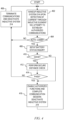
- FIG. 4 is a flowchart illustrating operation of the electronic control key 102 during inductive linking according to one embodiment of the present disclosure.
- the inductive system 214 is awakened upon detection of current through the inductive element 103 of the electronic control key 102, and the inductive system 214 attempts to establish authorized communications with the IPC circuitry 112 or with the access controller 104 via the IPC circuitry 112.
- the electronic control key 102 (or other inductive device) is first detected by the sensor 110 (or the IPC circuitry 112) and the access controller 104 is awakened to attempt to establish communications.
- the access controller 104 awakens the IPC circuitry 112 (if not already activated) to begin providing power via the inductive element 105.
- the current through the inductive element 105 induces current through the inductive element 103 awakening the inductive system 214.
- the inductive system 214 begins to establish authorized communications with the IPC circuitry 112 or with the access controller 104 via the IPC circuitry 112.
- Authorized communications may be established according to any known methods, such as including secure cryptographic and key store functions or the like. If authorized communications are not established, such as when the electronic control key 102 is attempting to communicate with another system with which it is not authorized, then operation advances to block 406 in which the communications are terminated and the inductive system 214 is deactivated. Operation then loops back to block 402 in which the inductive system 214 remains asleep until subsequently awakened.
- operation advances instead to block 408 in which the inductive system 214 queries BSTAT to determine the status of the battery 208. It is noted at this point that authorized communications may actually be established between the electronic control key 102 and the vehicle 106 during an attack scenario as shown and described in FIG. 3 since authorized communications are relayed by the first and second attack equipment 308 and 314. Nonetheless, the authorized functions are not yet enabled by the electronic control key 102. Operation then advances to block 410 to query the battery status. If BSTAT indicates that the battery status is GOOD, meaning that the battery 208 is present and sufficiently charged for normal operation, then operation advances to block 412 in which the inductive system 214 communicates with the DIST circuitry 204 to perform a secure distance check.
- next block 414 it is queried whether the secure distance check passed or failed. If the secure distance check failed (e.g., PASS is false), meaning that the electronic control key 102 is located beyond the predetermined threshold distance 101 from the vehicle 106, then an attack scenario is presumed and operation loops back to block 406 in which the communications are terminated and the inductive system 214 is deactivated as previously described. In this case, the attack scenario is thwarted.
- the secure distance check failed (e.g., PASS is false), meaning that the electronic control key 102 is located beyond the predetermined threshold distance 101 from the vehicle 106, then an attack scenario is presumed and operation loops back to block 406 in which the communications are terminated and the inductive system 214 is deactivated as previously described. In this case, the attack scenario is thwarted.
- the secure distance check passed as determined at block 414 (e.g., PASS is true), meaning that the electronic control key 102 is located within the predetermined threshold distance 101 from the vehicle 106, then operation advances instead to block 416 in which the authorized functions are enabled by the inductive system 214, the current communication session is completed, and then the inductive system 214 is deactivated and put back to sleep. Operation is completed and may loop back to block 402 previously described. In this case the electronic control key 102 is nearby and the authorized user 302 may be using the inductive link even when the status of the battery 208 is good.
- the secure distance check passed as determined at block 414 e.g., PASS is true
- BSTAT instead indicates that the battery status is NOT GOOD, meaning that the battery 208 is either not present or is not sufficiently charged for normal operation
- FIG. 5 is a simplified schematic and block diagram of circuitry of an electronic control key 502 implemented according to another embodiment of the present disclosure.
- the electronic control key 502 is substantially similar to the electronic control key 102 in which similar components include identical reference numbers.
- the COM circuitry 202, the DIST circuitry 204, and the MEMS circuitry 206 are included and coupled to communicate via the communication bus 212 in similar manner.
- the battery 208 is included to develop the supply voltage VDD on the power supply node 210 in similar manner, in which VDD is distributed to the COM circuitry 202, the DIST circuitry 204, and the MEMS circuitry 206.
- the battery status circuitry 216 is not shown, but may be included in an alternative embodiment.
- the electronic control key 502 includes a motion detector 504 coupled to the MEMS circuitry 206 and providing a motion signal MOT to the inductive system 214.
- the inductive system 214 operates in a similar manner as previously described, except that it is configured to monitor the MOT signal for making decisions regarding enablement of the access and control functions as further described herein.
- FIG. 6 is a simplified schematic and block diagram of circuitry of a mobile phone 602 implemented according to yet another embodiment of the present disclosure.
- the mobile phone 602 may include the motion detector 504 and the inductive system 214 that operate in a similar manner as the electronic control key 502.
- the mobile phone 602 includes a low power battery domain 604 that develops and provides the supply voltage VDD to the motion detector 504 and the inductive system 214 via a power supply node 606.
- the mobile phone 602 also includes remaining circuitry 608 coupled to the power supply node 606 which includes mobile phone circuitry not further described.
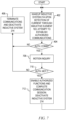
- FIG. 7 is a flowchart illustrating operation of the electronic control key 502 or the mobile phone 602 during inductive linking according to one embodiment of the present disclosure.
- the blocks 402, 404, and 406 are included and operate in substantially similar manner as previously described in FIG. 4 for the electronic control key 102.
- operation advances to block 708 in which the inductive system 214 monitors the MOT signal from the motion detector 504 to perform a motion inquiry.
- Operation then advances to block 710 in which the inductive system 214 determines whether motion of the electronic control key 502 or the mobile phone 602 is an "authorized" motion further defined herein. If the motion is not authorized, then the authorized functions are not enabled and operation loops back to block 406 in which communications are terminated and the inductive system 214 deactivated.
- an authorized motion is simply any significant motion at all, meaning that the electronic control key 502 or the mobile phone 602 is in motion.
- the inductive link 310 between the attack equipment 308 and the authorized device which in this case is with the electronic control key 502 or the mobile phone 602 is enabled only while the authorized device is stationary.
- the inductive link 310 is likely not successful while the authorized device is in motion. If the authorized device is stable and not moving as indicated by the MOT signal, then an attack scenario is presumed and authorized functions are not enabled.
- the authorized user 302 uses the authorized device, such as either the electronic control key 502 or the mobile phone 602, in the backup mode to access the vehicle 106, then the user 302 positions the authorized device within the predetermined coupling zone 108 and moves the authorized device until the authorized functions are enabled. It is noted that while the authorized device remains stationary, similar positioning and motion of the second attack equipment 314 at the vehicle 106 is not successful in enabling the authorized functions so that the attack remains unsuccessful.
- the authorized motion detected as block 708 is a predetermined, user-defined and programmable motion pattern of the authorized device, such as either the electronic control key 502 or the mobile phone 602.
- the authorized user 302 initially or preliminarily performs a motion training session by placing the authorized device in a programming mode and moves the authorized device in an arbitrary motion pattern or in any one of many different predetermined motion patterns.
- Many different types of motion patterns are contemplated, such as a circular motion including one or more circle motions in a selected direction (clockwise or counterclockwise), a figure-8 pattern, a crossing pattern, etc. Of course, other types of motions including arbitrary motions are contemplated as long as sufficiently complex.
- the authorized functions are only enabled by the inductive system 214 when the authorized device duplicates the programmed motion pattern as indicated by the MOT signal generated by the motion detector 504.
- the authorized device electronic control key 502 or mobile phone 602
- the authorized device must duplicate the programmed motion pattern rather than the second attack equipment 314.
- the attack is unsuccessful.
- FIG. 8 is a simplified block diagram of an electronic control key 802 implemented according to still another embodiment of the present disclosure.
- the electronic control key 802 includes the inductive system 214 coupled to the inductive element 103 in a similar manner previously described.
- the inductive system 214 is coupled to remaining circuitry 804 configured according the particular implementation.
- the remaining circuitry 804 may include the COM circuitry 202, the DIST circuitry 204, the MEMS circuitry 206, and the battery 208 along with any of one or more antennas and other supporting circuitry.
- the remaining circuitry 804 may include the low power domain 604 and any other remaining circuitry 608 as previously described.
- a button 806 is included and coupled to the inductive system 214.
- the button 806 may be configured in any suitable manner, such as a physical push button located on the body or chassis of the key fob or mobile phone or the like.
- the button 806 may be an existing button on the electronic control key 802 having a normal function during normal operation.
- a key fob may have a remote keyless entry (RKE) open or close button, trunk open button, etc.
- a mobile phone may have a home button, a volume button, a power button, etc.
- the existing button 806 is repurposed for a security check as further described herein.
- the button 806 may be an additional button that is dedicated to the security check.
- the user may program the inductive system 214 to sense activation or pressing of the button 806 during inductive link operation.
- FIG. 9 is a flowchart illustrating operation of the electronic control key 802 during inductive linking according to one embodiment of the present disclosure.
- the blocks 402, 404, and 406 are included and operate in substantially similar manner as previously described in FIG. 4 .
- operation advances to block 910 in which the inductive system 214 determines whether the button 806 is pressed. If the button 806 is not pressed, operation loops back to block 406 previously described in which communications are terminated and the inductive system 214 deactivated.
- operation advances to block 912 similar to blocks 416 and 712 previously described, in which the authorized functions are enabled by the inductive system 214, the current communication session is completed, and then the inductive system 214 is deactivated and put back to sleep. Operation is completed and may loop back to block 402 previously described.
- the decision to enable the authorized functions is determined by pressing of the button 806.
- the authorized user 302 needs to perform any of the authorized functions during inductive linking, then the authorized user 302 places the electronic control key 802 within the coupling zone 108 as previously described and presses the button 806.
- the attack is thwarted.
- FIG. 10 is a simplified block diagram of an electronic control key 1002 implemented according to an embodiment of the present disclosure illustrating a combination of security checks.
- the electronic control key 1002 includes the inductive system 214 coupled to the inductive element 103 in a similar manner previously described.
- the inductive system 214 is coupled to remaining circuitry 1004 configured according the particular implementation, similar to that described for the remaining circuitry 804.
- the battery status circuitry 216, the motion detector 504, and the button 806 are shown coupled to the inductive system 214. In this configuration, any one security check, or any combination of two or three security checks may be enabled.
- the inductive system 214 may check battery status via BSTAT (and perform secure distance check if GOOD) and also query MOT for authorized motion for enabling authorized functions; the inductive system 214 may check battery status via BSTAT (and perform secure distance check if GOOD) and also determine whether the button 806 is pressed for enabling authorized functions; the inductive system 214 may query MOT for authorized motion and determine whether the button 806 is pressed for enabling authorized functions; or the inductive system 214 may check battery status via BSTAT (and perform secure distance check if GOOD), query MOT for authorized motion, and determine whether the button 806 is pressed for enabling authorized functions.
- the electronic control key in any of the embodiments described herein includes security check circuitry that is incorporated within or otherwise used by an inductive system to enable authorized functions to be commanded via the inductive link. If the security check circuitry determines a potential attack, then authorized functions are not enabled and inductive link communications are terminated.
- the security check circuitry includes battery status circuitry that checks or otherwise evaluates the status of the battery of the electronic control key and that reports the status to the inductive system. If the battery is good, such as being sufficiently charged, then the inductive system forces distance measurement circuitry to perform a secure distance check to determine whether the electronic control key is within a predetermined threshold distance. If the electronic control key is not within the predetermined threshold distance, then the secure distance check fails so that the authorized functions are not enabled and inductive link communications are terminated.
- the security check circuitry includes a motion detector that reports motion to the inductive system.
- the inductive system evaluates motion of the electronic control key to determine whether an authorized motion is detected for determining whether to enable the authorized functions.
- the authorized motion may simply be any type of motion that indicates that the electronic control key is moving. If the electronic control key is not moving, then the motion test fails so that the authorized functions are not enabled and inductive link communications are terminated.
- the authorized motion is a predetermined or preprogrammed motion pattern created, chosen or otherwise selected by an authorized user. If the electronic control key does not move in accordance with the selected or programmed authorized motion pattern, then the motion test fails so that the authorized functions are not enabled and inductive link communications are terminated.
- the security check circuitry includes a button detected by the inductive system.
- the inductive system determines whether the button is pressed to determine whether to enable the authorized functions.
- a combination of security check circuitry may be included and selectively enabled.
- an electronic control key including security check circuitry used by an inductive system to perform at least one security check to determine whether to enable authorized functions.
- the inductive system receives power and enables communications via an inductive link for backup operation.
- the security check circuitry may include battery status circuitry and distance measurement circuitry.
- the inductive system invokes the distance measurement circuitry to perform a secure distance check when the battery status is good, in which the inductive system enables authorized functions only when the secure distance check passes.
- the security check circuitry may include a motion detector for performing a motion inquiry.
- the motion inquiry may include detecting motion of the electronic control key or detecting a predetermined characteristic movement or a programmed motion pattern.
- the security check circuitry may be a button in which authorized functions are enabled only when the button is pressed.
Landscapes
- Physics & Mathematics (AREA)
- General Physics & Mathematics (AREA)
- Engineering & Computer Science (AREA)
- Computer Networks & Wireless Communication (AREA)
- Computer Security & Cryptography (AREA)
- Computer Hardware Design (AREA)
- Computing Systems (AREA)
- General Engineering & Computer Science (AREA)
- Signal Processing (AREA)
- Lock And Its Accessories (AREA)
Claims (13)
- Elektronischer Steuerschlüssel (102), der Folgendes umfasst:eine induktive Verbindung;ein induktives System (214), das dafür ausgebildet ist, Energie zu empfangen und die Kommunikation über die induktive Verbindung zu ermöglichen; undeine Sicherheitskontrollschaltung, die mit dem induktiven System (214) gekoppelt und dafür ausgebildet ist, mindestens eine Sicherheitskontrolle durchzuführen, um zu bestimmen, ob autorisierte Funktionen aktiviert werden sollen, wobeidie Sicherheitskontrollschaltung Folgendes umfasst:eine Batteriestatusschaltung (216), die dafür ausgebildet ist, einen Status einer Batterie (208) anzuzeigen; undeine Abstandsmessungsschaltung (204), die dafür ausgebildet ist, eine sichere Abstandsprüfung durch eine Abstandsmessung zwischen dem elektronischen Steuerschlüssel und einem Zugangssystem durchzuführen; undwobei das induktive System (214) die Abstandsmessungsschaltung (204) aufruft, um die sichere Abstandsprüfung durchzuführen, wenn die Batteriestatusschaltung (216) anzeigt, dass der Batteriestatus gut ist, und autorisierte Funktionen nur dann freigibt, wenn die sichere Abstandsprüfung erfolgreich war.
- Elektronischer Steuerschlüssel (102) nach Anspruch 1, wobei die Abstandsmessungsschaltung (204) eine drahtlose Ultrabreitband-Kommunikationsschaltung umfasst.
- Elektronischer Steuerschlüssel (102) nach einem der vorhergehenden Ansprüche, wobeidie Sicherheitskontrollschaltung einen Bewegungsdetektor (504) umfasst; undwobei das induktive System (214) den Detektor überwacht, um eine Bewegungsabfrage durchzuführen, und die autorisierten Funktionen freigibt, wenn die Bewegungsabfrage erfolgreich war.
- Elektronischer Steuerschlüssel (102) nach Anspruch 3, wobei die Bewegungsabfrage die erkannte Bewegung des elektronischen Steuerschlüssels umfasst.
- Elektronischer Steuerschlüssel (102) nach Anspruch 3 oder 4, wobei die Bewegungsabfrage den Vergleich der von dem Bewegungsdetektor (504) erkannten Bewegung mit einer vorgegebenen charakteristischen Bewegung des elektronischen Steuerschlüssels umfasst.
- Elektronischer Steuerschlüssel (102) nach einem der Ansprüche 3 bis 5, wobei die Bewegungsabfrage das Vergleichen der Bewegung des elektronischen Steuerschlüssels mit einem programmierten Bewegungsmuster umfasst.
- Elektronischer Steuerschlüssel (102) nach einem der vorhergehenden Ansprüche, wobeidie Sicherheitskontrollschaltung eine Taste (806) umfasst; undwobei das induktive System (214) die zugelassenen Funktionen nur dann aktiviert, wenn die Taste gedrückt wird.
- Elektronischer Steuerschlüssel (102) nach einem der vorhergehenden Ansprüche, wobei
die Sicherheitskontrollschaltung Folgendes umfasst:eine Batteriestatusschaltung (216), die den Status einer Batterie (208) anzeigt;eine Abstandsmessungsschaltung (204), die eine sichere Abstandsprüfung durchführen kann; undeine Taste (806); undwobei das induktive System (214) die Abstandsmessungsschaltung (204) aufruft, um die sichere Abstandsprüfung durchzuführen, wenn der Batteriestatus gut ist, und wobei das induktive System (214) autorisierte Funktionen nur freigibt, wenn sowohl die sichere Abstandsprüfung bestanden als auch die Taste (806) gedrückt wird. - Elektronischer Steuerschlüssel (102) nach einem der vorhergehenden Ansprüche, wobei
die Sicherheitskontrollschaltung Folgendes umfasst:eine Taste (806); undeinen Bewegungsdetektor (504); undwobei das induktive System (214) den Bewegungsdetektor (504) überwacht, um eine Bewegungsabfrage durchzuführen, und wobei das induktive System autorisierte Funktionen nur dann freigibt, wenn die Bewegungsabfrage erfolgreich war und der Knopf (806) gedrückt wurde. - Elektronisches Steuerschlüsselsystem, das Folgendes umfasst:einen elektronischen Steuerschlüssel (102) nach einem der vorhergehenden Ansprüche; undein Zugangssystem (106), das eine induktive Energie- und Kommunikationsschaltung (112) umfasst, die induktiv mit dem induktiven System (214) des elektronischen Steuerschlüssels (102) über die induktive Verbindung koppeln kann, wenn sich die induktive Verbindung innerhalb einer vorbestimmten Kopplungszone (108) in einem Abstand zu der induktiven Energie- und Kommunikationsschaltung (112) befindet.
- Verfahren zum Betreiben eines elektronischen Steuerschlüssels mit einer Batterie und einer induktiven Verbindung, das Folgendes umfasst:Empfangen von Energie und Herstellen einer Kommunikation (402) über die induktive Verbindung;Durchführen, durch eine Sicherheitskontrollschaltung, mindestens einer Sicherheitskontrolle (408, 412) durch eine Abstandsmessung zwischen dem elektronischen Steuerschlüssel und einem Zugangssystem; wobeidas Durchführen mindestens einer Sicherheitskontrolle Folgendes umfasst:Überprüfen, durch eine Batteriestatusschaltung, des Status der Batterie (408); undAufrufen, durch ein induktives System, einer sicheren Abstandsprüfung (412) durch eine Abstandsmessungsschaltung, wenn der Batteriestatus gut ist;
undFreischalten (416), durch das induktive System, von autorisierten Funktionen nur dann, wenn jede der mindestens einen Sicherheitskontrollen bestanden wird. - Verfahren nach Anspruch 11, wobei das Durchführen mindestens einer Sicherheitskontrolle das Durchführen einer Bewegungsabfrage (708) umfasst, und wobei die autorisierten Funktionen nur dann aktiviert werden (712), wenn die Bewegungsabfrage eine autorisierte Bewegung anzeigt.
- Verfahren nach einem der Ansprüche 11 bis 12, wobei das Durchführen mindestens einer Sicherheitskontrolle das Erkennen umfasst, ob eine Taste gedrückt wurde (910), und wobei die autorisierten Funktionen (912) nur aktiviert werden, wenn die Taste gedrückt wurde.
Applications Claiming Priority (1)
| Application Number | Priority Date | Filing Date | Title |
|---|---|---|---|
| US16/836,758 US11055941B1 (en) | 2020-03-31 | 2020-03-31 | System and method of improving security during backup functionality of electronic control key |
Publications (2)
| Publication Number | Publication Date |
|---|---|
| EP3889919A1 EP3889919A1 (de) | 2021-10-06 |
| EP3889919B1 true EP3889919B1 (de) | 2025-01-08 |
Family
ID=75173062
Family Applications (1)
| Application Number | Title | Priority Date | Filing Date |
|---|---|---|---|
| EP21164143.6A Active EP3889919B1 (de) | 2020-03-31 | 2021-03-23 | System und verfahren zur verbesserung der sicherheit während der sicherungsfunktion eines elektronischen steuerschlüssels |
Country Status (3)
| Country | Link |
|---|---|
| US (1) | US11055941B1 (de) |
| EP (1) | EP3889919B1 (de) |
| CN (1) | CN113470220B (de) |
Families Citing this family (2)
| Publication number | Priority date | Publication date | Assignee | Title |
|---|---|---|---|---|
| US11380150B2 (en) * | 2020-02-04 | 2022-07-05 | Alarm.Com Incorporated | User detection |
| US11325562B1 (en) * | 2021-07-30 | 2022-05-10 | Geotab Inc. | Wire management module for a vehicle |
Family Cites Families (54)
| Publication number | Priority date | Publication date | Assignee | Title |
|---|---|---|---|---|
| US5790014A (en) * | 1997-04-21 | 1998-08-04 | Ford Motor Company | Charging a transponder in a security system |
| DE19802725C1 (de) * | 1998-01-24 | 1999-11-11 | Henkel Kgaa | Automatische Kontrolle und Steuerung von Reinigerbädern durch Alkalitätsbestimmung |
| JP2003512218A (ja) | 1999-10-01 | 2003-04-02 | シーメンス ヴィディーオー オートモーティヴ コーポレイション | 車両コマンドの安全な通信に対する中継アタックの検知 |
| EP1259403A2 (de) * | 2000-03-02 | 2002-11-27 | Siemens VDO Automotive Corporation | Passives, optisches identifizierungssystem |
| JP2002070375A (ja) * | 2000-09-05 | 2002-03-08 | Fujitsu Ltd | 電子鍵および電子鍵システム |
| KR200227883Y1 (ko) * | 2000-10-05 | 2001-06-15 | 김종해 | 보안 파일 케비넷 도어의 시건장치 |
| DE20020635U1 (de) * | 2000-11-28 | 2001-03-15 | Francotyp-Postalia AG & Co., 16547 Birkenwerder | Anordnung zur Stromversorgung für einen Sicherheitsbereich eines Gerätes |
| US6943666B2 (en) * | 2001-02-15 | 2005-09-13 | Agere Systems, Inc. | Recharging key based wireless device |
| DE10255880A1 (de) | 2002-11-29 | 2004-06-09 | Philips Intellectual Property & Standards Gmbh | Elektronisches Kommunikationssystem und Verfahren zum Erkennen einer Relais-Attacke auf dasselbe |
| DE10361115A1 (de) * | 2003-12-22 | 2005-07-21 | Daimlerchrysler Ag | Verfahren zur Fernbedienung von Türen und/oder Klappen für Fahrzeuge und zugehöriges Fernbediensystem |
| US7498768B2 (en) * | 2004-02-04 | 2009-03-03 | Volkswagen Aktiengesellschaft | Key for a vehicle |
| US7388466B2 (en) * | 2004-11-30 | 2008-06-17 | Lear Corporation | Integrated passive entry and remote keyless entry system |
| US20060223500A1 (en) * | 2005-03-31 | 2006-10-05 | Sanyo Electric Co., Ltd. | Authentication system |
| US20070090965A1 (en) * | 2005-10-21 | 2007-04-26 | Mc Call Clark E | Key-fob locating method and apparatus |
| US20080166651A1 (en) * | 2006-11-01 | 2008-07-10 | Xerox Corporation | Toner having crosslinked resin for controlling matte performance |
| US20090328189A1 (en) * | 2008-05-05 | 2009-12-31 | Gm Global Technology Operations, Inc. | Secure wireless communication initialization system and method |
| US20090291637A1 (en) * | 2008-05-21 | 2009-11-26 | Gm Global Technology Operations, Inc. | Secure wireless communication initialization system and method |
| US8587403B2 (en) * | 2009-06-18 | 2013-11-19 | Lear Corporation | Method and system of determining and preventing relay attack for passive entry system |
| US20110115605A1 (en) * | 2009-11-17 | 2011-05-19 | Strattec Security Corporation | Energy harvesting system |
| US8284020B2 (en) * | 2009-12-22 | 2012-10-09 | Lear Corporation | Passive entry system and method for a vehicle |
| US9230440B1 (en) * | 2011-04-22 | 2016-01-05 | Angel A. Penilla | Methods and systems for locating public parking and receiving security ratings for parking locations and generating notifications to vehicle user accounts regarding alerts and cloud access to security information |
| US20160129883A1 (en) * | 2011-04-22 | 2016-05-12 | Angel A. Penilla | Contact detect feature of a vehicle and notifications to enable live views of vehicle |
| US9123035B2 (en) * | 2011-04-22 | 2015-09-01 | Angel A. Penilla | Electric vehicle (EV) range extending charge systems, distributed networks of charge kiosks, and charge locating mobile apps |
| US9809196B1 (en) * | 2011-04-22 | 2017-11-07 | Emerging Automotive, Llc | Methods and systems for vehicle security and remote access and safety control interfaces and notifications |
| US8834254B2 (en) * | 2011-09-06 | 2014-09-16 | Wms Gaming, Inc. | Account-based-wagering mobile controller |
| DE102012008395A1 (de) * | 2012-04-27 | 2013-10-31 | Lock Your World Gmbh & Co. Kg | Verfahren und System für eine gesicherteSchlüssel-Übergabe |
| KR101362325B1 (ko) * | 2012-07-19 | 2014-02-13 | 현대모비스 주식회사 | 트렁크 자동 열림 제어 장치 및 방법 |
| US20140082569A1 (en) * | 2012-09-17 | 2014-03-20 | Steven Robert Borgman | Security System and Methods For Portable Devices |
| US20140176301A1 (en) * | 2012-12-20 | 2014-06-26 | Lear Corporation | Remote Function Fob for Enabling Communication Between a Vehicle and a Device and Method for Same |
| DE102014102271A1 (de) * | 2013-03-15 | 2014-09-18 | Maxim Integrated Products, Inc. | Verfahren und Einrichtung zum Erteilen einer Zutrittserlaubnis |
| US8996197B2 (en) * | 2013-06-20 | 2015-03-31 | Ford Global Technologies, Llc | Lane monitoring with electronic horizon |
| US8994498B2 (en) * | 2013-07-25 | 2015-03-31 | Bionym Inc. | Preauthorized wearable biometric device, system and method for use thereof |
| US9702970B2 (en) * | 2013-08-30 | 2017-07-11 | Maxim Integrated Products, Inc. | Time of arrival delay cancellations |
| US20150116079A1 (en) * | 2013-10-24 | 2015-04-30 | GM Global Technology Operations LLC | Enhanced vehicle key fob |
| US9747736B2 (en) * | 2014-08-05 | 2017-08-29 | Texas Instruments Deutschland Gmbh | Multiple-band identification and ranging |
| US9328531B1 (en) * | 2014-10-09 | 2016-05-03 | Everald Lloyd Smeikle | Rechargeable automobile ignition key |
| DE112014006819B4 (de) | 2014-10-15 | 2023-06-29 | Continental Automotive Technologies GmbH | Verfahren und system zum erkennen von weterleitungs-angriffen für ein passives zugangssystem |
| US9710983B2 (en) * | 2015-01-29 | 2017-07-18 | GM Global Technology Operations LLC | Method and system for authenticating vehicle equipped with passive keyless system |
| US9836896B2 (en) * | 2015-02-04 | 2017-12-05 | Proprius Technologies S.A.R.L | Keyless access control with neuro and neuro-mechanical fingerprints |
| CN106296880A (zh) * | 2015-05-25 | 2017-01-04 | 鸿富锦精密工业(深圳)有限公司 | 无线充电电子锁具 |
| US10157522B2 (en) * | 2016-04-15 | 2018-12-18 | Mobile Tech, Inc. | Authorization control for an anti-theft security system |
| NL2018466B1 (en) * | 2016-09-22 | 2018-03-29 | Bolt Mobility B V | Scooter |
| US10328898B2 (en) * | 2016-10-12 | 2019-06-25 | Denso International America, Inc. | Passive entry / passive start systems and methods for vehicles |
| EP3335942B1 (de) * | 2016-12-14 | 2019-11-20 | Nxp B.V. | Sicheres ventilzugangssystem für fahrzeug, schlüssel, fahrzeug und verfahren dafür |
| US10214221B2 (en) * | 2017-01-20 | 2019-02-26 | Honda Motor Co., Ltd. | System and method for identifying a vehicle driver by a pattern of movement |
| US10220854B2 (en) * | 2017-01-20 | 2019-03-05 | Honda Motor Co., Ltd. | System and method for identifying at least one passenger of a vehicle by a pattern of movement |
| GB2561583A (en) * | 2017-04-19 | 2018-10-24 | Jaguar Land Rover Ltd | Vehicle access system |
| JP6791048B2 (ja) * | 2017-07-25 | 2020-11-25 | トヨタ自動車株式会社 | 電子キーシステムおよび電子キーの制御方法 |
| CN111542460B (zh) * | 2017-11-20 | 2023-04-07 | 罗伯特·博世(澳大利亚)私人有限公司 | 加入运动用于防止中继攻击的方法和系统 |
| US10766458B2 (en) * | 2018-07-13 | 2020-09-08 | Nxp B.V. | Sensor fusion for passive keyless entry systems |
| US10911949B2 (en) * | 2018-07-23 | 2021-02-02 | Byton Limited | Systems and methods for a vehicle authenticating and enrolling a wireless device |
| US10440576B1 (en) * | 2018-08-23 | 2019-10-08 | Nxp B.V. | System for securing keyless entry systems |
| US11417163B2 (en) * | 2019-01-04 | 2022-08-16 | Byton North America Corporation | Systems and methods for key fob motion based gesture commands |
| US10814832B2 (en) * | 2019-02-08 | 2020-10-27 | Ford Global Technologies, Llp | Systems and methods for vehicle low power security challenge |
-
2020
- 2020-03-31 US US16/836,758 patent/US11055941B1/en active Active
-
2021
- 2021-03-23 EP EP21164143.6A patent/EP3889919B1/de active Active
- 2021-03-24 CN CN202110316735.5A patent/CN113470220B/zh active Active
Also Published As
| Publication number | Publication date |
|---|---|
| US11055941B1 (en) | 2021-07-06 |
| CN113470220A (zh) | 2021-10-01 |
| CN113470220B (zh) | 2025-03-18 |
| EP3889919A1 (de) | 2021-10-06 |
Similar Documents
| Publication | Publication Date | Title |
|---|---|---|
| US10917750B2 (en) | System and method for locating a portable device in different zones relative to a vehicle and enabling vehicle control functions | |
| EP3287331B1 (de) | Automobilsicherheitsvorrichtung und zugehörige verfahren | |
| US8774714B2 (en) | External power supply system for a lock comprising NFC-type contactless communication means | |
| CN101271600B (zh) | 运输工具用的访问装置 | |
| CN104870267B (zh) | 用于机动车的被动进入系统以及所属的方法 | |
| CN112365632A (zh) | 车辆进入隐私模式的nfc激活 | |
| US10723316B2 (en) | Locking and unlocking system | |
| JP2017014834A (ja) | 電子キー及び電子キーシステム | |
| EP3889919B1 (de) | System und verfahren zur verbesserung der sicherheit während der sicherungsfunktion eines elektronischen steuerschlüssels | |
| KR20190081118A (ko) | 차량 제어 장치 및 방법 | |
| CN110546046A (zh) | 用于控制对车辆的访问的按钮配件设备 | |
| EP3889917B1 (de) | System und verfahren zur optimierten backup-funktionalität für elektronischen steuerschlüssel | |
| KR102601172B1 (ko) | 차량 원격 제어를 위한 스마트키 제어 방법 및 시스템 | |
| CN108700419A (zh) | 用于微定位便携式车辆控制设备并与其通信的系统和方法 | |
| CN110001573A (zh) | 根据不同策略控制取用车辆的方法 | |
| JP2019071198A (ja) | スイッチ装置 | |
| JP6702840B2 (ja) | 無線通信正否判定システム | |
| JP6471034B2 (ja) | ドア作動制御システム | |
| US11438028B2 (en) | Communication set-up for wireless communication and method for controlling such a communication set-up | |
| JP2012184609A (ja) | キーレスエントリー装置 | |
| JP2019085777A (ja) | 電子キー及び電子キーシステム | |
| KR20180136784A (ko) | 초음파와 무선신호를 이용한 도어락 시스템 | |
| JP2016117994A (ja) | キーインロックシステム | |
| WO2019192630A1 (en) | Method for securing passive keyless systems and equipment therefor | |
| HK1262850A1 (en) | System and method for micro-locating and communicating with a portable vehicle control device |
Legal Events
| Date | Code | Title | Description |
|---|---|---|---|
| PUAI | Public reference made under article 153(3) epc to a published international application that has entered the european phase |
Free format text: ORIGINAL CODE: 0009012 |
|
| STAA | Information on the status of an ep patent application or granted ep patent |
Free format text: STATUS: THE APPLICATION HAS BEEN PUBLISHED |
|
| AK | Designated contracting states |
Kind code of ref document: A1 Designated state(s): AL AT BE BG CH CY CZ DE DK EE ES FI FR GB GR HR HU IE IS IT LI LT LU LV MC MK MT NL NO PL PT RO RS SE SI SK SM TR |
|
| STAA | Information on the status of an ep patent application or granted ep patent |
Free format text: STATUS: REQUEST FOR EXAMINATION WAS MADE |
|
| 17P | Request for examination filed |
Effective date: 20220406 |
|
| RBV | Designated contracting states (corrected) |
Designated state(s): AL AT BE BG CH CY CZ DE DK EE ES FI FR GB GR HR HU IE IS IT LI LT LU LV MC MK MT NL NO PL PT RO RS SE SI SK SM TR |
|
| STAA | Information on the status of an ep patent application or granted ep patent |
Free format text: STATUS: EXAMINATION IS IN PROGRESS |
|
| 17Q | First examination report despatched |
Effective date: 20240612 |
|
| 17Q | First examination report despatched |
Effective date: 20240626 |
|
| GRAP | Despatch of communication of intention to grant a patent |
Free format text: ORIGINAL CODE: EPIDOSNIGR1 |
|
| STAA | Information on the status of an ep patent application or granted ep patent |
Free format text: STATUS: GRANT OF PATENT IS INTENDED |
|
| INTG | Intention to grant announced |
Effective date: 20240917 |
|
| GRAS | Grant fee paid |
Free format text: ORIGINAL CODE: EPIDOSNIGR3 |
|
| GRAA | (expected) grant |
Free format text: ORIGINAL CODE: 0009210 |
|
| STAA | Information on the status of an ep patent application or granted ep patent |
Free format text: STATUS: THE PATENT HAS BEEN GRANTED |
|
| AK | Designated contracting states |
Kind code of ref document: B1 Designated state(s): AL AT BE BG CH CY CZ DE DK EE ES FI FR GB GR HR HU IE IS IT LI LT LU LV MC MK MT NL NO PL PT RO RS SE SI SK SM TR |
|
| REG | Reference to a national code |
Ref country code: GB Ref legal event code: FG4D |
|
| REG | Reference to a national code |
Ref country code: CH Ref legal event code: EP |
|
| REG | Reference to a national code |
Ref country code: DE Ref legal event code: R096 Ref document number: 602021024554 Country of ref document: DE |
|
| REG | Reference to a national code |
Ref country code: IE Ref legal event code: FG4D |
|
| PGFP | Annual fee paid to national office [announced via postgrant information from national office to epo] |
Ref country code: DE Payment date: 20250218 Year of fee payment: 5 |
|
| PGFP | Annual fee paid to national office [announced via postgrant information from national office to epo] |
Ref country code: AT Payment date: 20250417 Year of fee payment: 5 |
|
| PGFP | Annual fee paid to national office [announced via postgrant information from national office to epo] |
Ref country code: FR Payment date: 20250218 Year of fee payment: 5 |
|
| REG | Reference to a national code |
Ref country code: LT Ref legal event code: MG9D |
|
| REG | Reference to a national code |
Ref country code: NL Ref legal event code: MP Effective date: 20250108 |
|
| REG | Reference to a national code |
Ref country code: AT Ref legal event code: MK05 Ref document number: 1758855 Country of ref document: AT Kind code of ref document: T Effective date: 20250108 |
|
| PG25 | Lapsed in a contracting state [announced via postgrant information from national office to epo] |
Ref country code: NL Free format text: LAPSE BECAUSE OF FAILURE TO SUBMIT A TRANSLATION OF THE DESCRIPTION OR TO PAY THE FEE WITHIN THE PRESCRIBED TIME-LIMIT Effective date: 20250108 |
|
| PG25 | Lapsed in a contracting state [announced via postgrant information from national office to epo] |
Ref country code: RS Free format text: LAPSE BECAUSE OF FAILURE TO SUBMIT A TRANSLATION OF THE DESCRIPTION OR TO PAY THE FEE WITHIN THE PRESCRIBED TIME-LIMIT Effective date: 20250408 |
|
| PG25 | Lapsed in a contracting state [announced via postgrant information from national office to epo] |
Ref country code: FI Free format text: LAPSE BECAUSE OF FAILURE TO SUBMIT A TRANSLATION OF THE DESCRIPTION OR TO PAY THE FEE WITHIN THE PRESCRIBED TIME-LIMIT Effective date: 20250108 |
|
| PG25 | Lapsed in a contracting state [announced via postgrant information from national office to epo] |
Ref country code: PL Free format text: LAPSE BECAUSE OF FAILURE TO SUBMIT A TRANSLATION OF THE DESCRIPTION OR TO PAY THE FEE WITHIN THE PRESCRIBED TIME-LIMIT Effective date: 20250108 |
|
| PG25 | Lapsed in a contracting state [announced via postgrant information from national office to epo] |
Ref country code: ES Free format text: LAPSE BECAUSE OF FAILURE TO SUBMIT A TRANSLATION OF THE DESCRIPTION OR TO PAY THE FEE WITHIN THE PRESCRIBED TIME-LIMIT Effective date: 20250108 |
|
| PG25 | Lapsed in a contracting state [announced via postgrant information from national office to epo] |
Ref country code: NO Free format text: LAPSE BECAUSE OF FAILURE TO SUBMIT A TRANSLATION OF THE DESCRIPTION OR TO PAY THE FEE WITHIN THE PRESCRIBED TIME-LIMIT Effective date: 20250408 Ref country code: IS Free format text: LAPSE BECAUSE OF FAILURE TO SUBMIT A TRANSLATION OF THE DESCRIPTION OR TO PAY THE FEE WITHIN THE PRESCRIBED TIME-LIMIT Effective date: 20250508 |
|
| PG25 | Lapsed in a contracting state [announced via postgrant information from national office to epo] |
Ref country code: HR Free format text: LAPSE BECAUSE OF FAILURE TO SUBMIT A TRANSLATION OF THE DESCRIPTION OR TO PAY THE FEE WITHIN THE PRESCRIBED TIME-LIMIT Effective date: 20250108 |
|
| PG25 | Lapsed in a contracting state [announced via postgrant information from national office to epo] |
Ref country code: LV Free format text: LAPSE BECAUSE OF FAILURE TO SUBMIT A TRANSLATION OF THE DESCRIPTION OR TO PAY THE FEE WITHIN THE PRESCRIBED TIME-LIMIT Effective date: 20250108 Ref country code: PT Free format text: LAPSE BECAUSE OF FAILURE TO SUBMIT A TRANSLATION OF THE DESCRIPTION OR TO PAY THE FEE WITHIN THE PRESCRIBED TIME-LIMIT Effective date: 20250508 |
|
| PG25 | Lapsed in a contracting state [announced via postgrant information from national office to epo] |
Ref country code: BG Free format text: LAPSE BECAUSE OF FAILURE TO SUBMIT A TRANSLATION OF THE DESCRIPTION OR TO PAY THE FEE WITHIN THE PRESCRIBED TIME-LIMIT Effective date: 20250108 Ref country code: GR Free format text: LAPSE BECAUSE OF FAILURE TO SUBMIT A TRANSLATION OF THE DESCRIPTION OR TO PAY THE FEE WITHIN THE PRESCRIBED TIME-LIMIT Effective date: 20250409 |
|
| PG25 | Lapsed in a contracting state [announced via postgrant information from national office to epo] |
Ref country code: AT Free format text: LAPSE BECAUSE OF FAILURE TO SUBMIT A TRANSLATION OF THE DESCRIPTION OR TO PAY THE FEE WITHIN THE PRESCRIBED TIME-LIMIT Effective date: 20250108 |
|
| PG25 | Lapsed in a contracting state [announced via postgrant information from national office to epo] |
Ref country code: SE Free format text: LAPSE BECAUSE OF FAILURE TO SUBMIT A TRANSLATION OF THE DESCRIPTION OR TO PAY THE FEE WITHIN THE PRESCRIBED TIME-LIMIT Effective date: 20250108 |
|
| PG25 | Lapsed in a contracting state [announced via postgrant information from national office to epo] |
Ref country code: SM Free format text: LAPSE BECAUSE OF FAILURE TO SUBMIT A TRANSLATION OF THE DESCRIPTION OR TO PAY THE FEE WITHIN THE PRESCRIBED TIME-LIMIT Effective date: 20250108 |
|
| REG | Reference to a national code |
Ref country code: DE Ref legal event code: R097 Ref document number: 602021024554 Country of ref document: DE |
|
| PG25 | Lapsed in a contracting state [announced via postgrant information from national office to epo] |
Ref country code: DK Free format text: LAPSE BECAUSE OF FAILURE TO SUBMIT A TRANSLATION OF THE DESCRIPTION OR TO PAY THE FEE WITHIN THE PRESCRIBED TIME-LIMIT Effective date: 20250108 |
|
| PG25 | Lapsed in a contracting state [announced via postgrant information from national office to epo] |
Ref country code: MC Free format text: LAPSE BECAUSE OF FAILURE TO SUBMIT A TRANSLATION OF THE DESCRIPTION OR TO PAY THE FEE WITHIN THE PRESCRIBED TIME-LIMIT Effective date: 20250108 |
|
| PG25 | Lapsed in a contracting state [announced via postgrant information from national office to epo] |
Ref country code: CZ Free format text: LAPSE BECAUSE OF FAILURE TO SUBMIT A TRANSLATION OF THE DESCRIPTION OR TO PAY THE FEE WITHIN THE PRESCRIBED TIME-LIMIT Effective date: 20250108 Ref country code: EE Free format text: LAPSE BECAUSE OF FAILURE TO SUBMIT A TRANSLATION OF THE DESCRIPTION OR TO PAY THE FEE WITHIN THE PRESCRIBED TIME-LIMIT Effective date: 20250108 |
|
| PG25 | Lapsed in a contracting state [announced via postgrant information from national office to epo] |
Ref country code: RO Free format text: LAPSE BECAUSE OF FAILURE TO SUBMIT A TRANSLATION OF THE DESCRIPTION OR TO PAY THE FEE WITHIN THE PRESCRIBED TIME-LIMIT Effective date: 20250108 |
|
| REG | Reference to a national code |
Ref country code: CH Ref legal event code: H13 Free format text: ST27 STATUS EVENT CODE: U-0-0-H10-H13 (AS PROVIDED BY THE NATIONAL OFFICE) Effective date: 20251023 |
|
| PG25 | Lapsed in a contracting state [announced via postgrant information from national office to epo] |
Ref country code: SK Free format text: LAPSE BECAUSE OF FAILURE TO SUBMIT A TRANSLATION OF THE DESCRIPTION OR TO PAY THE FEE WITHIN THE PRESCRIBED TIME-LIMIT Effective date: 20250108 |
|
| PLBE | No opposition filed within time limit |
Free format text: ORIGINAL CODE: 0009261 |
|
| STAA | Information on the status of an ep patent application or granted ep patent |
Free format text: STATUS: NO OPPOSITION FILED WITHIN TIME LIMIT |
|
| PG25 | Lapsed in a contracting state [announced via postgrant information from national office to epo] |
Ref country code: LU Free format text: LAPSE BECAUSE OF NON-PAYMENT OF DUE FEES Effective date: 20250323 |
|
| REG | Reference to a national code |
Ref country code: BE Ref legal event code: MM Effective date: 20250331 |
|
| 26N | No opposition filed |
Effective date: 20251009 |
|
| GBPC | Gb: european patent ceased through non-payment of renewal fee |
Effective date: 20250408 |
|
| PG25 | Lapsed in a contracting state [announced via postgrant information from national office to epo] |
Ref country code: GB Free format text: LAPSE BECAUSE OF NON-PAYMENT OF DUE FEES Effective date: 20250408 |
|
| PG25 | Lapsed in a contracting state [announced via postgrant information from national office to epo] |
Ref country code: BE Free format text: LAPSE BECAUSE OF NON-PAYMENT OF DUE FEES Effective date: 20250331 |
|
| PG25 | Lapsed in a contracting state [announced via postgrant information from national office to epo] |
Ref country code: CH Free format text: LAPSE BECAUSE OF NON-PAYMENT OF DUE FEES Effective date: 20250331 |
|
| PG25 | Lapsed in a contracting state [announced via postgrant information from national office to epo] |
Ref country code: IE Free format text: LAPSE BECAUSE OF NON-PAYMENT OF DUE FEES Effective date: 20250323 |
|
| PG25 | Lapsed in a contracting state [announced via postgrant information from national office to epo] |
Ref country code: IT Free format text: LAPSE BECAUSE OF FAILURE TO SUBMIT A TRANSLATION OF THE DESCRIPTION OR TO PAY THE FEE WITHIN THE PRESCRIBED TIME-LIMIT Effective date: 20250108 |