EP3889639B1 - Entfernungsmessungssensor, fahrzeugleuchte und entfernungsmessverfahren - Google Patents
Entfernungsmessungssensor, fahrzeugleuchte und entfernungsmessverfahren Download PDFInfo
- Publication number
- EP3889639B1 EP3889639B1 EP19889042.8A EP19889042A EP3889639B1 EP 3889639 B1 EP3889639 B1 EP 3889639B1 EP 19889042 A EP19889042 A EP 19889042A EP 3889639 B1 EP3889639 B1 EP 3889639B1
- Authority
- EP
- European Patent Office
- Prior art keywords
- distance
- distance measurement
- measurement sensor
- light
- obj
- Prior art date
- Legal status (The legal status is an assumption and is not a legal conclusion. Google has not performed a legal analysis and makes no representation as to the accuracy of the status listed.)
- Active
Links
Images


Classifications
-
- G—PHYSICS
- G01—MEASURING; TESTING
- G01S—RADIO DIRECTION-FINDING; RADIO NAVIGATION; DETERMINING DISTANCE OR VELOCITY BY USE OF RADIO WAVES; LOCATING OR PRESENCE-DETECTING BY USE OF THE REFLECTION OR RERADIATION OF RADIO WAVES; ANALOGOUS ARRANGEMENTS USING OTHER WAVES
- G01S17/00—Systems using the reflection or reradiation of electromagnetic waves other than radio waves, e.g. lidar systems
- G01S17/02—Systems using the reflection of electromagnetic waves other than radio waves
- G01S17/06—Systems determining position data of a target
- G01S17/08—Systems determining position data of a target for measuring distance only
-
- G—PHYSICS
- G01—MEASURING; TESTING
- G01S—RADIO DIRECTION-FINDING; RADIO NAVIGATION; DETERMINING DISTANCE OR VELOCITY BY USE OF RADIO WAVES; LOCATING OR PRESENCE-DETECTING BY USE OF THE REFLECTION OR RERADIATION OF RADIO WAVES; ANALOGOUS ARRANGEMENTS USING OTHER WAVES
- G01S17/00—Systems using the reflection or reradiation of electromagnetic waves other than radio waves, e.g. lidar systems
- G01S17/02—Systems using the reflection of electromagnetic waves other than radio waves
- G01S17/06—Systems determining position data of a target
- G01S17/42—Simultaneous measurement of distance and other co-ordinates
-
- G—PHYSICS
- G01—MEASURING; TESTING
- G01S—RADIO DIRECTION-FINDING; RADIO NAVIGATION; DETERMINING DISTANCE OR VELOCITY BY USE OF RADIO WAVES; LOCATING OR PRESENCE-DETECTING BY USE OF THE REFLECTION OR RERADIATION OF RADIO WAVES; ANALOGOUS ARRANGEMENTS USING OTHER WAVES
- G01S17/00—Systems using the reflection or reradiation of electromagnetic waves other than radio waves, e.g. lidar systems
- G01S17/88—Lidar systems specially adapted for specific applications
- G01S17/93—Lidar systems specially adapted for specific applications for anti-collision purposes
- G01S17/931—Lidar systems specially adapted for specific applications for anti-collision purposes of land vehicles
-
- G—PHYSICS
- G01—MEASURING; TESTING
- G01S—RADIO DIRECTION-FINDING; RADIO NAVIGATION; DETERMINING DISTANCE OR VELOCITY BY USE OF RADIO WAVES; LOCATING OR PRESENCE-DETECTING BY USE OF THE REFLECTION OR RERADIATION OF RADIO WAVES; ANALOGOUS ARRANGEMENTS USING OTHER WAVES
- G01S7/00—Details of systems according to groups G01S13/00, G01S15/00, G01S17/00
- G01S7/48—Details of systems according to groups G01S13/00, G01S15/00, G01S17/00 of systems according to group G01S17/00
- G01S7/481—Constructional features, e.g. arrangements of optical elements
- G01S7/4817—Constructional features, e.g. arrangements of optical elements relating to scanning
-
- G—PHYSICS
- G02—OPTICS
- G02B—OPTICAL ELEMENTS, SYSTEMS OR APPARATUS
- G02B26/00—Optical devices or arrangements for the control of light using movable or deformable optical elements
- G02B26/08—Optical devices or arrangements for the control of light using movable or deformable optical elements for controlling the direction of light
- G02B26/0816—Optical devices or arrangements for the control of light using movable or deformable optical elements for controlling the direction of light by means of one or more reflecting elements
-
- G—PHYSICS
- G02—OPTICS
- G02B—OPTICAL ELEMENTS, SYSTEMS OR APPARATUS
- G02B26/00—Optical devices or arrangements for the control of light using movable or deformable optical elements
- G02B26/08—Optical devices or arrangements for the control of light using movable or deformable optical elements for controlling the direction of light
- G02B26/10—Scanning systems
- G02B26/105—Scanning systems with one or more pivoting mirrors or galvano-mirrors
-
- G—PHYSICS
- G02—OPTICS
- G02B—OPTICAL ELEMENTS, SYSTEMS OR APPARATUS
- G02B26/00—Optical devices or arrangements for the control of light using movable or deformable optical elements
- G02B26/08—Optical devices or arrangements for the control of light using movable or deformable optical elements for controlling the direction of light
- G02B26/10—Scanning systems
- G02B26/12—Scanning systems using multifaceted mirrors
- G02B26/121—Mechanical drive devices for polygonal mirrors
- G02B26/122—Control of the scanning speed of the polygonal mirror
Definitions
- the present invention relates to a distance measurement technique.
- LiDAR Light Detection and Ranging
- Laser Imaging Detection and Ranging LiDAR
- advantages include: (i) an advantage of being capable of recognizing an object based on point cloud data; (ii) an advantage in employing active sensing, which is capable of providing high-precision detection even in bad weather conditions; (iii) an advantage of providing wide-range measurement; etc. Accordingly, LiDAR is anticipated to become mainstream in vehicle sensing systems.
- the present invention has been made in view of such a situation. Accordingly, it is an exemplary purpose of an embodiment of the present invention to provide a distance measurement sensor with a reduced cost while suppressing degradation in object detection precision.
- An embodiment of the present invention relates to a distance measurement sensor.
- the distance measurement sensor includes: a light source; a scanning device including a motor and a mirror attached to the motor and structured to reflect emitted light of the light source, in which the scanning device is structured such that scan probe light, which is light reflected by the mirror, can be scanned according to the rotation of the motor; a photosensor structured to detect during a scan period return light, which is the probe light reflected by an object; and a processor structured to detect the distance to a point on the object based on the output of the photosensor.
- the angular resolution in the scan direction is changed dynamically according to the distance to the point on the object during the scan period.
- a measurement sensor can be provided with a reduced cost while suppressing degradation in object detection precision.
- the distance measurement sensor includes a light source, a scanning device, a photosensor, and a processor.
- the scanning device includes a motor and a mirror attached to the motor and structured to reflect emitted light of the light source.
- the scanning device is structured such that scan probe light, which is light reflected by the mirror, can be scanned according to the rotation of the motor.
- the photosensor detects during a scan period return light that is the probe light reflected from a point on an object.
- the angular resolution in the scan direction is dynamically changed according to the distance tc the point on the object during the scan period.
- the resolution in the scan direction (e.g., horizontal direction) is dynamically changed according to the distance to the object. This allows the shape of an object located at a farther position to be detected with high precision.
- the rotational speed of the motor may be changed according to the distance to the object.
- the distance measurement period may be changed according to the distance to the object.
- the automotive lamp includes: any one from among the above-described distance measurement sensors; a variable light distribution lamp; and a controller structured to control the variable light distribution lamp according to the output of the distance measurement sensor.
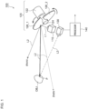
- Fig. 1 is a block diagram showing a distance measurement sensor 100 according to an embodiment.
- the distance measurement sensor 100 is configured as a LiDAR (Light Detection and Ranging), including a light source 110, a scanning device 120, a photosensor 130, and a processor 140.
- the light source 110 emits light L1 having an infrared spectrum, for example.
- the emitted light L1 of the light source 110 may be modulated with respect to time.
- the scanning device 120 includes a motor 122 and one or multiple mirrors (which will be also referred to as "blades") 126.
- the mirrors 126 are configured to have a fan-shaped structure.
- the mirrors 126 are attached to a rotational shaft 124 of the motor 122 such that they reflect the emitted light L1 of the light source 110.
- the emission angle (which will also be referred to as a "scan angle") ⁇ of probe light L2 which is light reflected from the mirrors 126, changes according to the position of the mirrors 126 (i.e., rotational angle ⁇ of the motor). Accordingly, by rotationally driving the motor 122, the probe light L2 can be scanned in the ⁇ direction ranging between ⁇ MIN and ⁇ MAX .
- the number of mirrors 126 thus provided is two, one half-rotation of the motor 122 (mechanical angle of 180 degrees) corresponds to a single scan. Accordingly, the probe light L2 is scanned twice every time the motor 122 is rotated once. It should be noted that the number of the mirrors 126 is not restricted in particular.
- the rotational angle ⁇ of the motor 122 can be detected by means of a position detection mechanism such as a Hall sensor, optical encoder, or the like. Accordingly, the scan angle ⁇ at each time point can be obtained based on the rotational angle ⁇ .
- the photosensor 130 detects return light L3 reflected at a point P on an object OBJ.
- the processor 140 detects the distance to the point P on the object OBJ based on the output of the photosensor 130.
- the distance detection method or algorithm is not restricted in particular. Rather, known techniques may be employed. For example, the delay time from the emission of the probe light L2 to the reception of the return light by means of the photosensor 130, i.e., the time of flight (TOF), may be measured so as to acquire the distance.
- TOF time of flight
- the above is the basic configuration of the distance measurement sensor 100. Next, description will be made regarding the operation thereof.
- the motor 122 is rotationally driven so as to change the scan angle ⁇ of the probe light L2 in the order of ⁇ 1 , ⁇ 2 , ....
- data point cloud data formed of data pairs each configured as a pair of the scan angle ⁇ i and the corresponding distance r i , can be acquired.
- the scanning device 120 can be configured as a combination of the motor 122 configured as a commonplace motor and the mirrors 126 arranged in a fan structure. This provides the distance measurement sensor 100 with a reduced cost.
- FIG. 2 is a diagram showing the point cloud data acquired in measurement with a constant angular resolution ⁇ .
- An object OBJ1 is located at a position that is relatively nearer to the distance measurement sensor 100.
- an object OBJ2 is located at a position that is relatively farther from the distance measurement sensor 100.
- reflected light data is acquired for a relatively larger number of points P1 with respect to the object OBJ1 at a position nearer to the distance measurement sensor 100.
- the number of the points P for which the reflected light data is acquired becomes smaller. That is to say, as the distance to the object becomes larger, the difficulty of judging its shape becomes higher.
- the angular resolution ⁇ is designed to be very fine so as to provide sufficient resolution for an object at the farthest position within the distance measurement range of the distance measurement sensor 100.
- such an approach involves an enormous number of points of point cloud data acquired in a single scan. This requires the processor 140 to support an enormous amount of calculation, leading to reduction of the scanning rate.
- the processor 140 In order to provide the scanning rate required by an application, such an arrangement requires the processor 140 to be configured as a high-cost, high-performance processor. This does not meet a demand for the distance measurement sensor 100 to be provided with a low cost.
- the angular resolution ⁇ is designed to be dynamically changed according to the distance d to the object OBJ.
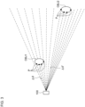
- Fig. 3 is a diagram showing the point cloud data acquired with a variable angular resolution ⁇ .
- the angular resolution ⁇ is adjusted to a higher resolution.
- reflected light data is acquired for four points with respect to the object OBJ2 at a farther position. This allows the shape judgement to be made even for the object OBJ2 located at a farther position.
- the angular resolution ⁇ is adjusted to a lower resolution so as to reduce the number of points of point cloud data. This allows the scanning rate required for an application to be supported even in a case of employing a low-cost, relatively low-performance processor as the processor 140.
- Figs. 4A and 4B are diagrams each showing the relation between the distance d to the object and the angular resolution ⁇ .
- a spatial resolution of ⁇ x is designed in the scan direction regardless of the distance d to the object.
- Expression (1) it is sufficient if the following Expression (1) is satisfied. Accordingly, the relation expression between ⁇ and d is represented by Expression (2).
- Figs. 4A and 4B are diagrams each showing the relation between ⁇ and d with ⁇ x as 0.2 m. Specifically, Fig. 4 shows the relation with the horizontal axis as a linear scale. Fig. 4B shows the relation with the horizontal axis as a logarithmic scale.
- the angular resolution ⁇ may be held in the form of a function of the distance d, and the angular resolution ⁇ may be calculated by the processor 140.
- a table that represents the relation between the distance d and the angular resolution ⁇ may be held, and the angular resolution ⁇ may be acquired by referring to the table.
- the angular resolution ⁇ may be changed in a discrete manner as described below. That is to say, the overall distance measurement range is divided into m multiple ranges R 1 through R m , and the angular resolutions ⁇ 1 through ⁇ m may be determined for each range.
- Fig. 5 is a diagram showing the relation between the distance measurement range and the angular resolution ⁇ .
- the number of the divided ranges is not restricted in particular.
- the division number m may be 2 or 4 or more.
- the distance d to the object OBJ can be detected based on the distance r to a typical point P on the surface of the object OBJ.
- the typical point the point at which the reflected light data was first acquired may be selected.
- multiple points may be selected as the typical points.
- the average value of the distances to the multiple typical points may be employed as the distance d to the object OBJ.
- the resolution ⁇ is dynamically changed in one scanning period.
- the angular resolution ⁇ may be updated every time a new object OBJ is detected.
- Fig. 6 is a diagram showing an example of the control of the angular resolution ⁇ .
- the horizontal axis represents the scan angle ⁇ , which can be associated with the direction of time progression.
- the upper graph shows the distance r.
- the lower graph shows the angular resolution ⁇ .
- Fig. 6 shows graphs over two scanning periods.
- the angular resolution ⁇ is set to an initial value ⁇ 0 .
- the distance r i to the first point P i is measured on the object OBJ1.
- judgement is made that the object OBJ1 is positioned within the range R 1 . Accordingly, after the angular resolution ⁇ is set to a larger value ⁇ 1 , the scanning progresses.
- the distance r j to the first point P j is measured on the object OBJ2.
- judgement is made that the object OBJ2 is positioned within the range R 2 . Accordingly, after the angular resolution ⁇ is set to a smaller value ⁇ 2 , the scanning progresses.
- the measurement proceeds to the next scanning period.
- the angular resolution ⁇ is returned to ⁇ MIN .
- the distance r k to the first point P k is measured on the object OBJ1.
- judgement is made that the object OBJ1 is positioned within the range R 1 . Accordingly, after the angular resolution ⁇ is set to ⁇ 1 , the scanning progresses.
- the distance r 1 to the first point P 1 is measured on the object OBJ2.
- judgement is made that the object OBJ2 is positioned within the range R 2 . Accordingly, after the angular resolution ⁇ is set to ⁇ 2 the scanning progresses.
- the angular resolution ⁇ may be set to a larger value. This allows the number of points of the point cloud data to be reduced, thereby allowing the calculation load of the processor 140 to be reduced.
- Fig. 7 is a block diagram showing a distance measurement sensor 100A according to an example 1.
- the distance measurement sensor 100A is configured to dynamically change the rotational speed of the motor 122 according to the distance d to the object OBJ.
- the processor 140 supplies timing signals S1 and S2 to the light source 110 and the photosensor 130, respectively, in order to maintain the distance measurement period (sampling rate) Tr at a constant value.
- the light source 110 includes a light-emitting element 112 and a lighting circuit 114.
- the lighting circuit 114 turns on the light-emitting element 112 in synchronization with the timing signal S1.
- the photosensor 130 measures the return light L3 in synchronization with the timing signal S2.
- the processor 140 acquires the TOF based on an output S4 of the photosensor 130.
- the distance measurement sensor 100A may include a position sensor 129 that detects the position of a rotor of the motor 122 (rotational angle ⁇ of the motor).
- the processor 140 may acquire the current scan angle ⁇ based on an output S5 of the position sensor 129.
- the processor 140 determines the angular resolution ⁇ based on the distance d to the object OBJ. Subsequently, the processor 140 outputs a rotational speed command S3 that corresponds to the angular resolution ⁇ to a motor driving circuit 128.
- the motor driving circuit 128 rotationally drives the motor 122 with a rotational speed that corresponds to the rotational speed command S3.
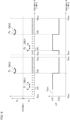
- Fig. 8 is a time chart showing a control operation for controlling the angular resolution ⁇ according to the example 1.
- a distance measurement timing occurs for every predetermined period Tr.
- the motor rotational speed is set to a first value v 1 .
- the rotational angle ⁇ is changed with a first slope.
- the scan angle ⁇ is increased with a given slope ⁇ 1 .
- the angular resolution ⁇ 1 is represented by ⁇ 1 ⁇ Tr.
- the rotational speed of the motor is set to a second value v 2 that is smaller than the first value v 1 .
- the motor rotational angle ⁇ is changed with a second slope.
- the scan angle ⁇ is increased with a relatively small slope ⁇ 2 ( ⁇ ⁇ 1 ).
- the corresponding angular resolution ⁇ 2 is represented by ⁇ 2 ⁇ Tr.
- the angular resolution ⁇ can be controlled.
- a stepping motor is employed as the motor 122.
- the processor 140 is able to control the rotational speed according to the frequency of pulses supplied to the motor 122. Specifically, this arrangement allows the rotational angle to be controlled according to the number of pulses thus supplied. With such an arrangement employing such a stepping motor, an open-loop control operation can be supported, thereby allowing the position sensor 129 to be omitted.
- the distance measurement sensor 100 is configured to change the distance measurement period Tr while maintaining the motor rotational speed at a constant value.
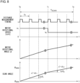
- Fig. 9 is a time chart with respect to the control operation for controlling the angular resolution ⁇ according to the example 2.
- the motor rotational speed is maintained at a constant value v 0 over the entire scanning period T SCAN . Accordingly, the scan angle ⁇ is increased with a constant slope ⁇ 0 .
- the distance measurement period Tr is set to a relatively long period, i.e., a first value Tr 1 .
- the angular resolution ⁇ 1 is represented by ⁇ 0 ⁇ Tr 1 .
- the distance measurement period Tr is set to a relatively short period, i.e., a second value Tr 2 .
- the angular resolution ⁇ 2 is represented by ⁇ 0 ⁇ Tr 2 .
- the angular resolution ⁇ can be controlled.
- An example 3 is configured as a combination of the examples 1 and 2. Specifically, both the motor rotational speed and the distance measurement period Tr are changed. This allows the angular resolution ⁇ to be adjusted.
- Fig. 10 is a block diagram showing an automobile provided with the distance measurement sensor 100.
- An automobile 300 is provided with headlamps 302L and 302R. At least one from among the headlamps 302L and 302R is provided with the distance measurement sensor 100 as a built-in component.
- Each headlamp 302 is positioned at a frontmost end of the vehicle body, which is most advantageous as a position where the distance measurement sensor 100 is to be installed for detecting an object in the vicinity.
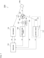
- Fig. 11 is a block diagram showing an automotive lamp 200 including the distance measurement sensor 100.
- the automotive lamp 200 forms a lamp system 310 together with an in-vehicle ECU 304.
- the automotive lamp 200 includes a light source 202, a lighting circuit 204, and an optical system 206.
- the automotive lamp 200 is provided with an object detection system 400.
- the object detection system 400 includes the above-described distance measurement sensor 100 and a processing device 410.
- the processing device 410 judges the presence or absence and the kind of an object OBJ in front of the vehicle based on point cloud data acquired by the distance measurement sensor 100.
- the processing device 410 may include an identifying device that operates based on a trained model acquired by machine learning.
- the information with respect to the object OBJ detected by the processing device 410 may be used to support the light distribution control operation of the automotive lamp 200.
- a lamp ECU 208 generates a suitable light distribution pattern based on the information with respect to the kind of the object OBJ and the position thereof thus generated by the processing device 410.
- the lighting circuit 204 and the optical system 206 operate so as to provide the light distribution pattern generated by the lamp ECU 208.
- the information with respect to the object OBJ detected by the processing device 410 may be transmitted to the in-vehicle ECU 304.
- the in-vehicle ECU may support autonomous driving based on the information thus transmitted.
- the distance measurement sensor 100 that supports a single scan line. Also, the distance measurement sensor 100 may support multiple scan lines.
- the angular resolution ⁇ is designed such that the spatial resolution ⁇ x in the scan direction is maintained to be as uniform as possible regardless of the distance d to the object.
- the present invention is not restricted to such an example.
- the spatial resolution ⁇ x may be designed to be changed according to the distance d to the object.
- the distance measurement sensor 100 is mounted on a lamp as an example application of the distance measurement sensor 100.
- the usage of the distance measurement sensor 100 is not restricted to such an example. Rather, the distance measurement sensor 100 is applicable to various kinds of usages that do not require the level of performance of high-cost commercially available LiDAR.
- the present invention relates to a distance measurement technique.
- 100 distance measurement sensor 110 light source, 120 scanning device, 122 motor, 124 rotational shaft, 126 mirror, 130 photosensor, 140 processor, 200 automotive lamp, 202 light source, 204 lighting circuit, 206 optical system, 300 automobile, 302 headlamp, 310 lamp system, 304 in-vehicle ECU, 400 object detection system, 410 processing device.
Landscapes
- Physics & Mathematics (AREA)
- Engineering & Computer Science (AREA)
- General Physics & Mathematics (AREA)
- Computer Networks & Wireless Communication (AREA)
- Radar, Positioning & Navigation (AREA)
- Remote Sensing (AREA)
- Electromagnetism (AREA)
- Optics & Photonics (AREA)
- Optical Radar Systems And Details Thereof (AREA)
- Measurement Of Optical Distance (AREA)
Claims (6)
- Abstandsmessungssensor (100), der Folgendes umfasst:eine Lichtquelle (110);eine Abtastvorrichtung (120), die einen Motor (122) und einen Spiegel (126) umfasst, der an dem Motor (122) angebracht und dazu strukturiert ist, emittiertes Licht der Lichtquelle (110) zu reflektieren, wobei die Abtastvorrichtung (120) so strukturiert ist, dass Abtastsondenlicht, das von dem Spiegel reflektiertes Licht ist, gemäß einer Drehung des Motors abgetastet werden kann;einen Fotosensor (130), der dazu strukturiert ist, während einer Abtastperiode Rücklicht (L3) zu detektieren, das das Sondenlicht ist, das von einem Punkt (P) auf einem Objekt (OBJ) reflektiert wird; undeinen Prozessor (140), der dazu strukturiert ist, basierend auf einer Ausgabe des Fotosensors (130) einen Abstand zu dem Punkt (P) auf dem Objekt (OBJ) zu detektieren,dadurch gekennzeichnet, dass eine Winkelauflösung in einer Abtastrichtung während der Abtastperiode dynamisch gemäß dem Abstand zu dem Punkt (P) auf dem Objekt (OBJ) geändert wird.
- Abstandsmessungssensor (100) nach Anspruch 1, wobei eine Drehzahl des Motors (122) gemäß dem Abstand zum Objekt (OBJ) geändert wird.
- Abstandsmessungssensor (100) nach Anspruch 1 oder 2, wobei eine Abstandsmessungsperiode gemäß dem Abstand zum Objekt (OBJ) geändert wird.
- Abstandsmessungssensor (100) nach einem der Ansprüche 1 bis 3, wobei die Winkelauflösung auf eine diskrete Weise gemäß dem Abstand zum Objekt (OBJ) geändert wird.
- Kraftfahrzeugleuchte (200), die umfasst:den Abstandsmessungssensor (100) nach einem der Ansprüche 1 bis 4;eine variable Lichtverteilungsleuchte (202,204,206); undeine Steuerung (208), die dazu strukturiert ist, die variable Lichtverteilungsleuchte (202,204,206) gemäß einer Ausgabe des Abstandsmessungssensors (100) zu steuern.
- Abstandsmessverfahren, das Folgendes umfasst:Drehen eines Motors (122), an dem ein Spiegel (126) befestigt ist;Strahlen von Licht auf den Spiegel (126), um von dem Spiegel (126) reflektiertes Licht abzutasten;Detektieren von Rücklicht (L3), das von einem Objekt (OBJ) reflektiertes Licht ist, während einer Abtastperiode mittels eines Fotosensors (130);Detektieren, durch Berechnung, eines Abstands zu einem Punkt (P) auf dem Objekt (OBJ) basierend auf einer Ausgabe des Fotosensors (130); dadurch gekennzeichnet, dass das Verfahren ferner Folgendes umfasstdynamisches Ändern einer Winkelauflösung in einer Abtastrichtung gemäß dem Abstand zum Punkt (P) auf dem Objekt (OBJ) während der Abtastperiode.
Applications Claiming Priority (2)
| Application Number | Priority Date | Filing Date | Title |
|---|---|---|---|
| JP2018225761 | 2018-11-30 | ||
| PCT/JP2019/045094 WO2020110801A1 (ja) | 2018-11-30 | 2019-11-18 | 測距センサおよび車両用灯具、測距方法 |
Publications (3)
| Publication Number | Publication Date |
|---|---|
| EP3889639A1 EP3889639A1 (de) | 2021-10-06 |
| EP3889639A4 EP3889639A4 (de) | 2022-01-05 |
| EP3889639B1 true EP3889639B1 (de) | 2025-06-25 |
Family
ID=70852873
Family Applications (1)
| Application Number | Title | Priority Date | Filing Date |
|---|---|---|---|
| EP19889042.8A Active EP3889639B1 (de) | 2018-11-30 | 2019-11-18 | Entfernungsmessungssensor, fahrzeugleuchte und entfernungsmessverfahren |
Country Status (5)
| Country | Link |
|---|---|
| US (1) | US20210311191A1 (de) |
| EP (1) | EP3889639B1 (de) |
| JP (1) | JP7339277B2 (de) |
| CN (1) | CN111257898A (de) |
| WO (1) | WO2020110801A1 (de) |
Families Citing this family (4)
| Publication number | Priority date | Publication date | Assignee | Title |
|---|---|---|---|---|
| WO2022149715A1 (ko) * | 2021-01-11 | 2022-07-14 | 삼성전자주식회사 | 청소 로봇 및 그 제어 방법 |
| CN113759342B (zh) * | 2021-08-31 | 2023-10-24 | 柳州柳工叉车有限公司 | 一种激光雷达的扫描方法、装置、计算机设备和存储介质 |
| JP7680977B2 (ja) | 2022-03-02 | 2025-05-21 | 株式会社東芝 | 画像処理装置、測距装置、及び画像処理方法 |
| JP7651603B2 (ja) * | 2023-03-27 | 2025-03-26 | 本田技研工業株式会社 | 外界認識装置 |
Citations (1)
| Publication number | Priority date | Publication date | Assignee | Title |
|---|---|---|---|---|
| US20180045826A1 (en) * | 2016-08-12 | 2018-02-15 | Koito Manufacturing Co., Ltd. | Illumination device |
Family Cites Families (11)
| Publication number | Priority date | Publication date | Assignee | Title |
|---|---|---|---|---|
| JPH10151987A (ja) * | 1996-11-25 | 1998-06-09 | Honda Access Corp | 車両の前方照明装置 |
| JP2008241273A (ja) | 2007-03-26 | 2008-10-09 | Ihi Corp | レーザレーダ装置とその制御方法 |
| JP2009098023A (ja) | 2007-10-17 | 2009-05-07 | Toyota Motor Corp | 物体検出装置及び物体検出方法 |
| DE102010061382B4 (de) * | 2010-12-21 | 2019-02-14 | Sick Ag | Optoelektronischer Sensor und Verfahren zur Erfassung und Abstandsbestimmung von Objekten |
| EP2541273B1 (de) * | 2011-06-28 | 2013-05-22 | Sick Ag | Erfassung und Abstandsbestimmung von Objekten |
| JP6135120B2 (ja) * | 2012-12-19 | 2017-05-31 | 富士通株式会社 | 距離測定装置、距離測定方法及びプログラム |
| CN204679638U (zh) * | 2015-06-24 | 2015-09-30 | 武汉万集信息技术有限公司 | 一种可变扫描分辨率的激光测距传感器 |
| US9576185B1 (en) | 2015-09-14 | 2017-02-21 | Toyota Motor Engineering & Manufacturing North America, Inc. | Classifying objects detected by 3D sensors for autonomous vehicle operation |
| US10761195B2 (en) * | 2016-04-22 | 2020-09-01 | OPSYS Tech Ltd. | Multi-wavelength LIDAR system |
| DE102016115201A1 (de) * | 2016-08-16 | 2018-02-22 | Sick Ag | Verfahren zum Betreiben eines Überwachungssensors und Überwachungssensor |
| WO2019064750A1 (ja) | 2017-09-27 | 2019-04-04 | 日本電産株式会社 | 距離測定装置、および移動体 |
-
2019
- 2019-11-18 EP EP19889042.8A patent/EP3889639B1/de active Active
- 2019-11-18 JP JP2020558379A patent/JP7339277B2/ja active Active
- 2019-11-18 WO PCT/JP2019/045094 patent/WO2020110801A1/ja not_active Ceased
- 2019-11-26 CN CN201911171443.6A patent/CN111257898A/zh active Pending
-
2021
- 2021-05-27 US US17/332,107 patent/US20210311191A1/en not_active Abandoned
Patent Citations (1)
| Publication number | Priority date | Publication date | Assignee | Title |
|---|---|---|---|---|
| US20180045826A1 (en) * | 2016-08-12 | 2018-02-15 | Koito Manufacturing Co., Ltd. | Illumination device |
Also Published As
| Publication number | Publication date |
|---|---|
| US20210311191A1 (en) | 2021-10-07 |
| CN111257898A (zh) | 2020-06-09 |
| EP3889639A1 (de) | 2021-10-06 |
| EP3889639A4 (de) | 2022-01-05 |
| JP7339277B2 (ja) | 2023-09-05 |
| JPWO2020110801A1 (ja) | 2021-10-14 |
| WO2020110801A1 (ja) | 2020-06-04 |
Similar Documents
| Publication | Publication Date | Title |
|---|---|---|
| EP3889639B1 (de) | Entfernungsmessungssensor, fahrzeugleuchte und entfernungsmessverfahren | |
| KR101997095B1 (ko) | 수평 분해능 및 영상획득 프레임이 제어되는 스캐닝 라이다 | |
| CN109444855B (zh) | 激光雷达及其扫描方法 | |
| US7650239B2 (en) | Object recognition apparatus for motor vehicle | |
| US10048381B2 (en) | Opto-electronic detection device and method for sensing the surroundings of a motor vehicle by scanning | |
| US20050219506A1 (en) | Object recognition device for vehicle | |
| CN112567266A (zh) | 用于车辆的检测系统 | |
| CN113874756B (zh) | 用于可转向激光雷达的情境感知实时功率调整 | |
| JP2003501635A (ja) | 対象検出システム | |
| US7411661B2 (en) | Laser radar for vehicle using reflector and method for controlling the same | |
| US7158075B2 (en) | Vehicle radar apparatus | |
| CN110703223B (zh) | 应用于激光雷达的调节方法和电子设备 | |
| KR20180058068A (ko) | 360도 다채널 스캐닝이 가능한 미러 회전 방식의 광학 구조 및 이를 포함하는 3d 라이다 시스템 | |
| JP2022001863A (ja) | 水平関心領域の適合 | |
| JP2004184331A (ja) | 車両用物体認識装置 | |
| JP6186863B2 (ja) | 測距装置及びプログラム | |
| US8965142B2 (en) | Method and device for classifying a light object located ahead of a vehicle | |
| EP3579014A1 (de) | Messvorrichtung | |
| US20210286081A1 (en) | Vehicular object identification system | |
| US20110199252A1 (en) | Sensor device having a variable azimuthal detection range for a motor vehicle | |
| EP3709052A1 (de) | Objektdetektor | |
| JP6736682B2 (ja) | センサ装置、センシング方法、プログラム及び記憶媒体 | |
| US20220229192A1 (en) | Optical ranging device and control method for optical ranging device | |
| EP3508873B1 (de) | Messvorrichtung, steuerungsverfahren, steuerungsverfahren und programm | |
| EP4418003A1 (de) | Entfernungsmessvorrichtung und entfernungsmesssystem |
Legal Events
| Date | Code | Title | Description |
|---|---|---|---|
| STAA | Information on the status of an ep patent application or granted ep patent |
Free format text: STATUS: THE INTERNATIONAL PUBLICATION HAS BEEN MADE |
|
| PUAI | Public reference made under article 153(3) epc to a published international application that has entered the european phase |
Free format text: ORIGINAL CODE: 0009012 |
|
| STAA | Information on the status of an ep patent application or granted ep patent |
Free format text: STATUS: REQUEST FOR EXAMINATION WAS MADE |
|
| 17P | Request for examination filed |
Effective date: 20210609 |
|
| AK | Designated contracting states |
Kind code of ref document: A1 Designated state(s): AL AT BE BG CH CY CZ DE DK EE ES FI FR GB GR HR HU IE IS IT LI LT LU LV MC MK MT NL NO PL PT RO RS SE SI SK SM TR |
|
| A4 | Supplementary search report drawn up and despatched |
Effective date: 20211207 |
|
| RIC1 | Information provided on ipc code assigned before grant |
Ipc: G02B 26/10 20060101ALI20211201BHEP Ipc: G02B 26/08 20060101ALI20211201BHEP Ipc: G01S 17/42 20060101ALI20211201BHEP Ipc: G01S 17/931 20200101ALI20211201BHEP Ipc: G01S 7/481 20060101AFI20211201BHEP |
|
| DAV | Request for validation of the european patent (deleted) | ||
| DAX | Request for extension of the european patent (deleted) | ||
| GRAP | Despatch of communication of intention to grant a patent |
Free format text: ORIGINAL CODE: EPIDOSNIGR1 |
|
| STAA | Information on the status of an ep patent application or granted ep patent |
Free format text: STATUS: GRANT OF PATENT IS INTENDED |
|
| GRAS | Grant fee paid |
Free format text: ORIGINAL CODE: EPIDOSNIGR3 |
|
| INTG | Intention to grant announced |
Effective date: 20250422 |
|
| GRAA | (expected) grant |
Free format text: ORIGINAL CODE: 0009210 |
|
| STAA | Information on the status of an ep patent application or granted ep patent |
Free format text: STATUS: THE PATENT HAS BEEN GRANTED |
|
| AK | Designated contracting states |
Kind code of ref document: B1 Designated state(s): AL AT BE BG CH CY CZ DE DK EE ES FI FR GB GR HR HU IE IS IT LI LT LU LV MC MK MT NL NO PL PT RO RS SE SI SK SM TR |
|
| REG | Reference to a national code |
Ref country code: GB Ref legal event code: FG4D |
|
| REG | Reference to a national code |
Ref country code: CH Ref legal event code: EP |
|
| REG | Reference to a national code |
Ref country code: CH Ref legal event code: EP |
|
| REG | Reference to a national code |
Ref country code: IE Ref legal event code: FG4D |
|
| REG | Reference to a national code |
Ref country code: DE Ref legal event code: R096 Ref document number: 602019071739 Country of ref document: DE |
|
| P01 | Opt-out of the competence of the unified patent court (upc) registered |
Free format text: CASE NUMBER: APP_29022/2025 Effective date: 20250618 |
|
| PG25 | Lapsed in a contracting state [announced via postgrant information from national office to epo] |
Ref country code: FI Free format text: LAPSE BECAUSE OF FAILURE TO SUBMIT A TRANSLATION OF THE DESCRIPTION OR TO PAY THE FEE WITHIN THE PRESCRIBED TIME-LIMIT Effective date: 20250625 |
|
| REG | Reference to a national code |
Ref country code: LT Ref legal event code: MG9D |
|
| PG25 | Lapsed in a contracting state [announced via postgrant information from national office to epo] |
Ref country code: NO Free format text: LAPSE BECAUSE OF FAILURE TO SUBMIT A TRANSLATION OF THE DESCRIPTION OR TO PAY THE FEE WITHIN THE PRESCRIBED TIME-LIMIT Effective date: 20250925 Ref country code: GR Free format text: LAPSE BECAUSE OF FAILURE TO SUBMIT A TRANSLATION OF THE DESCRIPTION OR TO PAY THE FEE WITHIN THE PRESCRIBED TIME-LIMIT Effective date: 20250926 |
|
| PG25 | Lapsed in a contracting state [announced via postgrant information from national office to epo] |
Ref country code: BG Free format text: LAPSE BECAUSE OF FAILURE TO SUBMIT A TRANSLATION OF THE DESCRIPTION OR TO PAY THE FEE WITHIN THE PRESCRIBED TIME-LIMIT Effective date: 20250625 |
|
| PG25 | Lapsed in a contracting state [announced via postgrant information from national office to epo] |
Ref country code: HR Free format text: LAPSE BECAUSE OF FAILURE TO SUBMIT A TRANSLATION OF THE DESCRIPTION OR TO PAY THE FEE WITHIN THE PRESCRIBED TIME-LIMIT Effective date: 20250625 |
|
| PGFP | Annual fee paid to national office [announced via postgrant information from national office to epo] |
Ref country code: FR Payment date: 20250930 Year of fee payment: 7 |
|
| PG25 | Lapsed in a contracting state [announced via postgrant information from national office to epo] |
Ref country code: RS Free format text: LAPSE BECAUSE OF FAILURE TO SUBMIT A TRANSLATION OF THE DESCRIPTION OR TO PAY THE FEE WITHIN THE PRESCRIBED TIME-LIMIT Effective date: 20250925 |
|
| PG25 | Lapsed in a contracting state [announced via postgrant information from national office to epo] |
Ref country code: LV Free format text: LAPSE BECAUSE OF FAILURE TO SUBMIT A TRANSLATION OF THE DESCRIPTION OR TO PAY THE FEE WITHIN THE PRESCRIBED TIME-LIMIT Effective date: 20250625 |
|
| REG | Reference to a national code |
Ref country code: NL Ref legal event code: MP Effective date: 20250625 |
|
| PG25 | Lapsed in a contracting state [announced via postgrant information from national office to epo] |
Ref country code: NL Free format text: LAPSE BECAUSE OF FAILURE TO SUBMIT A TRANSLATION OF THE DESCRIPTION OR TO PAY THE FEE WITHIN THE PRESCRIBED TIME-LIMIT Effective date: 20250625 |
|
| PG25 | Lapsed in a contracting state [announced via postgrant information from national office to epo] |
Ref country code: PT Free format text: LAPSE BECAUSE OF FAILURE TO SUBMIT A TRANSLATION OF THE DESCRIPTION OR TO PAY THE FEE WITHIN THE PRESCRIBED TIME-LIMIT Effective date: 20251027 |
|
| REG | Reference to a national code |
Ref country code: AT Ref legal event code: MK05 Ref document number: 1807002 Country of ref document: AT Kind code of ref document: T Effective date: 20250625 |
|
| PG25 | Lapsed in a contracting state [announced via postgrant information from national office to epo] |
Ref country code: IS Free format text: LAPSE BECAUSE OF FAILURE TO SUBMIT A TRANSLATION OF THE DESCRIPTION OR TO PAY THE FEE WITHIN THE PRESCRIBED TIME-LIMIT Effective date: 20251025 |
|
| PG25 | Lapsed in a contracting state [announced via postgrant information from national office to epo] |
Ref country code: AT Free format text: LAPSE BECAUSE OF FAILURE TO SUBMIT A TRANSLATION OF THE DESCRIPTION OR TO PAY THE FEE WITHIN THE PRESCRIBED TIME-LIMIT Effective date: 20250625 Ref country code: SM Free format text: LAPSE BECAUSE OF FAILURE TO SUBMIT A TRANSLATION OF THE DESCRIPTION OR TO PAY THE FEE WITHIN THE PRESCRIBED TIME-LIMIT Effective date: 20250625 |
|
| PG25 | Lapsed in a contracting state [announced via postgrant information from national office to epo] |
Ref country code: CZ Free format text: LAPSE BECAUSE OF FAILURE TO SUBMIT A TRANSLATION OF THE DESCRIPTION OR TO PAY THE FEE WITHIN THE PRESCRIBED TIME-LIMIT Effective date: 20250625 |
|
| PG25 | Lapsed in a contracting state [announced via postgrant information from national office to epo] |
Ref country code: PL Free format text: LAPSE BECAUSE OF FAILURE TO SUBMIT A TRANSLATION OF THE DESCRIPTION OR TO PAY THE FEE WITHIN THE PRESCRIBED TIME-LIMIT Effective date: 20250625 |
|
| PG25 | Lapsed in a contracting state [announced via postgrant information from national office to epo] |
Ref country code: EE Free format text: LAPSE BECAUSE OF FAILURE TO SUBMIT A TRANSLATION OF THE DESCRIPTION OR TO PAY THE FEE WITHIN THE PRESCRIBED TIME-LIMIT Effective date: 20250625 |
|
| PG25 | Lapsed in a contracting state [announced via postgrant information from national office to epo] |
Ref country code: SK Free format text: LAPSE BECAUSE OF FAILURE TO SUBMIT A TRANSLATION OF THE DESCRIPTION OR TO PAY THE FEE WITHIN THE PRESCRIBED TIME-LIMIT Effective date: 20250625 |
|
| PG25 | Lapsed in a contracting state [announced via postgrant information from national office to epo] |
Ref country code: ES Free format text: LAPSE BECAUSE OF FAILURE TO SUBMIT A TRANSLATION OF THE DESCRIPTION OR TO PAY THE FEE WITHIN THE PRESCRIBED TIME-LIMIT Effective date: 20250625 |