EP3888960A1 - Sunshade assembly - Google Patents
Sunshade assembly Download PDFInfo
- Publication number
- EP3888960A1 EP3888960A1 EP20166738.3A EP20166738A EP3888960A1 EP 3888960 A1 EP3888960 A1 EP 3888960A1 EP 20166738 A EP20166738 A EP 20166738A EP 3888960 A1 EP3888960 A1 EP 3888960A1
- Authority
- EP
- European Patent Office
- Prior art keywords
- guide
- slider
- sunshade
- drive
- track
- Prior art date
- Legal status (The legal status is an assumption and is not a legal conclusion. Google has not performed a legal analysis and makes no representation as to the accuracy of the status listed.)
- Granted
Links
Images


Classifications
-
- B—PERFORMING OPERATIONS; TRANSPORTING
- B60—VEHICLES IN GENERAL
- B60J—WINDOWS, WINDSCREENS, NON-FIXED ROOFS, DOORS, OR SIMILAR DEVICES FOR VEHICLES; REMOVABLE EXTERNAL PROTECTIVE COVERINGS SPECIALLY ADAPTED FOR VEHICLES
- B60J7/00—Non-fixed roofs; Roofs with movable panels, e.g. rotary sunroofs
- B60J7/0007—Non-fixed roofs; Roofs with movable panels, e.g. rotary sunroofs moveable head-liners, screens, curtains or blinds for ceilings
- B60J7/0015—Non-fixed roofs; Roofs with movable panels, e.g. rotary sunroofs moveable head-liners, screens, curtains or blinds for ceilings roller blind
-
- B—PERFORMING OPERATIONS; TRANSPORTING
- B60—VEHICLES IN GENERAL
- B60J—WINDOWS, WINDSCREENS, NON-FIXED ROOFS, DOORS, OR SIMILAR DEVICES FOR VEHICLES; REMOVABLE EXTERNAL PROTECTIVE COVERINGS SPECIALLY ADAPTED FOR VEHICLES
- B60J7/00—Non-fixed roofs; Roofs with movable panels, e.g. rotary sunroofs
- B60J7/0007—Non-fixed roofs; Roofs with movable panels, e.g. rotary sunroofs moveable head-liners, screens, curtains or blinds for ceilings
- B60J7/0023—Non-fixed roofs; Roofs with movable panels, e.g. rotary sunroofs moveable head-liners, screens, curtains or blinds for ceilings flexible and foldable
-
- B—PERFORMING OPERATIONS; TRANSPORTING
- B60—VEHICLES IN GENERAL
- B60J—WINDOWS, WINDSCREENS, NON-FIXED ROOFS, DOORS, OR SIMILAR DEVICES FOR VEHICLES; REMOVABLE EXTERNAL PROTECTIVE COVERINGS SPECIALLY ADAPTED FOR VEHICLES
- B60J1/00—Windows; Windscreens; Accessories therefor
- B60J1/20—Accessories, e.g. wind deflectors, blinds
- B60J1/2011—Blinds; curtains or screens reducing heat or light intensity
- B60J1/2013—Roller blinds
- B60J1/2066—Arrangement of blinds in vehicles
- B60J1/2069—Arrangement of blinds in vehicles of multiple blinds, e.g. more than one blind per window or per actuation system
-
- B—PERFORMING OPERATIONS; TRANSPORTING
- B60—VEHICLES IN GENERAL
- B60J—WINDOWS, WINDSCREENS, NON-FIXED ROOFS, DOORS, OR SIMILAR DEVICES FOR VEHICLES; REMOVABLE EXTERNAL PROTECTIVE COVERINGS SPECIALLY ADAPTED FOR VEHICLES
- B60J7/00—Non-fixed roofs; Roofs with movable panels, e.g. rotary sunroofs
- B60J7/02—Non-fixed roofs; Roofs with movable panels, e.g. rotary sunroofs of sliding type, e.g. comprising guide shoes
- B60J7/06—Non-fixed roofs; Roofs with movable panels, e.g. rotary sunroofs of sliding type, e.g. comprising guide shoes with non-rigid element or elements
- B60J7/067—Non-fixed roofs; Roofs with movable panels, e.g. rotary sunroofs of sliding type, e.g. comprising guide shoes with non-rigid element or elements sliding and winding up
Definitions
- the invention relates to a sunshade assembly according to the preamble of claim 1 or 13.
- a roof assembly having such drive and guide system is known from JP H10129268 A2 .
- One drive cable is operating a front and a rear mechanism which require a different travel length of operation per mechanism.
- the drive cable operates through a pin/curve in association with a locking lever which locks or unlocks the front mechanism while still moving the rear mechanism.
- the sunshade assembly according to the invention comprises the features of the characterizing portion of claim 1.
- the connecting guide itself is shaped to cause the coupling member to move, the structure can be relatively simple without various movable parts.
- the coupling member is rotatable around an axis substantially parallel to the first slider track, and in that the connecting guide is shaped to cause the rotation of the coupling member.
- the coupling member is fixed to the elongated first drive member which is able to be twisted around its longitudinal axis.
- Such twisting is for example possible with well-known push-and-pull cables as elongated drive member, and in that case the cable itself ensures a return force which may make control even more reliable in two directions.
- the connecting guide may comprise a longitudinal guide duct to guide the elongated first drive member, the guide duct being open through a control slit to allow the coupling member to extend between the first drive member and the counter member, the slit being curved along the length of the guide duct to cause the rotation of the coupling member.
- the coupling member and the counter member may include fitting protrusions/recesses locking the coupling member and counter member in longitudinal direction.
- Such protrusions and recesses may easily be brought into and out of engagement with each other.
- the connecting guide is injection moulded and made in at least two parts which together define the guide duct and the control slit for the coupling member.
- the connecting guide is made up of at least two injection moulded parts there is a great freedom in design of the control slit.
- the parts of the connecting guide may be provided with positioning and fixing members to fit and fix the two parts in the correct position.
- the connecting guide is provided with end portions fitting into end portions of the first and second guides.
- This manner of attachment may on the one hand ensure a smooth transition for the drive member and on the other hand ensures correct attachment of the connecting guide with respect to the first and second guides.
- the sunshades are arranged to move in opposite directions, and thus the first drive member and the second drive member are arranged to move with equal speed in opposite directions.
- first and second drive members may be separate elements arranged parallel to each other and moving in opposite directions.
- the first and second drive members are preferably arranged in series and may form two portions of a single element.
- the second end of the first guide is provided with a drive member guide into which the coupling member of the first drive member arrives when the coupling member must be uncoupled from the counter member and which is shaped to cause the movement of the coupling member when the first and second drive members move further to open or close the second sunshade member.
- Sunshades are preferably rollo sunshades but may also comprises sliding sunshade panels or other moving sunshades.
- the invention also includes a roof assembly for a vehicle having a roof opening in its fixed roof, comprising at least one closure member for closing and at least partly opening the roof opening and further comprising the sunshade assembly as described above.
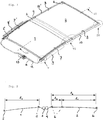
- the sunshade assembly as shown in Fig. 1 is intended for use in a roof assembly provided in one or more roof openings of a vehicle roof.
- the roof assembly may comprise a moveable panel and a fixed panel.
- the moveable panel is also referred to as a closure member, since the moveable panel is moveable over a first roof opening such to enable to open and to close a first roof opening.
- the moveable panel can be moved to a closed position, which is a position wherein the moveable panel is arranged over/within and closes the first roof opening and thus usually is arranged in a plane of the vehicle roof. Further, the moveable panel may for example be moved to a tilted position, which is a position wherein a rear end of the moveable panel is raised as compared to the closed position, while a front end of the moveable panel is still substantially in the closed position. Further, the moveable panel may be moved to an open position, which is a position wherein the moveable panel is slid open (mostly in rearward direction) and the first roof opening is partly or completely exposed. Other movements are conceivable.
- the vehicle for which the roof assembly is intended is a passenger car.
- the present invention is however not limited to passenger cars. Any other kind of vehicles, such as trucks, mobile homes or caravans that may be provided with a roof assembly and sunshade assembly are contemplated as well.
- the roof assembly includes a second roof opening which may be closed by a fixed panel such that light may enter a vehicle interior space through the fixed panel, presuming that the fixed panel is a glass panel or a similarly (semi)transparent panel, for example made of a plastic material or any other suitable material. It is noted that the second roof opening may be integral with the first roof opening.
- a roof assembly as described above may for example be like that as disclosed in US 2019/0176603 A1 , the contents of which are incorporated herein by reference thereto.
- Figs. 1 and 2 show a first embodiment of the sunshade assembly including a first or front rollo sunshade 1 to block light coming through the first roof opening and a second rollo sunshade 2 to block light coming through the second roof opening.
- a frame of the roof assembly forms a first passage opening below the first roof opening and a second passage opening below the second roof opening, which first and second passage opening are selectively opened and closed by the first and second sunshades 1, 2.
- the sunshades 1, 2 are normally made from cloth material and have an end edge attached to a winding roller 3, 4, respectively, an opposite end edge attached to an operating beam 5, 6, respectively, and opposite side edges 7, 7' and 8, 8'.
- winding rollers 3, 4 are arranged back to back so that the rollo sunshades move in opposite direction when they make a winding (opening) or unwinding (closing) movement.
- Other arrangements are conceivable.
- Fig. 1 further illustrates a drive assembly for the sunshades having a first guide 9, 9', a second guide 10, 10', a first drive cable 11 and a second drive cable 12, in this embodiment forming the elongated first and second drive members 11, 12.
- the first and second guides 9, 9' and 10, 10' are arranged to guide the respective side edges 7, 7' and 8, 8' respectively on opposite side edges of sunshades 1, 2 in a well-known manner, for example as is shown in Fig. 8 .
- the guides 9, 9', 10, 10' are generally coupled to a frame or other stationary part (not shown) below opposite side edges of the roof opening(s).
- the first and the second drive cables 11, 12 are provided to move opposite ends of operating beams 5, 6, respectively, and are driven by a drive motor 13.
- First guides 9, 9' will normally also be used for guiding an operating mechanism for the movable panel. This is not shown and does not form part of the present invention.
- the drive cables 11, 12 couple the drive motor 13 to the operating beams 5, 6.
- One end of drive cable 11 can be coupled to operating beam 5 of sunshade 1 in front guide 9, the other end - which moves in opposite direction on the other side of sunshades 1, 2 - is coupled to operating beam 6 of sunshade 2 in second guide 10'.
- One end of drive cable 12 is coupled to operating beam 6 of sunshade 2 in rear guide 10, while the opposite end - which moves in opposite direction on the other side of sunshades 1, 2 - can be coupled to operating beam 5 of front sunshade 1 in front guide 9'.
- the drive cables 11, 12 are normally push-and-pull cables well known in the art and are therefore not further elucidated herein.
- Fig. 2 shows that operating beam 5 of sunshade 1 is able to travel a length l 1 and operating beam 6 has a maximum travel length of l 2 which is a length l 3 longer than length l 1 .
- the invention provides a solution to interrupt driving one of the sunshades in a simple and effective manner.
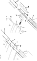
- Fig. 3a - 3c show one side edge 7, 8 of the sunshades 1, 2 and their guide and drive means. The same parts are generally present at the other side edge, albeit in mirror image, only cables 11, 12 are switched as explained above.
- Fig. 3a shows both sunshades 1, 2 in their closed (unwound) position (a part of the sunshades 1, 2 is cut away).
- Fig. 3b the front sunshade 1 has arrived in its fully open (wound) position, while rear sunshade 2 is still a length l 3 away from its open position. Cable 11 is then uncoupled from operating beam 5 of front sunshade 1, while rear sunshade 2 is continuously coupled to cable 12 and is thus driven further to the position of Fig. 3c in which both sunshades 1, 2 are open.
- Fig. 4a, 4b show the fixed coupling between cable 12 and operating beam 6 of sunshade 2.
- a coupling member 14 is clipped to cable 12, such that it is locked against sliding with respect to cable 12, but able to rotate around the longitudinal axes of cable 12 if necessary.
- Coupling member 14 is fitted into a slider 16 of operating beam 6 such that no movement between them is possible.
- Fig. 3a - 3c show that slider 16 of operating beam 6 is guided by a slider track 10a of second guide 10 between a first and second track end.
- Fig. 5a, 5b show the detachable coupling between cable 11 and operating beam 5 of sunshade 1.
- a slider 15 at the end of operating beam 5 into which a counter member 17 can be fixedly fitted. Slider 15 is guided by slider track 9a between a first and second track end (see Figs. 3a - 3c ).
- Fixed to cable 11 is a coupling member 18, for example by moulding it on the end portion of cable 11, although it would also be possible that coupling member 18 is connected to cable 11 such that it is rotatable around the longitudinal axis of cable 11.
- Coupling member 18 is provided with a lateral protrusion 19 on its end away from cable 11. Next to protrusion 19 is a lateral recess 20 and then a lateral bulge 21.
- Counter member 17 comprises a nose 22 that fits in recess 20 between protrusion 19 and bulge 21. If coupling member 18 is within guide 9, it is prevented from rotating around the axis of cable 11 and in that position nose 22 is locked in recess 20 between protrusion 19 and bulge 21 on coupling member 18.
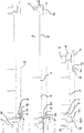
- Figs. 6a and 6b show a drive member guide or connecting guide 23 between first or front guide 9 and second or rear guide 10. It comprises in this case two parts 23a, 23b fitted together (further explained later on), together defining a first guide duct 24 for guiding the end of first cable 11 coming out of first guide 9, and a second guide duct 25 for guiding second cable 12 from first guide 9 to second guide 10. It might be supported by a bearing console 26 for the winding rollers 3, 4.
- Fig. 6b partly shows that first guide duct 24 is open on the upper side through a control slit 27.
- Figs. 7a - 7c show through a dash line 27 the curve of this control slit.
- Coupling member 18 exits through this control slit 27 to connect cable 11 (not shown) and counter member 17 of operating beam 5 of first rollo 1.
- Control slit 27 comprises a side step 27a at the position where coupling member 18 must be uncoupled/coupled from/to counter member 17.
- This side step 27a causes upper part of coupling member 18 to move in lateral direction, and because coupling member 18 is attached to cable 11, coupling member 18 will rotate around the longitudinal axis of cable 11. Due to this rotation coupling member 18 will move away/to counter member 17 such that nose 22 of counter member 17 will move out of/into recess 20 of coupling member and thereby effectively uncouple/couple cable 11 from operating beam 5 of sunshade 1.
- Fig. 7a shows that nose 22 is in engagement with recess 20 between protrusion 19 and bulge 21.
- coupling member 18 is rotated away from counter member 17 due to step 27a in control slit 27 and thus nose 22 is moved away from recess 20 to such extent that bulge 21 can pass nose 22 so that cable 11 is able to move on without taking operating beam 5 along.
- cable 12 will move operating beam 6 of second sunshade 2 to the fully open position.
- Figs. 8a - 8c show the rotation of coupling member 18 in more detail and correspond with Fig. 7a - 7c regarding the position of coupling member 18.
- coupling member 18 is within first guide 9 in which coupling member 18 is locked against rotation.
- coupling member 18 has arrived in connecting guide 23 and one wall of control slit 27 has already made way for a rotation.
- the opposite wall of control slit 27 forces coupling member 18 to rotate in order to allow nose 22 of counter member 17 to leave recess 20 and allow bulge 21 to pass and thus to disengage from coupling member 18.
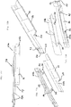
- Fig. 9 shows how one end of first guide duct 24 and the opposite ends of second guide duct 25 are inserted into first and second guides 9, 10. End parts 28' of cable channels 28 in first guide 9 and end part 29' of cable channel 29 in second guide 10 are widened to receive the ends of guide ducts 24, 25 and offer a substantially smooth guiding of cables 11, 12 (not shown here) at the transition between guides 9, 23, 10.
- guides 9, 10 are substantially aligned, but have a slight curvature to be adapted to the curvature of the fixed roof of the vehicle. Such curvature may also be present in connecting guide 23.
- Fig. 10 clearly show parts 23a, 23b of connecting guide 23 and how they are connected.
- Figs. 10a, 10b show connecting guide 23 in assembled condition, while Figs. 10c and 10d are exploded views with parts 23a and 23b separated.
- the parts 23a, 23b in this embodiment are made from plastic by injection moulding. They each have a platform 30, 31, such that platform 31 of part 23b fits onto platform 30 of part 23a.
- Platform 30 comprises two keyhole-shaped openings 32, and on the lower side of platform 31 there are formed two equally spaced mushroom-shaped knobs 33, such that the head of knobs 33 can be inserted through the larger part of openings 32 and parts 23a and 23b can then be shifted towards each other such that the second guide duct 25 is closed and then the stems of knobs 33 are within the smaller part of openings 32 and the heads of knobs 33 lock parts 23a and 23b against vertical movement.
- Small pins 34 may be provided on part 23a to securely fit into openings (not shown) in part 23b to further fix parts 23a and 23b together.
- Parts 23a and 23b may have further means in order to further fix connecting guide 23 to first and second guides 9, 10, for example springy protrusions fitting in holes in the guides.
- Figs. 11 and 12 show in a very schematic way two further embodiments of the sunshade assembly. An important difference is that in these embodiments the sunshades move in the same direction, not in opposite directions. This means that on one side edge of the sunshades 1, 2 both operating beams are driven by the same cable, on the edge as shown by cable 11.
- front sunshade 1 has a shorter unwinding length, like in Figs. 1 - 10 .
- Coupling member 18 for sunshade 1 is now attached at a distance from the end of cable 11 in order to be coupled and uncoupled from counter member 17 on operating beam 5 of sunshade 1. Uncoupling now takes place when sunshade 1 is fully closed (unwound), and sunshade 2 should be further unwound.
- Control of coupling member 18 can take place in the same way as in the former embodiment, i.e. by means of a connecting guide having a control slit.
- this connecting guide now only needs one guide duct, only for cable 11 which extends through the connecting guide from first guide 9 to second guide 10.
- the slider for the operating beam 5 should be self-braking to remain in position when cable 11 is uncoupled, or some other brake or lock should be provided to hold sunshade 1 in position.
- Fig. 12 differs in that the longer second sunshade 2 is now arranged as front sunshade.
- fixed coupling member 14 is now attached a distance from the end of cable 11 and coupling member 18 is attached to end of cable 11.
- Control of coupling member 18 must take place at the rear end of first guide 9 where a drive member guide 35 with control slit is attached to first guide 9.
- drive member guide 35 is positioned at the end of first guide 9 like connecting guide 23.
- a connecting guide might not be necessary in this embodiment and guides 9 and 10 could be integrated into one guide.
- the invention provides a simple yet effective assembly for operating two different sunshade members with a single electric motor.
- One sunshade member may be further operated while the other remains in an end position due to a simple yet reliable coupling member.
- the terms and phrases used herein are not intended to be limiting, but rather to provide an understandable description of the invention.
- the terms "a” or “an”, as used herein, are defined as one or more than one.
- the term plurality, as used herein, is defined as two or more than two.
- the term another, as used herein, is defined as at least a second or more.
- the terms including and/or having, as used herein, are defined as comprising (i.e. open language).
- the term coupled, as used herein, is defined as connected, although not necessarily directly.
Landscapes
- Engineering & Computer Science (AREA)
- Mechanical Engineering (AREA)
- Operating, Guiding And Securing Of Roll- Type Closing Members (AREA)
Abstract
Description
- The invention relates to a sunshade assembly according to the preamble of
claim - A roof assembly having such drive and guide system is known from
JP H10129268 A2 - It is an object of the present invention to provide a sunshade assembly having a coupling member which is easier to couple and uncouple.
- For this and other objects, the sunshade assembly according to the invention comprises the features of the characterizing portion of
claim 1. - Because the connecting guide itself is shaped to cause the coupling member to move, the structure can be relatively simple without various movable parts.
- Preferably the coupling member is rotatable around an axis substantially parallel to the first slider track, and in that the connecting guide is shaped to cause the rotation of the coupling member.
- Such rotation is relatively easy to accomplish in a reliable manner.
- In one embodiment, the coupling member is fixed to the elongated first drive member which is able to be twisted around its longitudinal axis.
- Such twisting is for example possible with well-known push-and-pull cables as elongated drive member, and in that case the cable itself ensures a return force which may make control even more reliable in two directions.
- The connecting guide may comprise a longitudinal guide duct to guide the elongated first drive member, the guide duct being open through a control slit to allow the coupling member to extend between the first drive member and the counter member, the slit being curved along the length of the guide duct to cause the rotation of the coupling member.
- This causes an easy control of the rotation of the coupling member without the need of any moving element.
- The coupling member and the counter member may include fitting protrusions/recesses locking the coupling member and counter member in longitudinal direction.
- Such protrusions and recesses may easily be brought into and out of engagement with each other.
- In an embodiment, the connecting guide is injection moulded and made in at least two parts which together define the guide duct and the control slit for the coupling member.
- If the connecting guide is made up of at least two injection moulded parts there is a great freedom in design of the control slit.
- The parts of the connecting guide may be provided with positioning and fixing members to fit and fix the two parts in the correct position.
- Preferably, the connecting guide is provided with end portions fitting into end portions of the first and second guides.
- This manner of attachment may on the one hand ensure a smooth transition for the drive member and on the other hand ensures correct attachment of the connecting guide with respect to the first and second guides.
- In one embodiment, the sunshades are arranged to move in opposite directions, and thus the first drive member and the second drive member are arranged to move with equal speed in opposite directions.
- In this embodiment, the first and second drive members may be separate elements arranged parallel to each other and moving in opposite directions.
- When the sunshades are arranged to move in equal directions, and thus the first drive member and the second drive member are arranged to move with equal speed in the same direction, the first and second drive members are preferably arranged in series and may form two portions of a single element.
- In another aspect of the invention, the second end of the first guide is provided with a drive member guide into which the coupling member of the first drive member arrives when the coupling member must be uncoupled from the counter member and which is shaped to cause the movement of the coupling member when the first and second drive members move further to open or close the second sunshade member.
- This enables all kinds of different arrangements of the sunshades. Sunshades are preferably rollo sunshades but may also comprises sliding sunshade panels or other moving sunshades.
- The invention also includes a roof assembly for a vehicle having a roof opening in its fixed roof, comprising at least one closure member for closing and at least partly opening the roof opening and further comprising the sunshade assembly as described above.
- Further scope of applicability of the present invention will become apparent from the detailed description given hereinafter. However, it should be understood that the detailed description and specific examples, while indicating embodiments of the invention, are given by way of illustration only, since various changes and modifications within the scope of the invention will become apparent to those skilled in the art from this detailed description with reference to the appended schematic drawings, in which:
-
Fig. 1 is a perspective view of a sunshade assembly according to the invention. -
Fig. 2 is a very schematic sectional view of the rollo configuration ofFig. 1 according to the line II-II therein. -
Figs. 3a - 3c are plan views of the drive system of the rolly assembly ofFig. 1 in 3 different positions. -
Fig. 4a and 4b are a perspective view and an exploded view, respectively, of detail IV inFig. 1 . -
Fig. 5a and 5b are views corresponding to that ofFig. 4a and 4b , but showing detail V inFig. 1 . -
Fig. 6a and 6b are views corresponding to that ofFigs. 4a and 4b , but showing detail VI inFig. 1 . -
Figs. 7a - 7c are views substantially similar to that ofFigs. 3a - 3c , showing a central part of the drive system without guide rail and on a larger scale. -
Figs. 8a - 8c are sectional views according to the lines VIIIA - VIIIa, VIIIb - VIIIb and VIIIc - VIIIc inFigs. 3a ,7a and 7b , respectively, on a larger scale. -
Fig. 9 is a sectional view according to the line IX - IX inFig. 3a on a larger scale. -
Figs. 1a 10d are a plan view, a perspective view and exploded views from above and below showing a connecting guide between the first and second guides of the sunshade assembly. -
Figs. 11 and 12 are very schematic plan views of alternative drive systems for the sunshade assembly according to the invention. - The present invention will now be described with reference to the accompanying drawings, wherein the same reference numerals have been used to identify the same or similar elements throughout the several views.
- The sunshade assembly as shown in
Fig. 1 is intended for use in a roof assembly provided in one or more roof openings of a vehicle roof. The roof assembly may comprise a moveable panel and a fixed panel. The moveable panel is also referred to as a closure member, since the moveable panel is moveable over a first roof opening such to enable to open and to close a first roof opening. - The moveable panel can be moved to a closed position, which is a position wherein the moveable panel is arranged over/within and closes the first roof opening and thus usually is arranged in a plane of the vehicle roof. Further, the moveable panel may for example be moved to a tilted position, which is a position wherein a rear end of the moveable panel is raised as compared to the closed position, while a front end of the moveable panel is still substantially in the closed position. Further, the moveable panel may be moved to an open position, which is a position wherein the moveable panel is slid open (mostly in rearward direction) and the first roof opening is partly or completely exposed. Other movements are conceivable.
- It is noted that the vehicle for which the roof assembly is intended is a passenger car. The present invention is however not limited to passenger cars. Any other kind of vehicles, such as trucks, mobile homes or caravans that may be provided with a roof assembly and sunshade assembly are contemplated as well.
- The roof assembly includes a second roof opening which may be closed by a fixed panel such that light may enter a vehicle interior space through the fixed panel, presuming that the fixed panel is a glass panel or a similarly (semi)transparent panel, for example made of a plastic material or any other suitable material. It is noted that the second roof opening may be integral with the first roof opening. A roof assembly as described above may for example be like that as disclosed in
US 2019/0176603 A1 , the contents of which are incorporated herein by reference thereto. -
Figs. 1 and 2 show a first embodiment of the sunshade assembly including a first orfront rollo sunshade 1 to block light coming through the first roof opening and asecond rollo sunshade 2 to block light coming through the second roof opening. Generally a frame of the roof assembly forms a first passage opening below the first roof opening and a second passage opening below the second roof opening, which first and second passage opening are selectively opened and closed by the first andsecond sunshades - The
sunshades roller operating beam embodiment winding rollers -
Fig. 1 further illustrates a drive assembly for the sunshades having afirst guide 9, 9', asecond guide 10, 10', afirst drive cable 11 and asecond drive cable 12, in this embodiment forming the elongated first andsecond drive members second guides respective side edges sunshades Fig. 8 . Theguides second drive cables operating beams drive motor 13. First guides 9, 9' will normally also be used for guiding an operating mechanism for the movable panel. This is not shown and does not form part of the present invention. - As mentioned, the
drive cables drive motor 13 to theoperating beams drive cable 11 can be coupled tooperating beam 5 ofsunshade 1 infront guide 9, the other end - which moves in opposite direction on the other side ofsunshades 1, 2 - is coupled tooperating beam 6 ofsunshade 2 in second guide 10'. One end ofdrive cable 12 is coupled tooperating beam 6 ofsunshade 2 inrear guide 10, while the opposite end - which moves in opposite direction on the other side ofsunshades 1, 2 - can be coupled tooperating beam 5 offront sunshade 1 in front guide 9'. Thedrive cables -
Fig. 2 shows thatoperating beam 5 ofsunshade 1 is able to travel a length l1 andoperating beam 6 has a maximum travel length of l2 which is a length l3 longer than length l1. This means that if bothsunshades sunshades sunshade 2 is moved further through a length l3. The invention provides a solution to interrupt driving one of the sunshades in a simple and effective manner. -
Fig. 3a - 3c show oneside edge sunshades cables Fig. 3a shows bothsunshades sunshades Fig. 3b , thefront sunshade 1 has arrived in its fully open (wound) position, whilerear sunshade 2 is still a length l3 away from its open position.Cable 11 is then uncoupled from operatingbeam 5 offront sunshade 1, whilerear sunshade 2 is continuously coupled tocable 12 and is thus driven further to the position ofFig. 3c in which bothsunshades -
Fig. 4a, 4b show the fixed coupling betweencable 12 andoperating beam 6 ofsunshade 2. As is shown, acoupling member 14 is clipped tocable 12, such that it is locked against sliding with respect tocable 12, but able to rotate around the longitudinal axes ofcable 12 if necessary. Couplingmember 14 is fitted into aslider 16 ofoperating beam 6 such that no movement between them is possible.Fig. 3a - 3c show thatslider 16 ofoperating beam 6 is guided by a slider track 10a ofsecond guide 10 between a first and second track end. -
Fig. 5a, 5b show the detachable coupling betweencable 11 andoperating beam 5 ofsunshade 1. There is aslider 15 at the end ofoperating beam 5 into which acounter member 17 can be fixedly fitted.Slider 15 is guided by slider track 9a between a first and second track end (seeFigs. 3a - 3c ). Fixed tocable 11 is acoupling member 18, for example by moulding it on the end portion ofcable 11, although it would also be possible that couplingmember 18 is connected tocable 11 such that it is rotatable around the longitudinal axis ofcable 11. Couplingmember 18 is provided with alateral protrusion 19 on its end away fromcable 11. Next toprotrusion 19 is alateral recess 20 and then alateral bulge 21.Counter member 17 comprises anose 22 that fits inrecess 20 betweenprotrusion 19 andbulge 21. If couplingmember 18 is withinguide 9, it is prevented from rotating around the axis ofcable 11 and in thatposition nose 22 is locked inrecess 20 betweenprotrusion 19 andbulge 21 oncoupling member 18. -
Figs. 6a and 6b show a drive member guide or connectingguide 23 between first orfront guide 9 and second orrear guide 10. It comprises in this case twoparts first guide duct 24 for guiding the end offirst cable 11 coming out offirst guide 9, and asecond guide duct 25 for guidingsecond cable 12 fromfirst guide 9 tosecond guide 10. It might be supported by a bearingconsole 26 for the windingrollers -
Fig. 6b partly shows thatfirst guide duct 24 is open on the upper side through a control slit 27. -
Figs. 7a - 7c show through adash line 27 the curve of this control slit. Couplingmember 18 exits through this control slit 27 to connect cable 11 (not shown) andcounter member 17 ofoperating beam 5 offirst rollo 1. Control slit 27 comprises aside step 27a at the position where couplingmember 18 must be uncoupled/coupled from/to countermember 17. Thisside step 27a causes upper part ofcoupling member 18 to move in lateral direction, and because couplingmember 18 is attached tocable 11,coupling member 18 will rotate around the longitudinal axis ofcable 11. Due to thisrotation coupling member 18 will move away/to countermember 17 such thatnose 22 ofcounter member 17 will move out of/intorecess 20 of coupling member and thereby effectively uncouple/couple cable 11 fromoperating beam 5 ofsunshade 1. -
Fig. 7a shows thatnose 22 is in engagement withrecess 20 betweenprotrusion 19 andbulge 21. InFig. 7b ,coupling member 18 is rotated away fromcounter member 17 due tostep 27a in control slit 27 and thusnose 22 is moved away fromrecess 20 to such extent thatbulge 21 can passnose 22 so thatcable 11 is able to move on without takingoperating beam 5 along. In the meantime,cable 12 will moveoperating beam 6 ofsecond sunshade 2 to the fully open position. -
Figs. 8a - 8c show the rotation of couplingmember 18 in more detail and correspond withFig. 7a - 7c regarding the position of couplingmember 18. InFig. 8a ,coupling member 18 is withinfirst guide 9 in whichcoupling member 18 is locked against rotation. InFig. 8b ,coupling member 18 has arrived in connectingguide 23 and one wall of control slit 27 has already made way for a rotation. InFig. 8c , the opposite wall of control slit 27forces coupling member 18 to rotate in order to allownose 22 ofcounter member 17 to leaverecess 20 and allowbulge 21 to pass and thus to disengage from couplingmember 18. -
Fig. 9 shows how one end offirst guide duct 24 and the opposite ends ofsecond guide duct 25 are inserted into first andsecond guides cable channels 28 infirst guide 9 and end part 29' ofcable channel 29 insecond guide 10 are widened to receive the ends ofguide ducts cables 11, 12 (not shown here) at the transition betweenguides guide 23. -
Fig. 10 clearly showparts guide 23 and how they are connected.Figs. 10a, 10b show connecting guide 23 in assembled condition, whileFigs. 10c and 10d are exploded views withparts parts platform platform 31 ofpart 23b fits ontoplatform 30 ofpart 23a.Platform 30 comprises two keyhole-shapedopenings 32, and on the lower side ofplatform 31 there are formed two equally spaced mushroom-shapedknobs 33, such that the head ofknobs 33 can be inserted through the larger part ofopenings 32 andparts second guide duct 25 is closed and then the stems ofknobs 33 are within the smaller part ofopenings 32 and the heads ofknobs 33lock parts part 23a to securely fit into openings (not shown) inpart 23b to further fixparts Parts guide 23 to first andsecond guides -
Figs. 11 and 12 show in a very schematic way two further embodiments of the sunshade assembly. An important difference is that in these embodiments the sunshades move in the same direction, not in opposite directions. This means that on one side edge of thesunshades cable 11. - In the embodiment of
Fig. 11 ,front sunshade 1 has a shorter unwinding length, like inFigs. 1 - 10 . This means that the end ofcable 11 is permanently coupled tooperating beam 6 ofsunshade 2. Couplingmember 18 forsunshade 1 is now attached at a distance from the end ofcable 11 in order to be coupled and uncoupled fromcounter member 17 onoperating beam 5 ofsunshade 1. Uncoupling now takes place whensunshade 1 is fully closed (unwound), andsunshade 2 should be further unwound. Control ofcoupling member 18 can take place in the same way as in the former embodiment, i.e. by means of a connecting guide having a control slit. However, this connecting guide now only needs one guide duct, only forcable 11 which extends through the connecting guide fromfirst guide 9 tosecond guide 10. The slider for theoperating beam 5 should be self-braking to remain in position whencable 11 is uncoupled, or some other brake or lock should be provided to holdsunshade 1 in position. - The embodiment of
Fig. 12 differs in that the longersecond sunshade 2 is now arranged as front sunshade. Thus fixedcoupling member 14 is now attached a distance from the end ofcable 11 andcoupling member 18 is attached to end ofcable 11. Control ofcoupling member 18 must take place at the rear end offirst guide 9 where a drive member guide 35 with control slit is attached tofirst guide 9. Thus, drive member guide 35 is positioned at the end offirst guide 9 like connectingguide 23. A connecting guide might not be necessary in this embodiment and guides 9 and 10 could be integrated into one guide. - From the foregoing it has become clear that the invention provides a simple yet effective assembly for operating two different sunshade members with a single electric motor. One sunshade member may be further operated while the other remains in an end position due to a simple yet reliable coupling member.
- Detailed embodiments of the present invention are disclosed herein; however, it is to be understood that the disclosed embodiments are merely exemplary of the invention, which can be embodied in various forms. Therefore, specific structural and functional details disclosed herein are not to be interpreted as limiting, but merely as a basis for the claims and as a representative basis for teaching one skilled in the art to variously employ the present invention in expectedly any appropriately detailed structure. In particular, features presented and described in separate dependent claims may be applied in combination and any advantageous combination of such claims are herewith disclosed.
- Further, the terms and phrases used herein are not intended to be limiting, but rather to provide an understandable description of the invention. The terms "a" or "an", as used herein, are defined as one or more than one. The term plurality, as used herein, is defined as two or more than two. The term another, as used herein, is defined as at least a second or more. The terms including and/or having, as used herein, are defined as comprising (i.e. open language). The term coupled, as used herein, is defined as connected, although not necessarily directly.
- The invention being thus described it is apparent that the same may be varied in many ways. Such variations are not to be regarded as a departure from the spirit and scope of the invention, and all such modifications as would be apparent to one skilled in the art are intended to be included within the scope of the following claims.
Claims (15)
- Sunshade assembly for a vehicle having at least one roof opening in its fixed roof, comprising at least a first (1) and second (2) moveably arranged sunshade positioned one behind the other and each provided for covering a passage opening below the at least one roof opening and a drive assembly for moving the sunshades (1, 2), the drive assembly comprising:• a first guide (9)_defining a first slider track (9a) extending between a first track end and a second track end;• an elongated first drive member (11) operatively guided by a guide channel (28) of the first guide (9),• a first slider (15) arranged to be coupled to the first drive member (11) through a first coupling (17, 18) and connected to the first sunshade (1);• a second guide (10) defining a second slider track (10a) extending between a first track end and a second track end, the first guide (9) being substantially aligned with the second guide (10),• an elongated second drive member (12) operatively guided by a guide channel (29) in the second guide (10),• a second slider (16) attached to the second drive member (12) and connected to the second sunshade (2),• a drive motor (13) operatively coupled to the first drive member (11) for moving the first slider (15) along the first slider track (9a) between the first track end and the second track end and guided by the guide channel (28) of the first guide (9) in order to move the first sunshade (1), and operatively coupled to the second drive member (12) for moving the second slider (16) along the second slider track (10a) between the first track end and the second track end of the second slider track and guided by the guide channel (29) of the second guide (10) in order to move the second sunshade (2),• a connecting guide (23) connecting the first and second guides (9, 10) to guide at least one of the first and elongated second drive members (11, 12) between the first and second guides (9, 10),wherein the second slider track (10a) is longer than the first slider track (9a), and wherein the first coupling (17, 18) between the elongated first drive member (11) and the first slider (15) can be uncoupled to drive the second slider (16) while not driving the first slider, and wherein the first coupling (17, 18) includes a coupling member (18) connected to the first drive member (11) to couple and uncouple the coupling member (18) from a counter member (17) on the first slider (15) by a movement of the coupling member (18), characterized in that the connecting guide (23) is shaped to cause the movement of the coupling member (18) when the drive members (11, 12) move in order to open or close the first and second sunshades (1, 2).
- The sunshade assembly of claim 1, wherein the coupling member (18) is rotatable around an axis substantially parallel to the first slider track (9), and in that the connecting guide (23) is shaped to cause the rotation of the coupling member (18).
- The sunshade assembly of claim 2, wherein the coupling member (18) is fixed to the elongated first drive member (11) which is able to be twisted around its longitudinal axis.
- The sunshade assembly of claim 2 or 3, wherein the connecting guide (23) comprises a longitudinal first guide duct (24) to guide the first drive member (11), the first guide duct (24) being open through a control slit (27) to allow the coupling member (18) to extend between the first drive member (11) and the counter member (17), the control slit (27) being curved along the length of the first guide duct (24) to cause the rotation of the coupling member (18).
- The sunshade assembly of any of the preceding claims, wherein the coupling member (18) and the counter member (17) include fitting protrusions (19, 21, 22) locking the coupling member (18) and counter member (17) in longitudinal direction.
- The sunshade assembly of claim 4, wherein the connecting guide (23) is injection moulded and made in at least two parts (23a, 23b) which together define the first guide duct (24) and the control slit (27) for the coupling member (18).
- The sunshade assembly of claim 6, wherein the parts (23a, 23b)of the connecting guide (23) are provided with positioning and fixing members (32, 33, 34) to fit and fix the two parts in the correct position.
- The sunshade assembly of any of the preceding claims, wherein the connecting guide (23) is provided with end portions fitting into end portions (28a, 29a) of the first and second guides (9, 10).
- The sunshade assembly of any of the preceding claims, wherein the sunshades (1, 2) are arranged to move in opposite directions, and thus the first drive member (11) and the second drive member (12) are arranged to move with equal speed in opposite directions.
- The sunshade assembly of claim 9, wherein the first and second drive members (11, 12) are separate elements arranged parallel to each other and moving in opposite directions.
- The sunshade assembly of any of claims 1 - 8, wherein the sunshades (1, 2) are arranged to move in equal directions, and thus the first drive member (11) and the second drive member (12) are arranged to move with equal speed in the same direction.
- The sunshade assembly of claim 11, wherein the first and second drive members (11, 12) are arranged in series and may form two portions of a single element.
- Sunshade assembly for a vehicle having at least one roof opening in its fixed roof, comprising at least a first (1) and second (2) moveably arranged sunshade positioned one behind the other and each provided for covering a passage opening below the at least one roof opening and a drive assembly for moving the sunshades (1, 2), the drive assembly comprising:• a first guide (9)_defining a first slider track (9a) extending between a first track end and a second track end;• an elongated first drive member (11) operatively guided by a guide channel (28) of the first guide (9),• a first slider (15) arranged to be coupled to the first drive member (11) through a first coupling (17, 18) and connected to the first sunshade (1);• a second guide (10) defining a second slider track (10a) extending between a first track end and a second track end, the first guide (9) being substantially aligned with the second guide (10),• an elongated second drive member (12) operatively guided by a guide channel (29) in the second guide (10),• a second slider (16) attached to the second drive member (12) and connected to the second sunshade (2),• a drive motor (13) operatively coupled to the first drive member (11) for moving the first slider (15) along the first slider track (9a) between the first track end and the second track end and guided by the guide channel (28) of the first guide (9) in order to move the first sunshade (1), and operatively coupled to the second drive member (12) for moving the second slider (16) along the second slider track (10a) between the first track end and the second track end of the second slider track and guided by the guide channel (29) of the second guide (10) in order to move the second sunshade (2),wherein the second slider track (10a) is longer than the first slider track (9a), and wherein the first coupling (17, 18) between the elongated first drive member (11) and the first slider (15) can be uncoupled to drive the second slider (16) while not driving the first slider, and wherein the first coupling (17, 18) includes a coupling member (18) connected to the first drive member (11) to couple and uncouple the coupling member (18) from a counter member (17) on the first slider (15) by a movement of the coupling member (18), characterized in that the second end of the first guide (9) is provided with a drive member guide (23, 35) into which the coupling member (18) of the first drive member (11) arrives when the coupling member (18) must be uncoupled from the counter member (17) and which is shaped to cause the movement of the coupling member (18) when the first and second drive members (11, 12) move further to open or close the second sunshade (2).
- The sunshade assembly of claim 13, wherein the drive member guide (23, 35) is made by injection moulding.
- A roof assembly for a vehicle having a roof opening in its fixed roof, comprising at least one closure member for closing and at least partly opening the roof opening and further comprising the sunshade assembly of any one of the preceding claims.
Priority Applications (3)
| Application Number | Priority Date | Filing Date | Title |
|---|---|---|---|
| EP20166738.3A EP3888960B1 (en) | 2020-03-30 | 2020-03-30 | Sunshade assembly |
| US17/214,046 US12090827B2 (en) | 2020-03-30 | 2021-03-26 | Sunshade assembly |
| CN202110323142.1A CN113459779B (en) | 2020-03-30 | 2021-03-26 | Sunshade screen components |
Applications Claiming Priority (1)
| Application Number | Priority Date | Filing Date | Title |
|---|---|---|---|
| EP20166738.3A EP3888960B1 (en) | 2020-03-30 | 2020-03-30 | Sunshade assembly |
Publications (2)
| Publication Number | Publication Date |
|---|---|
| EP3888960A1 true EP3888960A1 (en) | 2021-10-06 |
| EP3888960B1 EP3888960B1 (en) | 2023-06-21 |
Family
ID=70058237
Family Applications (1)
| Application Number | Title | Priority Date | Filing Date |
|---|---|---|---|
| EP20166738.3A Active EP3888960B1 (en) | 2020-03-30 | 2020-03-30 | Sunshade assembly |
Country Status (3)
| Country | Link |
|---|---|
| US (1) | US12090827B2 (en) |
| EP (1) | EP3888960B1 (en) |
| CN (1) | CN113459779B (en) |
Cited By (1)
| Publication number | Priority date | Publication date | Assignee | Title |
|---|---|---|---|---|
| DE102021207882A1 (en) | 2021-07-22 | 2023-01-26 | Bos Gmbh & Co. Kg | Shading device for a transparent roof area of a motor vehicle |
Families Citing this family (4)
| Publication number | Priority date | Publication date | Assignee | Title |
|---|---|---|---|---|
| US20230138490A1 (en) * | 2021-10-29 | 2023-05-04 | Beth Ann Wexell | Roof Sunshade Device |
| EP4180254B1 (en) * | 2021-11-10 | 2025-05-07 | Inalfa Roof Systems Group B.V. | Rollo assembly |
| USD1001698S1 (en) * | 2023-06-12 | 2023-10-17 | Yongfu Li | Sunshade |
| USD1001702S1 (en) * | 2023-06-20 | 2023-10-17 | Yongfu Li | Sunshade |
Citations (6)
| Publication number | Priority date | Publication date | Assignee | Title |
|---|---|---|---|---|
| JPH10129268A (en) | 1996-11-06 | 1998-05-19 | Daikyo Webasto Co Ltd | Sunshine roof device provided with a plurality of panels |
| WO2005102803A1 (en) * | 2004-04-26 | 2005-11-03 | Webasto Ag | Roller blind system for a vehicle roof |
| DE102013009083A1 (en) * | 2013-05-29 | 2014-12-04 | Daimler Ag | Roof module for a vehicle roof |
| DE102017122496A1 (en) * | 2017-09-27 | 2019-03-28 | Webasto SE | Roller blind system for a vehicle roof |
| US20190176603A1 (en) | 2017-12-08 | 2019-06-13 | Inalfa Roof Systems Group B.V. | Open roof construction for a vehicle, and vehicle comprising such open roof construction |
| DE102018007923A1 (en) * | 2018-10-08 | 2019-09-12 | Daimler Ag | Roller blind arrangement with a first roller blind and a second roller blind, and vehicle with such a roller blind arrangement |
Family Cites Families (48)
| Publication number | Priority date | Publication date | Assignee | Title |
|---|---|---|---|---|
| US4650243A (en) | 1983-08-26 | 1987-03-17 | Sky-Top Sunroofs, Ltd. | Sliding and venting sunroof |
| JPS6192920A (en) | 1984-10-09 | 1986-05-10 | Honda Motor Co Ltd | Sliding groove device |
| DE3442631A1 (en) | 1984-11-22 | 1986-05-22 | Webasto-Werk W. Baier GmbH & Co, 8035 Gauting | SLIDING LIFTING ROOF |
| DE3442615C2 (en) | 1984-11-22 | 1986-10-02 | Daimler-Benz Ag, 7000 Stuttgart | Sliding lifting roof |
| JPH0517298Y2 (en) | 1987-01-28 | 1993-05-10 | ||
| US4923246A (en) | 1987-07-13 | 1990-05-08 | Ohi Seisakusho Co., Ltd. | Lid regulating device of sun roof structure |
| US5026113A (en) | 1988-09-09 | 1991-06-25 | Sky-Top Sunroofs Ltd. | Sliding and venting sunroof |
| DE3903035A1 (en) | 1989-02-02 | 1990-08-09 | Webasto Ag Fahrzeugtechnik | VEHICLE ROOF WITH A LOCKABLE ROOF CUTTING |
| US4995665A (en) | 1989-02-27 | 1991-02-26 | Nissan Motor Company, Ltd. | Sunroof structure for motor vehicle |
| DE9302762U1 (en) | 1993-02-25 | 1993-04-15 | Kelm, Eckehart, 8031 Gilching | Adjustment device for a lift-sliding roof |
| US5464267A (en) | 1994-04-18 | 1995-11-07 | Webasto Sunroofs, Inc. | Stable lift mechanism for spoiler sun roof panel |
| FR2726512B1 (en) | 1994-11-07 | 1997-01-17 | Soc D Toits Ouvrants Automobil | VEHICLE OPENING ROOF WITH MULTIPLE PANELS |
| JP3494259B2 (en) | 1995-12-26 | 2004-02-09 | 株式会社大井製作所 | Sunroof device for vehicles |
| DE19713347C5 (en) | 1997-03-29 | 2005-12-22 | Webasto Ag | Vehicle roof with at least one above the fixed vehicle roof sliding cover |
| DE19941984C1 (en) | 1999-09-03 | 2000-10-19 | Porsche Ag | Multi-part sliding roof for a cross country vehicle sunroof has sections with independent movements to be set in a variety of configurations and is flush with the roof when closed without projecting guides |
| DE19953104C1 (en) | 1999-09-20 | 2001-02-15 | Webasto Vehicle Sys Int Gmbh | Vehicle roof with at least two panels in common roof aperture, in which only one of two adjacent panels can pass under other which stays fixed |
| NL1014023C2 (en) | 2000-01-06 | 2001-07-09 | Inalfa Ind Bv | Open roof construction for a vehicle. |
| DE10013723B4 (en) | 2000-03-21 | 2005-03-31 | Webasto Ag | Vehicle roof with two lids |
| DE10110012B4 (en) | 2001-03-01 | 2005-06-09 | Webasto Ag | Vehicle roof with two movable lids |
| DE10110013C2 (en) | 2001-03-01 | 2003-06-26 | Webasto Vehicle Sys Int Gmbh | Openable vehicle roof with two transparent lids |
| DE10237231B3 (en) * | 2002-08-14 | 2004-02-19 | Bos Gmbh & Co. Kg | Window roller blind with bidirectional operating elements |
| DE10345855A1 (en) | 2003-09-30 | 2005-05-19 | Webasto Ag | Seal assemble e.g. for vehicle sun roof, has covers arranged behind one another and first cover is adjustable by moving levers from roof level upward and over second cover with covers are adjustably stored below roof level |
| DE10348545C5 (en) | 2003-10-20 | 2018-05-03 | Webasto Ag | Adjustment mechanism for moving a lid of an openable vehicle roof |
| DE20319522U1 (en) | 2003-12-16 | 2005-05-04 | Inalfa Roof Systems Group B.V. | Sliding roof apparatus for vehicle, has seal with channel like part forming drip lip extending under sealing body and biased against complementary piece |
| DE102004012525A1 (en) | 2004-03-15 | 2005-10-06 | Arvinmeritor Gmbh | sliding roof system |
| DE102004018461A1 (en) | 2004-04-16 | 2005-11-03 | Arvinmeritor Gmbh | sliding roof system |
| DE102005007031B4 (en) | 2005-02-15 | 2007-05-03 | Webasto Ag | Vehicle roof with a sliding above the roof roof part |
| DE102005030055B4 (en) | 2005-06-27 | 2007-04-12 | Webasto Ag | Vehicle roof with a sliding above the roof roof part |
| EP1741588B1 (en) | 2005-07-08 | 2010-11-17 | Inalfa Roof Systems Group B.V. | Open roof construction for a vehicle |
| EP1790515A1 (en) | 2005-11-23 | 2007-05-30 | ArvinMeritor GmbH | Lifting mechanism for a sliding roof and a vehicle roof with such mechanism |
| DE102006002064B4 (en) | 2006-01-16 | 2008-03-20 | Webasto Ag | Vehicle roof with a sliding above a fixed roof section lid |
| ES2296541B1 (en) * | 2006-10-09 | 2009-04-16 | Grupo Antolin-Ingenieria S.A. | HIDDEN SYSTEM OF A TRANSPARENT AREA OF A ROOF OF A VEHICLE AND MOTOR VEHICLE. |
| DE602008005546D1 (en) | 2008-01-10 | 2011-04-28 | Inalfa Roof Sys Group Bv | Open roof construction for a vehicle |
| DE102008046333A1 (en) * | 2008-09-09 | 2010-03-11 | Webasto Ag | Roller blind arrangement for e.g. installation at roof of motor vehicle, has synchronous wheel connected between draw loops, and drive cable engaged at synchronous wheel in opposite directions and connected with one of draw loops |
| KR20110045555A (en) * | 2009-10-27 | 2011-05-04 | (주)베바스토동희 홀딩스 | Roller blind control device for vehicle sunroof |
| JP5227387B2 (en) | 2010-10-25 | 2013-07-03 | 八千代工業株式会社 | Guide rail mounting structure for sunroof equipment |
| KR101282680B1 (en) * | 2010-12-06 | 2013-07-12 | 현대자동차주식회사 | Panorama Roof that Operating Roll Blind Undividually |
| EP2554415B2 (en) | 2011-08-02 | 2020-12-02 | Inalfa Roof Systems Group B.V. | Roof system for a vehicle |
| DE102012101260B3 (en) * | 2012-02-16 | 2013-06-20 | Webasto SE | Shading arrangement for a vehicle with two shading units and method for mounting a shading arrangement |
| JP6007585B2 (en) | 2012-05-17 | 2016-10-12 | アイシン精機株式会社 | Roof device |
| DE102012010148B4 (en) | 2012-05-24 | 2014-03-13 | Webasto SE | Side panel of a lid on a vehicle roof |
| EP2724881B1 (en) * | 2012-10-25 | 2016-05-25 | Inalfa Roof Systems Group B.V. | Open roof construction for a vehicle |
| KR101394724B1 (en) * | 2012-10-30 | 2014-05-15 | 현대자동차주식회사 | Roll blind system for panorama sunloof of vehicle |
| DE202014103089U1 (en) | 2014-07-04 | 2015-10-06 | Inalfa Roof Systems Group B.V. | Roof system for a vehicle |
| EP3064386B1 (en) * | 2015-03-04 | 2020-02-12 | Inalfa Roof Systems Group B.V. | Sunshade assembly and open roof construction provided therewith |
| EP3115237B1 (en) * | 2015-07-08 | 2020-03-04 | Inalfa Roof Systems Group B.V. | Open roof construction for a vehicle and rollo assembly for use therein |
| EP3130495B1 (en) | 2015-08-11 | 2018-03-14 | Inalfa Roof Systems Group B.V. | Open roof construction for a vehicle |
| DE102015011639A1 (en) | 2015-09-11 | 2017-03-16 | Webasto SE | Vehicle roof with an adjustable cover and a sealing arrangement |
-
2020
- 2020-03-30 EP EP20166738.3A patent/EP3888960B1/en active Active
-
2021
- 2021-03-26 US US17/214,046 patent/US12090827B2/en active Active
- 2021-03-26 CN CN202110323142.1A patent/CN113459779B/en active Active
Patent Citations (6)
| Publication number | Priority date | Publication date | Assignee | Title |
|---|---|---|---|---|
| JPH10129268A (en) | 1996-11-06 | 1998-05-19 | Daikyo Webasto Co Ltd | Sunshine roof device provided with a plurality of panels |
| WO2005102803A1 (en) * | 2004-04-26 | 2005-11-03 | Webasto Ag | Roller blind system for a vehicle roof |
| DE102013009083A1 (en) * | 2013-05-29 | 2014-12-04 | Daimler Ag | Roof module for a vehicle roof |
| DE102017122496A1 (en) * | 2017-09-27 | 2019-03-28 | Webasto SE | Roller blind system for a vehicle roof |
| US20190176603A1 (en) | 2017-12-08 | 2019-06-13 | Inalfa Roof Systems Group B.V. | Open roof construction for a vehicle, and vehicle comprising such open roof construction |
| DE102018007923A1 (en) * | 2018-10-08 | 2019-09-12 | Daimler Ag | Roller blind arrangement with a first roller blind and a second roller blind, and vehicle with such a roller blind arrangement |
Cited By (1)
| Publication number | Priority date | Publication date | Assignee | Title |
|---|---|---|---|---|
| DE102021207882A1 (en) | 2021-07-22 | 2023-01-26 | Bos Gmbh & Co. Kg | Shading device for a transparent roof area of a motor vehicle |
Also Published As
| Publication number | Publication date |
|---|---|
| US20210300163A1 (en) | 2021-09-30 |
| CN113459779B (en) | 2025-03-04 |
| CN113459779A (en) | 2021-10-01 |
| EP3888960B1 (en) | 2023-06-21 |
| US12090827B2 (en) | 2024-09-17 |
Similar Documents
| Publication | Publication Date | Title |
|---|---|---|
| US12090827B2 (en) | Sunshade assembly | |
| US6766617B2 (en) | Power sliding rear window | |
| EP2441608B1 (en) | Sunroof apparatus | |
| EP1719651B1 (en) | Cam and link flush slider | |
| US10434845B2 (en) | Power slide window | |
| US7669368B2 (en) | Sliding door for motor vehicles and method for the assembly thereof | |
| EP3832060B1 (en) | Power slide window | |
| CN111946191A (en) | Sliding door and vehicle | |
| US8109039B2 (en) | Unit support for a motor vehicle door | |
| US11885170B2 (en) | Protection device for a window opening of a motor vehicle | |
| KR102934932B1 (en) | Door hinge device for vehicles | |
| IT9004808A1 (en) | ASSEMBLY GROUP FOR SLIDING ROOFS OF MOTOR VEHICLES | |
| US9694762B2 (en) | Check-link harness guide | |
| EP2674312B1 (en) | Openable roof system for a vehicle | |
| US20100225147A1 (en) | Roof assembly for a vehicle | |
| US20160107513A1 (en) | Vehicle Roof | |
| CN210768332U (en) | Sliding doors and vehicles | |
| KR20180019192A (en) | Awnings for windows of vehicles | |
| EP2944491B1 (en) | Open roof system for a vehicle | |
| JP2009083667A (en) | Swing slide door cover structure | |
| JP4858405B2 (en) | Swing slide door opening and closing device | |
| US11059358B2 (en) | Open roof assembly having a drive assembly for operating a sunshade member and a closure member sequentially | |
| CN115257315B (en) | Protection device for a window opening of a motor vehicle | |
| EP3613619A1 (en) | Guide rail for use in an open roof construction and open roof construction comprising such guide rail | |
| JP3164488B2 (en) | Vehicle window device |
Legal Events
| Date | Code | Title | Description |
|---|---|---|---|
| PUAI | Public reference made under article 153(3) epc to a published international application that has entered the european phase |
Free format text: ORIGINAL CODE: 0009012 |
|
| STAA | Information on the status of an ep patent application or granted ep patent |
Free format text: STATUS: THE APPLICATION HAS BEEN PUBLISHED |
|
| AK | Designated contracting states |
Kind code of ref document: A1 Designated state(s): AL AT BE BG CH CY CZ DE DK EE ES FI FR GB GR HR HU IE IS IT LI LT LU LV MC MK MT NL NO PL PT RO RS SE SI SK SM TR |
|
| STAA | Information on the status of an ep patent application or granted ep patent |
Free format text: STATUS: REQUEST FOR EXAMINATION WAS MADE |
|
| 17P | Request for examination filed |
Effective date: 20220323 |
|
| RBV | Designated contracting states (corrected) |
Designated state(s): AL AT BE BG CH CY CZ DE DK EE ES FI FR GB GR HR HU IE IS IT LI LT LU LV MC MK MT NL NO PL PT RO RS SE SI SK SM TR |
|
| RIC1 | Information provided on ipc code assigned before grant |
Ipc: B60J 7/00 20060101ALI20221125BHEP Ipc: B60J 1/20 20060101AFI20221125BHEP |
|
| GRAP | Despatch of communication of intention to grant a patent |
Free format text: ORIGINAL CODE: EPIDOSNIGR1 |
|
| STAA | Information on the status of an ep patent application or granted ep patent |
Free format text: STATUS: GRANT OF PATENT IS INTENDED |
|
| INTG | Intention to grant announced |
Effective date: 20230125 |
|
| GRAS | Grant fee paid |
Free format text: ORIGINAL CODE: EPIDOSNIGR3 |
|
| GRAA | (expected) grant |
Free format text: ORIGINAL CODE: 0009210 |
|
| STAA | Information on the status of an ep patent application or granted ep patent |
Free format text: STATUS: THE PATENT HAS BEEN GRANTED |
|
| AK | Designated contracting states |
Kind code of ref document: B1 Designated state(s): AL AT BE BG CH CY CZ DE DK EE ES FI FR GB GR HR HU IE IS IT LI LT LU LV MC MK MT NL NO PL PT RO RS SE SI SK SM TR |
|
| REG | Reference to a national code |
Ref country code: CH Ref legal event code: EP |
|
| REG | Reference to a national code |
Ref country code: DE Ref legal event code: R096 Ref document number: 602020012659 Country of ref document: DE |
|
| REG | Reference to a national code |
Ref country code: AT Ref legal event code: REF Ref document number: 1580688 Country of ref document: AT Kind code of ref document: T Effective date: 20230715 |
|
| REG | Reference to a national code |
Ref country code: IE Ref legal event code: FG4D |
|
| REG | Reference to a national code |
Ref country code: LT Ref legal event code: MG9D |
|
| REG | Reference to a national code |
Ref country code: NL Ref legal event code: MP Effective date: 20230621 |
|
| PG25 | Lapsed in a contracting state [announced via postgrant information from national office to epo] |
Ref country code: SE Free format text: LAPSE BECAUSE OF FAILURE TO SUBMIT A TRANSLATION OF THE DESCRIPTION OR TO PAY THE FEE WITHIN THE PRESCRIBED TIME-LIMIT Effective date: 20230621 Ref country code: NO Free format text: LAPSE BECAUSE OF FAILURE TO SUBMIT A TRANSLATION OF THE DESCRIPTION OR TO PAY THE FEE WITHIN THE PRESCRIBED TIME-LIMIT Effective date: 20230921 |
|
| REG | Reference to a national code |
Ref country code: AT Ref legal event code: MK05 Ref document number: 1580688 Country of ref document: AT Kind code of ref document: T Effective date: 20230621 |
|
| PG25 | Lapsed in a contracting state [announced via postgrant information from national office to epo] |
Ref country code: RS Free format text: LAPSE BECAUSE OF FAILURE TO SUBMIT A TRANSLATION OF THE DESCRIPTION OR TO PAY THE FEE WITHIN THE PRESCRIBED TIME-LIMIT Effective date: 20230621 Ref country code: NL Free format text: LAPSE BECAUSE OF FAILURE TO SUBMIT A TRANSLATION OF THE DESCRIPTION OR TO PAY THE FEE WITHIN THE PRESCRIBED TIME-LIMIT Effective date: 20230621 Ref country code: LV Free format text: LAPSE BECAUSE OF FAILURE TO SUBMIT A TRANSLATION OF THE DESCRIPTION OR TO PAY THE FEE WITHIN THE PRESCRIBED TIME-LIMIT Effective date: 20230621 Ref country code: LT Free format text: LAPSE BECAUSE OF FAILURE TO SUBMIT A TRANSLATION OF THE DESCRIPTION OR TO PAY THE FEE WITHIN THE PRESCRIBED TIME-LIMIT Effective date: 20230621 Ref country code: HR Free format text: LAPSE BECAUSE OF FAILURE TO SUBMIT A TRANSLATION OF THE DESCRIPTION OR TO PAY THE FEE WITHIN THE PRESCRIBED TIME-LIMIT Effective date: 20230621 Ref country code: GR Free format text: LAPSE BECAUSE OF FAILURE TO SUBMIT A TRANSLATION OF THE DESCRIPTION OR TO PAY THE FEE WITHIN THE PRESCRIBED TIME-LIMIT Effective date: 20230922 |
|
| PG25 | Lapsed in a contracting state [announced via postgrant information from national office to epo] |
Ref country code: FI Free format text: LAPSE BECAUSE OF FAILURE TO SUBMIT A TRANSLATION OF THE DESCRIPTION OR TO PAY THE FEE WITHIN THE PRESCRIBED TIME-LIMIT Effective date: 20230621 |
|
| PG25 | Lapsed in a contracting state [announced via postgrant information from national office to epo] |
Ref country code: SK Free format text: LAPSE BECAUSE OF FAILURE TO SUBMIT A TRANSLATION OF THE DESCRIPTION OR TO PAY THE FEE WITHIN THE PRESCRIBED TIME-LIMIT Effective date: 20230621 |
|
| PG25 | Lapsed in a contracting state [announced via postgrant information from national office to epo] |
Ref country code: ES Free format text: LAPSE BECAUSE OF FAILURE TO SUBMIT A TRANSLATION OF THE DESCRIPTION OR TO PAY THE FEE WITHIN THE PRESCRIBED TIME-LIMIT Effective date: 20230621 |
|
| PG25 | Lapsed in a contracting state [announced via postgrant information from national office to epo] |
Ref country code: IS Free format text: LAPSE BECAUSE OF FAILURE TO SUBMIT A TRANSLATION OF THE DESCRIPTION OR TO PAY THE FEE WITHIN THE PRESCRIBED TIME-LIMIT Effective date: 20231021 |
|
| PG25 | Lapsed in a contracting state [announced via postgrant information from national office to epo] |
Ref country code: SM Free format text: LAPSE BECAUSE OF FAILURE TO SUBMIT A TRANSLATION OF THE DESCRIPTION OR TO PAY THE FEE WITHIN THE PRESCRIBED TIME-LIMIT Effective date: 20230621 Ref country code: SK Free format text: LAPSE BECAUSE OF FAILURE TO SUBMIT A TRANSLATION OF THE DESCRIPTION OR TO PAY THE FEE WITHIN THE PRESCRIBED TIME-LIMIT Effective date: 20230621 Ref country code: RO Free format text: LAPSE BECAUSE OF FAILURE TO SUBMIT A TRANSLATION OF THE DESCRIPTION OR TO PAY THE FEE WITHIN THE PRESCRIBED TIME-LIMIT Effective date: 20230621 Ref country code: PT Free format text: LAPSE BECAUSE OF FAILURE TO SUBMIT A TRANSLATION OF THE DESCRIPTION OR TO PAY THE FEE WITHIN THE PRESCRIBED TIME-LIMIT Effective date: 20231023 Ref country code: IS Free format text: LAPSE BECAUSE OF FAILURE TO SUBMIT A TRANSLATION OF THE DESCRIPTION OR TO PAY THE FEE WITHIN THE PRESCRIBED TIME-LIMIT Effective date: 20231021 Ref country code: ES Free format text: LAPSE BECAUSE OF FAILURE TO SUBMIT A TRANSLATION OF THE DESCRIPTION OR TO PAY THE FEE WITHIN THE PRESCRIBED TIME-LIMIT Effective date: 20230621 Ref country code: EE Free format text: LAPSE BECAUSE OF FAILURE TO SUBMIT A TRANSLATION OF THE DESCRIPTION OR TO PAY THE FEE WITHIN THE PRESCRIBED TIME-LIMIT Effective date: 20230621 Ref country code: CZ Free format text: LAPSE BECAUSE OF FAILURE TO SUBMIT A TRANSLATION OF THE DESCRIPTION OR TO PAY THE FEE WITHIN THE PRESCRIBED TIME-LIMIT Effective date: 20230621 Ref country code: AT Free format text: LAPSE BECAUSE OF FAILURE TO SUBMIT A TRANSLATION OF THE DESCRIPTION OR TO PAY THE FEE WITHIN THE PRESCRIBED TIME-LIMIT Effective date: 20230621 |
|
| PG25 | Lapsed in a contracting state [announced via postgrant information from national office to epo] |
Ref country code: PL Free format text: LAPSE BECAUSE OF FAILURE TO SUBMIT A TRANSLATION OF THE DESCRIPTION OR TO PAY THE FEE WITHIN THE PRESCRIBED TIME-LIMIT Effective date: 20230621 |
|
| REG | Reference to a national code |
Ref country code: DE Ref legal event code: R097 Ref document number: 602020012659 Country of ref document: DE |
|
| PLBE | No opposition filed within time limit |
Free format text: ORIGINAL CODE: 0009261 |
|
| STAA | Information on the status of an ep patent application or granted ep patent |
Free format text: STATUS: NO OPPOSITION FILED WITHIN TIME LIMIT |
|
| PG25 | Lapsed in a contracting state [announced via postgrant information from national office to epo] |
Ref country code: DK Free format text: LAPSE BECAUSE OF FAILURE TO SUBMIT A TRANSLATION OF THE DESCRIPTION OR TO PAY THE FEE WITHIN THE PRESCRIBED TIME-LIMIT Effective date: 20230621 |
|
| PG25 | Lapsed in a contracting state [announced via postgrant information from national office to epo] |
Ref country code: SI Free format text: LAPSE BECAUSE OF FAILURE TO SUBMIT A TRANSLATION OF THE DESCRIPTION OR TO PAY THE FEE WITHIN THE PRESCRIBED TIME-LIMIT Effective date: 20230621 |
|
| 26N | No opposition filed |
Effective date: 20240322 |
|
| PG25 | Lapsed in a contracting state [announced via postgrant information from national office to epo] |
Ref country code: SI Free format text: LAPSE BECAUSE OF FAILURE TO SUBMIT A TRANSLATION OF THE DESCRIPTION OR TO PAY THE FEE WITHIN THE PRESCRIBED TIME-LIMIT Effective date: 20230621 Ref country code: IT Free format text: LAPSE BECAUSE OF FAILURE TO SUBMIT A TRANSLATION OF THE DESCRIPTION OR TO PAY THE FEE WITHIN THE PRESCRIBED TIME-LIMIT Effective date: 20230621 |
|
| REG | Reference to a national code |
Ref country code: CH Ref legal event code: PL |
|
| PG25 | Lapsed in a contracting state [announced via postgrant information from national office to epo] |
Ref country code: BG Free format text: LAPSE BECAUSE OF FAILURE TO SUBMIT A TRANSLATION OF THE DESCRIPTION OR TO PAY THE FEE WITHIN THE PRESCRIBED TIME-LIMIT Effective date: 20230621 |
|
| PG25 | Lapsed in a contracting state [announced via postgrant information from national office to epo] |
Ref country code: LU Free format text: LAPSE BECAUSE OF NON-PAYMENT OF DUE FEES Effective date: 20240330 |
|
| PG25 | Lapsed in a contracting state [announced via postgrant information from national office to epo] |
Ref country code: MC Free format text: LAPSE BECAUSE OF FAILURE TO SUBMIT A TRANSLATION OF THE DESCRIPTION OR TO PAY THE FEE WITHIN THE PRESCRIBED TIME-LIMIT Effective date: 20230621 |
|
| GBPC | Gb: european patent ceased through non-payment of renewal fee |
Effective date: 20240330 |
|
| PG25 | Lapsed in a contracting state [announced via postgrant information from national office to epo] |
Ref country code: MC Free format text: LAPSE BECAUSE OF FAILURE TO SUBMIT A TRANSLATION OF THE DESCRIPTION OR TO PAY THE FEE WITHIN THE PRESCRIBED TIME-LIMIT Effective date: 20230621 Ref country code: LU Free format text: LAPSE BECAUSE OF NON-PAYMENT OF DUE FEES Effective date: 20240330 Ref country code: BG Free format text: LAPSE BECAUSE OF FAILURE TO SUBMIT A TRANSLATION OF THE DESCRIPTION OR TO PAY THE FEE WITHIN THE PRESCRIBED TIME-LIMIT Effective date: 20230621 |
|
| REG | Reference to a national code |
Ref country code: BE Ref legal event code: MM Effective date: 20240331 |
|
| PG25 | Lapsed in a contracting state [announced via postgrant information from national office to epo] |
Ref country code: BE Free format text: LAPSE BECAUSE OF NON-PAYMENT OF DUE FEES Effective date: 20240331 |
|
| PG25 | Lapsed in a contracting state [announced via postgrant information from national office to epo] |
Ref country code: GB Free format text: LAPSE BECAUSE OF NON-PAYMENT OF DUE FEES Effective date: 20240330 |
|
| PG25 | Lapsed in a contracting state [announced via postgrant information from national office to epo] |
Ref country code: IE Free format text: LAPSE BECAUSE OF NON-PAYMENT OF DUE FEES Effective date: 20240330 |
|
| PG25 | Lapsed in a contracting state [announced via postgrant information from national office to epo] |
Ref country code: IE Free format text: LAPSE BECAUSE OF NON-PAYMENT OF DUE FEES Effective date: 20240330 Ref country code: GB Free format text: LAPSE BECAUSE OF NON-PAYMENT OF DUE FEES Effective date: 20240330 Ref country code: BE Free format text: LAPSE BECAUSE OF NON-PAYMENT OF DUE FEES Effective date: 20240331 Ref country code: CH Free format text: LAPSE BECAUSE OF NON-PAYMENT OF DUE FEES Effective date: 20240331 |
|
| PG25 | Lapsed in a contracting state [announced via postgrant information from national office to epo] |
Ref country code: CY Free format text: LAPSE BECAUSE OF FAILURE TO SUBMIT A TRANSLATION OF THE DESCRIPTION OR TO PAY THE FEE WITHIN THE PRESCRIBED TIME-LIMIT; INVALID AB INITIO Effective date: 20200330 |
|
| PG25 | Lapsed in a contracting state [announced via postgrant information from national office to epo] |
Ref country code: HU Free format text: LAPSE BECAUSE OF FAILURE TO SUBMIT A TRANSLATION OF THE DESCRIPTION OR TO PAY THE FEE WITHIN THE PRESCRIBED TIME-LIMIT; INVALID AB INITIO Effective date: 20200330 |
|
| PG25 | Lapsed in a contracting state [announced via postgrant information from national office to epo] |
Ref country code: TR Free format text: LAPSE BECAUSE OF FAILURE TO SUBMIT A TRANSLATION OF THE DESCRIPTION OR TO PAY THE FEE WITHIN THE PRESCRIBED TIME-LIMIT Effective date: 20230621 |
|
| PGFP | Annual fee paid to national office [announced via postgrant information from national office to epo] |
Ref country code: DE Payment date: 20260320 Year of fee payment: 7 |
|
| PGFP | Annual fee paid to national office [announced via postgrant information from national office to epo] |
Ref country code: FR Payment date: 20260323 Year of fee payment: 7 |