EP3887187B1 - Batterieeinheit sowie hybridfahrzeug mit einer batterieeinheit - Google Patents
Batterieeinheit sowie hybridfahrzeug mit einer batterieeinheit Download PDFInfo
- Publication number
- EP3887187B1 EP3887187B1 EP19813436.3A EP19813436A EP3887187B1 EP 3887187 B1 EP3887187 B1 EP 3887187B1 EP 19813436 A EP19813436 A EP 19813436A EP 3887187 B1 EP3887187 B1 EP 3887187B1
- Authority
- EP
- European Patent Office
- Prior art keywords
- fuel tank
- battery
- battery housing
- battery unit
- hybrid vehicle
- Prior art date
- Legal status (The legal status is an assumption and is not a legal conclusion. Google has not performed a legal analysis and makes no representation as to the accuracy of the status listed.)
- Active
Links
Images

Classifications
-
- B—PERFORMING OPERATIONS; TRANSPORTING
- B60—VEHICLES IN GENERAL
- B60K—ARRANGEMENT OR MOUNTING OF PROPULSION UNITS OR OF TRANSMISSIONS IN VEHICLES; ARRANGEMENT OR MOUNTING OF PLURAL DIVERSE PRIME-MOVERS IN VEHICLES; AUXILIARY DRIVES FOR VEHICLES; INSTRUMENTATION OR DASHBOARDS FOR VEHICLES; ARRANGEMENTS IN CONNECTION WITH COOLING, AIR INTAKE, GAS EXHAUST OR FUEL SUPPLY OF PROPULSION UNITS IN VEHICLES
- B60K1/00—Arrangement or mounting of electrical propulsion units
- B60K1/04—Arrangement or mounting of electrical propulsion units of the electric storage means for propulsion
-
- B—PERFORMING OPERATIONS; TRANSPORTING
- B60—VEHICLES IN GENERAL
- B60K—ARRANGEMENT OR MOUNTING OF PROPULSION UNITS OR OF TRANSMISSIONS IN VEHICLES; ARRANGEMENT OR MOUNTING OF PLURAL DIVERSE PRIME-MOVERS IN VEHICLES; AUXILIARY DRIVES FOR VEHICLES; INSTRUMENTATION OR DASHBOARDS FOR VEHICLES; ARRANGEMENTS IN CONNECTION WITH COOLING, AIR INTAKE, GAS EXHAUST OR FUEL SUPPLY OF PROPULSION UNITS IN VEHICLES
- B60K15/00—Arrangement in connection with fuel supply of combustion engines or other fuel consuming energy converters, e.g. fuel cells; Mounting or construction of fuel tanks
- B60K15/03—Fuel tanks
- B60K15/063—Arrangement of tanks
- B60K15/067—Mounting of tanks
-
- B—PERFORMING OPERATIONS; TRANSPORTING
- B60—VEHICLES IN GENERAL
- B60K—ARRANGEMENT OR MOUNTING OF PROPULSION UNITS OR OF TRANSMISSIONS IN VEHICLES; ARRANGEMENT OR MOUNTING OF PLURAL DIVERSE PRIME-MOVERS IN VEHICLES; AUXILIARY DRIVES FOR VEHICLES; INSTRUMENTATION OR DASHBOARDS FOR VEHICLES; ARRANGEMENTS IN CONNECTION WITH COOLING, AIR INTAKE, GAS EXHAUST OR FUEL SUPPLY OF PROPULSION UNITS IN VEHICLES
- B60K15/00—Arrangement in connection with fuel supply of combustion engines or other fuel consuming energy converters, e.g. fuel cells; Mounting or construction of fuel tanks
- B60K15/03—Fuel tanks
- B60K15/063—Arrangement of tanks
-
- B—PERFORMING OPERATIONS; TRANSPORTING
- B60—VEHICLES IN GENERAL
- B60L—PROPULSION OF ELECTRICALLY-PROPELLED VEHICLES; SUPPLYING ELECTRIC POWER FOR AUXILIARY EQUIPMENT OF ELECTRICALLY-PROPELLED VEHICLES; ELECTRODYNAMIC BRAKE SYSTEMS FOR VEHICLES IN GENERAL; MAGNETIC SUSPENSION OR LEVITATION FOR VEHICLES; MONITORING OPERATING VARIABLES OF ELECTRICALLY-PROPELLED VEHICLES; ELECTRIC SAFETY DEVICES FOR ELECTRICALLY-PROPELLED VEHICLES
- B60L50/00—Electric propulsion with power supplied within the vehicle
- B60L50/50—Electric propulsion with power supplied within the vehicle using propulsion power supplied by batteries or fuel cells
- B60L50/60—Electric propulsion with power supplied within the vehicle using propulsion power supplied by batteries or fuel cells using power supplied by batteries
- B60L50/64—Constructional details of batteries specially adapted for electric vehicles
-
- B—PERFORMING OPERATIONS; TRANSPORTING
- B60—VEHICLES IN GENERAL
- B60L—PROPULSION OF ELECTRICALLY-PROPELLED VEHICLES; SUPPLYING ELECTRIC POWER FOR AUXILIARY EQUIPMENT OF ELECTRICALLY-PROPELLED VEHICLES; ELECTRODYNAMIC BRAKE SYSTEMS FOR VEHICLES IN GENERAL; MAGNETIC SUSPENSION OR LEVITATION FOR VEHICLES; MONITORING OPERATING VARIABLES OF ELECTRICALLY-PROPELLED VEHICLES; ELECTRIC SAFETY DEVICES FOR ELECTRICALLY-PROPELLED VEHICLES
- B60L50/00—Electric propulsion with power supplied within the vehicle
- B60L50/50—Electric propulsion with power supplied within the vehicle using propulsion power supplied by batteries or fuel cells
- B60L50/60—Electric propulsion with power supplied within the vehicle using propulsion power supplied by batteries or fuel cells using power supplied by batteries
- B60L50/66—Arrangements of batteries
-
- B—PERFORMING OPERATIONS; TRANSPORTING
- B60—VEHICLES IN GENERAL
- B60K—ARRANGEMENT OR MOUNTING OF PROPULSION UNITS OR OF TRANSMISSIONS IN VEHICLES; ARRANGEMENT OR MOUNTING OF PLURAL DIVERSE PRIME-MOVERS IN VEHICLES; AUXILIARY DRIVES FOR VEHICLES; INSTRUMENTATION OR DASHBOARDS FOR VEHICLES; ARRANGEMENTS IN CONNECTION WITH COOLING, AIR INTAKE, GAS EXHAUST OR FUEL SUPPLY OF PROPULSION UNITS IN VEHICLES
- B60K15/00—Arrangement in connection with fuel supply of combustion engines or other fuel consuming energy converters, e.g. fuel cells; Mounting or construction of fuel tanks
- B60K15/03—Fuel tanks
- B60K15/063—Arrangement of tanks
- B60K2015/0634—Arrangement of tanks the fuel tank is arranged below the vehicle floor
-
- B—PERFORMING OPERATIONS; TRANSPORTING
- B60—VEHICLES IN GENERAL
- B60Y—INDEXING SCHEME RELATING TO ASPECTS CROSS-CUTTING VEHICLE TECHNOLOGY
- B60Y2200/00—Type of vehicle
- B60Y2200/90—Vehicles comprising electric prime movers
- B60Y2200/92—Hybrid vehicles
-
- Y—GENERAL TAGGING OF NEW TECHNOLOGICAL DEVELOPMENTS; GENERAL TAGGING OF CROSS-SECTIONAL TECHNOLOGIES SPANNING OVER SEVERAL SECTIONS OF THE IPC; TECHNICAL SUBJECTS COVERED BY FORMER USPC CROSS-REFERENCE ART COLLECTIONS [XRACs] AND DIGESTS
- Y02—TECHNOLOGIES OR APPLICATIONS FOR MITIGATION OR ADAPTATION AGAINST CLIMATE CHANGE
- Y02E—REDUCTION OF GREENHOUSE GAS [GHG] EMISSIONS, RELATED TO ENERGY GENERATION, TRANSMISSION OR DISTRIBUTION
- Y02E60/00—Enabling technologies; Technologies with a potential or indirect contribution to GHG emissions mitigation
- Y02E60/10—Energy storage using batteries
-
- Y—GENERAL TAGGING OF NEW TECHNOLOGICAL DEVELOPMENTS; GENERAL TAGGING OF CROSS-SECTIONAL TECHNOLOGIES SPANNING OVER SEVERAL SECTIONS OF THE IPC; TECHNICAL SUBJECTS COVERED BY FORMER USPC CROSS-REFERENCE ART COLLECTIONS [XRACs] AND DIGESTS
- Y02—TECHNOLOGIES OR APPLICATIONS FOR MITIGATION OR ADAPTATION AGAINST CLIMATE CHANGE
- Y02T—CLIMATE CHANGE MITIGATION TECHNOLOGIES RELATED TO TRANSPORTATION
- Y02T10/00—Road transport of goods or passengers
- Y02T10/60—Other road transportation technologies with climate change mitigation effect
- Y02T10/70—Energy storage systems for electromobility, e.g. batteries
Definitions
- the invention relates to a battery unit for a hybrid vehicle.
- the invention further relates to a hybrid vehicle with such a battery unit.
- Hybrid vehicles usually have both an internal combustion engine and an electric motor to drive the motor vehicle.
- a fuel tank is arranged in the motor vehicle, in which the liquid fuel is stored and from which the liquid fuel is fed to the internal combustion engine.
- a battery unit is usually provided in the motor vehicle, which is arranged in addition to and separately from the fuel tank and has one or more battery modules in which electrical energy is stored.
- the design of the chassis is very complex and difficult, since both drive concepts have to be accommodated in the chassis.
- the two drive concepts have been arranged completely separately from one another in the chassis, with the chassis usually being used for the pure internal combustion engine drive and being connected in a complex manner and The battery unit is integrated into this chassis at high cost.
- WO 01/79012 A2 discloses a hybrid module with a housing in which a drive battery and a fuel tank are housed.
- the invention is based on the object of providing a battery unit and a hybrid vehicle by means of which the integration of both drive concepts of a hybrid vehicle in a chassis of the hybrid vehicle can be simplified.
- the battery unit according to the invention is characterized in that at least one fuel tank is arranged in the battery housing.
- the fuel tank in which the fuel for the internal combustion engine drive of the hybrid vehicle is stored, into the battery housing of the battery unit.
- the battery modules and the fuel tank are thus arranged in one and the same housing, the battery housing.
- This enables a particularly space-saving arrangement of the electric drive together with the internal combustion engine drive.
- the fuel tank and the battery unit no longer have to be arranged separately from one another on the chassis of the hybrid vehicle, but the fuel tank and the battery unit can be arranged as a unit on the chassis, so that the effort required to integrate both drive concepts in one chassis can be significantly reduced. This means that the safety measures can be significantly reduced, since the Fuel tank is protected by the battery housing, which is usually very sturdy.
- the battery housing is preferably designed in such a way that it completely encloses the fuel tank together with the battery modules.
- the battery modules and the fuel tank are preferably arranged next to one another in the battery housing.
- One or more battery modules can be arranged in the battery housing.
- one or more fuel tanks can also be arranged in the battery housing.
- the at least one fuel tank can be made of a plastic material.
- the fuel tank is preferably already protected by the battery housing, which is specially designed to protect against damage in the event of an accident involving the hybrid vehicle, so that a plastic material that has a lower cold impact strength can be used for the fuel tank.
- a plastic material that has a lower cold impact strength can be used for the fuel tank.
- polyphthalamides (PPA) polyketones
- PPS polyphenylene sulfide
- POM polyoxymethylene
- PA polyamide
- the at least one fuel tank can preferably be manufactured using an injection molding process.
- the fuel tank can thus be manufactured with reduced effort and at lower costs.
- wall thicknesses of the fuel tank that are particularly optimized for requirements can be achieved.
- other components or functional elements such as baffles or baffles, can be integrated into the fuel tank during the formation of the fuel tank, in particular into the wall of the fuel tank. It is also possible for the fuel tank to be manufactured using an injection molding process.
- the at least one fuel tank and the one or more battery modules are preferably arranged together in a package so that they form a unit.
- the at least one fuel tank can be arranged with the at least one battery module in a row one behind the other.
- the one or more fuel tanks and the one or more battery modules can be arranged stacked one behind the other.
- the battery housing preferably has a flat, elongated design so that the battery housing has a low profile. In such a battery housing, the fuel tank and the one or more battery modules can be arranged stacked one behind the other.
- battery modules it is also possible for battery modules to be arranged stacked on top of one another.
- one or more rows of battery modules can be arranged in the battery housing, in which the battery modules can be arranged either one behind the other or stacked on top of one another.
- the at least one fuel tank preferably has an outer contour which can be adapted to an outer contour of the at least one battery module. If, for example, the outer contour of the battery modules is rectangular, the outer contour of the at least one Fuel tanks are rectangular in shape. Due to the matching outer contours, the fuel tank and battery module can be arranged directly in the battery housing without losing space. Preferably, the fuel tank can be arranged flat against a battery module.
- the at least one fuel tank is preferably designed as a pressure tank. If the fuel tank is designed as a pressure tank, the preferably rigid battery housing can be used to reduce possible deformation of the fuel tank in the event of excess pressure. If the fuel tank is designed as a pressure tank, it can preferably be designed for pressures of up to approximately +500 mbar.
- the at least one fuel tank can have one or more indentations formed in the direction of an interior of the fuel tank and/or several ribs formed on an inner side of the fuel tank.
- the ribs and/or indentations can be used to counteract a negative pressure and/or positive pressure that develops in the fuel tank.
- the battery housing has at least one venting opening.
- the vent opening is preferably formed on the front side wall or rear side wall of the battery housing so that hot gas and any flames arising in the gas can be prevented from escaping laterally from the battery housing in the direction of the vehicle doors of the hybrid vehicle.
- the battery housing preferably has more than one vent opening through which pressurized air can escape from the battery housing. The vent opening enables a controlled and efficient reduction in pressure in the interior of the battery housing.
- the battery housing has a first degassing opening and a second degassing opening, wherein the first degassing opening can be arranged on the front side wall of the battery housing and the second degassing opening can be arranged on the rear side wall of the battery housing. If a degassing opening is arranged on both the front side wall and the rear side wall of the battery housing, degassing can take place on two sides of the battery housing.
- the degassing openings By arranging the degassing openings on the front side wall and the rear side wall, if the hybrid vehicle rolls over in the event of an accident, leakage, in particular of fuel spreading in the battery housing, can be prevented if the fuel tank is damaged, since the degassing openings do not change their position in relation to their height even if the battery housing rolls over together with the hybrid vehicle. Furthermore, this can prevent gas escaping from the battery housing or flames contained in the gas from escaping towards the side doors of the hybrid vehicle, so that even in the event of an accident, the vehicle occupants are protected from the escaping gas and any flames that may arise.
- the at least one degassing opening has a semi-permeable membrane according to the invention.
- the semi-permeable membrane can, for example, extend over the entire opening cross-section of the degassing opening in order to close it for liquids and at the same time open it for gases such as air.
- a semi-permeable membrane is arranged at each degassing opening.
- the at least one fuel tank is preferably arranged adjacent to the front side wall.
- the lines between the fuel tank and the internal combustion engine can be designed to be as short as possible.
- the fuel tank it is also possible for the fuel tank to be arranged adjacent to the rear side wall.
- an activated carbon filter is arranged in the battery housing.
- the activated carbon filter can filter out hydrocarbons.
- the activated carbon filter is preferably arranged between the fuel tank and a wall, for example the front side wall of the battery housing.
- two or more fuel tanks can be arranged in the battery housing, which can be arranged one behind the other and/or one above the other and/or stacked next to each other. This makes it possible to achieve a compact arrangement of the fuel tanks even when there are several fuel tanks in the battery housing.
- the object according to the invention is further achieved by means of a hybrid vehicle which has a battery unit designed and developed as described above.
- a hybrid vehicle which has a battery unit designed and developed as described above.
- the advantages of the hybrid vehicle reference is made to the advantages mentioned for the battery unit.
- a tank filler neck can be arranged on a fender of a front wheel or a rear wheel of the hybrid vehicle, which can be connected to the fuel tank in the battery housing of the battery unit via a fuel filler line.
- the fuel filler line can be made shorter, since the fuel tank is preferably arranged in the direction of the front of the hybrid vehicle.
- the battery unit 100 has a battery housing 10, within which several battery modules 11 are arranged together with a fuel tank 12 in which liquid fuel 13 is stored.
- the battery housing 10 encloses the fuel tank 12 and the battery modules 11, so that both the battery modules 11 and the fuel tank 12 are protected by the battery housing 10.
- the fuel tank 12 is arranged directly adjacent to one of the battery modules 11.
- the fuel tank 12 is arranged with the battery modules 11 in a row one behind the other.
- the fuel tank 12 is arranged with the battery modules 11 in a package.
- battery modules 11 it is also possible for battery modules 11 to be arranged not only one behind the other, but also next to one another and/or stacked on top of one another. Furthermore, it is also possible for not just one fuel tank 12 to be arranged in the battery housing 10, but also for two or more fuel tanks 12 to be arranged in the battery housing 10, which can then be arranged one behind the other and/or stacked on top of one another and/or next to one another.
- the fuel tank 12 has an outer contour which is adapted to the outer contour of the battery modules 11. Both the battery modules 11 and the fuel tank 12 are rectangular or box-shaped.
- the fuel tank 12 has the same length and the same height as the battery modules 11.
- the fuel tank 12 and the battery modules 11 only differ from one another in terms of their width in terms of their external dimensions, whereby in the embodiment shown here the fuel tank 12 has a greater width than the individual battery modules 11.
- the fuel tank 12 is made of a plastic material, wherein the fuel tank 12 can be manufactured using an injection molding process. Because the fuel tank 12 is protected by the battery housing 10, the fuel tank 12 can be made of a plastic material which in particular has low impact strength or impact resistance.
- the fuel tank 12 is designed as a pressure tank. To stabilize the fuel tank 12, in particular against negative pressure, the fuel tank 12 has, as shown in the sectional view in Fig. 3 As can be seen, a plurality of indentations or ribs 15 directed towards the interior 14 of the fuel tank 12, which are formed or arranged on an inner side 16 of the fuel tank 12 directed towards the interior 14.
- the battery housing (10) has two degassing openings 17, 18, via which a pressure equalization between an interior 19 of the battery housing 10 and outside the battery housing 10 can take place.
- the battery housing 10 has two venting openings 17, 18, wherein the first venting opening 17 is arranged on the front side wall 23 of the battery housing 10 and the second venting opening 18 is arranged on the rear side wall 24 of the battery housing 10.
- venting openings 17, 18 on the battery housing 10 are closed by means of a semi-permeable membrane 22, which allows gas, such as air, to pass through and blocks liquids, so that no liquid can enter or exit the battery housing 10 via the venting openings 17, 18.
- gas in particular air
- the degassing openings 17, 18 can escape via the degassing openings 17, 18. If the temperature increases very sharply, it can happen that fuel 13 can flow from the fuel tank 12 into the interior 19 of the battery housing 10, as in Fig. 2 is indicated schematically, and can ignite on the battery modules 11.
- the gases produced can escape in a controlled manner via the venting openings 17, 18 of the battery housing 10.
- venting openings 17, 18 on the battery housing 10 can also reduce or even prevent the risk of fuel 13 leaking out of the interior 19 of the battery housing 10 in the event of the hybrid vehicle 200 rolling over.
- the fuel tank 12 is arranged directly adjacent to or adjacent to the front side wall 23 of the battery housing 10, so that the fuel tank 12 is arranged at the front in the direction of travel of the hybrid vehicle 200 indicated by the arrow.
- the battery modules 11 are arranged starting from the front side wall 23 of the battery housing 10 behind the fuel tank 12.
- a fuel line 25 leads out of the battery housing 10, via which fuel can be led from the fuel tank 12 to an internal combustion engine (not shown here). Furthermore, an electrical line 26 leads out of the battery housing 10, which can electrically connect the battery modules 11 to an electric motor (not shown here) within the hybrid vehicle 200.
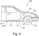
- a fuel filling line 27 is arranged on the battery housing 10, via which fuel 13 can be filled into the fuel tank 12.
- the fuel filler line 27 shown here in dashed lines is connected to a tank filler neck 30 arranged on a fender 28 of a front wheel 29 of the hybrid vehicle 200, via which the fuel tank 12 can be filled with fuel 13.
Landscapes
- Engineering & Computer Science (AREA)
- Transportation (AREA)
- Mechanical Engineering (AREA)
- Life Sciences & Earth Sciences (AREA)
- Sustainable Development (AREA)
- Sustainable Energy (AREA)
- Power Engineering (AREA)
- Chemical & Material Sciences (AREA)
- Combustion & Propulsion (AREA)
- Cooling, Air Intake And Gas Exhaust, And Fuel Tank Arrangements In Propulsion Units (AREA)
- Hybrid Electric Vehicles (AREA)
Description
- Die Erfindung betrifft eine Batterieeinheit für ein Hybridfahrzeug. Ferner betrifft die Erfindung ein Hybridfahrzeug mit einer derartigen Batterieeinheit.
- Hybridfahrzeuge weisen in der Regel sowohl einen Verbrennungsmotor als auch einen Elektromotor zum Antreiben des Kraftfahrzeugs auf. Für den Antrieb mittels Kraftstoff ist in dem Kraftfahrzeug ein Kraftstofftank angeordnet, in welchem der flüssige Kraftstoff gespeichert wird und von welchem aus der flüssige Kraftstoff zu dem Verbrennungsmotor geführt wird. Für den elektrischen Antrieb ist in dem Kraftfahrzeug üblicherweise eine zusätzlich und getrennt zu dem Kraftstofftank angeordnete Batterieeinheit vorgesehen, welche ein oder mehrere Batteriemodule aufweist, in welchen elektrische Energie gespeichert ist. Bei einem solchen Hybridfahrzeug ist die Ausgestaltung des Fahrgestells sehr aufwendig und schwierig, da beide Antriebskonzepte in dem Fahrgestell untergebracht werden müssen. Bislang werden die beiden Antriebskonzepte vollständig separat voneinander in dem Fahrgestell angeordnet, wobei meist die Fahrgestelle für den reinen verbrennungsmotorischen Antrieb verwendet werden und auf aufwendige Art und Weise und mit hohen Kosten die Batterieeinheit in dieses Fahrgestell mit integriert wird.
-
WO 01/79012 A2 - Der Erfindung liegt die Aufgabe zugrunde, eine Batterieeinheit sowie ein Hybridfahrzeug zur Verfügung zu stellen, mittels welchen die Integration beider Antriebskonzepte eines Hybridfahrzeugs in einem Fahrgestell des Hybridfahrzeugs vereinfacht werden kann.
- Die Aufgabe wird erfindungsgemäß mit den Merkmalen der unabhängigen Ansprüche gelöst. Zweckmäßige Ausgestaltungen und vorteilhafte Weiterbildungen der Erfindung sind in den Unteransprüchen angegeben.
- Die Batterieeinheit gemäß der Erfindung zeichnet sich dadurch aus, dass in dem Batteriegehäuse mindestens ein Kraftstofftank angeordnet ist.
- Erfindungsgemäß ist es nunmehr vorgesehen, den Kraftstofftank, in welchem der Kraftstoff für den verbrennungsmotorischen Antrieb des Hybridfahrzeugs gespeichert ist, mit in das Batteriegehäuse der Batterieeinheit zu integrieren. Die Batteriemodule und der Kraftstofftank sind damit in ein und demselben Gehäuse, dem Batteriegehäuse, angeordnet. Damit ist eine besonders platzsparende Anordnung des elektrischen Antriebs zusammen mit dem verbrennungsmotorischen Antrieb möglich. Zudem ist dadurch der Kraftstofftank und die Batterieeinheit nicht mehr separat voneinander an dem Fahrgestell des Hybridfahrzeugs anzuordnen, sondern der Kraftstofftank und die Batterieeinheit können als eine Einheit an dem Fahrgestell angeordnet werden, so dass der Aufwand zur Integration beider Antriebskonzepte in einem Fahrgestell wesentlich reduziert werden kann. Dadurch können die Sicherheitsmaßnahmen wesentlich reduziert werden, da der Kraftstofftank durch das üblicherweise sehr stabil ausgebildete Batteriegehäuse mit geschützt ist. Das Batteriegehäuse ist vorzugsweise derart ausgebildet, dass es den Kraftstofftank zusammen mit den Batteriemodulen vollständig umschließt. Die Batteriemodule und der Kraftstofftank sind vorzugsweise nebeneinander in dem Batteriegehäuse angeordnet. In dem Batteriegehäuse können ein oder mehrere Batteriemodule angeordnet sein. Ferner können in dem Batteriegehäuse auch ein oder mehrere Kraftstofftanks angeordnet sein.
- Dadurch, dass der Kraftstofftank nunmehr durch das Batteriegehäuse geschützt ist, kann der mindestens eine Kraftstofftank aus einem Kunststoffmaterial ausgebildet sein. Der Kraftstofftank ist vorzugsweise bereits durch das speziell gegen Beschädigungen im Falle eines Unfalls des Hybridfahrzeugs ausgelegte Batteriegehäuse geschützt, sodass insbesondere ein Kunststoffmaterial für den Kraftstofftank verwendet werden kann, welches eine geringere Kälteschlagzähigkeit aufweist. Beispielsweise können als Kunststoffmaterial für den Kraftstofftank Polyphthalamide (PPA), Polyketone, Polyphenylensulfid (PPS), Polyoxymethylen (POM) und/oder Polyamid (PA) verwendet werden.
- Durch die Möglichkeit des Einsatzes eines thermoplastischen Kunststoffmaterials für den Kraftstofftank kann der mindestens eine Kraftstofftank vorzugsweise in einem Spritzgussverfahren hergestellt sein. Die Herstellung des Kraftstofftanks kann dadurch mit einem reduzierten Aufwand und geringeren Kosten erfolgen. Ferner können hierbei besonders anforderungsoptimierte Wanddicken des Kraftstofftanks erreicht werden. Ferner können bei einem Einsatz eines Spritzgussverfahrens weitere Bauteile bzw. Funktionselemente, wie beispielsweise Schwallwände oder Schwalltöpfe, bereits bei der Ausbildung des Kraftstofftanks mit in den Kraftstofftank, insbesondere in die Wandung des Kraftstofftanks, eingebracht bzw. integriert werden. Weiter ist es auch möglich, dass der Kraftstofftank in einem Spritzgussverfahren hergestellt ist.
- Der mindestens eine Kraftstofftank und das eine oder die mehreren Batteriemodule sind zusammen vorzugsweise in einem Paket angeordnet, sodass sie eine Einheit ausbilden. Beispielsweise kann der mindestens eine Kraftstofftank mit dem mindestens einem Batteriemodul in einer Reihe hintereinander angeordnet sein. Dadurch ist eine kompakte Anordnung von Kraftstofftank und Batteriemodulen in dem Batteriegehäuse möglich. Vorzugsweise können die ein oder mehreren Kraftstofftanks und die ein oder mehreren Batteriemodule hintereinander gestapelt angeordnet sein. Um insbesondere platzsparend in dem Fahrgestell des Hybridfahrzeugs integriert werden zu können, weist das Batteriegehäuse vorzugsweise eine flache, längliche Ausgestaltung auf, so dass das Batteriegehäuse niedrig aufbaut. In einem derartigen Batteriegehäuse können der Kraftstofftank und die ein oder mehreren Batteriemodule hintereinander gestapelt angeordnet sein.
- Weiter ist es auch möglich, dass Batteriemodule auch übereinander gestapelt angeordnet sind. Somit können ein oder mehrere Reihen von Batteriemodulen in dem Batteriegehäuse angeordnet sein, bei welchem die Batteriemodule sowohl hintereinander als auch übereinander gestapelt angeordnet sein können.
- Um den mindestens einen Kraftstofftank und die ein oder mehreren Batteriemodule möglichst kompakt als ein Paket anordnen zu können, weist der mindestens eine Kraftstofftank vorzugsweise eine Außenkontur auf, welche an eine Außenkontur des mindestens einen Batteriemoduls angepasst sein kann. Ist beispielsweise die Außenkontur der Batteriemodule rechteckförmig ausgebildet, ist auch die Außenkontur des mindestens einen Kraftstofftanks rechteckförmig ausgebildet. Durch die aneinander angepasste Außenkontur können Kraftstofftank und Batteriemodul unmittelbar ohne Platzverluste in dem Batteriegehäuse angeordnet werden. Vorzugsweise kann der Kraftstofftank flächig anliegend an einem Batteriemodul angeordnet sein.
- Der mindestens eine Kraftstofftank ist bevorzugt als Drucktank ausgebildet. Ist der Kraftstofftank als Drucktank ausgebildet, kann das vorzugsweise steif ausgebildete Batteriegehäuse genutzt werden, um mögliche Verformungen des Kraftstofftanks bei einem Überdruck zu reduzieren. Ist der Kraftstofftank als Drucktank ausgebildet, so kann er vorzugsweise für Drücke von bis zu circa +500 mbar ausgelegt sein.
- Zur Stabilisierung der Kraftstofftanks kann der mindestens eine Kraftstofftank ein oder mehrere in Richtung eines Innenraums des Kraftstofftanks ausgebildete Einbuchtungen und/oder mehrere an einer Innenseite des Kraftstofftanks ausgebildete Rippen aufweisen. Mittels der Rippen und/oder Einbuchtungen kann einem in dem Kraftstofftank entstehender Unterdruck und/oder Überdruck entgegengewirkt werden.
- Um im Falle einer Beschädigung der Batteriemodule und/oder des Kraftstofftanks in dem Batteriegehäuse, beispielsweise bei einem Unfall des Hybridfahrzeugs, einen Druckausgleich in dem Batteriegehäuse erreichen zu können, beispielsweise bei einer Erwärmung der beschädigten Batteriemodule und/oder des Kraftstoffs in dem beschädigten Kraftstofftank, erfindungsgemäß weist das Batteriegehäuse mindestens eine Entgasungsöffnung auf.
- Die Entgasungsöffnung ist vorzugsweise an der Frontseitenwand oder Heckseitenwand des Batteriegehäuses ausgebildet, so dass verhindert werden kann, dass heißes Gas und gegebenenfalls in dem Gas entstehende Flammen seitlich in Richtung der Fahrzeugtüren des Hybridfahrzeugs aus dem Batteriegehäuse austreten können. Bevorzugt weist das Batteriegehäuse mehr als eine Entgasungsöffnung auf, über welche unter Druck stehende Luft aus dem Batteriegehäuse entweichen kann. Mittels der Entgasungsöffnung ist ein kontrollierter und effizienter Druckabbau in dem Innenraum des Batteriegehäuses möglich.
- Vorzugsweise ist es vorgesehen, dass das Batteriegehäuse eine erste Entgasungsöffnung und eine zweite Entgasungsöffnung aufweist, wobei die erste Entgasungsöffnung an der Frontseitenwand des Batteriegehäuses und die zweite Entgasungsöffnung an der Heckseitenwand des Batteriegehäuses angeordnet sein kann. Ist sowohl an der Frontseitenwand als auch an der Heckseitenwand des Batteriegehäuses eine Entgasungsöffnung angeordnet, so kann eine Entgasung zu zwei Seiten des Batteriegehäuses erfolgen. Durch die Anordnung der Entgasungsöffnungen an der Frontseitenwand und der Heckseitenwand kann bei einem Überschlagen des Hybridfahrzeuges im Falle eines Unfalls ein Austreten insbesondere von sich in dem Batteriegehäuse ausbreitenden Kraftstoff, wenn der Kraftstofftank beschädigt ist, verhindert werden, da die Entgasungsöffnungen auch bei einer Überschlagsbewegung des Batteriegehäuses zusammen mit dem Hybridfahrzeug ihre Position in Bezug auf ihre Höhe nicht verändern. Ferner kann dadurch verhindert werden, dass aus dem Batteriegehäuse entweichendes Gas oder in dem Gas enthaltende Flammen in Richtung der Seitentüren des Hybridfahrzeugs austreten, so dass auch im Falle eines Unfalls die Fahrzeuginsassen vor dem austretenden Gas und gegebenenfalls entstehenden Flammen geschützt sind.
- Um zusätzlich zu einem Druckausgleich auch eine Flüssigkeitsdichtheit im Bereich der Entgasungsöffnung erreichen zu können, weist die mindestens eine Entgasungsöffnung erfindungsgemäß eine semipermeable Membran auf. Die semipermeable Membran kann sich beispielsweise über den gesamten Öffnungsquerschnitt der Entgasungsöffnung erstrecken, um diese entsprechend für Flüssigkeiten zu schließen und gleichzeitig für Gase, wie Luft, zu öffnen. Vorzugsweise ist an jeder Entgasungsöffnung eine semipermeable Membran angeordnet.
- Um den Abstand zwischen Kraftstofftank und einem in dem Kraftfahrzeug angeordneten Verbrennungsmotor möglichst gering halten zu können, ist der mindestens eine Kraftstofftank bevorzugt benachbart zu der Frontseitenwand angeordnet. Durch eine derartige Positionierung des Kraftstofftanks können die Leitungen zwischen dem Kraftstofftank und dem Verbrennungsmotor möglichst kurz ausgebildet sein. Alternativ ist es aber auch möglich, dass der Kraftstofftank benachbart zu der Heckseitenwand angeordnet ist.
- Bevorzugt ist es ferner vorgesehen, dass ein Aktivkohlefilter in dem Batteriegehäuse angeordnet ist. Der Aktivkohlefilter kann Kohlenwasserstoffe herausfiltern. Bevorzugt ist der Aktivkohlefilter zwischen dem Kraftstofftank und einer Wandung, beispielsweise der Frontseitenwand des Batteriegehäuses angeordnet.
- Zudem ist es möglich, dass zwei oder mehr Kraftstofftanks in dem Batteriegehäuse angeordnet sind, welche hintereinander und/oder übereinander und/oder nebeneinander gestapelt angeordnet sein können. Hierdurch kann auch bei mehreren Kraftstofftanks in dem Batteriegehäuse eine kompakte Anordnung der Kraftstofftanks erreicht werden.
- Die Lösung der erfindungsgemäßen Aufgabe erfolgt ferner mittels eines Hybridfahrzeugs, welches eine wie vorstehend beschriebene, aus- und weitergebildete Batterieeinheit aufweist. In Bezug auf die Vorteile des Hybridfahrzeugs wird auf die zur Batterieeinheit genannten Vorteile verwiesen.
- Bevorzugt kann an einem Kotflügel eines Vorderrads oder eines Hinterrades des Hybridfahrzeugs ein Tankeinfüllstutzen angeordnet, welcher über eine Kraftstoffeinfüllleitung mit dem Kraftstofftank in dem Batteriegehäuse der Batterieeinheit verbunden sein kann. Durch eine derartige Anordnung des Tankeinfüllstutzens kann die Kraftstoffeinfüllleitung kürzer ausgebildet sein, da der Kraftstofftank vorzugsweise in Richtung der Fronseite des Hybridfahrzeugs angeordnet ist.
- Nachfolgend wird die Erfindung unter Bezugnahme auf die anliegenden Zeichnungen anhand bevorzugter Ausführungsformen näher erläutert.
- Es zeigen:
- Fig. 1
- eine schematische Darstellung einer Batterieeinheit gemäß der Erfindung,
- Fig. 2
- eine schematische Schnittdarstellung eines Batteriegehäuses gemäß der Erfindung,
- Fig. 3
- eine schematische Schnittdarstellung eines Kraftstofftanks gemäß der Erfindung, und
- Fig. 4
- eine schematische Darstellung eines Hybridfahrzeugs gemäß der Erfindung.
-
Fig. 1 zeigt schematisch eine Batterieeinheit 100 für ein wie inFig. 4 gezeigtes Hybridfahrzeug 200. - Die Batterieeinheit 100 weist ein Batteriegehäuse 10 auf, innerhalb welchem mehrere Batteriemodule 11 zusammen mit einem Kraftstofftank 12, in welchem flüssiger Kraftstoff 13 gespeichert ist, angeordnet sind. Das Batteriegehäuse 10 umschließt den Kraftstofftank 12 und die Batteriemodule 11, so dass sowohl die Batteriemodule 11 als auch der Kraftstofftank 12 mittels des Batteriegehäuses 10 geschützt angeordnet sind.
- Der Kraftstofftank 12 ist unmittelbar angrenzend an einem der Batteriemodule 11 angeordnet. Der Kraftstofftank 12 ist mit den Batteriemodulen 11 in einer Reihe hintereinander angeordnet. Der Kraftstofftank 12 ist mit den Batteriemodulen 11 in einem Paket angeordnet.
- Anders als bei der hier gezeigten Ausgestaltung ist es auch möglich, dass Batteriemodule 11 nicht nur hintereinander, sondern auch nebeneinander und/oder übereinander gestapelt angeordnet sind. Ferner ist es auch möglich, dass nicht nur ein Kraftstofftank 12 in dem Batteriegehäuse 10 angeordnet ist, sondern es können auch zwei oder mehr Kraftstofftanks 12 in dem Batteriegehäuse 10 angeordnet sein, welche dann hintereinander und/oder übereinander und/oder nebeneinander gestapelt angeordnet sein können.
- Wie in
Fig. 1 zu erkennen ist, weist der Kraftstofftank 12 eine Außenkontur auf, welche an die Außenkontur der Batteriemodule 11 angepasst ist. Sowohl die Batteriemodule 11 als auch der Kraftstofftank 12 sind rechteckförmig bzw. kastenförmig ausgebildet. Der Kraftstofftank 12 weist die gleiche Länge und die gleiche Höhe auf wie die Batteriemodule 11. Lediglich hinsichtlich der Breite unterscheiden sich der Kraftstofftank 12 und die Batteriemodule 11 in ihren Außenabmaßen voneinander, wobei bei der hier gezeigten Ausgestaltung der Kraftstofftank 12 eine größere Breite aufweist als die einzelne Batteriemodule 11. - Die Batteriemodule 11 weisen jeweils ein Gehäuse auf, in welchem vorzugsweise mehrere Batteriezellen angeordnet sind, welche hier nicht gezeigt sind. Die Batteriemodule 11 dienen dazu, dem Hybridfahrzeug 200 elektrische Energie für den elektrischen Antrieb des Hybridfahrzeugs 200 zur Verfügung zu stellen.
- Der Kraftstofftank 12 speichert flüssigen Kraftstoff, wie beispielsweise Benzin, für einen verbrennungsmotorischen Antrieb des Hybridfahrzeugs 200.
- Der Kraftstofftank 12 ist aus einem Kunststoffmaterial ausgebildet, wobei der Kraftstofftank 12 in einem Spritzgussverfahren hergestellt werden kann. Dadurch, dass der Kraftstofftank 12 durch das Batteriegehäuse 10 geschützt ist, kann der Kraftstofftank 12 aus einem Kunststoffmaterial ausgebildet sein, welches insbesondere eine geringe Schlagzähigkeit bzw. Schlagfestigkeit aufweist.
- Ausgebildet ist der Kraftstofftank 12 als Drucktank. Zur Stabilisierung des Kraftstofftanks 12, insbesondere gegenüber Unterdruck, weist der Kraftstofftank 12, wie in der Schnittdarstellung in
Fig. 3 zu erkennen ist, mehrere in Richtung des Innenraumes 14 des Kraftstofftanks 12 gerichtete Einbuchtungen bzw. Rippen 15 auf, welche an einer in Richtung Innenraum 14 gerichteten Innenseite 16 des Kraftstofftanks 12 ausgebildet bzw. angeordnet sind. - Wie in
Fig. 2 gezeigt ist, weist das Batteriegehäuse (10) zwei Entgasungsöffnungen 17, 18 auf, über welche ein Druckausgleich zwischen einem Innenraum 19 des Batteriegehäuses 10 und außerhalb des Batteriegehäuses 10 erfolgen kann. Bei der inFig. 2 gezeigten Ausgestaltung weist das Batteriegehäuse 10 zwei Entgasungsöffnungen 17, 18 auf, wobei die erste Entgasungsöffnung 17 an der Frontseitenwand 23 des Batteriegehäuses 10 und die zweite Entgasungsöffnung 18 an der Heckseitenwand 24 des Batteriegehäuses 10 angeordnet ist. - Die Entgasungsöffnungen 17, 18 an dem Batteriegehäuse 10 sind mittels einer semipermeablen Membran 22 verschlossen, welche Gas, wie Luft, durchlässt und gegenüber Flüssigkeiten sperrt, so dass keine Flüssigkeit in das Batteriegehäuse 10 über die Entgasungsöffnungen 17, 18 eintreten bzw. austreten kann.
- Im Falle eines Anstiegs der Temperatur in dem Kraftstofftank 12 und/oder in dem Batteriemodulen 11 und dadurch in dem Batteriegehäuse 10 kann über die Entgasungsöffnungen 17, 18 Gas, insbesondere Luft, entweichen. Steigt die Temperatur sehr stark an, kann es passieren, dass Kraftstoff 13 aus dem Kraftstofftank 12 in den Innenraum 19 des Batteriegehäuses 10 fließen kann, wie in
Fig. 2 schematisch angedeutet ist, und sich an den Batteriemodulen 11 entzünden kann. Die dabei entstehenden Gase können über die Entgasungsöffnungen 17, 18 des Batteriegehäuses 10 kontrolliert entweichen. Durch die Anordnung einer Entgasungsöffnung 17 an der Frontseitenwand 23 und einer Entgasungsöffnung 18 an der Heckseitenwand 24 des Batteriegehäuses 10 kann das Gas entfernt von den Fahrzeugtüren des Hybridfahrzeugs 200 entweichen. Dadurch kann ein Aussteigen und/oder Bergen von Fahrzeuginsassen im Falle eines Unfalls vereinfacht werden und die Gefahr eines Verletzens der Fahrzeuginsassen durch heißes, ausströmendes Gas reduziert werden. Durch die spezielle Positionierung der Entgasungsöffnungen 17, 18 an dem Batteriegehäuse 10 kann zudem die Gefahr des Auslaufens von Kraftstoff 13 aus dem Innenraum 19 des Batteriegehäuses 10 im Falle eines Überschlages des Hybridfahrzeugs 200 reduziert oder sogar verhindert werden. - Innerhalb des Batteriegehäuses 10 ist der Kraftstofftank 12 unmittelbar benachbart bzw. angrenzend zu der Frontseitenwand 23 des Batteriegehäuses 10 angeordnet, so dass der Kraftstofftank 12 in mit dem Pfeil gekennzeichneten Fahrtrichtung des Hybridfahrzeugs 200 vorne angeordnet ist. Die Batteriemodule 11 sind ausgehend von der Frontseitenwand 23 des Batteriegehäuses 10 hinter dem Kraftstofftank 12 angeordnet.
- Aus dem Batteriegehäuse 10 herausgeführt ist eine Kraftstoffleitung 25, über welche Kraftstoff aus dem Kraftstofftank 12 hin zu einem hier nicht gezeigten Verbrennungsmotor geführt werden kann. Ferner ist aus dem Batteriegehäuse 10 eine elektrische Leitung 26 herausgeführt, welche die Batteriemodule 11 mit einem hier nicht gezeigten Elektromotor innerhalb des Hybridfahrzeugs 200 elektrisch verbinden kann.
- Zudem ist an dem Batteriegehäuse 10 eine Kraftstoffeinfüllleitung 27 angeordnet, über welche Kraftstoff 13 in den Kraftstofftank 12 eingefüllt werden kann. Wie in
Fig. 4 zu erkennen ist, ist die hier gestrichelt dargestellte Kraftstoffeinfüllleitung 27 mit einem an einem Kotflügel 28 eines Vorderrads 29 des Hybridfahrzeugs 200 angeordneten Tankeinfüllstutzen 30 verbunden, über welchen ein Betanken des Kraftstofftanks 12 mit Kraftstoff 13 erfolgen kann. -
- 100
- Batterieeinheit
- 200
- Hybridfahrzeug
- 10
- Batteriegehäuse
- 11
- Batteriemodul
- 12
- Kraftstofftank
- 13
- Kraftstoff
- 14
- Innenraum
- 15
- Einbuchtung/Rippe
- 16
- Innenseite
- 17
- Entgasungsöffnung
- 18
- Entgasungsöffnung
- 19
- Innenraum
- 22
- Semipermeable Membran
- 23
- Frontseitenwand
- 24
- Heckseitenwand
- 25
- Kraftstoffleitung
- 26
- Elektrische Leitung
- 27
- Kraftstoffeinfüllleitung
- 28
- Kotflügel
- 29
- Vorderrad
- 30
- Tankeinfüllstutzen
Claims (13)
- Batterieeinheit (100) für ein Hybridfahrzeug (200), mit einem Batteriegehäuse (10), welches eine in Richtung Frontseite (22) des Hybridfahrzeugs (200) gerichtete Frontseitenwand (23) und eine in Richtung Heckseite des Hybridfahrzeugs (200) gerichtete Heckseitenwand (24) aufweist, und mit mindestens einem in dem Batteriegehäuse (10) angeordneten Batteriemodul (11), wobei in dem Batteriegehäuse (10) mindestens ein Kraftstofftank (12) angeordnet ist, wobei das Batteriegehäuse (10) mindestens eine Entgasungsöffnung (17, 18) für einen kontrollierten Druckabbau in einem Innenraum des Batteriegehäuses aufweist, dadurch gekennzeichnet, dass das Batteriegehäuse (10) den Kraftstofftank (12) zusammen mit dem mindestens einen Batteriemodul (11) vollständig umschließt, wobei die mindestens eine Entgasungsöffnung (17, 18) eine semipermeable Membran aufweist.
- Batterieeinheit (100) nach Anspruch 1, dadurch gekennzeichnet, dass der mindestens eine Kraftstofftank (12) aus einem Kunststoffmaterial ausgebildet ist.
- Batterieeinheit (100) nach Anspruch 2, dadurch gekennzeichnet, dass der mindestens eine Kraftstofftank (12) in einem Spritzgussverfahren oder in einem Blasformverfahren hergestellt ist.
- Batterieeinheit (100) nach einem der Ansprüche 1 bis 3, dadurch gekennzeichnet, dass der mindestens eine Kraftstofftank (12) mit dem mindestens einem Batteriemodul (11) in einer Reihe hintereinander angeordnet ist.
- Batterieeinheit (100) nach einem der Ansprüche 1 bis 4, dadurch gekennzeichnet, dass der mindestens eine Kraftstofftank (12) eine Außenkontur aufweist, welche an eine Außenkontur des mindestens einen Batteriemoduls (11) angepasst ist.
- Batterieeinheit (100) nach einem der Ansprüche 1 bis 5, dadurch gekennzeichnet, dass der mindestens eine Kraftstofftank (12) als Drucktank ausgebildet ist.
- Batterieeinheit (100) nach einem der Ansprüche 1 bis 6, dadurch gekennzeichnet, dass der mindestens eine Kraftstofftank (12) ein oder mehrere in Richtung eines Innenraums (14) des Kraftstofftanks (12) ausgebildete Einbuchtungen (15) und/oder ein oder mehrere an einer Innenseite (16) des Kraftstofftanks (12) ausgebildete Rippen (15) aufweist.
- Batterieeinheit (100) nach einem der Ansprüche 1 bis 7, dadurch gekennzeichnet, dass das Batteriegehäuse (10) eine erste Entgasungsöffnung (17) und eine zweite Entgasungsöffnung (18) aufweist, wobei die erste Entgasungsöffnung (17) an der Frontseitenwand des Batteriegehäuses und die zweite Entgasungsöffnung (18) an der Heckseitenwand (23) des Batteriegehäuses (10) angeordnet ist.
- Batterieeinheit (100) nach einem der Ansprüche 1 bis 8, dadurch gekennzeichnet, dass der mindestens eine Kraftstofftank (12) in dem Batteriegehäuse (10) benachbart zu der Frontseitenwand (23) angeordnet ist.
- Batterieeinheit (100) nach einem der Ansprüche 1 bis 9, dadurch gekennzeichnet, dass ein Aktivkohlefilter in dem Batteriegehäuse (10) angeordnet ist.
- Batterieeinheit (100) nach einem der Ansprüche 1 bis 10, dadurch gekennzeichnet, dass zwei oder mehr Kraftstofftanks (12) in dem Batteriegehäuse (10) angeordnet sind, welche hintereinander und/oder übereinander und/oder nebeneinander gestapelt angeordnet sind.
- Hybridfahrzeug (200), mit einer nach einem der Ansprüche 1 bis 11 ausgebildeten Batterieeinheit (100).
- Hybridfahrzeug (200) nach Anspruch 12, dadurch gekennzeichnet, dass an einem Kotflügel (28) eines Vorderrads (29) oder eines Hinterrades des Hybridfahrzeugs (200) ein Tankeinfüllstutzen (30) angeordnet ist, welcher über eine Kraftstoffeinfüllleitung (27) mit dem Kraftstofftank (12) in dem Batteriegehäuse (10) der Batterieeinheit (100) verbunden ist.
Applications Claiming Priority (2)
| Application Number | Priority Date | Filing Date | Title |
|---|---|---|---|
| DE102018130506.0A DE102018130506A1 (de) | 2018-11-30 | 2018-11-30 | Batterieeinheit sowie Hybridfahrzeug mit einer Batterieeinheit |
| PCT/EP2019/082513 WO2020109273A1 (de) | 2018-11-30 | 2019-11-26 | Batterieeinheit sowie hybridfahrzeug mit einer batterieeinheit |
Publications (3)
| Publication Number | Publication Date |
|---|---|
| EP3887187A1 EP3887187A1 (de) | 2021-10-06 |
| EP3887187C0 EP3887187C0 (de) | 2025-02-26 |
| EP3887187B1 true EP3887187B1 (de) | 2025-02-26 |
Family
ID=68766711
Family Applications (1)
| Application Number | Title | Priority Date | Filing Date |
|---|---|---|---|
| EP19813436.3A Active EP3887187B1 (de) | 2018-11-30 | 2019-11-26 | Batterieeinheit sowie hybridfahrzeug mit einer batterieeinheit |
Country Status (5)
| Country | Link |
|---|---|
| US (1) | US11964556B2 (de) |
| EP (1) | EP3887187B1 (de) |
| CN (1) | CN113226818B (de) |
| DE (1) | DE102018130506A1 (de) |
| WO (1) | WO2020109273A1 (de) |
Families Citing this family (3)
| Publication number | Priority date | Publication date | Assignee | Title |
|---|---|---|---|---|
| DE102020122966A1 (de) | 2020-09-02 | 2022-03-03 | Volkswagen Aktiengesellschaft | Sicherheitssystem für ein Fahrzeug, Verfahren zum Betätigen des Sicherheitssystems, Computerprogrammprodukt und Speichermittel |
| JP7754118B2 (ja) * | 2023-03-09 | 2025-10-15 | トヨタ自動車株式会社 | 車両、制御装置、および、車両制御方法 |
| DE202024105853U1 (de) | 2024-10-11 | 2026-02-19 | Ulrich Bruhnke | Moduleinheit für Elektrofahrzeuge |
Family Cites Families (26)
| Publication number | Priority date | Publication date | Assignee | Title |
|---|---|---|---|---|
| JPS59134556A (ja) * | 1983-01-24 | 1984-08-02 | Shin Kobe Electric Mach Co Ltd | 燃料電池ケ−ス |
| US20010052433A1 (en) | 2000-04-14 | 2001-12-20 | Harris Donald B. | Hybrid power supply module |
| JP2005116358A (ja) * | 2003-10-08 | 2005-04-28 | Nissan Motor Co Ltd | 燃料電池自動車におけるガス漏れ検知装置 |
| FR2877650B1 (fr) * | 2004-11-05 | 2008-07-04 | Marwal Systems Snc | Dispositif de ventilation de reservoir |
| JP2007179775A (ja) | 2005-12-27 | 2007-07-12 | Kyocera Corp | 携帯電子機器、電池パック及び携帯電子機器の制御方法 |
| JP2007294293A (ja) | 2006-04-26 | 2007-11-08 | Canon Inc | 燃料電池装置 |
| JP2007320331A (ja) * | 2006-05-30 | 2007-12-13 | Toyota Motor Corp | ハイブリッド車両 |
| JP2008155880A (ja) * | 2006-12-26 | 2008-07-10 | Mazda Motor Corp | 車両の車体構造 |
| JP5360689B2 (ja) | 2009-09-24 | 2013-12-04 | スズキ株式会社 | 車両の高電圧ケーブルの配策構造 |
| JP2011111124A (ja) | 2009-11-30 | 2011-06-09 | Mazda Motor Corp | 車両の後部構造 |
| DE102010007414B4 (de) * | 2010-02-10 | 2016-09-15 | Magna Steyr Fahrzeugtechnik Ag & Co. Kg | Einbaumodul für ein Hybridfahrzeug |
| DE102010035553A1 (de) * | 2010-08-26 | 2012-03-01 | Jungheinrich Aktiengesellschaft | Flurförderzeug mit einem Batterieaufnahmeraum |
| FR2976252A1 (fr) * | 2011-06-09 | 2012-12-14 | Peugeot Citroen Automobiles Sa | Dispositif de montage d'elements mecaniques et de canalisations sous la caisse d'un vehicule automobile |
| US8779622B2 (en) * | 2011-06-30 | 2014-07-15 | GM Global Technology Operations LLC | Customizable energy system and vehicle |
| KR101417306B1 (ko) * | 2012-07-30 | 2014-07-09 | 기아자동차주식회사 | 차량용 배터리팩 |
| JP5810058B2 (ja) | 2012-09-18 | 2015-11-11 | 本田技研工業株式会社 | ハイブリッド車両 |
| DE102012022346B4 (de) | 2012-11-15 | 2018-03-22 | Mann+Hummel Gmbh | Batterie-Gehäuse |
| US9586498B2 (en) | 2013-08-02 | 2017-03-07 | Komatsu Ltd. | Battery for work vehicle and battery-type work vehicle |
| WO2015170094A1 (en) | 2014-05-07 | 2015-11-12 | Bae Systems Plc | Liquid storage system |
| JP6314757B2 (ja) * | 2014-09-04 | 2018-04-25 | 日産自動車株式会社 | 電動車両の車体後部構造 |
| TR201811522T4 (tr) | 2014-10-20 | 2018-09-21 | PFW Aerospace GmbH | Mesanesiz yakıt tankı. |
| DE102014118654A1 (de) * | 2014-12-15 | 2016-06-16 | Kautex Textron Gmbh & Co. Kg | Behälter aus thermoplastischem Kunststoff sowie Verfahren zur Herstellung des Behälters |
| WO2018047677A1 (ja) | 2016-09-09 | 2018-03-15 | 本田技研工業株式会社 | 鞍乗型車両のバッテリケース |
| IL250368B (en) | 2017-01-30 | 2021-08-31 | Beth El Zikhron Yaaqov Ind Ltd | Method and device for extending the driving range of a hybrid vehicle |
| US10787203B2 (en) * | 2018-01-03 | 2020-09-29 | Ford Global Technologies, Llc | Hybrid energy storage and delivery devices for hybrid electric vehicles |
| DE102018105530A1 (de) * | 2018-03-09 | 2019-09-26 | Stöbich Technology Gmbh | Akku-Transportvorrichtung für einen Akkumulator |
-
2018
- 2018-11-30 DE DE102018130506.0A patent/DE102018130506A1/de active Pending
-
2019
- 2019-11-26 CN CN201980079411.5A patent/CN113226818B/zh active Active
- 2019-11-26 US US17/297,739 patent/US11964556B2/en active Active
- 2019-11-26 EP EP19813436.3A patent/EP3887187B1/de active Active
- 2019-11-26 WO PCT/EP2019/082513 patent/WO2020109273A1/de not_active Ceased
Also Published As
| Publication number | Publication date |
|---|---|
| WO2020109273A1 (de) | 2020-06-04 |
| CN113226818A (zh) | 2021-08-06 |
| CN113226818B (zh) | 2023-10-20 |
| EP3887187A1 (de) | 2021-10-06 |
| US11964556B2 (en) | 2024-04-23 |
| US20220041052A1 (en) | 2022-02-10 |
| EP3887187C0 (de) | 2025-02-26 |
| DE102018130506A1 (de) | 2020-06-04 |
Similar Documents
| Publication | Publication Date | Title |
|---|---|---|
| EP2242663B1 (de) | Kraftstoffbehälter für kraftfahrzeuge aus thermoplastischem kunststoff | |
| DE102013204087A1 (de) | Entgasungssystem für Batteriemodule | |
| DE102013216071A1 (de) | Galvanisches System umfassend eine Mehrzahl von galvanischen Zellen und eine Entgasungseinrichtung | |
| EP3661794B1 (de) | Ventilsystem für einen kraftstofftank | |
| EP2337710B1 (de) | Gasgenerator für ein airbagmodul | |
| EP3230109B1 (de) | Einfüllsystem an einem kraftfahrzeug mit wenigstens zwei vorratstanks für flüssige oder gasförmige betriebsstoffe | |
| DE102009039079A1 (de) | Tankanordnung | |
| DE102018130506A1 (de) | Batterieeinheit sowie Hybridfahrzeug mit einer Batterieeinheit | |
| EP3433120A1 (de) | Betriebsflüssigkeitsbehälter mit versteifungselement und verfahren zum herstellen eines betriebsflüssigkeitsbehälters | |
| WO2021043984A1 (de) | Energiespeicher-bodengruppe für einen kraftwagen | |
| DE102021131908A1 (de) | Batteriemodul mit Zellentgasungsöffnungen | |
| EP3642528B1 (de) | Tank eines kraftfahrzeuges mit volumenelement | |
| DE102015014558A1 (de) | Vorrichtung zur Entgasung einer Hochvoltbatterie | |
| DE102012022393A1 (de) | Kraftstoffeinfülleinrichtung | |
| DE102008014363A1 (de) | Belüftung für einen Reduktionsmittelbehälter | |
| EP3368366B1 (de) | Kraftstoffbehälter mit einlassrückschlagventil | |
| DE102010049644A1 (de) | Kraftstoffbehälter für Kfz | |
| DE102010055184A1 (de) | Entlüftungsvorrichtung für Flüssigkeitsbehälter, insbesondere für Flüssigkeitsbehälter für eine wässrige Harnstofflösung | |
| EP1504943B1 (de) | Kraftstoffbehälter mit Ausperlbehälter für ein Kraftfahrzeug | |
| DE20003652U1 (de) | Strömungsleitvorrichtung zur Führung mindestens eines Gasstroms zur Füllung eines Gassacks und Airbagmodul | |
| EP2176096B1 (de) | Airbagmodul für ein kraftfahrzeug | |
| WO2004026608A1 (de) | Lüftungseinrichtung für kraftstofftanks | |
| DE102016204770A1 (de) | Ent- und/oder Belüftungsventil für einen Betriebsflüssigkeitsbehälter | |
| DE102020110700A1 (de) | Batterie für ein Kraftfahrzeug sowie Verfahren zum Herstellen einer Batterie für ein Kraftfahrzeug | |
| DE102022101329A1 (de) | Kombination eines Verteilers und eines Ausgleichsbehälters für ein Temperiersystem eines Kraftfahrzeugs |
Legal Events
| Date | Code | Title | Description |
|---|---|---|---|
| STAA | Information on the status of an ep patent application or granted ep patent |
Free format text: STATUS: UNKNOWN |
|
| STAA | Information on the status of an ep patent application or granted ep patent |
Free format text: STATUS: THE INTERNATIONAL PUBLICATION HAS BEEN MADE |
|
| PUAI | Public reference made under article 153(3) epc to a published international application that has entered the european phase |
Free format text: ORIGINAL CODE: 0009012 |
|
| STAA | Information on the status of an ep patent application or granted ep patent |
Free format text: STATUS: REQUEST FOR EXAMINATION WAS MADE |
|
| 17P | Request for examination filed |
Effective date: 20210602 |
|
| AK | Designated contracting states |
Kind code of ref document: A1 Designated state(s): AL AT BE BG CH CY CZ DE DK EE ES FI FR GB GR HR HU IE IS IT LI LT LU LV MC MK MT NL NO PL PT RO RS SE SI SK SM TR |
|
| DAV | Request for validation of the european patent (deleted) | ||
| DAX | Request for extension of the european patent (deleted) | ||
| STAA | Information on the status of an ep patent application or granted ep patent |
Free format text: STATUS: EXAMINATION IS IN PROGRESS |
|
| 17Q | First examination report despatched |
Effective date: 20220721 |
|
| P01 | Opt-out of the competence of the unified patent court (upc) registered |
Effective date: 20230601 |
|
| GRAP | Despatch of communication of intention to grant a patent |
Free format text: ORIGINAL CODE: EPIDOSNIGR1 |
|
| STAA | Information on the status of an ep patent application or granted ep patent |
Free format text: STATUS: GRANT OF PATENT IS INTENDED |
|
| RIC1 | Information provided on ipc code assigned before grant |
Ipc: B60L 50/64 20190101ALN20241014BHEP Ipc: B60L 50/60 20190101ALN20241014BHEP Ipc: B60K 15/063 20060101ALI20241014BHEP Ipc: B60K 1/04 20190101AFI20241014BHEP |
|
| RIC1 | Information provided on ipc code assigned before grant |
Ipc: B60L 50/64 20190101ALN20241031BHEP Ipc: B60L 50/60 20190101ALN20241031BHEP Ipc: B60K 15/063 20060101ALI20241031BHEP Ipc: B60K 1/04 20190101AFI20241031BHEP |
|
| INTG | Intention to grant announced |
Effective date: 20241111 |
|
| GRAS | Grant fee paid |
Free format text: ORIGINAL CODE: EPIDOSNIGR3 |
|
| GRAA | (expected) grant |
Free format text: ORIGINAL CODE: 0009210 |
|
| STAA | Information on the status of an ep patent application or granted ep patent |
Free format text: STATUS: THE PATENT HAS BEEN GRANTED |
|
| AK | Designated contracting states |
Kind code of ref document: B1 Designated state(s): AL AT BE BG CH CY CZ DE DK EE ES FI FR GB GR HR HU IE IS IT LI LT LU LV MC MK MT NL NO PL PT RO RS SE SI SK SM TR |
|
| REG | Reference to a national code |
Ref country code: GB Ref legal event code: FG4D Free format text: NOT ENGLISH |
|
| REG | Reference to a national code |
Ref country code: CH Ref legal event code: EP |
|
| REG | Reference to a national code |
Ref country code: DE Ref legal event code: R096 Ref document number: 502019013002 Country of ref document: DE |
|
| REG | Reference to a national code |
Ref country code: IE Ref legal event code: FG4D Free format text: LANGUAGE OF EP DOCUMENT: GERMAN |
|
| U01 | Request for unitary effect filed |
Effective date: 20250304 |
|
| P04 | Withdrawal of opt-out of the competence of the unified patent court (upc) registered |
Free format text: CASE NUMBER: APP_11426/2025 Effective date: 20250308 |
|
| U07 | Unitary effect registered |
Designated state(s): AT BE BG DE DK EE FI FR IT LT LU LV MT NL PT RO SE SI Effective date: 20250312 |
|
| PG25 | Lapsed in a contracting state [announced via postgrant information from national office to epo] |
Ref country code: RS Free format text: LAPSE BECAUSE OF FAILURE TO SUBMIT A TRANSLATION OF THE DESCRIPTION OR TO PAY THE FEE WITHIN THE PRESCRIBED TIME-LIMIT Effective date: 20250526 |
|
| PG25 | Lapsed in a contracting state [announced via postgrant information from national office to epo] |
Ref country code: PL Free format text: LAPSE BECAUSE OF FAILURE TO SUBMIT A TRANSLATION OF THE DESCRIPTION OR TO PAY THE FEE WITHIN THE PRESCRIBED TIME-LIMIT Effective date: 20250226 |
|
| PG25 | Lapsed in a contracting state [announced via postgrant information from national office to epo] |
Ref country code: ES Free format text: LAPSE BECAUSE OF FAILURE TO SUBMIT A TRANSLATION OF THE DESCRIPTION OR TO PAY THE FEE WITHIN THE PRESCRIBED TIME-LIMIT Effective date: 20250226 |
|
| PG25 | Lapsed in a contracting state [announced via postgrant information from national office to epo] |
Ref country code: NO Free format text: LAPSE BECAUSE OF FAILURE TO SUBMIT A TRANSLATION OF THE DESCRIPTION OR TO PAY THE FEE WITHIN THE PRESCRIBED TIME-LIMIT Effective date: 20250526 Ref country code: IS Free format text: LAPSE BECAUSE OF FAILURE TO SUBMIT A TRANSLATION OF THE DESCRIPTION OR TO PAY THE FEE WITHIN THE PRESCRIBED TIME-LIMIT Effective date: 20250626 |
|
| PG25 | Lapsed in a contracting state [announced via postgrant information from national office to epo] |
Ref country code: HR Free format text: LAPSE BECAUSE OF FAILURE TO SUBMIT A TRANSLATION OF THE DESCRIPTION OR TO PAY THE FEE WITHIN THE PRESCRIBED TIME-LIMIT Effective date: 20250226 |
|
| PG25 | Lapsed in a contracting state [announced via postgrant information from national office to epo] |
Ref country code: GR Free format text: LAPSE BECAUSE OF FAILURE TO SUBMIT A TRANSLATION OF THE DESCRIPTION OR TO PAY THE FEE WITHIN THE PRESCRIBED TIME-LIMIT Effective date: 20250527 |
|
| PG25 | Lapsed in a contracting state [announced via postgrant information from national office to epo] |
Ref country code: SM Free format text: LAPSE BECAUSE OF FAILURE TO SUBMIT A TRANSLATION OF THE DESCRIPTION OR TO PAY THE FEE WITHIN THE PRESCRIBED TIME-LIMIT Effective date: 20250226 |
|
| PG25 | Lapsed in a contracting state [announced via postgrant information from national office to epo] |
Ref country code: CZ Free format text: LAPSE BECAUSE OF FAILURE TO SUBMIT A TRANSLATION OF THE DESCRIPTION OR TO PAY THE FEE WITHIN THE PRESCRIBED TIME-LIMIT Effective date: 20250226 |
|
| PG25 | Lapsed in a contracting state [announced via postgrant information from national office to epo] |
Ref country code: SK Free format text: LAPSE BECAUSE OF FAILURE TO SUBMIT A TRANSLATION OF THE DESCRIPTION OR TO PAY THE FEE WITHIN THE PRESCRIBED TIME-LIMIT Effective date: 20250226 |
|
| U20 | Renewal fee for the european patent with unitary effect paid |
Year of fee payment: 7 Effective date: 20251105 |
|
| PLBE | No opposition filed within time limit |
Free format text: ORIGINAL CODE: 0009261 |
|
| STAA | Information on the status of an ep patent application or granted ep patent |
Free format text: STATUS: NO OPPOSITION FILED WITHIN TIME LIMIT |
|
| 26N | No opposition filed |
Effective date: 20251127 |