EP3887115B1 - Procede d'impregnation d'un materiau fibreux en lit fluidise interpenetre - Google Patents
Procede d'impregnation d'un materiau fibreux en lit fluidise interpenetre Download PDFInfo
- Publication number
- EP3887115B1 EP3887115B1 EP19842788.2A EP19842788A EP3887115B1 EP 3887115 B1 EP3887115 B1 EP 3887115B1 EP 19842788 A EP19842788 A EP 19842788A EP 3887115 B1 EP3887115 B1 EP 3887115B1
- Authority
- EP
- European Patent Office
- Prior art keywords
- process according
- powder
- tension roller
- rovings
- series
- Prior art date
- Legal status (The legal status is an assumption and is not a legal conclusion. Google has not performed a legal analysis and makes no representation as to the accuracy of the status listed.)
- Active
Links
Images


Classifications
-
- B—PERFORMING OPERATIONS; TRANSPORTING
- B29—WORKING OF PLASTICS; WORKING OF SUBSTANCES IN A PLASTIC STATE IN GENERAL
- B29B—PREPARATION OR PRETREATMENT OF THE MATERIAL TO BE SHAPED; MAKING GRANULES OR PREFORMS; RECOVERY OF PLASTICS OR OTHER CONSTITUENTS OF WASTE MATERIAL CONTAINING PLASTICS
- B29B15/00—Pretreatment of the material to be shaped, not covered by groups B29B7/00 - B29B13/00
- B29B15/08—Pretreatment of the material to be shaped, not covered by groups B29B7/00 - B29B13/00 of reinforcements or fillers
- B29B15/10—Coating or impregnating independently of the moulding or shaping step
- B29B15/12—Coating or impregnating independently of the moulding or shaping step of reinforcements of indefinite length
- B29B15/122—Coating or impregnating independently of the moulding or shaping step of reinforcements of indefinite length with a matrix in liquid form, e.g. as melt, solution or latex
- B29B15/125—Coating or impregnating independently of the moulding or shaping step of reinforcements of indefinite length with a matrix in liquid form, e.g. as melt, solution or latex by dipping
-
- B—PERFORMING OPERATIONS; TRANSPORTING
- B29—WORKING OF PLASTICS; WORKING OF SUBSTANCES IN A PLASTIC STATE IN GENERAL
- B29B—PREPARATION OR PRETREATMENT OF THE MATERIAL TO BE SHAPED; MAKING GRANULES OR PREFORMS; RECOVERY OF PLASTICS OR OTHER CONSTITUENTS OF WASTE MATERIAL CONTAINING PLASTICS
- B29B15/00—Pretreatment of the material to be shaped, not covered by groups B29B7/00 - B29B13/00
- B29B15/08—Pretreatment of the material to be shaped, not covered by groups B29B7/00 - B29B13/00 of reinforcements or fillers
- B29B15/10—Coating or impregnating independently of the moulding or shaping step
- B29B15/12—Coating or impregnating independently of the moulding or shaping step of reinforcements of indefinite length
- B29B15/14—Coating or impregnating independently of the moulding or shaping step of reinforcements of indefinite length of filaments or wires
-
- B—PERFORMING OPERATIONS; TRANSPORTING
- B29—WORKING OF PLASTICS; WORKING OF SUBSTANCES IN A PLASTIC STATE IN GENERAL
- B29K—INDEXING SCHEME ASSOCIATED WITH SUBCLASSES B29B, B29C OR B29D, RELATING TO MOULDING MATERIALS OR TO MATERIALS FOR MOULDS, REINFORCEMENTS, FILLERS OR PREFORMED PARTS, e.g. INSERTS
- B29K2101/00—Use of unspecified macromolecular compounds as moulding material
- B29K2101/12—Thermoplastic materials
-
- B—PERFORMING OPERATIONS; TRANSPORTING
- B29—WORKING OF PLASTICS; WORKING OF SUBSTANCES IN A PLASTIC STATE IN GENERAL
- B29K—INDEXING SCHEME ASSOCIATED WITH SUBCLASSES B29B, B29C OR B29D, RELATING TO MOULDING MATERIALS OR TO MATERIALS FOR MOULDS, REINFORCEMENTS, FILLERS OR PREFORMED PARTS, e.g. INSERTS
- B29K2105/00—Condition, form or state of moulded material or of the material to be shaped
- B29K2105/06—Condition, form or state of moulded material or of the material to be shaped containing reinforcements, fillers or inserts
- B29K2105/08—Condition, form or state of moulded material or of the material to be shaped containing reinforcements, fillers or inserts of continuous length, e.g. cords, rovings, mats, fabrics, strands or yarns
- B29K2105/10—Cords, strands or rovings, e.g. oriented cords, strands or rovings
Definitions
- the present invention relates to a method of manufacturing a fibrous material pre-impregnated with thermoplastic polymer.
- the invention relates to a process for manufacturing a pre-impregnated fibrous material comprising an impregnation step in powder form for the preparation of a pre-impregnated fibrous material, in particular in an interpenetrated fluidized bed, in with a view to obtaining ribbons of pre-impregnated fibrous material, of calibrated dimensions, directly usable for the manufacture of three-dimensional composite parts.
- This disturbance which can be managed and controlled for a strand of fibers or even several strands of fibers separated by a certain distance, is not easily and stable for a sheet of strands of fibers stuck to each other. Also, when assembling rovings of fibers before or at the level of the fluidized bed, we generally observe an inhomogeneity in the transport of powder by the layer of rovings; the powder content is generally lower on the fiber rovings located in the center of the web.
- one of the disadvantages of this method lies in the total width of the impregnation line, especially if we want to multiply the wicks in parallel to improve the productivity of the line.
- This maximum width is induced not only by the width of each strand of fibers in the fluidization bath but also by the inter-wick distance necessary to avoid disturbing the fluidization of a fiber that is too close to its close neighbor. In the most disturbed cases, it is possible to double the width of the impregnation line due to this inter-wick space.
- JP H07 40341 describes a process for impregnating a fiberglass fibrous material with vinyl chloride in powder form, said fibrous material being separated into two groups, each group circulating separately on two moorings and the two groups being united on the third jamming.
- the two groups of wicks do not have the same residence time in the tank and therefore cannot be impregnated in the same way.
- this rommement can take place during the powder impregnation step, just after this step, or at the outlet of the tank containing the fluidized bed, or even after the step of melting the powder and impregnating the fibers with the molten resin.
- the fibers are oriented with a particular angle different from angle 0 corresponding to their initial orientation modeled on their axis of movement in the impregnation process.
- a misalignment of the fibers in the plane (horizontal) and/or out of the plane (vertical) of the web of strands of fibers can result from this induced angle, this misalignment freezing when the thermoplastic resin cools and can no longer be corrected subsequently.
- the invention therefore aims to remedy at least one of the disadvantages of the prior art.
- the invention aims in particular to propose an innovative method of manufacturing a large number of wicks individually impregnated in parallel, comprising the same rate of dry powder, while maintaining an installation whose width is close to the width of all of the locks impregnated with powder.
- this impregnation will be homogeneous, that is to say that the powder will be regularly distributed over the entire width of each of said wicks.
- the assembly will take place after the impregnation step.
- the parallel impregnation device of the rovings with the powder will allow to maintain the parallelism of the axis of symmetry of the bits impregnated with the powder.
- these fiber rovings are impregnated using an impregnation process in a tank comprising a thermoplastic polymer in powder form, particularly in a fluidized bed, the dimensions of which are minimal and still allowing homogeneous impregnation of the roving and in particular without disturbing a given strand of fibers on its closest neighbors.
- the reinforcing fibers will be impregnated with thermoplastic polymer at the core and with a low and controlled porosity rate, this core impregnation of the fiber rovings taking place after the powder melting phase but first requiring a homogeneous impregnation of the locks with the powder.
- the invention relates to a method of manufacturing a pre-impregnated fibrous material comprising a step of pre-impregnation of rovings of parallel reinforcing fibers, said rovings being divided into two or more groups of fiber rovings which will constitute the ribbons or the final tablecloth, each group of strands running separately and interpenetrating on a system of two or more series of restraints in the tank comprising a thermoplastic polymer in powder form, in particular in a fluidized bed.
- the average diameter D50 by volume of the thermoplastic polymer powder particles is between 30 and 300 ⁇ m, in particular 50 to 200 ⁇ m, more particularly 70 to 200 ⁇ m.
- width used in the expressions "tank width” or "line width” designates the dimension of the element considered (here the tank in the first case and the line in the second case) measured in the horizontal plane and in the direction transverse to the direction of travel of the wick in the process.
- parallel bits means that the axes of symmetry of the bits are parallel to each other.
- the expression “residence time in the powder” means the time during which the wick is in contact with said powder in said at least one tank (10).
- dry means that said at least one thermoplastic polymer matrix is in powder form in said at least one tank and therefore devoid of water or a solvent in which it would be in suspension or dispersion or emulsion, apart from the humidity level naturally present in said thermoplastic powder.
- Only air or a neutral gas can be present in said at least one tank.
- homogeneous means that the impregnation is uniform across the width of the strands.
- fibrous material means an assembly of reinforcing fibers. Before being shaped, it is in the form of strands. After its shaping, it is in the form of strips (or tapes) composed of one or more wicks or ribbons or sheets obtained by assembling a large number of wicks, that is to say greater than 9 wicks.
- the method according to the invention excludes any electrostatic process with voluntary charging.
- the tanks are located in the longitudinal alignment of the wicks or the tanks are superimposed.
- said at least one tank (10) corresponds to at least one fluidized bed (11).
- the pre-impregnation step is carried out using a single tank (10).
- the pre-impregnation step is carried out by means of a single tank (10) comprising a fluidized bed (11).
- said pre-impregnation step is carried out in a tank by spraying with a gun.
- the inventors have therefore unexpectedly found that the division of the wicks into several groups of individualized parallel wicks, each group of individualized parallel wicks running on a system of series of lashings, the number of series of lashings corresponding to the number of groups of wick, a single group moving on a single series of clamps and the different groups being interpenetrated with each other, while controlling the residence time, allowed a homogeneous pre-impregnation and allowed in a second step after the fusion of the powder, d obtain thoroughly impregnated wicks with a low and controlled porosity rate in each wick without the need to increase the width of the tank comprising the impregnation powder.
- the inventors found that the division of the rovings into several groups of parallel rovings, while generating sufficient space between each strand of fibers belonging to a given group, the different groups being interpenetrated with each other, made it possible not to not disrupt the fluidization of the powder and therefore ensure that each of the wicks is not subject to the influence of its closest neighbors, while controlling the residence time in the powder of each wick and therefore allowing the powder rate is constant from one strand to the next.
- thermoplastic or thermoplastic polymer
- a material that is generally solid at room temperature which may be semi-crystalline or amorphous, and which softens when the temperature increases, in particular after passing its glass transition temperature (Tg). and flows at a higher temperature when it is amorphous, or can present a clear melting upon passing its so-called melting temperature (Tf) when it is semi-crystalline, and which becomes solid again upon a decrease in temperature below its crystallization temperature (for a semi-crystalline) and below its glass transition temperature (for an amorphous).
- Tg glass transition temperature
- Tf melting temperature
- the Tg and Tf are determined by differential scanning calorimetry (DSC) according to standard 11357-2:2013 and 11357-3:2013 respectively.
- thermoplastic polymer or a mixture of thermoplastic polymers.
- This polymer or mixture of thermoplastic polymers is crushed in powder form, in order to be able to use it in a device such as a tank, in particular in a fluidized bed.
- the device in the form of a tank, particularly in a fluidized bed, can be open or closed.
- thermoplastic polymer or mixture of thermoplastic polymers further comprises carbonaceous fillers, in particular carbon black or carbonaceous nanofillers, preferably chosen from carbonaceous nanofillers, in particular graphenes and/or carbon nanotubes and /or carbon nanofibrils or mixtures thereof.
- carbonaceous fillers in particular carbon black or carbonaceous nanofillers, preferably chosen from carbonaceous nanofillers, in particular graphenes and/or carbon nanotubes and /or carbon nanofibrils or mixtures thereof.
- said thermoplastic polymer comprises at least one additive, in particular chosen from a catalyst, an antioxidant, a thermal stabilizer, a UV stabilizer, a light stabilizer, a lubricant, a filler, a plasticizer, a flame retardant, a nucleating agent , a chain extender and a colorant or a mixture thereof.
- a catalyst an antioxidant, a thermal stabilizer, a UV stabilizer, a light stabilizer, a lubricant, a filler, a plasticizer, a flame retardant, a nucleating agent , a chain extender and a colorant or a mixture thereof.
- thermoplastic polymer or mixture of thermoplastic polymers may further comprise liquid crystal polymers or cyclized poly(butylene terephthalate), or mixtures containing them, such as the CBT100 resin sold by the company CYCLICS CORPORATION.
- liquid crystal polymers or cyclized poly(butylene terephthalate), or mixtures containing them such as the CBT100 resin sold by the company CYCLICS CORPORATION.
- thermoplastic polymer when said thermoplastic polymer is mixed, it is added to the tank in the form of powder obtained beforehand by “dry blend” or compound or directly into the tank in the form of “dry blend”.
- the mixture is a mixture of PEKK and PEI.
- polymer P1 and P2 when said polymer is a mixture of two polymers P1 and P2, the proportion by weight of polymer P1 and P2 is between 1-99% and 99-1%.
- the PEKK/PEI mixture is comprised from 90-10% to 60-40% by weight, in particular from 90-10% to 70-30% by weight.
- the thermoplastic polymer may correspond to the final non-reactive polymer which will impregnate the fibrous material or to a reactive prepolymer, which will also impregnate the fibrous material, but is likely to react on itself or with another prepolymer, depending on the ends of the chain carried by said prepolymer, after impregnation, or even with a chain extender and in particular during heating at the level of a heating calender.
- said prepolymer may comprise or consist of at least one reactive prepolymer (polyamide) carrying on the same chain (that is to say on the same prepolymer), two terminal functions X' and Y' respectively co-reactive functions with each other by condensation, more particularly with X' and Y' being amine and carboxy or carboxy and amine respectively.
- said prepolymer may comprise or consist of at least two mutually reactive polyamide prepolymers each carrying two identical terminal functions X' or Y' respectively (identical for the same prepolymer and different between the two prepolymers), said X' function of a prepolymer being able to react only with said Y' function of the other prepolymer, in particular by condensation, more particularly with X' and Y' being amine and carboxy or carboxy and amine respectively.
- said prepolymer may comprise or consist of at least one prepolymer of said thermoplastic polyamide polymer, carrying n terminal reactive functions X, chosen from: - NH2, -CO2H and -OH, preferably NH2 and -CO2H with n being 1 to 3, preferably 1 to 2, more preferably 1 or 2, more particularly 2 and at least one Y-A'-Y chain extender, with A' being a hydrocarbon biradical, of non-polymeric structure, carrier of 2 identical terminal reactive functions Y, reactive by polyaddition with at least one function X of said prepolymer a1), preferably of molecular mass less than 500, more preferably less than 400.
- n terminal reactive functions X chosen from: - NH2, -CO2H and -OH, preferably NH2 and -CO2H with n being 1 to 3, preferably 1 to 2, more preferably 1 or 2, more particularly 2 and at least one Y-A'-Y chain extender, with A' being a hydrocarbon bi
- the number average molecular mass Mn of said final polymer of the thermoplastic matrix is preferably in a range going from 10,000 to 40,000, preferably from 12,000 to 30,000. These Mn values can correspond to inherent viscosities greater than or equal to 0.8 such as determined in m-cresol according to standard ISO 307:2007 but by changing the solvent (use of m-cresol instead of sulfuric acid and the temperature being 20°C).
- Said reactive prepolymers according to the two options mentioned above have a number average molecular mass Mn ranging from 500 to 10,000, preferably from 1000 to 6000, in particular from 2500 to 6000.
- the Mn are determined in particular by calculation from the rate of terminal functions determined by potentiometric titration in solution and the functionality of said prepolymers.
- the Mn masses can also be determined by size exclusion chromatography or by NMR.
- the polyamide may be a homopolyamide or a copolyamide or a mixture thereof.
- the polymers constituting the matrix are chosen from polyamides (PA), in particular chosen from aliphatic polyamides, in particular PA11 and PA12, cycloaliphatic polyamides, and semi-aromatic polyamides (polyphthalamides) optionally modified by urea units, and their copolymers, Polymethyl methacrylate (PPMA) and its copolymers, Polyether imides (PEI), Poly(phenylene sulfide) (PPS), Poly(phenylene sulfone) (PPSU), Polyetherketoneketone ( PEKK), Polyetheretherketone (PEEK), fluoropolymers such as poly(vinylidene fluoride) (PVDF).
- PA polyamides
- PA polyamides
- PA polyamides
- PA11 and PA12 aliphatic polyamides
- PA11 and PA12 cycloaliphatic polyamides
- semi-aromatic polyamides polyphthalamides
- PPMA Polymethyl methacrylate
- PEI
- VDF content must be greater than 80% by mass, or even better 90% by mass, to ensure good mechanical resistance to the structural part, especially when it is subjected to thermal and chemical stresses.
- the comonomer may be a fluorinated monomer such as, for example, vinyl fluoride.
- PAEK PolyArylEtherKetone
- PAEK PolyArylEtherKetone
- PEK polyether ketones
- PEEK poly(ether ether ketone) PEEK
- PEKK poly(ether ketone ketone) PEKK
- PAs Tg high glass transition temperature PAs Tg
- thermoplastic polymer is a polymer whose glass transition temperature is such that Tg ⁇ 80°C or a semi-crystalline polymer whose melting temperature Tf ⁇ 150°C.
- T is terephthalic acid
- MXD is m-xylylene diamine
- MPMD is methylpentamethylene diamine
- BAC is bis(aminomethyl)cyclohexane.
- fibers constituting said fibrous material are in particular fibers of mineral, organic or plant origin.
- fibers of mineral origin we can cite carbon fibers, glass fibers, basalt fibers, silica fibers, or silicon carbide fibers for example.
- fibers of organic origin mention may be made of fibers based on thermoplastic or thermosetting polymer, such as semi-aromatic polyamide fibers, aramid fibers or polyolefin fibers for example.
- they are based on an amorphous thermoplastic polymer and have a glass transition temperature Tg greater than the Tg of the polymer or mixture of thermoplastic polymer constituting the impregnation matrix when the latter is amorphous, or greater than the Tf of the polymer or mixture of thermoplastic polymer constituting the impregnation matrix when the latter is semi-crystalline.
- they are based on semi-crystalline thermoplastic polymer and have a melting temperature Tf greater than the Tg of the polymer or mixture of thermoplastic polymer constituting the impregnation matrix when the latter is amorphous, or greater than the Tf of the polymer or mixture of thermoplastic polymer constituting the impregnation matrix when the latter is semi-crystalline.
- the organic fibers constituting the fibrous material there is no risk of melting for the organic fibers constituting the fibrous material during impregnation by the thermoplastic matrix of the final composite.
- the fibers of plant origin mention may be made of natural fibers based on flax, hemp, lignin, bamboo, silk in particular spider silk, sisal, and other cellulosic fibers, in particular viscose. These fibers of plant origin can be used pure, treated or coated with a layer coating, in order to facilitate adhesion and impregnation of the thermoplastic polymer matrix.
- the fibrous material may also be a fabric, braided or woven with fibers.
- building fibers can be used alone or in mixtures.
- organic fibers can be mixed with mineral fibers to be impregnated with thermoplastic polymer and form the pre-impregnated fibrous material.
- Organic fiber wicks can have several weights. They can also have several geometries.
- the fibers can be in the form of short fibers, which then make up felts or nonwovens which can be in the form of strips, sheets, or pieces, or in the form of continuous fibers, which make up 2D fabrics, braids or unidirectional (UD) or non-woven fiber rovings.
- the fibers constituting the fibrous material can also be in the form of a mixture of these reinforcing fibers of different geometries. Preferably, the fibers are continuous.
- the fibrous material consists of continuous fibers of carbon, glass or silicon carbide or their mixture, in particular carbon fibers. It is used in the form of a wick or several wicks.
- the impregnating polymer or mixture of thermoplastic polymers is distributed uniformly and homogeneously around the fibers.
- the thermoplastic impregnation polymer must be distributed as homogeneously as possible within the fibers in order to obtain a minimum of porosity, that is to say a minimum of voids between the fibers.
- porosities in this type of material can act as points of stress concentration, during mechanical tensile stress for example, and which then form points of initiation of rupture of the pre-fibrous material. -impregnated and weaken it mechanically.
- a homogeneous distribution of the polymer or mixture of polymers therefore improves the hold mechanics and homogeneity of the composite material formed from these pre-impregnated fibrous materials.
- the rate of fibers in said impregnated fibrous material is between 45 and 65% by volume, preferably between 50 and 60% by volume, in particular between 50 and 60% by volume. 54 to 60% by volume.
- the measurement of the impregnation rate can be carried out by image analysis (use of a microscope or camera or digital camera, in particular), of a cross section of the ribbon, by dividing the surface of the ribbon impregnated by the polymer by the total surface area of the product (impregnated surface area plus porosity surface area).
- image analysis use of a microscope or camera or digital camera, in particular
- the cut ribbon in its transverse direction in a standard polishing resin and to polish with a standard protocol allowing the observation of the sample under a microscope magnification times 6 at least .
- the porosity rate of said pre-impregnated fibrous material is between 0% and 30%, in particular from 1% to 10%, in particular from 1% to 5%.
- the porosity rate corresponds to the closed porosity rate and can be determined either by electron microscopy, or as the relative difference between the theoretical density and the experimental density of said pre-impregnated fibrous material as described in the examples section of the present invention.
- said N parallel wicks (20) are divided into X ⁇ N, each group of parallel wicks moving separately by means of
- the plurality of tanks can be organized in the direction of travel of said wicks and therefore in the lengthwise direction.
- the plurality of tanks can also be organized by superimposing the tanks and therefore in the direction of height.
- each wick has an identical residence time in the powder.
- each tank has the same system of
- the number of bracing parts is comprised from 3 to 20, more preferably from 3 to 10, even more preferably from 3 to 6.
- the number of bracing parts is comprised of 3 ((31), (32) and (33)).
- Y bracing parts per series in the tank Y being included from 3 to 20.
- the number of moorings is from 3 to 20, more preferably from 3 to 10, even more preferably from 3 to 6 and more preferably from 2 to 5, more preferably equal to 2.
- the number of latches is between 3 and 6 and X is between 2 and 10, more preferably between 2 and 5, more preferably equal to 2.
- the number of latches is between 3 and 6 and X is between 2 and 5, more preferably equal to 2.
- the tank comprises a fluidized bed.
- each bracing piece, Y m , of each series in the fluid bed is located at the same height relative to the bottom of the tank.
- the Y securing parts of each series in the fluid bed are each equidistant from each other.
- said Y bracing parts are compression rollers of convex, concave or cylindrical shape, in particular of cylindrical shape.
- the tank therefore comprises
- Said wicks (20) of each group said retaining piece Y m comprised from 0 to 89°, preferably 5° to 85°, preferably from 5° to 45°, preferably from 5° to 30°.
- Said bracing piece is at least partially immersed in the powder so that the powder can penetrate between the wick and the bracing piece on which it passes.
- said mooring part of each series is completely submerged.
- angles ⁇ 2 of each group of wicks formed between the wick and the normal of said bracing part Y m at least partially immersed in the powder are identical.
- each wick (20) After passing over said at least one of said Y locking pieces of each series at least partially immersed in said powder, each wick (20) emerges from said fluidized bed with an angle ⁇ 2 formed between the wick and the normal of said mooring Y m comprised from 0 to 89°, preferably 5° to 85°, preferably from 5° to 45°, preferably from 5° to 30°.
- angles ⁇ 2 of each group of wicks formed between the wick and the normal of said bracing part Y m at least partially immersed in the powder are identical.
- angles ⁇ 2 of each group of wicks formed between the wick and the normal of said securing piece Y m at least partially immersed in the powder are identical and the angles ⁇ 2 of each group of wicks formed between the wick and the normal of said bracing part Y m at least partially immersed in the powder are identical.
- ⁇ 2 ⁇ 2 .
- the residence time in the powder is from 0.01s to 10s, preferably from 0.1s to 5s, and in particular from 0.1s to 3s.
- the residence time of the fibrous material in the powder is one of the essential factors for the impregnation, particularly homogeneous, of said fibrous material.
- the rate of polymer matrix impregnating the fibrous material is too high and the mechanical properties of the pre-impregnated fibrous material will be poor.
- said pre-impregnation step is carried out with the expansion of each N i parallel wicks between the inlet and the outlet of the tank comprising said fluidized bed.
- fluidized bed inlet corresponds to the vertical tangent of the edge of the tank which includes the fluidized bed.
- outlet of the fluidized bed corresponds to the vertical tangent of the other edge of the tank which includes the fluidized bed.
- the transverse spread or the width of the wick increases between the inlet of the tank comprising the fluidized bed and the outlet of the tank comprising the fluidized bed) and thus allows homogeneous impregnation.
- the percentage of expansion of said wick or wicks between the inlet and outlet of said fluidized bed is between 1% and 400%, preferably between 30% and 400%, preferably between 30% and 150%, preferably between 50%. % and 150%.
- the development depends on the fibrous material used. For example, the bloom of a carbon fiber material is much greater than that of a flax fiber.
- the expansion also depends on the number of fibers or filaments in the wick, their average diameter and their cohesion through sizing.
- each N i parallel wicks is carried out at least at the level of one of the Y m securing parts (30), in particular at least at the level of said at least one of said Y m securing parts of each series at least partially immersed in said powder.
- said expansion is obtained with a compression roller of cylindrical shape.
- bracing parts Y m of each series are identical.
- bracing pieces may be present in the tank outside the fluidized bed before said at least one bracing piece at least partially submerged.
- bracing pieces can be present in the tank outside the fluidized bed after said at least one bracing piece at least partially immersed.
- the number m of locking parts for each series is three and a first locking part Y 1 (31) for each series being located above said fluidized bed after entering the tank (10) and a final locking piece Y 3 for each series (33) are located above said fluidized bed before the outlet of the tank (10), said at least partially immersed piece (32) being located between the first bracing piece Y 1 (31) and said last bracing piece Y 3 for each series (33).
- Each group of wicks passes over a first bracing piece Y 1 just after entering the tank and then descends towards the powder forming an angle ⁇ 1 .
- the first bracing part Y 1 is distinct from the tank inlet edge.
- Said wicks just before entering the tank can be separated from each other or edge to edge but in the latter case, they are then separated over the width of the first bracing piece Y 1 , located at the entrance to the tank, and on each subsequent bracing piece, at a distance such that the wicks do not touch each other when the development of each wick is maximum.
- the distance separating two strands of the same series is at least equal to half a width of the expanded wick, in particular a width of the expanded wick.
- the angle ⁇ 1 formed between the bit and the normal of said bracing part Y 1 includes from 0 to 89°, preferably 5° to 85°, preferably from 5° to 45°, preferably from 5° to 30°.
- the angle ⁇ 1 formed between the wick and the normal of said securing piece Y 1 is between 0 and 89°, preferably 5° at 85°, preferably from 5° to 45°, preferably from 5° to 30°.
- all the securing parts Y 1 are located at the same height relative to the bottom of the tank and are offset relative to each other by at least the thickness of a wick, in particular by 5mm to 100mm, in particular from 10mm to 50mm.
- all the restraining parts Y 1 are equidistant from each other.
- angles ⁇ 1 formed between the wick and the normal of said bracing part Y 1 of each series or group are identical.
- Said wicks (20) of each group then penetrate into the powder, in particular into the fluidized bed, included in the tank, up to a second bracing part Y 2 of each series X n .
- Said second locking piece Y 2 of each series is at least partially immersed in the powder, in particular in the fluidized bed so that the powder can penetrate between the wick and the locking piece on which it passes.
- said mooring part of each series is completely immersed.
- each series there is therefore a second securing piece Y 2 and for each group, said bits penetrate with an angle ⁇ 2 formed between the bit and the normal of said securing piece Y 2 of between 0 and 89°, preferably 5° to 85°, preferably 5° to 45°, preferably 5° to 30°.
- Said bracing piece is at least partially immersed in the powder so that the powder can penetrate between the wick and the bracing piece on which it passes.
- said mooring part of each series is completely submerged.
- all the bracing parts Y 2 are located at the same height relative to the bottom of the tank and are offset relative to each other by at least the thickness of a wick, in particular by 5mm to 100mm, in particular from 10mm to 50mm.
- all the restraint parts Y 2 are equidistant from each other.
- angles ⁇ 2 of each group of wicks formed between the wick and the normal of said bracing part Y 2 at least partially immersed in the powder are identical.
- the difference in height between the first securing part Y 1 and the second securing part Y 2 is between 10mm and 600mm, more preferably between 50 and 300mm.
- each wick (20) After passing over said at least one of said Y 2 bracing pieces of each series at least partially immersed in said powder, each wick (20) emerges from said fluidized bed with an angle ⁇ 2 formed between the wick and the normal of said Y bracing 2 included from 0 to 89°, preferably 5° to 85°, preferably from 5° to 45°, preferably from 5° to 30°.
- angles ⁇ 2 of each group of wicks formed between the wick and the normal of said bracing part Y 2 at least partially immersed in the powder are identical.
- angles ⁇ 2 of each group of wicks formed between the wick and the normal of said securing piece Y 2 at least partially immersed in the powder are identical and the angles ⁇ 2 of each group of wicks formed between the wick and the normal of said bracing part Y 2 at least partially immersed in the powder are identical.
- ⁇ 2 ⁇ 2 .
- the bits at said second bracing part are interpenetrated with respect to each other.
- said wicks (20) of each group leave the powder, in particular the fluidized bed included in the tank and rise again towards the outlet of the tank up to a third securing part Y 3 of each series X n .
- the angle ⁇ 3 formed between the wick and the normal of said securing piece Y 3 is between 0 and 89°, preferably 5 ° to 85°, preferably from 5° to 45°, preferably from 5° to 30°.
- all the bracing parts Y 3 are located at the same height relative to the bottom of the tank and are offset relative to each other by at least the thickness of a wick, in particular by 5mm to 100mm, in particular from 10mm to 50mm.
- all the restraining parts Y 3 are equidistant from each other.
- angles ⁇ 3 formed between the wick and the normal of said bracing part Y 3 of each series or group are identical.
- the difference in height between the second securing part Y 2 and the third securing part Y 3 is between 10mm and 600mm, more preferably between 50 and 300mm.
- the difference in height between the first securing part Y 1 and the second securing part Y 2 is between 10mm and 600mm, more preferably between 50 and 300mm and the difference in height between the second securing part Y 2 and the third securing piece Y 3 is between 10mm and 600mm, more preferably between 50 and 300mm.
- the third bracing part Y 1 is distinct from the tank inlet edge.
- all the securing parts Y 1 are located at the same height relative to the bottom of the tank and all the securing parts Y 2 are located at the same height relative to the bottom of the tank and all the mounting parts Y 3 are located at the same height relative to the bottom of the tank, and each mounting part Y 1 , Y 2 and Y 3 are respectively offset relative to each other d at least the thickness of a wick, in particular from 5mm to 100mm, in particular from 10mm to 50mm.
- all the bracing parts Y 1 , Y 2 and Y 3 are equidistant from each other.
- angles ⁇ 1 , ⁇ 2 , ⁇ 2 , and ⁇ 3 formed between the wick and the normal of said bracing part Y 1 , Y 2 and Y 3 of each series or group are identical.
- Each group of strands runs separately and each strand is interpenetrated with respect to one another.
- the strands can be separated one out of two but it is obvious that all solutions are possible, for example two out of three....
- the number of strands N i may not be identical on each series X n and therefore on each roller Y 1 or (31) as well as Y 2 or (32) or Y 3 (33).
- N 50 wicks divided into 5 groups and therefore 5 series of attachments
- N i 10 wicks per group and therefore per series
- N 51 wicks divided into 5 groups
- each bundle comprises from N i - 1 to N i + 1 wicks where N i is the integer part of N/X.
- the present invention relates to a process as defined above characterized in that a single thermoplastic polymer matrix is used and the thermoplastic polymer powder can be fluidized.
- fluidizable means that the air flow rate applied to the fluidized bed is between the minimum fluidization flow rate (Umf) and the minimum bubbling flow rate (Umf) as shown.
- Umf minimum fluidization flow rate
- Umf minimum bubbling flow rate
- the volume diameter D90 of the particles is between 50 and 500 ⁇ m, advantageously between 120 and 300 ⁇ m.
- the volume diameter D10 of the particles is between 5 and 200 ⁇ m, advantageously between 35 and 100 ⁇ m.
- the volume diameter of the powder particles is included in the ratio D90/D10, i.e. from 1.5 to 50, advantageously from 2 to 10.
- the average diameter D50 by volume of the thermoplastic polymer powder particles is between 30 and 300 ⁇ m, in particular 50 to 200 ⁇ m, more particularly 70 to 200 ⁇ m.
- the volume diameters of the particles are defined according to the ISO 9276:2014 standard.
- the “D50” corresponds to the volume average diameter, i.e. the value of the particle size which divides the population of particles examined exactly in two.
- the “D90” corresponds to the value at 90% of the cumulative curve of the particle size distribution by volume.
- the “D10” corresponds to the size of 10% of the particle volume.
- a creel is present before the tank comprising a fluidized bed for controlling the tension of said wick or wicks at the inlet of the tank comprising a fluidized bed.
- a first heating step may be immediately following the pre-impregnation step or other steps may occur between the pre-impregnation step and the heating step.
- the first step of implementation by a heating system provided with at least one bracing part (E) does not correspond to a heating calender, and is always carried out before the calendering step which is necessary to smooth and shape the ribbon.
- said first heating step is immediately consecutive to the pre-impregnation step.
- immediate consecutive means that there is no intermediate step between the pre-impregnation step and said heating step.
- a single heating step is carried out, immediately following the pre-impregnation step.
- said at least one heating system is chosen from an infrared lamp, a UV lamp and convection heating if the locking part is heat conductive.
- the fibrous material being in contact with the fitting(s) in the heating system, and the fitting being conductive, the heating system is therefore also carried out by conduction.
- said at least one heating system is chosen from an infrared lamp.
- said at least one heating system is chosen from microwave heating, laser heating, and High Frequency (HF) heating.
- the non-heating and non-heat-conducting locking part (E) does not absorb at the wavelength of the microwave, laser or HF heating system.
- said at least one heating system is chosen from microwave heating.
- said at least one bracing part (E) is a compression roller R'i of convex, concave or cylindrical shape.
- compression rollers corresponding to the bracing parts (E) or those used for the pre-impregnation step may be identical or different whether in terms of material or shape and its characteristics (diameter, length, width, height... depending on the shape).
- the convex shape is favorable to flourishing while the concave shape is unfavorable to flourishing although it nevertheless takes place.
- the at least one bracing part (E) can also be an alternation of convex and concave shape.
- the movement of the wick on a compression roller of convex shape causes the expansion of said wick then the movement of the wick on a compression roller of concave shape causes the retraction of the wick and so on allowing if need to improve the homogeneity of the impregnation, particularly at the core.
- compression roller means that the rolling wick rests partially or totally on the surface of said compression roller, which causes the expansion of said wick.
- the rollers can be free (rotating) or fixed.
- the rollers are cylindrical and ribbed.
- two grooves can be present in opposite directions to each other starting from the center of said roller, thus allowing the strands to move away towards the outside of the roller or in the opposite direction to one of the rollers. another starting from the outside of said roller thus making it possible to bring the wicks towards the center of the roller.
- a first expansion of the wick occurs at the level of said bracing parts during the pre-impregnation step due to the partial or total movement of said wick on the said bracing piece(s) and a second expansion occurs produced during the heating step, at the level of said compression rollers corresponding to the bracing parts (E) due to the partial or total movement of said wick on the said bracing part(s) (E).
- This second expansion is preceded during the passage of the wick through the heating system before its partial or total movement on said bracing part(s) (E) by a retraction of the wick due to the melting of the polymer on said wick.
- This second expansion combined with the fusion of said polymer matrix by the heating system and the retraction of the wick make it possible to homogenize the pre-impregnation, thus finalizing the impregnation or perfecting it and thus having a homogeneous impregnation if it was not so as to have a high rate of fibers by volume, in particular constant in at least 70% of the volume of the strip or ribbon, in particular in at least 80% of the volume of the strip or ribbon, in particular in at least 90% of the volume of the strip or ribbon, more particularly in at least 95% of the volume of the strip or ribbon, as well as to reduce the porosity.
- the development depends on the fibrous material used. For example, the bloom of a carbon fiber material is much greater than that of a flax fiber.
- the expansion also depends on the number of fibers in the roving, their average diameter and their cohesion through sizing.
- the diameter of said at least one compression roller (blocking (E)) is between 3 mm and 100 mm, preferably between 3 mm and 20 mm, in particular between 5 mm and 10 mm.
- the compression roller is cylindrical and not fluted and in particular is metallic.
- said at least one bracing part (E) consists of at least one compression roller of cylindrical shape.
- said at least one bracing part (E) consists of 1 to 15 compression rollers (R'1 to R'15) of cylindrical shape, preferably 3 to 15 compression rollers (R'3 to R' 15), in particular from 6 to 10 compression rollers (R'6 to R'10).
- bracing parts (E) present they are all located or included in the environment of the heating system, that is to say they are not at the exterior of the heating system.
- said at least one bracing part (E) consists of a single compression roller, in particular of cylindrical shape.
- said wick or wicks form(s) an angle ⁇ '1 of 0.1 to 89°, in particular from 5 to 75°, in particular from 10 to 45° with a first compression roller R'1 and the tangent horizontal to said compression roller R'1, said wick or said wicks expanding in contact with said compression roller R'1.
- said at least one bracing part (E) consists of two compression rollers, in particular of cylindrical shape.
- said wick or wicks form(s) an angle ⁇ '1 of 0 to 180°, in particular from 5 to 75°, in particular from 10 to 45° with a first compression roller R'1 and the horizontal tangent to said compression roller R'1, said wick or wicks expanding in contact with said compression roller R'1.
- a second compression roller R'2 is present after said first compression roller R'1, said wick or wicks forming an angle ⁇ '2 of 0 to 180°, in particular 5 to 75°, in particular 10 at 45° with said second compression roller R'2 and the horizontal tangent to said compression roller R'2, said wick or said wicks expanding in contact with said second compression roller.
- the wick passes below roller R'1 then above roller R'2. It is obvious that the movement of the wick above the roller R'1 then below the roller R'2 is also an embodiment of the invention.
- the roller R'2 can be located above the roller R'1, said roller R'1 preceding said roller R'2.
- roller R'2 can be located below the roller R'1.
- roller R'1 The height difference between roller R'1 and roller R'2 is greater than or equal to 0.
- the difference in height between the roller R'1 and the roller R'2 is between 1 and 20 cm, preferably between 2 and 15 cm, in particular between 3 and 10 cm.
- the two rollers are at the same level and of the same diameter and the difference in height is then zero.
- the distance between the two rollers is between 1 and 20 cm, preferably between 2 and 15 cm, in particular between 3 and 10 cm.
- said at least one bracing part (E) consists of 3 compression rollers, in particular of cylindrical shape.
- said wick or wicks form(s) an angle ⁇ '1 of 0.1 to 89°, in particular from 5 to 75°, in particular from 10 to 45° with a first compression roller R'1 and the tangent horizontal to said compression roller R'1, said wick or said wicks expanding in contact with said first compression roller.
- the second roller is present after said first roller, said wick or said wicks forming an angle ⁇ '2 of 0 to 180°, in particular from 5 to 75°, in particular from 10 to 45° with the second compression roller R '2 and the horizontal tangent to said compression roller R'2, said wick or said wicks expanding in contact with said second compression roller.
- the third compression roller R'3 is present after said second compression roller R'2, said wick or wicks forming an angle ⁇ '3 of 0 to 180°, in particular 5 to 75°, in particular 10 at 45° with said third compression roller R'3 and the horizontal tangent to said compression roller R'3, said wick or said wicks expanding in contact with said third compression roller R'3.
- the wick passes below roller R'1 then above roller R'2 and then below roller R'3.
- the three rollers can be at the same level, but advantageously, the roller R'2 is located above the roller R'1, and the roller R'3 is located below the roller R'2, said roller R'1 preceding said roll R'2 which itself precedes R'3.
- the height difference between the lowest roller and the highest roller is greater than or equal to 0.
- the difference in height between each of the three rollers is between 1 and 20 cm, preferably between 2 and 15 cm, in particular between 3 and 10 cm.
- the distance between each of the three rollers is between 1 and 20 cm, preferably between 2 and 15 cm, in particular between 3 and 10 cm.
- roller R'1 precedes the roller R'3 and are at the same level and the roller R'2 is located between the roller R'1 and the roller R'3 and is located above the two other rollers.
- FIG. 1 presents an example of a heating system having three compression rollers.
- the length l between the entrance to the heating system and the first roller R'1 is variable depending on the polymer used and the speed of travel of the strip.
- l therefore represents the length sufficient for the polymer to be in melting, at least partial, in particular total, at the entrance to the first roller.
- rollers may be present.
- angle or angles ⁇ '4-i (i being from 4 to 15) formed by said roving(s) with the rollers R'4-i is(are) comprised from 0 to 180°, in particular from 5 to 75°, in particular from 10 to 45°.
- the difference in height between each roller R'i and between the lowest roller and the highest roller is greater than or equal to 0.
- the difference in height between each of the rollers R'i is between 1 and 20 cm, preferably between 2 and 15 cm, in particular between 3 and 10 cm.
- the distance between each of the rollers R'i is between 1 and 20 cm, preferably between 2 and 15 cm, in particular between 3 and 10 cm.
- the percentage of expansion during the heating step between the entry of the first compression roller R'1 and the exit of the last compression roller R'i is about 0 to 300%, especially 0 to 50%.
- the percentage of expansion during the heating step between the entry of the first compression roller R'1 and the exit of the last compression roller R'i is approximately 1 to 50%.
- thermoplastic polymer is a non-reactive thermoplastic polymer.
- the heating system therefore allows the melting of said thermoplastic polymer after pre-impregnation as described above.
- thermoplastic polymer is a reactive prepolymer capable of reacting on itself or with another prepolymer, depending on the ends of the chain carried by said prepolymer, or even with a chain extender, said reactive polymer being optionally polymerized during the heating stage.
- the heating system allows the melting of said thermoplastic prepolymer after pre-impregnation as described above without polymerization of said prepolymer with itself or with a chain extender or said prepolymers between them.
- the porosity rate in said impregnated fibrous material is between 0% and 30%, in particular from 1% to 10%, in particular from 1% to 5%.
- a second heating step can be carried out after the calendering step below.
- This second heating stage makes it possible to correct any defects, in particular homogeneity, which could remain after the first heating stage.
- the heating system of this second stage consists of two rollers.
- said pre-impregnation and impregnation steps are completed by a conformation step in a die regulated at a constant temperature, said conformation step being carried out before said calendering step.
- this die is a square head extrusion die and allows the covering of said single wick or of said plurality of parallel wicks after impregnation with the powder, said covering step being carried out before said calendering step, by a molten thermoplastic polymer, which may be identical to or different from said pre-impregnation polymer, said molten polymer preferably being of the same nature as said pre-impregnation polymer.
- a covering device which may include a covering square head, as is also described in the patent EP0406067 .
- the covering polymer may be the same or different from the polymer powder in the vat. Preferably, it is of the same nature.
- Such a covering not only makes it possible to complete the fiber impregnation step to obtain a final volume content of polymer in the desired range and avoid the presence on the surface of the impregnated wick of a locally too high fiber content, which would harm the welding of the tapes during the manufacture of the composite part, in particular for obtaining so-called “ready-to-use” fibrous materials of good quality, but also to improve the performance of the composite material obtained.
- a step of shaping the wick or said parallel wicks of said impregnated fibrous material is carried out.
- a calendering system as described in WO 2015/121583 can be used.
- calendering by means of at least one heating calender in the form of a single unidirectional ribbon or sheet or of a plurality of unidirectional parallel ribbons or sheet with, in the latter case, said heating calender comprising a plurality of grooves calendering, preferably up to 200 calendering grooves, in accordance with the number of said ribbons and with a pressure and/or a spacing between the rollers of said calender regulated by a servo-controlled system.
- This step is always carried out after the heating step if there is only one or between the first heating step and the second heating step when the two coexist.
- the calendering step is carried out by means of a plurality of heating calenders, mounted in parallel and/or in series with respect to the direction of travel of the fiber rovings.
- said heating calender(s) comprises a heating system integrated by induction or by microwaves, preferably by microwaves, coupled to the presence of carbonaceous fillers in said thermoplastic polymer or mixture of polymers. thermoplastics.
- a belt press is present between the heating system and the calender.
- a heating die is present between the heating system and the calender.
- a belt press is present between the heating system and the calender and a heating die is present between the belt press and the calender.
- the calendering step is carried out by means of a plurality of heating calenders, mounted in parallel and/or in series with respect to the direction of travel of the fiber rovings.
- said heating calender(s) comprises a heating system integrated by induction or by microwaves, preferably by microwaves, coupled to the presence of carbonaceous fillers in said thermoplastic polymer or mixture of polymers. thermoplastics.
- said heating calender(s) is (are) coupled to a rapid complementary heating device, located before and/or after said (each) calender, in particular a microwave or induction heating device coupled to the presence of carbonaceous charges in said polymer or in said mixture of polymers, or an IR, or Laser infrared heating device or by direct contact with another heat source such as a flame or a gas hot.
- a rapid complementary heating device located before and/or after said (each) calender, in particular a microwave or induction heating device coupled to the presence of carbonaceous charges in said polymer or in said mixture of polymers, or an IR, or Laser infrared heating device or by direct contact with another heat source such as a flame or a gas hot.
- said impregnation step(s) is(are) completed by a step of covering said single wick or said plurality of parallel wicks after impregnation with the powder, said step of covering being carried out before said calendering step, by a molten thermoplastic polymer, which may be identical to or different from said polymer in powder form in a fluidized bed, said molten polymer preferably being of the same nature as said polymer in powder form in a fluidized bed, preferably with said covering taking place by extrusion at a square head relative to said single wick or to said plurality of parallel wicks.
- the present invention relates to a unidirectional ribbon or sheet of pre-impregnated fibrous material, in particular ribbon or sheet wound on a reel, characterized in that it is obtained by a process such as defined above.
- the ribbon or the sheet has a width (l) and a thickness (ep) suitable for deposition by robot in the manufacture of three-dimensional parts, and preferably has a width (l) of at least 5 mm and which can go up to 600mm, preferably between 50 and 600mm and even more preferably between 50 and 300mm.
- Robotic removal can be carried out with or without slitting.
- the thermoplastic polymer of the ribbon or the sheet is a polyamide chosen from in particular an aliphatic polyamide such as PA 6, PA 11, PA 12, PA 66, PA 46, PA 610, PA 612, PA 1010, PA 1012, PA 11/1010 or PA 12/1010 or a semi-aromatic polyamide such as a PA MXD6 and a PA MXD10 or chosen from PA 6/6T, a PA 66/6T, a PA 6I/6T, a PA MPMDT/6T, one PA MXDT/6T, one PA PA11/10T, one PA 11/6T/10T, one PA MXDT/10T, one PA MPMDT/10T, one PA BACT/10T, one PA BACT/6T, PA BACT/10T/6T , a PA 11/BACT/10T, a PA 11/MPMDT/10T and a PA 11/MXDT/10T, a PVDF, a PEEK, PEKK and a PEI or a mixture thereof.
- PA 6/6T a PA
- the present invention relates to the use of the method as defined above, for the manufacture of calibrated ribbons or sheets suitable for the manufacture of three-dimensional composite parts, by automatic deposit of said ribbons or tablecloths using a robot.
- the present invention relates to the use of the ribbon or sheet of pre-impregnated fibrous material, as defined above, in the manufacture of three-dimensional composite parts.
- said manufacture of said composite parts concerns the fields of transport, in particular automobile, oil and gas, in particular offshore, gas storage, civil or military aeronautics, aerospace, nautical, railway; renewable energies, in particular wind turbines, tidal turbines, energy storage devices, solar panels; thermal protection panels; sports and leisure, health and medical, security and electronics.
- the present invention relates to a three-dimensional composite part, characterized in that it results from the use of at least one unidirectional ribbon or sheet of pre-impregnated fibrous material as defined below. above.
- the heating system used is that described in the Figure 5 but with nine cylindrical rollers R' 1 to R' 9 fixed and with a diameter of 15mm and at the same level each.
- the feed speed of the bit is 10 m/min
- the infrared used has a power of 25 kW, the height between the infrared and the roller axes is 15 cm.
- angles ⁇ ' 1 to ⁇ ' 9 are identical and 25°.
- the height h is equal to 0.
- the length l is 1000 mm
- the nine rollers are each 43 mm apart.
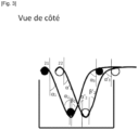
- the invention therefore consists of dividing (or separating) all N of the wicks present at the tank inlet into two groups ( 1st (21) and 2nd (22) groups) ( figure 2 ) of N/2 wicks if N is an even number or for example respectively (N+1)/2 wicks ( 1st group) and (N-1)/2 ( 2nd group) if N is an odd number.
- the wicks belong alternately to the 1st group (21) then to the 2nd group (22).
- the fiber wicks of the 1st group (21) plunge towards the powder in the fluidized bed, after leaving a first locking element denoted emb1 (31) forming an angle ⁇ 1 with the normal to this part of jamming.
- the fiber rovings of the 2nd group plunge towards the powder in the fluidized bed after leaving a first bracing piece denoted emb'1, forming an angle ⁇ ' 1 with the normal to this bracing piece.
- emb'1 securing parts are separated by a distance Demb1-emb'1 at least equal to the thickness of the wick, in particular from 5mm to 100mm, in particular from 10mm to 50mm.
- the fiber rovings of the 1st group of fibers (21) then plunge into the fluidized bed of powder until they come into contact with a second bracing part immersed at least partially in the fluidized bed (totally on the figure 1 And 2 ) noted emb2.
- the angle formed between each strand of fibers and the normal to the bracing element at the point of contact is denoted ⁇ 2 .
- the wicks of the 2nd group of fibers (22) then plunge into the fluidized bed of powder until they come into contact with a second locking part immersed at least partially in the fluidized bed (totally on the figure 1 And 2 ) noted emb'2.
- emb'2 The angle formed between each strand of fibers and the normal to the bracing part at the point of contact is noted ⁇ ' 2 .
- the securing parts emb2 and emb2' are separated by a distance Demb2-emb'2 equal to the distance Demb1- emb'1 and are of the same nature (material, surface, finish etc).
- the rovings of fibers of the 1st group of fibers (21) emerge from the locking piece emb2 with an angle formed between each strand of fibers and the normal to the locking piece denoted ⁇ 2 then the locks impregnated with powder come out of the fluidized bed of powder to come into contact with a last bracing part and denoted emb3.
- the angle formed between each strand of fibers and the normal to the bracing element at the point of contact is noted ⁇ 3 .
- the strands of fibers of the second group of fibers (22) emerge from the emb'2 locking piece with an angle formed between each fiber strand and the normal to the locking piece denoted ⁇ ' 2 then the wicks impregnated with powder come out of the fluidized bed of powder to come into contact with a last bracing part and denoted emb'3.
- the angle formed between each strand of fibers and the normal to the bracing element at the point of contact is denoted ⁇ ' 3 .
- the embarning elements emb3 and emb'3 are separated by a distance Demb3-emb'3 equal to the distance Demb2 -emb2' and therefore Demb1-emb'1 and are of the same nature (material, surface, finish etc).
- the entry and exit angles of the fibers at the entry and exit rolls have a certain impact on the tension generated on the fiber rovings and on the rate of powder carried away by the fiber roving. It is therefore necessary for the system to be symmetrical on these points.
- this residence time is preserved for the two groups of reinforcing fiber rovings by equivalently immersing the two bracing systems emb1' and emb2'; these two bracing systems also having the same contact surface with the fiber rovings on both systems.
Landscapes
- Engineering & Computer Science (AREA)
- Mechanical Engineering (AREA)
- Reinforced Plastic Materials (AREA)
Applications Claiming Priority (2)
| Application Number | Priority Date | Filing Date | Title |
|---|---|---|---|
| FR1871841A FR3088844B1 (fr) | 2018-11-26 | 2018-11-26 | Procede d’impregnation d’un materiau fibreux en lit fluidise interpenetre |
| PCT/FR2019/052799 WO2020109709A2 (fr) | 2018-11-26 | 2019-11-25 | Procede d'impregnation d'un materiau fibreux en lit fluidise interpenetre |
Publications (2)
| Publication Number | Publication Date |
|---|---|
| EP3887115A2 EP3887115A2 (fr) | 2021-10-06 |
| EP3887115B1 true EP3887115B1 (fr) | 2023-11-22 |
Family
ID=66166157
Family Applications (1)
| Application Number | Title | Priority Date | Filing Date |
|---|---|---|---|
| EP19842788.2A Active EP3887115B1 (fr) | 2018-11-26 | 2019-11-25 | Procede d'impregnation d'un materiau fibreux en lit fluidise interpenetre |
Country Status (7)
| Country | Link |
|---|---|
| US (1) | US11364660B2 (https=) |
| EP (1) | EP3887115B1 (https=) |
| JP (1) | JP7598856B2 (https=) |
| KR (1) | KR102877216B1 (https=) |
| CN (1) | CN113165216B (https=) |
| FR (1) | FR3088844B1 (https=) |
| WO (1) | WO2020109709A2 (https=) |
Families Citing this family (3)
| Publication number | Priority date | Publication date | Assignee | Title |
|---|---|---|---|---|
| FR3116468B1 (fr) * | 2020-11-24 | 2023-06-30 | Arkema France | Structure multicouche pour le transport ou le stockage de l’hydrogene |
| BR102022015861A2 (pt) * | 2022-08-10 | 2024-02-15 | Tecplas Industria E Comercio Ltda | Mantas de fibras contínuas pré-impregnadas, multicamadas e multidirecionais com ângulo entre fibras controlável e seu processo de fabricação |
| US20240165853A1 (en) * | 2022-11-17 | 2024-05-23 | Rock Fiber, Inc. | Fiber structural reinforcement with frictional surface coating |
Family Cites Families (11)
| Publication number | Priority date | Publication date | Assignee | Title |
|---|---|---|---|---|
| US5171630A (en) * | 1989-04-17 | 1992-12-15 | Georgia Tech Research Corporation | Flexible multiply towpreg |
| FR2648957B1 (fr) | 1989-06-22 | 1991-11-15 | France Etat Armement | Materiau composite a caracteristiques modulables par preimpregnation d'une fibre continue |
| JPH0740341A (ja) * | 1993-06-29 | 1995-02-10 | Sekisui Chem Co Ltd | 繊維複合シートの製造方法 |
| JP3480990B2 (ja) * | 1994-07-29 | 2003-12-22 | 積水化学工業株式会社 | 繊維複合シートの製造方法 |
| JPH0957862A (ja) * | 1995-08-30 | 1997-03-04 | Sekisui Chem Co Ltd | 繊維複合シートの製造方法 |
| US6190625B1 (en) * | 1997-08-07 | 2001-02-20 | Qualchem, Inc. | Fluidized-bed roasting of molybdenite concentrates |
| FR2858626B1 (fr) | 2003-08-05 | 2005-10-07 | Atofina | Polyamides semi aromatiques souple a faible reprise en humidite |
| MY150895A (en) * | 2007-03-21 | 2014-03-14 | Technip France | Flexible pipe for transporting oil and gas and including a reinforcing layer |
| EP2620465B2 (en) * | 2012-01-27 | 2018-03-28 | Evonik Degussa GmbH | Heat-treatment of water-absorbing polymeric particles in a fluidized bed at a fast heat-up rate |
| FR3017329B1 (fr) | 2014-02-13 | 2016-07-29 | Arkema France | Procede de fabrication d'un materiau fibreux pre-impregne de polymere thermoplastique en lit fluidise |
| FR3061066B1 (fr) | 2016-12-22 | 2020-02-14 | Arkema France | Procede de fabrication d'un materiau fibreux pre-impregne de polymere thermoplastique en lit fluidise |
-
2018
- 2018-11-26 FR FR1871841A patent/FR3088844B1/fr active Active
-
2019
- 2019-11-25 CN CN201980077519.0A patent/CN113165216B/zh active Active
- 2019-11-25 JP JP2021528924A patent/JP7598856B2/ja active Active
- 2019-11-25 US US17/296,651 patent/US11364660B2/en active Active
- 2019-11-25 WO PCT/FR2019/052799 patent/WO2020109709A2/fr not_active Ceased
- 2019-11-25 KR KR1020217012858A patent/KR102877216B1/ko active Active
- 2019-11-25 EP EP19842788.2A patent/EP3887115B1/fr active Active
Also Published As
| Publication number | Publication date |
|---|---|
| JP7598856B2 (ja) | 2024-12-12 |
| CN113165216A (zh) | 2021-07-23 |
| FR3088844B1 (fr) | 2022-03-18 |
| WO2020109709A3 (fr) | 2020-08-06 |
| EP3887115A2 (fr) | 2021-10-06 |
| JP2022509798A (ja) | 2022-01-24 |
| WO2020109709A2 (fr) | 2020-06-04 |
| KR20210093867A (ko) | 2021-07-28 |
| CN113165216B (zh) | 2023-06-20 |
| FR3088844A1 (fr) | 2020-05-29 |
| KR102877216B1 (ko) | 2025-10-27 |
| US11364660B2 (en) | 2022-06-21 |
| US20220016807A1 (en) | 2022-01-20 |
Similar Documents
| Publication | Publication Date | Title |
|---|---|---|
| EP3418323B1 (fr) | Materiau fibreux impregne de polymere thermoplastique | |
| EP3393738B1 (fr) | Procédé de fabrication d'un matériau fibreux pré-imprégné de polymère thermoplastique en lit fluidise | |
| EP3418018B1 (fr) | Procede de fabrication d'un materiau fibreux impregne de polymere thermoplastique | |
| EP3418015B1 (fr) | Procede de fabrication d'un materiau fibreux impregne de polymere thermoplastique | |
| EP3558612B1 (fr) | Procede de fabrication d'un materiau fibreux pre-impregne de polymere thermoplastique sous forme de poudre | |
| EP3558613A1 (fr) | Procédé de fabrication d'un matériau fibreux pré-imprégné de polymère thermoplastique sous forme de poudre sèche | |
| EP3558614A1 (fr) | Procede de fabrication d'un materiau fibreux pre-impregne de polymere thermoplastique par projection | |
| EP3768768B1 (fr) | Materiau fibreux impregne de polymere thermoplastique et d'epaisseur inferieure ou egale a 100 micrometre et son procede de preparation | |
| EP3887115B1 (fr) | Procede d'impregnation d'un materiau fibreux en lit fluidise interpenetre | |
| EP3670130B1 (fr) | Procede de fabrication d'un materiau fibreux impregne de polymere thermoplastique | |
| WO2020126997A1 (fr) | Procede de fabrication d'un materiau fibreux pre-impregne de polymere thermoplastique en lit fluidise | |
| WO2022129781A1 (fr) | Procédé de fabrication d'un matériau fibreux en fibres continues imprégné de polymère thermoplastique |
Legal Events
| Date | Code | Title | Description |
|---|---|---|---|
| STAA | Information on the status of an ep patent application or granted ep patent |
Free format text: STATUS: UNKNOWN |
|
| STAA | Information on the status of an ep patent application or granted ep patent |
Free format text: STATUS: THE INTERNATIONAL PUBLICATION HAS BEEN MADE |
|
| PUAI | Public reference made under article 153(3) epc to a published international application that has entered the european phase |
Free format text: ORIGINAL CODE: 0009012 |
|
| STAA | Information on the status of an ep patent application or granted ep patent |
Free format text: STATUS: REQUEST FOR EXAMINATION WAS MADE |
|
| 17P | Request for examination filed |
Effective date: 20210504 |
|
| AK | Designated contracting states |
Kind code of ref document: A2 Designated state(s): AL AT BE BG CH CY CZ DE DK EE ES FI FR GB GR HR HU IE IS IT LI LT LU LV MC MK MT NL NO PL PT RO RS SE SI SK SM TR |
|
| DAV | Request for validation of the european patent (deleted) | ||
| DAX | Request for extension of the european patent (deleted) | ||
| GRAP | Despatch of communication of intention to grant a patent |
Free format text: ORIGINAL CODE: EPIDOSNIGR1 |
|
| STAA | Information on the status of an ep patent application or granted ep patent |
Free format text: STATUS: GRANT OF PATENT IS INTENDED |
|
| INTG | Intention to grant announced |
Effective date: 20230612 |
|
| GRAS | Grant fee paid |
Free format text: ORIGINAL CODE: EPIDOSNIGR3 |
|
| GRAA | (expected) grant |
Free format text: ORIGINAL CODE: 0009210 |
|
| STAA | Information on the status of an ep patent application or granted ep patent |
Free format text: STATUS: THE PATENT HAS BEEN GRANTED |
|
| AK | Designated contracting states |
Kind code of ref document: B1 Designated state(s): AL AT BE BG CH CY CZ DE DK EE ES FI FR GB GR HR HU IE IS IT LI LT LU LV MC MK MT NL NO PL PT RO RS SE SI SK SM TR |
|
| REG | Reference to a national code |
Ref country code: GB Ref legal event code: FG4D Free format text: NOT ENGLISH |
|
| REG | Reference to a national code |
Ref country code: CH Ref legal event code: EP |
|
| REG | Reference to a national code |
Ref country code: DE Ref legal event code: R096 Ref document number: 602019042030 Country of ref document: DE |
|
| REG | Reference to a national code |
Ref country code: IE Ref legal event code: FG4D Free format text: LANGUAGE OF EP DOCUMENT: FRENCH |
|
| REG | Reference to a national code |
Ref country code: LT Ref legal event code: MG9D |
|
| REG | Reference to a national code |
Ref country code: NL Ref legal event code: MP Effective date: 20231122 |
|
| PG25 | Lapsed in a contracting state [announced via postgrant information from national office to epo] |
Ref country code: GR Free format text: LAPSE BECAUSE OF FAILURE TO SUBMIT A TRANSLATION OF THE DESCRIPTION OR TO PAY THE FEE WITHIN THE PRESCRIBED TIME-LIMIT Effective date: 20240223 |
|
| PG25 | Lapsed in a contracting state [announced via postgrant information from national office to epo] |
Ref country code: IS Free format text: LAPSE BECAUSE OF FAILURE TO SUBMIT A TRANSLATION OF THE DESCRIPTION OR TO PAY THE FEE WITHIN THE PRESCRIBED TIME-LIMIT Effective date: 20240322 |
|
| PG25 | Lapsed in a contracting state [announced via postgrant information from national office to epo] |
Ref country code: LT Free format text: LAPSE BECAUSE OF FAILURE TO SUBMIT A TRANSLATION OF THE DESCRIPTION OR TO PAY THE FEE WITHIN THE PRESCRIBED TIME-LIMIT Effective date: 20231122 |
|
| REG | Reference to a national code |
Ref country code: AT Ref legal event code: MK05 Ref document number: 1633438 Country of ref document: AT Kind code of ref document: T Effective date: 20231122 |
|
| PG25 | Lapsed in a contracting state [announced via postgrant information from national office to epo] |
Ref country code: NL Free format text: LAPSE BECAUSE OF FAILURE TO SUBMIT A TRANSLATION OF THE DESCRIPTION OR TO PAY THE FEE WITHIN THE PRESCRIBED TIME-LIMIT Effective date: 20231122 |
|
| PG25 | Lapsed in a contracting state [announced via postgrant information from national office to epo] |
Ref country code: AT Free format text: LAPSE BECAUSE OF FAILURE TO SUBMIT A TRANSLATION OF THE DESCRIPTION OR TO PAY THE FEE WITHIN THE PRESCRIBED TIME-LIMIT Effective date: 20231122 |
|
| PG25 | Lapsed in a contracting state [announced via postgrant information from national office to epo] |
Ref country code: ES Free format text: LAPSE BECAUSE OF FAILURE TO SUBMIT A TRANSLATION OF THE DESCRIPTION OR TO PAY THE FEE WITHIN THE PRESCRIBED TIME-LIMIT Effective date: 20231122 |
|
| PG25 | Lapsed in a contracting state [announced via postgrant information from national office to epo] |
Ref country code: NL Free format text: LAPSE BECAUSE OF FAILURE TO SUBMIT A TRANSLATION OF THE DESCRIPTION OR TO PAY THE FEE WITHIN THE PRESCRIBED TIME-LIMIT Effective date: 20231122 Ref country code: LT Free format text: LAPSE BECAUSE OF FAILURE TO SUBMIT A TRANSLATION OF THE DESCRIPTION OR TO PAY THE FEE WITHIN THE PRESCRIBED TIME-LIMIT Effective date: 20231122 Ref country code: IS Free format text: LAPSE BECAUSE OF FAILURE TO SUBMIT A TRANSLATION OF THE DESCRIPTION OR TO PAY THE FEE WITHIN THE PRESCRIBED TIME-LIMIT Effective date: 20240322 Ref country code: GR Free format text: LAPSE BECAUSE OF FAILURE TO SUBMIT A TRANSLATION OF THE DESCRIPTION OR TO PAY THE FEE WITHIN THE PRESCRIBED TIME-LIMIT Effective date: 20240223 Ref country code: ES Free format text: LAPSE BECAUSE OF FAILURE TO SUBMIT A TRANSLATION OF THE DESCRIPTION OR TO PAY THE FEE WITHIN THE PRESCRIBED TIME-LIMIT Effective date: 20231122 Ref country code: BG Free format text: LAPSE BECAUSE OF FAILURE TO SUBMIT A TRANSLATION OF THE DESCRIPTION OR TO PAY THE FEE WITHIN THE PRESCRIBED TIME-LIMIT Effective date: 20240222 Ref country code: AT Free format text: LAPSE BECAUSE OF FAILURE TO SUBMIT A TRANSLATION OF THE DESCRIPTION OR TO PAY THE FEE WITHIN THE PRESCRIBED TIME-LIMIT Effective date: 20231122 Ref country code: PT Free format text: LAPSE BECAUSE OF FAILURE TO SUBMIT A TRANSLATION OF THE DESCRIPTION OR TO PAY THE FEE WITHIN THE PRESCRIBED TIME-LIMIT Effective date: 20240322 |
|
| PG25 | Lapsed in a contracting state [announced via postgrant information from national office to epo] |
Ref country code: SE Free format text: LAPSE BECAUSE OF FAILURE TO SUBMIT A TRANSLATION OF THE DESCRIPTION OR TO PAY THE FEE WITHIN THE PRESCRIBED TIME-LIMIT Effective date: 20231122 Ref country code: RS Free format text: LAPSE BECAUSE OF FAILURE TO SUBMIT A TRANSLATION OF THE DESCRIPTION OR TO PAY THE FEE WITHIN THE PRESCRIBED TIME-LIMIT Effective date: 20231122 Ref country code: PL Free format text: LAPSE BECAUSE OF FAILURE TO SUBMIT A TRANSLATION OF THE DESCRIPTION OR TO PAY THE FEE WITHIN THE PRESCRIBED TIME-LIMIT Effective date: 20231122 Ref country code: NO Free format text: LAPSE BECAUSE OF FAILURE TO SUBMIT A TRANSLATION OF THE DESCRIPTION OR TO PAY THE FEE WITHIN THE PRESCRIBED TIME-LIMIT Effective date: 20240222 Ref country code: LV Free format text: LAPSE BECAUSE OF FAILURE TO SUBMIT A TRANSLATION OF THE DESCRIPTION OR TO PAY THE FEE WITHIN THE PRESCRIBED TIME-LIMIT Effective date: 20231122 Ref country code: HR Free format text: LAPSE BECAUSE OF FAILURE TO SUBMIT A TRANSLATION OF THE DESCRIPTION OR TO PAY THE FEE WITHIN THE PRESCRIBED TIME-LIMIT Effective date: 20231122 |
|
| REG | Reference to a national code |
Ref country code: CH Ref legal event code: PL |
|
| PG25 | Lapsed in a contracting state [announced via postgrant information from national office to epo] |
Ref country code: DK Free format text: LAPSE BECAUSE OF FAILURE TO SUBMIT A TRANSLATION OF THE DESCRIPTION OR TO PAY THE FEE WITHIN THE PRESCRIBED TIME-LIMIT Effective date: 20231122 |
|
| PG25 | Lapsed in a contracting state [announced via postgrant information from national office to epo] |
Ref country code: LU Free format text: LAPSE BECAUSE OF NON-PAYMENT OF DUE FEES Effective date: 20231125 |
|
| PG25 | Lapsed in a contracting state [announced via postgrant information from national office to epo] |
Ref country code: CH Free format text: LAPSE BECAUSE OF NON-PAYMENT OF DUE FEES Effective date: 20231130 |
|
| PG25 | Lapsed in a contracting state [announced via postgrant information from national office to epo] |
Ref country code: CZ Free format text: LAPSE BECAUSE OF FAILURE TO SUBMIT A TRANSLATION OF THE DESCRIPTION OR TO PAY THE FEE WITHIN THE PRESCRIBED TIME-LIMIT Effective date: 20231122 |
|
| PG25 | Lapsed in a contracting state [announced via postgrant information from national office to epo] |
Ref country code: SK Free format text: LAPSE BECAUSE OF FAILURE TO SUBMIT A TRANSLATION OF THE DESCRIPTION OR TO PAY THE FEE WITHIN THE PRESCRIBED TIME-LIMIT Effective date: 20231122 |
|
| PG25 | Lapsed in a contracting state [announced via postgrant information from national office to epo] |
Ref country code: SM Free format text: LAPSE BECAUSE OF FAILURE TO SUBMIT A TRANSLATION OF THE DESCRIPTION OR TO PAY THE FEE WITHIN THE PRESCRIBED TIME-LIMIT Effective date: 20231122 Ref country code: SK Free format text: LAPSE BECAUSE OF FAILURE TO SUBMIT A TRANSLATION OF THE DESCRIPTION OR TO PAY THE FEE WITHIN THE PRESCRIBED TIME-LIMIT Effective date: 20231122 Ref country code: RO Free format text: LAPSE BECAUSE OF FAILURE TO SUBMIT A TRANSLATION OF THE DESCRIPTION OR TO PAY THE FEE WITHIN THE PRESCRIBED TIME-LIMIT Effective date: 20231122 Ref country code: LU Free format text: LAPSE BECAUSE OF NON-PAYMENT OF DUE FEES Effective date: 20231125 Ref country code: IT Free format text: LAPSE BECAUSE OF FAILURE TO SUBMIT A TRANSLATION OF THE DESCRIPTION OR TO PAY THE FEE WITHIN THE PRESCRIBED TIME-LIMIT Effective date: 20231122 Ref country code: EE Free format text: LAPSE BECAUSE OF FAILURE TO SUBMIT A TRANSLATION OF THE DESCRIPTION OR TO PAY THE FEE WITHIN THE PRESCRIBED TIME-LIMIT Effective date: 20231122 Ref country code: DK Free format text: LAPSE BECAUSE OF FAILURE TO SUBMIT A TRANSLATION OF THE DESCRIPTION OR TO PAY THE FEE WITHIN THE PRESCRIBED TIME-LIMIT Effective date: 20231122 Ref country code: CZ Free format text: LAPSE BECAUSE OF FAILURE TO SUBMIT A TRANSLATION OF THE DESCRIPTION OR TO PAY THE FEE WITHIN THE PRESCRIBED TIME-LIMIT Effective date: 20231122 Ref country code: CH Free format text: LAPSE BECAUSE OF NON-PAYMENT OF DUE FEES Effective date: 20231130 |
|
| REG | Reference to a national code |
Ref country code: BE Ref legal event code: MM Effective date: 20231130 |
|
| REG | Reference to a national code |
Ref country code: DE Ref legal event code: R097 Ref document number: 602019042030 Country of ref document: DE |
|
| PG25 | Lapsed in a contracting state [announced via postgrant information from national office to epo] |
Ref country code: MC Free format text: LAPSE BECAUSE OF FAILURE TO SUBMIT A TRANSLATION OF THE DESCRIPTION OR TO PAY THE FEE WITHIN THE PRESCRIBED TIME-LIMIT Effective date: 20231122 |
|
| PG25 | Lapsed in a contracting state [announced via postgrant information from national office to epo] |
Ref country code: MC Free format text: LAPSE BECAUSE OF FAILURE TO SUBMIT A TRANSLATION OF THE DESCRIPTION OR TO PAY THE FEE WITHIN THE PRESCRIBED TIME-LIMIT Effective date: 20231122 |
|
| REG | Reference to a national code |
Ref country code: IE Ref legal event code: MM4A |
|
| PLBE | No opposition filed within time limit |
Free format text: ORIGINAL CODE: 0009261 |
|
| STAA | Information on the status of an ep patent application or granted ep patent |
Free format text: STATUS: NO OPPOSITION FILED WITHIN TIME LIMIT |
|
| PG25 | Lapsed in a contracting state [announced via postgrant information from national office to epo] |
Ref country code: IE Free format text: LAPSE BECAUSE OF NON-PAYMENT OF DUE FEES Effective date: 20231125 |
|
| PG25 | Lapsed in a contracting state [announced via postgrant information from national office to epo] |
Ref country code: BE Free format text: LAPSE BECAUSE OF NON-PAYMENT OF DUE FEES Effective date: 20231130 |
|
| PG25 | Lapsed in a contracting state [announced via postgrant information from national office to epo] |
Ref country code: SI Free format text: LAPSE BECAUSE OF FAILURE TO SUBMIT A TRANSLATION OF THE DESCRIPTION OR TO PAY THE FEE WITHIN THE PRESCRIBED TIME-LIMIT Effective date: 20231122 |
|
| 26N | No opposition filed |
Effective date: 20240823 |
|
| PG25 | Lapsed in a contracting state [announced via postgrant information from national office to epo] |
Ref country code: SI Free format text: LAPSE BECAUSE OF FAILURE TO SUBMIT A TRANSLATION OF THE DESCRIPTION OR TO PAY THE FEE WITHIN THE PRESCRIBED TIME-LIMIT Effective date: 20231122 Ref country code: IE Free format text: LAPSE BECAUSE OF NON-PAYMENT OF DUE FEES Effective date: 20231125 Ref country code: BE Free format text: LAPSE BECAUSE OF NON-PAYMENT OF DUE FEES Effective date: 20231130 |
|
| PG25 | Lapsed in a contracting state [announced via postgrant information from national office to epo] |
Ref country code: FI Free format text: LAPSE BECAUSE OF FAILURE TO SUBMIT A TRANSLATION OF THE DESCRIPTION OR TO PAY THE FEE WITHIN THE PRESCRIBED TIME-LIMIT Effective date: 20231122 |
|
| PG25 | Lapsed in a contracting state [announced via postgrant information from national office to epo] |
Ref country code: CY Free format text: LAPSE BECAUSE OF FAILURE TO SUBMIT A TRANSLATION OF THE DESCRIPTION OR TO PAY THE FEE WITHIN THE PRESCRIBED TIME-LIMIT; INVALID AB INITIO Effective date: 20191125 |
|
| PG25 | Lapsed in a contracting state [announced via postgrant information from national office to epo] |
Ref country code: HU Free format text: LAPSE BECAUSE OF FAILURE TO SUBMIT A TRANSLATION OF THE DESCRIPTION OR TO PAY THE FEE WITHIN THE PRESCRIBED TIME-LIMIT; INVALID AB INITIO Effective date: 20191125 |
|
| PGFP | Annual fee paid to national office [announced via postgrant information from national office to epo] |
Ref country code: FR Payment date: 20250930 Year of fee payment: 7 |
|
| PG25 | Lapsed in a contracting state [announced via postgrant information from national office to epo] |
Ref country code: TR Free format text: LAPSE BECAUSE OF FAILURE TO SUBMIT A TRANSLATION OF THE DESCRIPTION OR TO PAY THE FEE WITHIN THE PRESCRIBED TIME-LIMIT Effective date: 20231122 |
|
| REG | Reference to a national code |
Ref country code: DE Ref legal event code: R081 Ref document number: 602019042030 Country of ref document: DE Owner name: ARKEMA FRANCE, FR Free format text: FORMER OWNER: ARKEMA FRANCE, COLOMBES, FR |
|
| PGFP | Annual fee paid to national office [announced via postgrant information from national office to epo] |
Ref country code: DE Payment date: 20250930 Year of fee payment: 7 |
|
| PGFP | Annual fee paid to national office [announced via postgrant information from national office to epo] |
Ref country code: GB Payment date: 20251001 Year of fee payment: 7 |