EP3886409B1 - Schutzgehäuseanordnung für eine tragbare vorrichtung - Google Patents
Schutzgehäuseanordnung für eine tragbare vorrichtung Download PDFInfo
- Publication number
- EP3886409B1 EP3886409B1 EP20186014.5A EP20186014A EP3886409B1 EP 3886409 B1 EP3886409 B1 EP 3886409B1 EP 20186014 A EP20186014 A EP 20186014A EP 3886409 B1 EP3886409 B1 EP 3886409B1
- Authority
- EP
- European Patent Office
- Prior art keywords
- peripheral surface
- frame
- surface part
- inner peripheral
- outer peripheral
- Prior art date
- Legal status (The legal status is an assumption and is not a legal conclusion. Google has not performed a legal analysis and makes no representation as to the accuracy of the status listed.)
- Active
Links
Images


Classifications
-
- H—ELECTRICITY
- H04—ELECTRIC COMMUNICATION TECHNIQUE
- H04M—TELEPHONIC COMMUNICATION
- H04M1/00—Substation equipment, e.g. for use by subscribers
- H04M1/02—Constructional features of telephone sets
- H04M1/18—Telephone sets specially adapted for use in ships, mines, or other places exposed to adverse environment
- H04M1/185—Improving the shock resistance of the housing, e.g. by increasing the rigidity
-
- G—PHYSICS
- G03—PHOTOGRAPHY; CINEMATOGRAPHY; ANALOGOUS TECHNIQUES USING WAVES OTHER THAN OPTICAL WAVES; ELECTROGRAPHY; HOLOGRAPHY
- G03B—APPARATUS OR ARRANGEMENTS FOR TAKING PHOTOGRAPHS OR FOR PROJECTING OR VIEWING THEM; APPARATUS OR ARRANGEMENTS EMPLOYING ANALOGOUS TECHNIQUES USING WAVES OTHER THAN OPTICAL WAVES; ACCESSORIES THEREFOR
- G03B11/00—Filters or other obturators specially adapted for photographic purposes
- G03B11/04—Hoods or caps for eliminating unwanted light from lenses, viewfinders or focusing aids
- G03B11/043—Protective lens closures or lens caps built into cameras
-
- G—PHYSICS
- G03—PHOTOGRAPHY; CINEMATOGRAPHY; ANALOGOUS TECHNIQUES USING WAVES OTHER THAN OPTICAL WAVES; ELECTROGRAPHY; HOLOGRAPHY
- G03B—APPARATUS OR ARRANGEMENTS FOR TAKING PHOTOGRAPHS OR FOR PROJECTING OR VIEWING THEM; APPARATUS OR ARRANGEMENTS EMPLOYING ANALOGOUS TECHNIQUES USING WAVES OTHER THAN OPTICAL WAVES; ACCESSORIES THEREFOR
- G03B11/00—Filters or other obturators specially adapted for photographic purposes
- G03B11/04—Hoods or caps for eliminating unwanted light from lenses, viewfinders or focusing aids
- G03B11/045—Lens hoods or shields
-
- G—PHYSICS
- G06—COMPUTING OR CALCULATING; COUNTING
- G06F—ELECTRIC DIGITAL DATA PROCESSING
- G06F1/00—Details not covered by groups G06F3/00 - G06F13/00 and G06F21/00
- G06F1/16—Constructional details or arrangements
- G06F1/1613—Constructional details or arrangements for portable computers
- G06F1/1626—Constructional details or arrangements for portable computers with a single-body enclosure integrating a flat display, e.g. Personal Digital Assistants [PDAs]
-
- G—PHYSICS
- G06—COMPUTING OR CALCULATING; COUNTING
- G06F—ELECTRIC DIGITAL DATA PROCESSING
- G06F1/00—Details not covered by groups G06F3/00 - G06F13/00 and G06F21/00
- G06F1/16—Constructional details or arrangements
- G06F1/1613—Constructional details or arrangements for portable computers
- G06F1/1628—Enclosures for carrying portable computers with peripheral devices, e.g. cases for a laptop and a printer
-
- G—PHYSICS
- G06—COMPUTING OR CALCULATING; COUNTING
- G06F—ELECTRIC DIGITAL DATA PROCESSING
- G06F1/00—Details not covered by groups G06F3/00 - G06F13/00 and G06F21/00
- G06F1/16—Constructional details or arrangements
- G06F1/1613—Constructional details or arrangements for portable computers
- G06F1/1633—Constructional details or arrangements of portable computers not specific to the type of enclosures covered by groups G06F1/1615 - G06F1/1626
- G06F1/1656—Details related to functional adaptations of the enclosure, e.g. to provide protection against EMI, shock, water, or to host detachable peripherals like a mouse or removable expansions units like PCMCIA cards, or to provide access to internal components for maintenance or to removable storage supports like CDs or DVDs, or to mechanically mount accessories
-
- G—PHYSICS
- G06—COMPUTING OR CALCULATING; COUNTING
- G06F—ELECTRIC DIGITAL DATA PROCESSING
- G06F1/00—Details not covered by groups G06F3/00 - G06F13/00 and G06F21/00
- G06F1/16—Constructional details or arrangements
- G06F1/1613—Constructional details or arrangements for portable computers
- G06F1/1633—Constructional details or arrangements of portable computers not specific to the type of enclosures covered by groups G06F1/1615 - G06F1/1626
- G06F1/1684—Constructional details or arrangements related to integrated I/O peripherals not covered by groups G06F1/1635 - G06F1/1675
- G06F1/1686—Constructional details or arrangements related to integrated I/O peripherals not covered by groups G06F1/1635 - G06F1/1675 the I/O peripheral being an integrated camera
-
- H—ELECTRICITY
- H04—ELECTRIC COMMUNICATION TECHNIQUE
- H04B—TRANSMISSION
- H04B1/00—Details of transmission systems, not covered by a single one of groups H04B3/00 - H04B13/00; Details of transmission systems not characterised by the medium used for transmission
- H04B1/38—Transceivers, i.e. devices in which transmitter and receiver form a structural unit and in which at least one part is used for functions of transmitting and receiving
- H04B1/3827—Portable transceivers
- H04B1/3888—Arrangements for carrying or protecting transceivers
-
- H—ELECTRICITY
- H04—ELECTRIC COMMUNICATION TECHNIQUE
- H04M—TELEPHONIC COMMUNICATION
- H04M1/00—Substation equipment, e.g. for use by subscribers
- H04M1/02—Constructional features of telephone sets
- H04M1/0202—Portable telephone sets, e.g. cordless phones, mobile phones or bar type handsets
- H04M1/026—Details of the structure or mounting of specific components
- H04M1/0264—Details of the structure or mounting of specific components for a camera module assembly
Definitions
- the present invention relates to a protection case assembly, and more particularly to a protection case assembly for a handheld device.
- a structure corresponding to the lens module of a handheld device is mostly a basic opening. Such structure provides a relatively low level of protection for the lens module, and at the same time does not offer other additional effects. Therefore, there is significant room for improvement of the structure of a current protection accessory for a handheld device.
- the protection case assembly includes a main case and a frame.
- the main case has an accommodating space configured to accommodate the handheld device, and an opening disposed correspondingly to a lens module of the handheld device.
- the frame is detachably disposed in the opening, and includes a groove set configured to receive the main case in the opening.
- the opening has an inner peripheral surface.
- the frame has an outer peripheral surface corresponding to the inner peripheral surface.
- the groove set includes at least one groove formed on the outer peripheral surface and configured to receive the main case in the opening.
- the frame further includes a pad portion, and the pad portion protrudes toward the accommodating space when the frame is disposed in the opening.
- the pad portion is provided at the frame correspondingly to an encirclement of the frame.
- the material hardness of the groove set is more than the material hardness of the pad portion.
- between the surface of the pad portion facing the accommodating space and the surface of the backplate facing the accommodating space is a height difference.
- the height difference is between 0.1 mm and 1 mm.
- the present invention further provides a protection case assembly for a handheld device.
- the protection case assembly includes a main case and a frame.
- the main case has an accommodating space configured to accommodate the handheld device, and a backplate provided with an opening corresponding to a lens module of the handheld device.
- the frame is detachably disposed in the opening, and includes a first frame part corresponding to a first inner peripheral surface of the opening, a second frame part opposite to the first frame part and corresponding to a second inner peripheral surface of the opening, a third frame part corresponding to a third inner peripheral surface of the opening, and a fourth frame part opposite to the third frame part and corresponding to a fourth inner peripheral surface of the opening.
- the first frame part On a first cross section of the opening, the first frame part forms a first groove toward the first inner peripheral surface, and the first inner peripheral surface is received between two protrusions of the first groove.
- the third frame part On a second cross section of the opening, the third frame part forms a first L shape, and a protrusion of the first L shape is abutted against the backplate from the accommodating space.
- the first frame part is adjacent to the third frame part and the fourth frame part.
- the second frame part is adjacent to the third frame part and the fourth frame part.
- the second frame part forms a second groove toward the second inner peripheral surface, and the second inner peripheral surface is received between two protrusions of the second groove.
- the fourth frame part forms a second L shape, and a protrusion of the second L shape is abutted against the backplate from the accommodating space.
- the opening forms a protrusion on the first inner peripheral surface.
- the protrusion of the first inner peripheral surface is received between the two protrusions of the first groove.
- the thickness of the protrusion of the first inner peripheral surface is less than the thickness of the backplate.
- the first cross section crosses the second cross section cross, and the first cross section and the second cross section individually cross an extension surface of the backplate.
- a first feature formed above or on a second feature in the description may include an embodiment in which the first feature and the second feature are formed in a direct contact manner, and may include an embodiment in which an additional feature is formed between the first feature and the second feature such that the first feature and the second feature may not be in direct contact.
- drawing symbols and/or characters may be repeated in the embodiments. Such repetition is for the purpose of simplification and clarity, and does not indicate relationships of the embodiments and/or configurations discussed.
- Value ranges and parameters for describing general ranges of the present invention are approximate values, and values given in specific embodiments are reported as accurately as possible. However, some values may contain errors caused by discovered standard errors in individual test and measurement values. Further, the term “approximately” usually means that a given value or range is within an error of ⁇ 10%, ⁇ 5%, ⁇ 1% or ⁇ 0.5%. In substitution, a person skilled in the art would consider that the term “approximately” means an acceptable standard error of an average value.
- substantially coplanar may refer to two surfaces that are within a few micrometers ( ⁇ m) along the same plane (such as within 10 ⁇ m, 5 ⁇ m, 1 ⁇ m, or 0.5 ⁇ m along the same plane). Where values or characteristics are said to be “substantially” the same, the term may mean that the values are within ⁇ 10%, ⁇ 5%, ⁇ 1% or ⁇ 0.5% of the average of the values.
- a protection case assembly disclosed by the present invention is configured to accommodate a handheld device.
- the protection case assembly includes a main case and a frame detachably disposed in an opening of the main case.
- the frame may serve as a liner, and conformally encircles an inner peripheral surface of the opening.
- the frame and the main case at least simultaneously have two different receiving structures.
- the two different receiving structures may include a structure in which the frame and the main case are abutted by a single side, or at least may include a structure in which the frame is designed with two walls that clamp the main case. It is an object of the present invention to provide at least two different receiving structures for enhancing convenience for installing/removing the frame for a user.
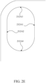
- FIG. 1A shows a three-dimensional diagram of a protection case assembly 1 according to some embodiments of the present invention.
- FIG. 1B shows an exploded diagram of the protection case assembly 1 according to some embodiments of the present invention.
- the protection case assembly 1 includes a main case 11 and a frame 13.
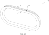
- FIG. 1C shows a three-dimensional diagram of the frame 13 according to some embodiments of the present invention.
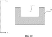
- FIG. 1D shows a section diagram of the frame 13 along a section line A-A' in FIG. 1C .
- FIG. 1E and FIG. 1F are schematic diagrams of the protection case assembly 1 in use according to some embodiments of the present invention.
- the main case 11 has an accommodating space 110 configured to accommodate a handheld device 9.
- the handheld device 9 is detachably disposed in the accommodating space 110 of the main case 11.
- the main case 11 has an opening 112, and the frame 13 is detachably disposed in the opening 112.
- the frame 13 has a groove set 131 configured to fittingly receive the main case 11 in the opening 112.
- the shape of the space defined by the hollow part of the frame 13 matches the shape of the lens module 91 protruding from the back surface 90.
- the space defined by the hollow part of the frame 13 may be coupled to the lens module 91 and provides the lens module 91 with protection, at the same time enhancing the overall esthetic values of the protection case assembly 1.
- FIG. 2A shows a three-dimensional diagram of a protection case assembly 2 according to some embodiments of the present invention.
- FIG. 2 shows an exploded diagram of the protection case assembly 2 according to some embodiments of the present invention.
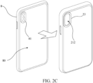
- FIG. 2C shows a schematic diagram of the protection case assembly 2 in use according to some embodiments of the present invention.
- the protection case assembly 2 includes a main case 21 and a frame 23.
- the main case 21 has an accommodating space 210 and a backplate 211.
- the accommodating space 210 of the main case 21 is defined by a rim 25 and the backplate 211 of the main case 21, and is configured to accommodate a handheld device 8.
- the handheld device 8 is detachably disposed in the accommodating space 210 of the main case 21.
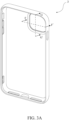
- the handheld device 8 includes a lens module 81 provided on a back surface 80 of the handheld device 8.
- the main case 21 is provided with an opening 212 on the backplate 211 on a position corresponding to the lens module 81 so as to expose the lens module 81.
- the frame 23 is detachably disposed in the opening 212.
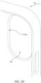
- FIG. 2D shows an enlarged partial diagram of the main case 21 according to some embodiments of the present invention.
- FIG. 2E shows a front view of the main case 21 in a direction D1 in FIG. 2D of the present invention.
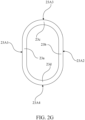
- FIG. 2F shows a three-dimensional diagram of the frame 23 according to some embodiments of the present invention.
- FIG. 2G shows a front view of the frame 23 in a direction D2 in FIG. 2F of the present invention.
- the opening 212 has an inner peripheral surface 212A encircling the opening 212.
- the inner peripheral surface 212A defines the hole of the opening 212, and is connected to inner and outer surfaces of the backplate 211.
- the frame 23 has an outer peripheral surface 23A encircling the frame 23.
- a groove set 231 is formed on the outer peripheral surface 23A, and is configured to fittingly receive the main case 21 in the opening 212.
- the inner peripheral surface 212A of the opening 212 may be divided into a first inner peripheral part 212A1, a second inner peripheral surface part 212A2, a third inner peripheral surface part 212A3 and a fourth inner peripheral surface part 212A4.
- the first inner peripheral surface part 212A1 is opposite to the second inner peripheral surface part 212A2
- the third inner peripheral surface part 212A3 is opposite to the fourth inner peripheral surface part 212A4.
- the third inner peripheral surface part 212A3 is adjacent to the first inner peripheral surface part 212A1 and the second inner peripheral surface part 212A2
- the fourth inner peripheral surface part 212A4 is adjacent to the first inner peripheral surface part 212A1 and the second inner peripheral surface part 212A2.
- the inner peripheral surface parts 212A1 to 212A4 are connected to form the inner peripheral surface 212A of the opening 212.
- the outer peripheral surface 23A of the frame 23 may be divided into a first outer peripheral surface part 23A1, a second outer peripheral surface part 23A2, a third outer peripheral surface part 23A3 and a fourth outer peripheral surface part 23A4.
- the third outer peripheral surface part 23A3 is adjacent to the first outer peripheral surface part 23A1 and the second outer peripheral surface part 23A2
- the fourth outer peripheral surface part 23A4 is adjacent to the first outer peripheral surface part 23A1 and the second outer peripheral surface part 23A2.
- the outer peripheral surface parts 21A1 to 23A4 are connected to form the outer peripheral surface 23A of the frame 23.
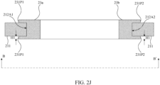
- FIG. 2J shows a section diagram of the protection case assembly 2 along the section line B-B' in FIG. 2A .
- FIG 2K shows a section diagram of the protection case assembly 2 along the section line C-C' in FIG. 2A .
- the first inner peripheral surface part 212A1 is fittingly received between the two first protrusions 231P1 of the first groove 231G1; (2) the second inner peripheral surface part 212A2 is fittingly received between the two second protrusions 231P2 of the second groove 231G2; (3) the third inner peripheral surface part 212A3 is adjacent to the first flat area 23F1 of the third outer peripheral surface part 23A3, and the protrusion 23P1 is abutted against the surface of the backplate 211 facing the accommodating space 210; and (4) the fourth inner peripheral surface part 212A4 is adjacent to the second flat area 23F2 of the fourth outer peripheral surface part 23A4, and the protrusion 23P2 is abutted against the surface of the backplate 211 facing the accommodating space 210.
- the first frame part 23a forms the first 231G1 toward the first inner peripheral surface part 212A1, and the first inner peripheral surface part 212A1 is fittingly received between the two first protrusions 231P1 of the first groove 231G1;
- the second frame part 23b forms the second groove 231G2 toward the second inner peripheral surface part 212A2, and the second inner peripheral surface part 212A2 is fittingly received between the two second protrusions 231P2 of the second groove 231G2;
- the third frame part 23c substantially forms an L shape on the cross section, and the protrusion 23P1 of the L shape is abutted against the surface of the backplate 211 facing the accommodating space 210; and
- the fourth frame part 23d substantially forms an L shape on the cross section, and the protrusion 23P2 of the L shape is abutted against the surface of the back
- the first protrusions 231P1 located in the accommodating space 210, the second protrusions 231P2 located in the accommodating space 210, the protrusion 23P1 of the third outer peripheral surface part 23A3 and the protrusion 23P2 of the fourth outer peripheral surface part 23A4 are connected and appear as an encirclement.
- a height difference H1 is a height difference between the surface of the connected protrusions facing the accommodating space 210 and the surface of the backplate 211 facing the accommodating space 210.
- the frame 23 may pad the backplate 211 away from the back surface 80 of the handheld device 8, so as to prevent the backplate 211 from directly contacting the back surface 80 of the handheld device 8, thereby further avoiding water ripples generated when the backplate 211 contacts the back surface 80 of the handheld device 8.
- FIG. 3A shows a three-dimensional diagram of a protection case assembly 3 according to some embodiments of the present invention.
- FIG. 3B shows an exploded diagram of the protection case assembly 3 according to some embodiments of the present invention.
- FIG. 3C shows a schematic diagram of the protection case assembly 3 in use according to some embodiments of the present invention.
- the protection case assembly 3 includes a main case 31 and a frame 33.
- the main case 31 has an accommodating space 310 and a backplate 311.
- the accommodating space 310 of the main case 31 is defined by a frame 35 and the backplate 311 of the main case 31, and is configured to accommodate the handheld device 7.
- the handheld device 7 is detachably disposed in the accommodating space 310 of the main case 31.
- the handheld device 7 includes a lens module 71 provided on a back surface 70 of the handheld device 7.
- the main case 31 is provided with an opening 312 on a position corresponding to the lens module 71 so as to expose the lens module 71.
- the frame 33 is detachably disposed in the opening 312.
- FIG. 3D shows an enlarged partial diagram of the main case 31 according to some embodiments of the present invention.
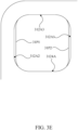
- FIG. 3E shows a front view of the main case 31 in a direction D3 in FIG. 3D of the present invention.
- FIG. 3F shows a three-dimensional diagram of the frame 33 according to some embodiments of the present invention.
- FIG. 3G shows a front view of the frame 33 in a direction D4 in FIG. 3F of the present invention.
- the opening 312 has an inner peripheral surface 312A encircling the opening 312.
- the inner peripheral surface 312A defines the hole of the opening 312, and is connected to an inner surface and an outer surface of the backplate 311.
- the frame 33 has an outer peripheral surface 33A encircling the frame 33.
- a groove set 331 is formed on the outer peripheral surface 33A, and is configured to fittingly receive the main case 31 in the opening 312.
- the inner peripheral surface 312A of the opening 312 may be divided into a first inner peripheral surface part 312A1, a second inner peripheral surface part 312A2, a third inner peripheral surface part 312A3 and a fourth inner peripheral surface part 312A4.
- the first inner peripheral surface part 312A1 is opposite to the second inner peripheral surface part 312A2
- the third inner peripheral surface part 312A3 is opposite to the fourth inner peripheral surface part 312A4.
- the third inner peripheral surface part 312A3 is adjacent to the first inner peripheral surface part 312A1 and the second inner peripheral surface part 312A2 and the fourth inner peripheral surface part 312A4 is adjacent to the first inner peripheral surface part 312A1 and the second inner peripheral surface part 312A2.
- the inner peripheral surface parts 312A1 to 312A4 are connected to form the inner peripheral surface 312A of the opening 312.
- the outer peripheral surface 33A of the frame 33 may be divided into a first outer peripheral surface part 33A1, a second outer peripheral surface part 33A2, a third outer peripheral surface part 33A3 and a fourth outer peripheral surface part 33A4.
- the third outer peripheral surface part 33A3 is adjacent to the first outer peripheral surface part 33A1 and the second outer peripheral surface part 33A2
- the fourth outer peripheral surface part 33A4 is adjacent to the first outer peripheral surface part 33A1 and the second outer peripheral surface part 33A2.
- the outer peripheral surface parts 33A1 to 33A4 are connected to form the outer peripheral surface 33A of the frame 33.
- the frame 33 may be distinguished into a first frame part 33a, a second frame part 33b, a third frame part 33c and a fourth frame part 33d based on the first outer peripheral surface part 33A1, the second outer peripheral surface part 33A2, the third outer peripheral surface part 33A3 and the fourth outer peripheral surface part 33A4.
- the first frame part 33a is adjacent to the third 33c and the fourth frame part 33d
- the second frame part 33b is adjacent to the third frame part 33c and the fourth frame part 33d.
- the frame parts 33a to 33d are connected to form the frame 33.
- the first inner peripheral surface part 312A1 forms a protrusion 31P1
- the second inner peripheral surface part 312A2 form a protrusion 31P2.
- the protrusions 31P1 and 31P2 are disposed opposite to each other in the opening 312, and the thicknesses of the protrusions 31P1 and 31P2 are less than the thickness of the backplate 311.
- the first outer peripheral surface part 33A1 and the first frame part 33a correspond to the first inner peripheral surface part 312A1 and the protrusion 31P1
- the second outer peripheral surface part 33A2 and the second frame part 33b correspond to the second inner peripheral surface part 312A2 and the protrusion 31P2
- the third outer peripheral surface part 33A3 and the third frame part 33c correspond to the third inner peripheral surface part 312A3
- the fourth outer peripheral surface part 33A4 and the fourth frame part 33d correspond to the fourth inner peripheral surface part 312A4.
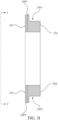
- FIG. 3H shows a section diagram of the frame 33 along the section line H-H' in FIG. 3F .
- FIG. 3I shows a section diagram of the frame 33 along the section line I-I' in FIG. 3F .
- the groove set 331 of the frame 33 includes a first groove 331G1 and a second groove 331G2, the first groove 331G1 is formed on the first outer peripheral surface part 33A1 and includes two first protrusions 331P1, and the second groove 331G2 is formed on the second outer peripheral surface part 33A2 and includes two second protrusions 331P2.
- the two first protrusions 331P1 protrude on two ends of the first peripheral surface part 33A1 along the frame 33, and thus the two first protrusions 331P1 and the first outer peripheral surface part 33A1 jointly form the first groove 331G1.
- the two second protrusions 331P2 protrude on two ends of the second outer peripheral surface part 33A2 along the frame 33, and thus the two protrusions 331P2 and the second peripheral surface part 33A2 jointly form the second groove 331G2.
- FIG. 3J shows a section diagram of the protection case assembly 3 along the second line F-F' in FIG. 3A .
- FIG. 3K shows a section diagram along the section line G-G' in FIG. 3A .
- the first frame part 33a forms the first groove 331G1 toward the protrusion 31P1 of the first inner peripheral surface part 312A1, and the protrusion 31P1 of the first inner peripheral surface part 312A1 is fittingly received between the two first protrusions 331P1 of the first groove 331G1;
- the second frame part 33b forms the second groove 331G2 toward the protrusion 31P2 of the second inner peripheral surface part 312A2, and the protrusion 31P2 of the second inner peripheral surface part 312A2 is fittingly received between the two second protrusions 331P2 of the second groove 331G2;
- the third frame part 33c substantially forms an L shape on the cross section, and the protrusion 33P1 of the L shape is abutted against the surface of the backplate 311 facing the accommodating space 310; and (4) the fourth frame part 33d
- the thickness of the protrusion 31P1 is less than the thickness of the backplate 311. Therefore, when: (1) the protrusion 31P1 is fittingly received between the two first protrusions 331P1 of the first groove 331G1; (2) the protrusion 32P1 is fittingly received between the two second protrusions 331P2 of the second groove 331G2; (3) the third inner peripheral surface part 312A3 is adjacent to the first flat area 33F1 of the third outer peripheral surface part 33A3; and (4) the fourth inner peripheral surface part 312A4 is adjacent to the second flat area 33F2 of the fourth outer peripheral surface part 33A4, the plane of the frame 33 facing the exterior and the outer plane of the backplate 311 are substantially coplanar. In other words, when the frame 33 is disposed in the opening 312, when observing from the outer side of the backplate 311 relative to the accommodating space 310, the frame 33 does not appear bulging relative to the outer plane of the backplate 311.
- the cross section at the opening 312 shown in FIG. 3J crosses the cross section at the opening 312 shown in FIG. 3K , and the cross section in FIG. 3J and the cross section in FIG. 3K both cross an extension surface of the backplate 311.
- the cross section at the opening 312 shown in FIG. 3J is substantially perpendicular to the cross section at the opening 312 shown in FIG. 3K
- the cross section in FIG. 3J and the cross section in FIG. 3K are both substantially perpendicular to an extension surface of the backplate 311.
- a first flange 331P1 located in the accommodating space 310, the second flange 331P2 located in the accommodating space 310, a third flange 33P1 of the third outer peripheral surface part 33A3 and a flange 33P2 of the fourth outer peripheral surface part 33A4 are connected and form an encirclement.
- the frame 33 includes a pad portion 333.
- the pad portion 333 protrudes toward the accommodating space 310.
- a height difference H2 Between the surface of the pad 333 facing the accommodating space 310 and the surface of the backplate 311 facing the accommodating space 310 is a height difference H2.
- the backplate 311 may be padded away from the back surface of the handheld device 7, so as to prevent the backplate 311 from directly contacting the back surface of the handheld device 7, thereby further avoiding water ripples generated when the backplate 311 contacts the back surface of the handheld device 7.
- the frame 33 and the pad portion 333 may significantly pad the backplate 311 away from the back surface of the handheld device 7 so as to avoid water ripples.
- the frame 33 and the pad portion 333 may even better pad the backplate 311 away from the back surface of the handheld device 7 and thus the effect of avoiding water ripples is even more noticeable.
- the height difference H2 between the protruding surface of the pad portion 333 and the surface of the backplate 311 is between 0.1 mm and 1 mm. In some embodiments, the height difference H2 between the protruding surface of the pad portion 333 and the surface of the backplate 311 is approximately 0.8 mm.
- the pad portion 333 may in plural in quantity, and the plurality of pad portions 333 are respectively arranged on different positions of the frame 33. In some embodiments, the shape of the pad portion 333 corresponds to the encirclement of the frame 33, and is disposed at the frame 33 correspondingly to the encirclement of the frame 33.
- the material hardness of the groove set 331 is more than the material hardness of the pad portion 333.
- the material of the groove set 331 includes a hard material, such as acrylonitrile-butadiene-styrene copolymer (ABS), so as to enhance the stability of the frame 33 fittingly received at the main case 31.
- the material of the pad portion 333 includes a soft material, such as thermoplastic polyurethane (TPU), so as to avoid scratching of the back surface 70 of the handheld device 7 caused by contacting the back surface 70 of the handheld device 7. Meanwhile, because a soft material has higher flexibility, the fitting effect with the back surface 70 of the handheld device 7 may be increased, hence preventing dust from entering from the opening 312 to a gap between the handheld device 7 and the backplate 311.
Landscapes
- Engineering & Computer Science (AREA)
- Theoretical Computer Science (AREA)
- Computer Hardware Design (AREA)
- Physics & Mathematics (AREA)
- General Physics & Mathematics (AREA)
- General Engineering & Computer Science (AREA)
- Signal Processing (AREA)
- Human Computer Interaction (AREA)
- Computer Networks & Wireless Communication (AREA)
- Casings For Electric Apparatus (AREA)
- Telephone Set Structure (AREA)
- Lock And Its Accessories (AREA)
Claims (9)
- Schutzhüllenbaugruppe (3) für ein in der Hand zu haltendes Gerät (7), wobei die Schutzhüllenbaugruppe (3) Folgendes umfasst:
eine Haupthülle (31), die Folgendes umfasst:einen Unterbringungsraum (310), der dafür konfiguriert ist, ein in der Hand zu haltendes Gerät (7) unterzubringen,eine Öffnung (312), die entsprechend einem Objektivmodul (71) des in der Hand zu haltenden Geräts (7) bereitgestellt wird, undeinen Rahmen (33), der abtrennbar in der Öffnung (312) angeordnet ist, wobei er Folgendes umfasst:
einen Rillensatz (331), der dafür konfiguriert ist, die Haupthülle (31) in der Öffnung (312) aufzunehmen,wobei die Schutzhüllenbaugruppe (3) ferner Folgendes umfasst:eine Rückwand (311), die einer hinteren Fläche des in der Hand zu haltenden Geräts (7) entspricht, wobei die Öffnung an der Rückwand (311) bereitgestellt wird und der Rillensatz (331) dafür konfiguriert ist, die Rückwand (311) der Haupthülle (31) in der Öffnung (312) aufzunehmen, undwobei der Rahmen (33) ferner Folgendes einschließt:einen Polsterabschnitt (333), der zu dem Unterbringungsraum (310) hin vorspringt, wenn der Rahmen (33) in der Öffnung (312) angeordnet ist,dadurch gekennzeichnet, dass eine Werkstoffhärte des Rillensatzes mehr beträgt als eine Werkstoffhärte des Polsterabschnitts. - Schutzhüllenbaugruppe (3) nach Anspruch 1, wobei die Öffnung (312) eine Innenumfangsfläche (312A) aufweist, der Rahmen (33) eine Außenumfangsfläche (33A), die der Innenumfangsfläche (312A) entspricht, aufweist und der Rillensatz (331) Folgendes umfasst:
mindestens eine Rille, die auf der Außenumfangsfläche geformt ist, wobei sie dafür konfiguriert ist, die Haupthülle (31) in der Öffnung (310) aufzunehmen. - Schutzhüllenbaugruppe (3) nach Anspruch 2, wobei die Innenumfangsfläche (312A) einen ersten Innenumfangsflächenteil (312A1) und einen zweiten Innenumfangsflächenteil (312A2), entgegengesetzt zu dem ersten Innenumfangsflächenteil (312A1), aufweist, die Außenumfangsfläche (33A) einen ersten Außenumfangsflächenteil (33A1), der dem ersten Innenumfangsflächenteil (312A1) entspricht, und einen zweiten Außenumfangsflächenteil (33A2), der dem zweiten Innenumfangsflächenteil (312A2) entspricht, aufweist und die mindestens eine Rille Folgendes umfasst:eine erste Rille (331G1), die an dem ersten Außenumfangsflächenteil (33A1) geformt ist, wobei sie Folgendes umfasst:
zwei erste Vorsprünge (331P1), zwischen denen die Haupthülle (31) aufgenommen wird, undeine zweite Rille (331G2), die an dem zweiten Außenumfangsflächenteil (33A2) geformt ist, wobei sie Folgendes umfasst:
zwei zweite Vorsprünge (331P2), zwischen denen die Haupthülle (31) aufgenommen wird. - Schutzhüllenbaugruppe (3) nach Anspruch 3, wobei die Öffnung (312) einen dritten Vorsprung (31P1) und einen vierten Vorsprung (31P2) jeweils auf dem ersten Innenumfangsflächenteil beziehungsweise dem zweiten Innenumfangsflächenteil bildet, wobei der dritte Vorsprung zwischen den ersten Vorsprüngen aufgenommen wird und der vierte Vorsprung zwischen den zweiten Vorsprüngen aufgenommen wird.
- Schutzhüllenbaugruppe (3) nach Anspruch 3, wobei die Innenumfangsfläche (312A) Folgendes aufweist:einen dritten Innenumfangsflächenteil (312A3), angrenzend an den ersten Innenumfangsflächenteil (312A1) und den zweiten Innenumfangsflächenteil (312A2), undeinen vierten Innenumfangsflächenteil (312A4), entgegengesetzt zu dem dritten Innenumfangsflächenteil (312A3),wobei die Außenumfangsfläche (33A) Folgendes aufweisteinen dritten Außenumfangsflächenteil (33A3), der Folgendes umfasst:einen ersten flachen Bereich (33F1), der dem dritten Innenumfangsflächenteil (312A3) entspricht, undeinen dritten Vorsprung (33P1), der an eine Oberfläche der Rückwand (311) angestoßen ist, die zu dem Unterbringungsraum (310) zeigt, undeinen vierten Außenumfangsflächenteil (33A4), der Folgendes umfasst:einen zweiten flachen Bereich (33F2), der dem vierten Innenumfangsflächenteil (312A4) entspricht, undeinen vierten Vorsprung (33P2), der an die Oberfläche der Rückwand (311) angestoßen ist, die zu dem Unterbringungsraum (310) zeigt.
- Schutzhüllenbaugruppe (3) nach Anspruch 1, wobei der Polsterabschnitt (333) an dem Rahmen (33) entsprechend einer Einkreisung des Rahmens (33) bereitgestellt wird.
- Schutzhüllenbaugruppe (3) nach Anspruch 1, wobei eine Oberfläche des Polsterabschnitts (333) an die hintere Fläche (70) des in der Hand zu haltenden Geräts (9) anstößt, um einen Höhenunterschied (H2) zu bilden, wobei der Höhenunterschied (H2) zwischen der hinteren Fläche (70) des in der Hand zu haltenden Geräts (9) und einer Oberfläche der Rückwand (311), die zu dem Unterbringungsraum (310) zeigt, besteht.
- Schutzhüllenbaugruppe (3) nach Anspruch 7, wobei der Höhenunterschied (H2) zwischen 0,1 mm und 1 mm beträgt.
- Schutzhüllenbaugruppe (3) nach Anspruch 1, wobei der Rahmen Folgendes einschließt:einen Rahmenteil (33a), der eine erste Rille (331G1) an einem Querschnitt der Öffnung bildet, undeinen anderen Rahmenteil (33c), der eine L-Form an einem anderen Querschnitt der Öffnung bildet.
Applications Claiming Priority (1)
| Application Number | Priority Date | Filing Date | Title |
|---|---|---|---|
| TW109109698A TWI738261B (zh) | 2020-03-23 | 2020-03-23 | 手持裝置保護殼組 |
Publications (3)
| Publication Number | Publication Date |
|---|---|
| EP3886409A1 EP3886409A1 (de) | 2021-09-29 |
| EP3886409B1 true EP3886409B1 (de) | 2025-05-07 |
| EP3886409C0 EP3886409C0 (de) | 2025-05-07 |
Family
ID=71620333
Family Applications (1)
| Application Number | Title | Priority Date | Filing Date |
|---|---|---|---|
| EP20186014.5A Active EP3886409B1 (de) | 2020-03-23 | 2020-07-15 | Schutzgehäuseanordnung für eine tragbare vorrichtung |
Country Status (5)
| Country | Link |
|---|---|
| US (1) | US11444650B2 (de) |
| EP (1) | EP3886409B1 (de) |
| CN (3) | CN213960129U (de) |
| ES (1) | ES3032696T3 (de) |
| TW (1) | TWI738261B (de) |
Families Citing this family (1)
| Publication number | Priority date | Publication date | Assignee | Title |
|---|---|---|---|---|
| TWI738261B (zh) * | 2020-03-23 | 2021-09-01 | 愛進化科技股份有限公司 | 手持裝置保護殼組 |
Family Cites Families (9)
| Publication number | Priority date | Publication date | Assignee | Title |
|---|---|---|---|---|
| US8509864B1 (en) | 2010-07-16 | 2013-08-13 | Incase Designs Corp. | Preventing glare to camera from flash in smartphone case |
| CN106455379B (zh) * | 2016-12-01 | 2022-03-18 | 北京小米移动软件有限公司 | 电子设备壳体 |
| CN207099125U (zh) | 2017-07-05 | 2018-03-13 | 朱仁彬 | 一种手机套结构 |
| CN110460693A (zh) * | 2018-05-07 | 2019-11-15 | Oppo广东移动通信有限公司 | 电子设备 |
| CN208834064U (zh) * | 2018-09-29 | 2019-05-07 | 深圳市大疆创新科技有限公司 | 相机滤镜、拍摄设备及手持设备 |
| CN208806866U (zh) | 2018-11-21 | 2019-04-30 | 庄沛琛 | 一种手机保护壳 |
| CN110730261A (zh) * | 2019-10-28 | 2020-01-24 | Oppo广东移动通信有限公司 | 装饰圈组件和移动终端 |
| TWM600064U (zh) * | 2020-03-23 | 2020-08-11 | 愛進化科技股份有限公司 | 手持裝置保護殼組 |
| TWI738261B (zh) * | 2020-03-23 | 2021-09-01 | 愛進化科技股份有限公司 | 手持裝置保護殼組 |
-
2020
- 2020-03-23 TW TW109109698A patent/TWI738261B/zh active
- 2020-07-13 US US16/927,870 patent/US11444650B2/en active Active
- 2020-07-15 ES ES20186014T patent/ES3032696T3/es active Active
- 2020-07-15 EP EP20186014.5A patent/EP3886409B1/de active Active
- 2020-08-07 CN CN202021637019.4U patent/CN213960129U/zh active Active
- 2020-08-07 CN CN202010789764.9A patent/CN113438346A/zh active Pending
- 2020-08-07 CN CN202021627368.8U patent/CN212486563U/zh active Active
Also Published As
| Publication number | Publication date |
|---|---|
| CN113438346A (zh) | 2021-09-24 |
| TW202136957A (zh) | 2021-10-01 |
| EP3886409A1 (de) | 2021-09-29 |
| CN213960129U (zh) | 2021-08-13 |
| US11444650B2 (en) | 2022-09-13 |
| EP3886409C0 (de) | 2025-05-07 |
| ES3032696T3 (en) | 2025-07-23 |
| US20210297105A1 (en) | 2021-09-23 |
| TWI738261B (zh) | 2021-09-01 |
| CN212486563U (zh) | 2021-02-05 |
Similar Documents
| Publication | Publication Date | Title |
|---|---|---|
| US20080299827A1 (en) | Electrical connector with metal shell having convex hull extending from the surface of the front portion thereof | |
| US5632653A (en) | Waterproof connector | |
| US20080057786A1 (en) | Electrical connectors with improved engaging arms | |
| EP3886409B1 (de) | Schutzgehäuseanordnung für eine tragbare vorrichtung | |
| US7013167B2 (en) | Portable phone with changeable housing and method of assembling the same | |
| JP2013025192A (ja) | 表示装置及び電子機器 | |
| KR20050077885A (ko) | 이동통신 단말기의 카메라 하우징 | |
| US5974264A (en) | Camera and securing structure for front cover thereof | |
| JPH0993315A (ja) | 通信機器構造 | |
| TWM600064U (zh) | 手持裝置保護殼組 | |
| US20180198233A1 (en) | Lever-type connector | |
| JP2716409B2 (ja) | 電話機筐体構造 | |
| JP3268430B2 (ja) | ジャック | |
| JP6222201B2 (ja) | 表示装置及び電子機器 | |
| CN217159797U (zh) | 保护壳 | |
| JP4390109B2 (ja) | 電源コンセント | |
| TWM604527U (zh) | 手持裝置保護殼組之框條 | |
| CN215732360U (zh) | 漏电保护插头 | |
| JP5106438B2 (ja) | 筐体におけるネジ隠し装置、ネジ隠し部材、および携帯電話機 | |
| JP7653926B2 (ja) | リモートコントロール装置 | |
| CN217690881U (zh) | 新型的运动手表侧按键防水结构 | |
| CN217607092U (zh) | 面板 | |
| US7207672B2 (en) | Fastening structure between a lens and a frame of a pair of spectacles | |
| JPH07321479A (ja) | シールリング | |
| JPH05304552A (ja) | コードレス電話機 |
Legal Events
| Date | Code | Title | Description |
|---|---|---|---|
| PUAI | Public reference made under article 153(3) epc to a published international application that has entered the european phase |
Free format text: ORIGINAL CODE: 0009012 |
|
| STAA | Information on the status of an ep patent application or granted ep patent |
Free format text: STATUS: THE APPLICATION HAS BEEN PUBLISHED |
|
| AK | Designated contracting states |
Kind code of ref document: A1 Designated state(s): AL AT BE BG CH CY CZ DE DK EE ES FI FR GB GR HR HU IE IS IT LI LT LU LV MC MK MT NL NO PL PT RO RS SE SI SK SM TR |
|
| STAA | Information on the status of an ep patent application or granted ep patent |
Free format text: STATUS: REQUEST FOR EXAMINATION WAS MADE |
|
| 17P | Request for examination filed |
Effective date: 20211019 |
|
| RBV | Designated contracting states (corrected) |
Designated state(s): AL AT BE BG CH CY CZ DE DK EE ES FI FR GB GR HR HU IE IS IT LI LT LU LV MC MK MT NL NO PL PT RO RS SE SI SK SM TR |
|
| STAA | Information on the status of an ep patent application or granted ep patent |
Free format text: STATUS: EXAMINATION IS IN PROGRESS |
|
| 17Q | First examination report despatched |
Effective date: 20230220 |
|
| REG | Reference to a national code |
Ref country code: DE Ref legal event code: R079 Free format text: PREVIOUS MAIN CLASS: H04M0001180000 Ipc: H04M0001020000 Ref country code: DE Ref legal event code: R079 Ref document number: 602020050726 Country of ref document: DE Free format text: PREVIOUS MAIN CLASS: H04M0001180000 Ipc: H04M0001020000 |
|
| GRAP | Despatch of communication of intention to grant a patent |
Free format text: ORIGINAL CODE: EPIDOSNIGR1 |
|
| STAA | Information on the status of an ep patent application or granted ep patent |
Free format text: STATUS: GRANT OF PATENT IS INTENDED |
|
| RIC1 | Information provided on ipc code assigned before grant |
Ipc: G06F 1/16 20060101ALI20241114BHEP Ipc: H04M 1/18 20060101ALI20241114BHEP Ipc: H04M 1/02 20060101AFI20241114BHEP |
|
| INTG | Intention to grant announced |
Effective date: 20241213 |
|
| GRAS | Grant fee paid |
Free format text: ORIGINAL CODE: EPIDOSNIGR3 |
|
| GRAA | (expected) grant |
Free format text: ORIGINAL CODE: 0009210 |
|
| STAA | Information on the status of an ep patent application or granted ep patent |
Free format text: STATUS: THE PATENT HAS BEEN GRANTED |
|
| AK | Designated contracting states |
Kind code of ref document: B1 Designated state(s): AL AT BE BG CH CY CZ DE DK EE ES FI FR GB GR HR HU IE IS IT LI LT LU LV MC MK MT NL NO PL PT RO RS SE SI SK SM TR |
|
| REG | Reference to a national code |
Ref country code: GB Ref legal event code: FG4D |
|
| REG | Reference to a national code |
Ref country code: CH Ref legal event code: EP |
|
| REG | Reference to a national code |
Ref country code: DE Ref legal event code: R096 Ref document number: 602020050726 Country of ref document: DE |
|
| REG | Reference to a national code |
Ref country code: IE Ref legal event code: FG4D |
|
| U01 | Request for unitary effect filed |
Effective date: 20250602 |
|
| U07 | Unitary effect registered |
Designated state(s): AT BE BG DE DK EE FI FR IT LT LU LV MT NL PT RO SE SI Effective date: 20250610 |
|
| REG | Reference to a national code |
Ref country code: ES Ref legal event code: FG2A Ref document number: 3032696 Country of ref document: ES Kind code of ref document: T3 Effective date: 20250723 |
|
| U20 | Renewal fee for the european patent with unitary effect paid |
Year of fee payment: 6 Effective date: 20250630 |
|
| PGFP | Annual fee paid to national office [announced via postgrant information from national office to epo] |
Ref country code: ES Payment date: 20250811 Year of fee payment: 6 |
|
| PG25 | Lapsed in a contracting state [announced via postgrant information from national office to epo] |
Ref country code: NO Free format text: LAPSE BECAUSE OF FAILURE TO SUBMIT A TRANSLATION OF THE DESCRIPTION OR TO PAY THE FEE WITHIN THE PRESCRIBED TIME-LIMIT Effective date: 20250807 Ref country code: GR Free format text: LAPSE BECAUSE OF FAILURE TO SUBMIT A TRANSLATION OF THE DESCRIPTION OR TO PAY THE FEE WITHIN THE PRESCRIBED TIME-LIMIT Effective date: 20250808 |
|
| PG25 | Lapsed in a contracting state [announced via postgrant information from national office to epo] |
Ref country code: PL Free format text: LAPSE BECAUSE OF FAILURE TO SUBMIT A TRANSLATION OF THE DESCRIPTION OR TO PAY THE FEE WITHIN THE PRESCRIBED TIME-LIMIT Effective date: 20250507 |
|
| PGFP | Annual fee paid to national office [announced via postgrant information from national office to epo] |
Ref country code: GB Payment date: 20250723 Year of fee payment: 6 |
|
| PG25 | Lapsed in a contracting state [announced via postgrant information from national office to epo] |
Ref country code: HR Free format text: LAPSE BECAUSE OF FAILURE TO SUBMIT A TRANSLATION OF THE DESCRIPTION OR TO PAY THE FEE WITHIN THE PRESCRIBED TIME-LIMIT Effective date: 20250507 |
|
| PG25 | Lapsed in a contracting state [announced via postgrant information from national office to epo] |
Ref country code: RS Free format text: LAPSE BECAUSE OF FAILURE TO SUBMIT A TRANSLATION OF THE DESCRIPTION OR TO PAY THE FEE WITHIN THE PRESCRIBED TIME-LIMIT Effective date: 20250807 |
|
| PG25 | Lapsed in a contracting state [announced via postgrant information from national office to epo] |
Ref country code: IS Free format text: LAPSE BECAUSE OF FAILURE TO SUBMIT A TRANSLATION OF THE DESCRIPTION OR TO PAY THE FEE WITHIN THE PRESCRIBED TIME-LIMIT Effective date: 20250907 |
|
| PG25 | Lapsed in a contracting state [announced via postgrant information from national office to epo] |
Ref country code: SM Free format text: LAPSE BECAUSE OF FAILURE TO SUBMIT A TRANSLATION OF THE DESCRIPTION OR TO PAY THE FEE WITHIN THE PRESCRIBED TIME-LIMIT Effective date: 20250507 |
|
| PG25 | Lapsed in a contracting state [announced via postgrant information from national office to epo] |
Ref country code: CZ Free format text: LAPSE BECAUSE OF FAILURE TO SUBMIT A TRANSLATION OF THE DESCRIPTION OR TO PAY THE FEE WITHIN THE PRESCRIBED TIME-LIMIT Effective date: 20250507 |
|
| PG25 | Lapsed in a contracting state [announced via postgrant information from national office to epo] |
Ref country code: SK Free format text: LAPSE BECAUSE OF FAILURE TO SUBMIT A TRANSLATION OF THE DESCRIPTION OR TO PAY THE FEE WITHIN THE PRESCRIBED TIME-LIMIT Effective date: 20250507 |