EP3885506A1 - Beam for ceiling systems, ceiling system and method for its production - Google Patents
Beam for ceiling systems, ceiling system and method for its production Download PDFInfo
- Publication number
- EP3885506A1 EP3885506A1 EP21159926.1A EP21159926A EP3885506A1 EP 3885506 A1 EP3885506 A1 EP 3885506A1 EP 21159926 A EP21159926 A EP 21159926A EP 3885506 A1 EP3885506 A1 EP 3885506A1
- Authority
- EP
- European Patent Office
- Prior art keywords
- supporting beam
- base plate
- concrete
- webs
- web
- Prior art date
- Legal status (The legal status is an assumption and is not a legal conclusion. Google has not performed a legal analysis and makes no representation as to the accuracy of the status listed.)
- Withdrawn
Links
- 238000004519 manufacturing process Methods 0.000 title claims description 10
- 238000000034 method Methods 0.000 title claims description 3
- 239000004567 concrete Substances 0.000 claims abstract description 121
- 239000002131 composite material Substances 0.000 claims abstract description 69
- 229910000831 Steel Inorganic materials 0.000 claims abstract description 37
- 239000010959 steel Substances 0.000 claims abstract description 37
- 238000010276 construction Methods 0.000 claims abstract description 29
- 238000011065 in-situ storage Methods 0.000 claims description 29
- 229910001294 Reinforcing steel Inorganic materials 0.000 claims description 14
- 238000013016 damping Methods 0.000 claims description 12
- 230000002787 reinforcement Effects 0.000 description 12
- 230000000694 effects Effects 0.000 description 8
- 239000011150 reinforced concrete Substances 0.000 description 7
- 239000002184 metal Substances 0.000 description 6
- 230000003014 reinforcing effect Effects 0.000 description 6
- 239000007767 bonding agent Substances 0.000 description 4
- 239000003973 paint Substances 0.000 description 4
- 238000007493 shaping process Methods 0.000 description 3
- 238000005452 bending Methods 0.000 description 2
- 238000013461 design Methods 0.000 description 2
- 239000011372 high-strength concrete Substances 0.000 description 2
- 238000012546 transfer Methods 0.000 description 2
- 229920000049 Carbon (fiber) Polymers 0.000 description 1
- 240000001973 Ficus microcarpa Species 0.000 description 1
- 238000010521 absorption reaction Methods 0.000 description 1
- 239000000654 additive Substances 0.000 description 1
- 239000004917 carbon fiber Substances 0.000 description 1
- 230000001419 dependent effect Effects 0.000 description 1
- 238000011161 development Methods 0.000 description 1
- 230000018109 developmental process Effects 0.000 description 1
- 239000000806 elastomer Substances 0.000 description 1
- 229920001971 elastomer Polymers 0.000 description 1
- 239000004088 foaming agent Substances 0.000 description 1
- 238000009415 formwork Methods 0.000 description 1
- 239000003365 glass fiber Substances 0.000 description 1
- 238000007373 indentation Methods 0.000 description 1
- 230000003993 interaction Effects 0.000 description 1
- 238000013021 overheating Methods 0.000 description 1
- 230000000737 periodic effect Effects 0.000 description 1
- 239000004014 plasticizer Substances 0.000 description 1
- 239000011178 precast concrete Substances 0.000 description 1
- 230000002028 premature Effects 0.000 description 1
- 239000000126 substance Substances 0.000 description 1
- 238000011144 upstream manufacturing Methods 0.000 description 1
- 238000003466 welding Methods 0.000 description 1
Images


Classifications
-
- E—FIXED CONSTRUCTIONS
- E04—BUILDING
- E04C—STRUCTURAL ELEMENTS; BUILDING MATERIALS
- E04C3/00—Structural elongated elements designed for load-supporting
- E04C3/02—Joists; Girders, trusses, or trusslike structures, e.g. prefabricated; Lintels; Transoms; Braces
- E04C3/29—Joists; Girders, trusses, or trusslike structures, e.g. prefabricated; Lintels; Transoms; Braces built-up from parts of different material, i.e. composite structures
- E04C3/293—Joists; Girders, trusses, or trusslike structures, e.g. prefabricated; Lintels; Transoms; Braces built-up from parts of different material, i.e. composite structures the materials being steel and concrete
-
- E—FIXED CONSTRUCTIONS
- E04—BUILDING
- E04B—GENERAL BUILDING CONSTRUCTIONS; WALLS, e.g. PARTITIONS; ROOFS; FLOORS; CEILINGS; INSULATION OR OTHER PROTECTION OF BUILDINGS
- E04B5/00—Floors; Floor construction with regard to insulation; Connections specially adapted therefor
- E04B5/16—Load-carrying floor structures wholly or partly cast or similarly formed in situ
- E04B5/17—Floor structures partly formed in situ
- E04B5/23—Floor structures partly formed in situ with stiffening ribs or other beam-like formations wholly or partly prefabricated
- E04B5/29—Floor structures partly formed in situ with stiffening ribs or other beam-like formations wholly or partly prefabricated the prefabricated parts of the beams consisting wholly of metal
-
- E—FIXED CONSTRUCTIONS
- E04—BUILDING
- E04B—GENERAL BUILDING CONSTRUCTIONS; WALLS, e.g. PARTITIONS; ROOFS; FLOORS; CEILINGS; INSULATION OR OTHER PROTECTION OF BUILDINGS
- E04B9/00—Ceilings; Construction of ceilings, e.g. false ceilings; Ceiling construction with regard to insulation
- E04B9/06—Ceilings; Construction of ceilings, e.g. false ceilings; Ceiling construction with regard to insulation characterised by constructional features of the supporting construction, e.g. cross section or material of framework members
-
- E—FIXED CONSTRUCTIONS
- E04—BUILDING
- E04C—STRUCTURAL ELEMENTS; BUILDING MATERIALS
- E04C5/00—Reinforcing elements, e.g. for concrete; Auxiliary elements therefor
- E04C5/01—Reinforcing elements of metal, e.g. with non-structural coatings
- E04C5/06—Reinforcing elements of metal, e.g. with non-structural coatings of high bending resistance, i.e. of essentially three-dimensional extent, e.g. lattice girders
- E04C5/0604—Prismatic or cylindrical reinforcement cages composed of longitudinal bars and open or closed stirrup rods
- E04C5/0618—Closed cages with spiral- or coil-shaped stirrup rod
Definitions
- the invention relates to a support beam for ceiling systems according to the preamble of claim 1.
- Such support beams are often used in reinforced concrete or composite construction, in particular in the construction of ceiling systems or storey ceilings.
- the EP 1 611 295 B1 a generic support beam.
- This has a hollow box cross-section and serves as a support for plate-shaped semi-finished parts or prefabricated parts. After laying the semi-finished or prefabricated parts, a local or large-area in-situ concrete layer is applied, which also penetrates into the interior of the hollow box cross-section of the supporting beam in order to produce the composite ceiling system.
- these support beams which as such only consist of steel, in-situ concrete is introduced into the space of the support beam, which is defined by the webs, a base plate and an upper plate (top flange) opposite the base plate (bottom flange) when connecting to the ceiling panels on the construction site .
- the supporting beam has a carrier, in particular a steel carrier, which has a base plate and at least one, preferably two, web or webs arranged at an angle to this, in particular perpendicularly.
- the supporting beam is characterized in that a space delimited by the web or the webs and the base plate, preferably each made of steel, is at least partially filled with concrete, which is preferably not in-situ concrete, or the space between the web and the base plate or
- the webs and the base plate are at least partially filled with concrete, which is in particular not in-situ concrete.
- Steel and concrete work together here in a composite construction. Reinforcing steel in the form of stirrups and rods can be inserted into the concrete to absorb forces and to increase the bond effect.
- the supporting beam in composite construction is used according to the invention in a ceiling system in composite construction, the supporting beam being used to support at least one semi-prefabricated part or prefabricated part and an in-situ concrete layer, in particular outside the concrete, which defines the space delimited by the web or the webs and the base plate or the space between the web or the webs and the base plate at least partially fills, is provided at least in the connection area between the at least one support beam and the semi-finished part or prefabricated part.
- a ceiling system in composite construction which has at least one supporting beam according to the invention, at least one semi-finished part or prefabricated part, which is supported on the at least one supporting beam, and an in-situ concrete layer, which at least in the connection area between the at least one supporting beam and the semi-finished part or Prefabricated part is provided, in particular outside the concrete, which at least partially fills the space between the web or the webs and the base plate or the space delimited by the web or the webs and the base plate.
- a method for producing a ceiling system in composite construction namely with the steps of supporting at least one supporting beam according to the invention on supports, supporting at least one semi-finished part or prefabricated part on the at least one supporting beam, providing composite elements in the connection area between the at least one supporting beam and the semi-finished part or prefabricated part, provision of an in-situ concrete layer at least in the connection area between the at least one supporting beam and the semi-finished part or prefabricated part, in particular outside the concrete, which at least partially fills the space between the web or webs and the base plate.
- the supporting beam is produced in and for the composite construction in several production steps.
- reinforcement cages consisting of stirrups and steel bars and then later concrete can be introduced into the supporting beam at a later moment, so that initially a semi-finished part is present that, in addition to the steel girder, has composite means, in particular form-fit means, for creating a form fit with the concrete to be filled .
- the supporting beam already has before the connection with semi-finished parts or Precast concrete.
- the concrete is provided at least in sections in this space before the connection with the prefabricated part or semi-finished part, i.e. before the in-situ concrete layer is provided in the connection area between the supporting beam and the semi-finished part or prefabricated part.
- the support beam as such therefore already has at least some sections of concrete that is not in-situ concrete prior to connection with the prefabricated or semi-finished part in the space delimited by the web or the webs and the base plate or in the space between the web or the webs and the base plate .
- this space is completely filled, apart from the through openings, around possible steel reinforcements, with concrete that is not in-situ concrete.
- the supporting beam according to the invention in composite construction already has concrete during assembly, that is to say before connection to the ceiling system by in-situ concrete, it can withstand the load of the ceiling or of the prefabricated part or semi-finished part reliably during assembly, over its entire length without the need to use intermediate or auxiliary supports.
- a pressure zone is already present in the delivery state; No additional support is then required even for laying ceiling elements, since the pressure zone is already (preferably completely) formed by the concrete with or without reinforcement.
- the construction height of the supporting beam corresponds to the height of the ceiling system plus the thickness of the base plate. In this way, the construction height of the ceiling system can be minimized, which leads to a reduction in the construction volume without having to reduce the usable area at the same time.
- the arrangement of steel and concrete in the supporting beam can be optimized with regard to the requirements for compressive strength. This is because the space or the space between the web or the webs and the base plate bounded by the web or the webs and the base plate is at least partially filled with concrete, which is preferably not in-situ concrete, the pressure zone of the beam for the Traffic load case is.
- the use of concrete instead of a steel belt reduces the weight of the support beam.
- the invention is based on the idea of using a supporting beam in ceiling systems, the supporting beam as Composite component itself already has concrete before it is connected to the ceiling system.
- the supporting beam as a prefabricated composite part as such has not only steel but also concrete, it can also be viewed as a "hybrid beam".
- a so-called steel-concrete composite beam or “composite beam”
- the tensile stress is taken over by the steel component and the compressive stress is largely taken over by the concrete component. Strong forces can be absorbed by inserted pressure reinforcement.
- the base plate is to be understood in particular as the lower chord.
- the base plate and the web arranged at an angle thereto or the webs arranged angled thereto and protruding from the same side of the base plate define the space in which the concrete is provided at least in sections.
- the arrangement of the base plate and the webs is preferably U-shaped in cross section perpendicular to the longitudinal direction of the support beam.
- One possible shape also provides a web in the middle with the base plate below in a concrete beam.
- the space for creating the concrete beam is then defined by auxiliary formwork on both sides. It is also possible to implement more than two webs, for example a central web and two lateral webs, to delimit space at the side.
- the base plate can be laterally stiffened by transverse rib webs and thus receive more load-bearing capacity. These rib webs are then to be coordinated with the ceiling elements to be placed by means of cutouts or boundaries, dimensions, so that they can nevertheless rest on the base plate.
- the concrete is any concrete, preferably a high-strength concrete, for example SCC.
- a class C 60/75 concrete can with chemical Plasticizers can be used as additives or mixed carbon fibers or glass fibers.
- the concrete is preferably high-strength concrete (cylinder strength between 50 N / mm 2 and 100 N / mm 2 (C 100/115)).
- the concrete can be reinforced concrete (preferably reinforced concrete reinforced with reinforcing steel stirrups and bars). The concrete filling can therefore be carried out with or without reinforcement.
- additional bonding agents are arranged. These can be formed by shaping the steel parts and / or by additionally applied composite bodies such as head bolts, perforated sheet metal strips and / or structured parts that transfer forces between concrete and steel.
- the space filled with the concrete at least in sections is open at least in some areas, preferably completely, on the side facing away from the base plate.
- the carrier is preferably free of an upper steel plate running parallel to the base plate, i.e. an upper belt made of steel, which delimits the space between the webs and the base plate, so that the space without an opposing plate is referred to as open.
- the steel belt can therefore be dispensed with.
- This embodiment has the advantage over the use of an additional upper plate, that is to say a steel belt, that the weight of the supporting beam is reduced by using less steel.
- the use of concrete in this pressure range is advantageous because steel is less pressure-resistant than concrete.
- the space to be filled with concrete is at least partially, preferably completely, open on the side facing away from the base plate, the concrete can be filled more easily, namely directly from above instead of laterally through the webs. This means that no bubbles form in the concrete, which makes the manufacture of such a supporting beam further easier and more reliable.
- the concrete protrudes over at least one web by an overhang, the overhang preferably extending in a direction perpendicular to the base plate.
- the overhang is preferably dimensioned in such a way that the overhang is flush with the ceiling plate. Then it is not necessary to provide concrete.
- the overhang can be a reinforced concrete body.
- the protrusion preferably has a toothing, in particular a longitudinal groove. These teeth can absorb the horizontal transverse forces.
- the toothing also serves to create an overall load-bearing effect between the supporting beam and the ceiling elements placed on it as a rigid ceiling pane. In special cases, it is possible to apply additional in-situ concrete layers to achieve higher ceiling rigidity.
- One embodiment can have a hanger basket.
- Reinforcing steel preferably in the form of longitudinal bars, be arranged.
- the bracket cage and the reinforcing steel can be surrounded by concrete at least in sections, preferably completely. This arrangement of reinforcement in cooperation with the surrounding concrete then represents reinforced concrete which at least partially fills the space delimited by the web or the webs and the base plate.
- the connecting means can extend through intermediate spaces in the bracket basket in the direction transverse to the longitudinal direction L, that is to say in the transverse direction. This can strengthen the composite effect.
- the inner surfaces of the web or webs i.e. the surfaces that define the space between the webs on the inside, and / or the base plate, i.e. the side of the base plate that defines the space between the webs and the base plate on the inside, have bonding agents.
- This can also mean that the web or the webs and / or the base plate itself are designed in such a way that they act as a connecting means.
- Composite means can also be arranged integrally or additionally on the inner surface of the web or webs and / or the base plate. Bonding agents improve the bond between the beam and the concrete.
- the composite means also preferably has form-fitting means, in particular headed bolts. These can in particular extend at an angle from the webs into the space, further preferably essentially parallel to the base plate and perpendicular to the webs arranged perpendicular to the base plate.
- composite bolts can also be provided from the base plate, preferably running parallel to the webs, and / or several composite bolts, which extend from a web, preferably perpendicular to the base plate and are variable with regard to their distance from the base plate, preferably displaceable along the web.
- composite means for forming a form fit can be implemented as desired, as long as they, and thus the webs and / or the base plate, are designed to absorb and transmit composite transverse forces. They can, for example, be depressions and / or projections that enable a toothing between the webs or the base plate and the concrete.
- a wave-like shape is conceivable on the inside of the webs or base plate, for example in that correspondingly wave-shaped sheets or sheet metal strips with a force-introducing effect as a composite material that are perforated, twisted or otherwise structured in the longitudinal direction are arranged on the inside and welded to the webs or the base plate .
- Another option is a bar with cutouts.
- the individual elements of the supporting beam themselves by appropriate shaping, for example such as corrugation, folds, indentations or other shapes, in interaction with the concrete, transmit forces especially in the longitudinal direction between concrete and steel parts.
- the supporting beam can also be higher than the ceiling elements placed on top.
- the webs are designed to be corrugated or folded on the upper side by an upstream local shaping process. This not only helps to transfer the bond forces between concrete and steel, but it also makes it possible to bend or arch the side bars before welding them to the base plate in order to create a curved supporting beam. Ease of manufacture is therefore of economic and technical importance.
- the supporting beam can preferably have an elevation which preferably corresponds to a later deflection.
- These supporting beams which are produced with so-called canting, have advantages for the perceptible small deflection in the finished structure, because the deflection when the ceiling elements are applied and the canting are more or less canceled out. In any case, whether with deformed upper web elements or flat web elements, this is easier to produce with a supporting beam without a steel belt than with an upper belt, because fewer parts have to be held and welded.
- An arrangement of several strips or sheets in the horizontal or vertical direction, next to one another, for example parallel, and / or at different depths of corrugations or projections and depressions can be designed as desired.
- the supporting beam can furthermore have through openings which extend transversely to the longitudinal axis of the supporting beam through the webs and preferably also through the concrete provided in the room. These, mostly periodically repeating through openings are used to accommodate composite elements that are in the connection area between the supporting beam and the Semi-finished part or finished part are provided. This means that the shear forces in the ceiling system can be reliably absorbed.
- Reinforcing steel can also be picked up or pushed through. This can serve to achieve a stiffening ceiling pane effect. Depending on the height of the openings, this can be done by protruding reinforcing steel in the ceiling elements or by reinforcement placed on top.
- the connecting means or bolts preferably have at least the same distance from the base plate as the through openings. A greater distance between the composite means or form-fit means from the base plate than from the protrusion is conceivable. This is advantageous in the event of a fire.
- the in-situ concrete layer of the ceiling system is therefore preferably provided to the side of the webs around the toothing and through the through openings in the supporting beam and preferably at least partially above.
- the connection area between the supporting beam and the semi-finished part or prefabricated part is to be understood in particular as the area of the through openings of the supporting beam and the upper area in which the protrusion has the toothing.
- the base plate can have at least one projection which protrudes transversely to the longitudinal axis of the supporting beam via at least one web, an elastic damping element preferably being provided on the at least one projection. More preferably, they are provided on both sides of the webs which are on the outside of the space defined by the two webs. It is therefore envisaged that the webs are arranged offset inwards from the edges of the base plate, so that the areas of the base plate outside the webs serve as projections.
- a prefabricated part or semi-finished part, in particular a ceiling plate, can be supported on the projection or projections. If an elastic damping element is also provided, the support is optimized.
- the damping element can, for example, be an elastomer with a thickness of 3-5 mm, a width of preferably more than 30 mm, which has a load-bearing capacity of up to 15 N / mm 2 .
- the damping element can be continuous and / or linear; it can also be formed selectively.
- the base plate or the carrier can have a fire protection layer.
- This is preferably applied at least in sections in the space between the webs - that is, in the supporting beam - on the base lath, this layer being arranged in the space between the webs before the provision of concrete.
- a fire protection layer can also be applied particularly effectively, alternatively or additionally, on the outside, that is to say on the side of the base plate facing away from the webs or on the underside of the base plate, at least in sections along the base plate.
- the fire protection layer can, for example, be a PROMATECT® fire protection building board or a foaming agent.
- the fire protection layer can be a paint or have such a paint.
- the steel base plate transmitting the tensile force of the bending beam can be protected particularly effectively against overheating and premature failure in the event of a flame from below.
- the selective arrangement of the expensive fire protection measures is only economical in the area of greatest impact.
- Fig. 1 shows a support beam 1 with a carrier 10 which is made of steel and has a base plate 12 and two webs 14 and 16 arranged perpendicular to the base plate 12.
- the two webs 14 and 16 extend on the same side of the base plate 12 essentially parallel to one another and perpendicular to the base plate 12, that is to say in a U-shape.
- the two webs 14, 16 and the base plate 12 define a space which is filled with concrete 2.
- a protrusion 4 protrudes beyond the space defined by the webs 14, 16 and the base plate 12. This protrusion 4 extends perpendicular to the base plate 12 and within an imaginary continuation of the webs 14, 16, that is, parallel to them.
- the projection 4 On the sides transverse to the longitudinal direction L of the support beam, the projection 4 has a toothing 6. In the cross-sectional view of Figure 1 this toothing is shown as a groove on the left and right in the protrusion 4.
- a Composite means 18 is provided, which is designed as a head bolt and serves for the form-fitting connection with the concrete 2.
- the head bolt 18 extends from the webs 14, 16 perpendicular and parallel to the base plate 12 to about a quarter of the extent of the space between the webs along the transverse direction of the support beam 12 into the concrete 2 Figure 1 the connecting means or bolts 18 have a smaller distance from the base plate 12 than the through openings 20.
- the connecting means or bolts 18 are preferably at least the same distance from the base plate as the through openings 20 , as in Figure 6 shown. However, a greater distance from the base plate 20 is also conceivable. This is advantageous in the event of a fire.
- the transverse direction runs perpendicular to the longitudinal direction L of the supporting beam 1 and thus in Figure 1 from right to left.
- An alternative or additional arrangement of bolts consists in the bolts 18 extending from the base plate 12 parallel to the webs 14, 16 and / or several bolts extending from a web 14, 16 parallel to the base plate 12 and preferably the spacing of the bolts 18 relative to the base plate 12 or to one another is variable, in particular the bolts are arranged displaceably on the web 14, 16 so that the bolts 18 can be arranged alternately in the center or at the top of the support beam 1, for example.
- the webs 16 and 14 can be designed in a corrugated / folded / shaped manner in order to take over the effect of the composite means 18 with force-transmitting form fit, which can then be wholly or partially omitted or also be supplemented by continuous elements.
- Through openings 20 extend transversely to the longitudinal axis L of the supporting beam 1, that is to say in the transverse direction, through the webs 14, 16 and through the concrete 2 which is filled between the webs.
- the perforations or through-openings in the supplemented concrete part are also arranged higher up, so that in the case of assembly they are located above the ceiling elements placed on the supporting beam 1 and serve to accommodate inserted reinforcement, for example to form a ceiling pane with in-situ concrete.
- the base plate has two projections 12a, 12b which run transversely to the longitudinal axis of the support beam, that is, in the transverse direction. These projections correspond to the edge regions of the base plate 12 in the transverse direction of the support beam 1.
- An elastic damping element 22 is provided on each of the two projections 12a, 12b on the side of the base plate 12 which points towards the webs 14, 16.
- the semi-finished part or finished part is placed on these damping elements 22.
- the elastic damping element 22 can be formed continuously in the longitudinal direction L. It has a load-centering effect.
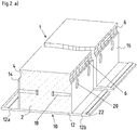
- Fig. 2a shows a perspective view of the support beam 1. It can be seen from this that the elastic damping elements 22 are located on the projections 12a, 12b essentially continuously along the longitudinal direction L.
- FIG. 1 shows a perspective view of the support beam 1. It can be seen from this that the elastic damping elements 22 are located on the projections 12a, 12b essentially continuously along the longitudinal direction L.
- the toothing 6 is designed here, for example, as a periodic longitudinal groove.
- Other embodiments can also provide the toothing outside the longitudinal groove.
- they are arranged at regular intervals along the longitudinal direction Through openings 20 shown through one of which the cross section of Fig. 1 is taken.
- Figure 2b shows another embodiment of the supporting beam 1 with the overhang 4 made of concrete or reinforced concrete and the connecting means formed there in the form of a toothing 6. These can be formed with or without the longitudinal groove.
- Figures 4a and 4b show an embodiment with a fire protection layer 17a, 17b.
- Figure 4a shows an embodiment in which a fire protection layer 17a is provided on the base plate 12, specifically inside the supporting beam 1 between the webs 14, 16.
- a fire protection layer 17b is arranged below the carrier 10 or the base plate 12, ie on the side of the carrier 10 or the base plate 12 facing away from the webs 14, 16.
- the fire protection layer 17b can also have a paint or be a paint itself.
- FIG. 5a shows a further embodiment for composite means according to the invention to achieve a form fit, namely corrugated metal sheets 19.
- corrugated metal sheets are also representative of other deformed sheet metal strips that can transmit composite forces through protrusions / recesses / surface contours. This can be, for example, twisted, folded or plastically deformed areas on the sheet metal strips.
- Figure 5b shows an embodiment in which the composite means according to the invention is realized by a bar or a perforated plate 21, the / the recesses 27 for Has absorption of transverse forces.
- the perforated plate 21 runs parallel to the web 14 and / or 16.
- Figure 5c shows a perforated plate 21 with recesses 27, which is arranged perpendicular to the web 14 and / or 16.
- Fig. 5d shows a further variant of the steel part of the supporting beam, in which the side web design 19, which is designed as a fold / bend, is arranged together with the base plate 12.
- the web 14 and / or 16 has folds and / or bends.
- Fig. 3 shows a ceiling system 100 according to the invention with the supporting beam 1 according to the invention and a semi-finished part 30 which is supported on the supporting beam 1.
- Composite elements 26, in particular reinforcing steel, were passed through the through opening 20 in the supporting beam.
- the connection area between the supporting beam 1 and the semi-finished part 30 is filled with in-situ concrete 50. It is in particular off Fig. 3a It can be seen that the in-situ concrete 50 does not penetrate into the through openings 20 of the supporting beam 1, but the supporting beam 1 is only filled with the concrete 2.
- the supporting beam 1 is first supported on supports (not shown), then the semi-finished part 30 is supported on the supporting beam 1, in particular the projections 12a, 12b.
- the composite elements 26 are then introduced into the through openings 20 of the supporting beam and a connecting area between the supporting beam 1 and the semi-finished part 30 is thus created.
- the in-situ concrete layer 50 is applied in the connection area between the supporting beam and the semi-finished part 30.
- the in-situ concrete 50 only penetrates into the through openings 20 of the supporting beam 1.
- the space between the webs is not filled with in-situ concrete 50 filled up, but has already been filled with concrete 2 during the production of the supporting beam.
- Figure 6 shows an embodiment having a hanger basket 25.
- Reinforcing steel in the form of longitudinal bars 23, 24, which extend in the longitudinal direction L, is arranged therein.
- the bracket cage 25 and the reinforcing steel 23, 24 are surrounded by concrete 2.
- the connecting means 18 extend through gaps in the bracket basket 25, as shown in FIG Figure 6 evident. This can strengthen the composite effect. In other words, the composite means 18 can be anchored even better in the concrete 2.
- the connecting means 18 and the through openings 20 are arranged at the same distance from the base plate 12.
- the composite means 18 and the through openings 20 are also in this embodiment, as for example in FIGS Figures 2a and 2 B for the embodiment of Figure 1 shown, arranged offset from one another in the longitudinal direction L.
- Damping elements 22 can be arranged on the projections 12a, 12b essentially continuously along the longitudinal direction L. Other arrangements of the damping elements 22, in particular those as described above, are also possible.
- the reinforcing bars 23, 24 running in the longitudinal direction L are preferably arranged in two planes, namely the reinforcing bars 23 in a plane E1, which is arranged on the (lower) side of the bracket cage 25 towards the base plate 12, and the reinforcing bars 24 in a plane E2 , which is arranged on the opposite (upper) side of the bracket basket 25, namely on the side of the protrusion 4.
- Six reinforcing bars 24 are preferably arranged in plane E2 and four reinforcing bars 23 are arranged in plane E1, which are located in Extend longitudinal direction L. Any other number is possible depending on the force required.
- the upper level E2 of the reinforcing steel 24 with the concrete 2 forms a reinforced pressure chord of the connecting beam.
Abstract
Die Erfindung betrifft einen Tragbalken in Verbundbauweise für Deckensysteme ebenfalls in Verbundbauweise, die zumindest abschnittsweise aus Beton bestehen, mit einem Träger, insbesondere Stahlträger, der eine Grundplatte und mindestens einen, vorzugsweise zwei, hierzu winkelig, vorzugsweise senkrecht, angeordneten Steg bzw. angeordnete Stege aufweist, dadurch gekennzeichnet, dass ein durch den Steg bzw. die Stege und die Grundplatte begrenzter Raum zumindest abschnittsweise mit Beton ausgefüllt ist.The invention relates to a support beam in composite construction for ceiling systems also in composite construction, which are at least partially made of concrete, with a support, in particular a steel support, which has a base plate and at least one, preferably two, angled, preferably perpendicular, web or webs , characterized in that a space delimited by the web or the webs and the base plate is at least partially filled with concrete.
Description
Die Erfindung betrifft einen Tragbalken für Deckensysteme nach dem Oberbegriff von Anspruch 1. Derartige Tragbalken kommen im Stahlbetonbau bzw. Verbundbau häufig zum Einsatz, insbesondere bei der Erstellung von Deckensystemen bzw. Geschossdecken.The invention relates to a support beam for ceiling systems according to the preamble of
Beispielsweise offenbart die
Derartige aus dem Stand der Technik bekannten Tragbalken haben sich bewährt. Bei Verbinden derartiger Tragbalkens mit dem Fertigteil oder Halbfertigteil ergeben sich aber oftmals Blasen im Beton unter der oberen Platte und der Beton ist insgesamt mit relativ viel Aufwand auf der Baustelle einzubringen. Auch ist die volle Tragfähigkeit des Tragbalkens erst nach Einbringen des Ortbetons gegeben. Des Weiteren wird im Obergurtbereich Stahl auf Druck belastet, was technische Nachteile bringt.Such supporting beams known from the prior art have proven themselves. When connecting such support beams to the prefabricated part or semi-finished part, however, bubbles often result in the concrete under the upper slab and the concrete as a whole has to be placed on the construction site with a relatively large amount of effort. The full load-bearing capacity of the girder is also only given after the in-situ concrete has been poured. Furthermore, steel is subjected to pressure in the upper chord area, which has technical disadvantages.
Es ist deshalb Aufgabe der vorliegenden Erfindung, bei einfacher Konstruktion einen Tragbalken vorzusehen, der eine einfache und zuverlässige Verwendung in Deckensystemen ermöglicht. Gleichzeitig soll das Gewicht des Tragbalkens gering gehalten werden.It is therefore the object of the present invention to provide a supporting beam with a simple construction which enables simple and reliable use in ceiling systems. At the same time, the weight of the supporting beam should be kept low.
Diese Aufgabe wird erfindungsgemäß durch den Tragbalken für Deckensysteme in Verbundbauweise mit den Merkmalen von Anspruch 1 gelöst. Demzufolge weist der Tragbalken einen Träger, insbesondere Stahlträger auf, der eine Grundplatte und mindestens einen, bevorzugt zwei, hierzu winklig, insbesondere senkrecht, angeordneten Steg bzw. angeordnete Stege aufweist. Der Tragbalken ist dadurch gekennzeichnet, dass ein durch den Steg bzw. die Stege und die Grundplatte, bevorzugt je aus Stahl, begrenzter Raum zumindest abschnittsweise mit Beton, der bevorzugt nicht Ortbeton ist, ausgefüllt ist bzw. der Raum zwischen dem Steg und der Grundplatte bzw. den Stegen und der Grundplatte zumindest abschnittsweise mit Beton, der insbesondere nicht Ortbeton ist, ausgefüllt ist. Stahl und Beton wirken hier in Verbundbauweise zusammen. In den Beton kann zur Übernahme von Kräften sowie zur Erhöhung der Verbundwirkung Betonstahl in Bügelform und als Stäbe eingelegt werden.According to the invention, this object is achieved by the support beam for ceiling systems in composite construction with the features of
Des Weiteren wird der Tragbalken in Verbundbauweise erfindungsgemäß in einem Deckensystem in Verbundbauweise verwendet, wobei der Tragbalken zum Abstützen mindestens eines Halbfertigteils oder Fertigteils verwendet wird und eine Ortbetonschicht, insbesondere außerhalb des Betons, der den durch den Steg bzw. die Stege und die Grundplatte begrenzten Raum bzw. den Raum zwischen dem Steg bzw. den Stegen und der Grundplatte zumindest abschnittsweise ausfüllt, zumindest im Verbindungsbereich zwischen dem mindestens einen Tragbalken und dem Halbfertigteil bzw. Fertigteil vorgesehen wird.Furthermore, the supporting beam in composite construction is used according to the invention in a ceiling system in composite construction, the supporting beam being used to support at least one semi-prefabricated part or prefabricated part and an in-situ concrete layer, in particular outside the concrete, which defines the space delimited by the web or the webs and the base plate or the space between the web or the webs and the base plate at least partially fills, is provided at least in the connection area between the at least one support beam and the semi-finished part or prefabricated part.
Des Weiteren ist erfindungsgemäß ein Deckensystem in Verbundbauweise vorgesehen, das zumindest einen erfindungsgemäßen Tragbalken, mindestens ein Halbfertigteil oder Fertigteil, das sich auf dem mindestens einen Tragbalken abstützt, und eine Ortbetonschicht aufweist, die zumindest im Verbindungsbereich zwischen dem mindestens einen Tragbalken und dem Halbfertigteil bzw. Fertigteil vorgesehen ist, insbesondere außerhalb des Betons, der den Raum zwischen dem Steg bzw. den Stegen und der Grundplatte bzw. den durch den Steg bzw. die Stege und die Grundplatte begrenzten Raum zumindest abschnittsweise ausfüllt.Furthermore, a ceiling system in composite construction is provided according to the invention, which has at least one supporting beam according to the invention, at least one semi-finished part or prefabricated part, which is supported on the at least one supporting beam, and an in-situ concrete layer, which at least in the connection area between the at least one supporting beam and the semi-finished part or Prefabricated part is provided, in particular outside the concrete, which at least partially fills the space between the web or the webs and the base plate or the space delimited by the web or the webs and the base plate.
Auch ist gemäß der Erfindung ein Verfahren zum Herstellen eines Deckensystems in Verbundbauweise vorgesehen, und zwar mit den Schritten Abstützen mindestens eines erfindungsgemäßen Tragbalkens auf Auflagern, Abstützen mindestens eines Halbfertigteils oder Fertigteils auf dem zumindest einen Tragbalken, Vorsehen von Verbundelementen im Verbindungsbereich zwischen dem mindestens einen Tragbalken und dem Halbfertigteil bzw. Fertigteil, Vorsehen einer Ortbetonschicht zumindest im Verbindungsbereich zwischen dem mindestens einen Tragbalken und dem Halbfertigteil bzw. Fertigteil, insbesondere außerhalb des Betons, der den Raum zwischen dem Steg bzw. den Stegen und der Grundplatte zumindest abschnittsweise ausfüllt.According to the invention, a method for producing a ceiling system in composite construction is provided, namely with the steps of supporting at least one supporting beam according to the invention on supports, supporting at least one semi-finished part or prefabricated part on the at least one supporting beam, providing composite elements in the connection area between the at least one supporting beam and the semi-finished part or prefabricated part, provision of an in-situ concrete layer at least in the connection area between the at least one supporting beam and the semi-finished part or prefabricated part, in particular outside the concrete, which at least partially fills the space between the web or webs and the base plate.
Dabei ist auch denkbar, dass der Tragbalken in und für die Verbundbauweise in mehreren Fertigungsschritten hergestellt wird. Beispielsweise kann das Einbringen von Bewehrungskörben bestehend aus Bügeln und Stabstählen und dann später von Beton in den Tragbalken zu einem späteren Moment erfolgen, sodass zunächst ein Halbfertigteil vorliegt, das zusätzlich zu dem Stahlträger Verbundmittel, insbesondere Formschlussmittel, zum Erzeugen eines Formschlusses mit dem einzufüllenden Beton aufweist.It is also conceivable that the supporting beam is produced in and for the composite construction in several production steps. For example, reinforcement cages consisting of stirrups and steel bars and then later concrete can be introduced into the supporting beam at a later moment, so that initially a semi-finished part is present that, in addition to the steel girder, has composite means, in particular form-fit means, for creating a form fit with the concrete to be filled .
Da der durch den Steg bzw. die Stege und die Grundplatte begrenzte Raum bzw. der Raum zwischen dem Steg bzw. den Stegen und der Grundplatte des Tragbalkens beim Aufstellen zumindest abschnittsweise mit Beton ausgefüllt ist, weist bereits der Tragbalken vor der Verbindung mit Halbfertigteilen bzw. Fertigteilen Beton auf. Mit anderen Worten ist der Beton zumindest abschnittsweise in diesem Raum vor der Verbindung mit dem Fertigteil bzw. Halbfertigteil vorgesehen, also bevor die Ortbetonschicht in dem Verbindungsbereich zwischen dem Tragbalken und dem Halbfertigteil bzw. Fertigteil vorgesehen wird. Der Tragbalken als solches weist also vor Verbindung mit dem Fertigteil oder Halbfertigteil im durch den Steg bzw. die Stege und die Grundplatte begrenzten Raum bzw. im Raum zwischen dem Steg bzw. den Stegen und der Grundplatte bereits zumindest abschnittsweise Beton auf, der kein Ortbeton ist. In einer bevorzugten Ausführungsform ist dieser Raum bis auf die Durchgangsöffnungen vollständig, um mögliche Stahlbewehrungen herum, mit Beton, der kein Ortbeton ist, ausgefüllt.Since the space delimited by the web or the webs and the base plate or the space between the web or the webs and the base plate of the supporting beam is at least partially filled with concrete when it is set up, the supporting beam already has before the connection with semi-finished parts or Precast concrete. In other words, the concrete is provided at least in sections in this space before the connection with the prefabricated part or semi-finished part, i.e. before the in-situ concrete layer is provided in the connection area between the supporting beam and the semi-finished part or prefabricated part. The support beam as such therefore already has at least some sections of concrete that is not in-situ concrete prior to connection with the prefabricated or semi-finished part in the space delimited by the web or the webs and the base plate or in the space between the web or the webs and the base plate . In a preferred embodiment, this space is completely filled, apart from the through openings, around possible steel reinforcements, with concrete that is not in-situ concrete.
Dadurch, dass der erfindungsgemäße Tragbalken in Verbundbauweise bereits während der Montage, also vor Verbinden mit dem Deckensystem durch Ortbeton, Beton aufweist, kann er die Last der Decke bzw. des Fertigteils oder Halbfertigteils bereits zuverlässig während der Montage tragen, und zwar über seine ganze Länge, ohne die Notwendigkeit, Zwischen- oder Hilfsstützen zu verwenden. Dadurch wird die Herstellung des Deckensystems vereinfacht und insbesondere Nachfolge- und Parallelarbeiten können vereinfacht und beschleunigt durchgeführt werden. Insbesondere ist eine Druckzone bereits im Lieferzustand vorhanden; selbst zum Auflegen von Deckenelementen ist dann keine zusätzliche Unterstützung erforderlich, da die Druckzone durch den Beton mit oder ohne Bewehrung bereits (bevorzugt vollständig) ausgebildet ist.The fact that the supporting beam according to the invention in composite construction already has concrete during assembly, that is to say before connection to the ceiling system by in-situ concrete, it can withstand the load of the ceiling or of the prefabricated part or semi-finished part reliably during assembly, over its entire length without the need to use intermediate or auxiliary supports. This simplifies the production of the ceiling system and, in particular, subsequent and parallel work can be carried out in a simplified and accelerated manner. In particular, a pressure zone is already present in the delivery state; No additional support is then required even for laying ceiling elements, since the pressure zone is already (preferably completely) formed by the concrete with or without reinforcement.
Die Konstruktionshöhe des Tragbalkens entspricht der Höhe des Deckensystems plus der Dicke der Grundplatte. Somit kann die Konstruktionshöhe des Deckensystems minimiert werden, was zur Verkleinerung des Bauvolumens führt, ohne gleichzeitig die Nutzungsfläche reduzieren zu müssen. In besonderen Fällen ist es auch denkbar, den Deckenbalken und die seitlich aufgelegten Deckenelemente durch eine darüber gegossene Ortbetonschicht mit Hilfe darüber gelegter Bewehrung kraftschlüssig als Deckenscheibe zu verbinden. In diesem Fall ist die Deckenhöhe dann über dem Deckenbalken um die Ortbetonschicht höher.The construction height of the supporting beam corresponds to the height of the ceiling system plus the thickness of the base plate. In this way, the construction height of the ceiling system can be minimized, which leads to a reduction in the construction volume without having to reduce the usable area at the same time. In special cases it is also conceivable to connect the ceiling beams and the laterally applied ceiling elements in a non-positive manner as a ceiling pane by means of an in-situ concrete layer poured over it with the help of reinforcement laid over it. In this case, the ceiling height above the ceiling beam is higher by the layer of in-situ concrete.
Dadurch, dass neben Stahl auch Beton bereits in dem vorgefertigten Tragbalken verwendet wird, kann die Anordnung von Stahl und Beton im Tragbalken hinsichtlich der Anforderungen an die Druckfestigkeit optimiert werden. Dies, da der durch den Steg bzw. die Stege und die Grundplatte begrenzte Raum bzw. der Raum zwischen dem Steg bzw. den Stegen und der Grundplatte zumindest abschnittsweise mit Beton, der bevorzugt nicht Ortbeton ist, ausgefüllt ist, die Druckzone des Balkens für den Verkehrslastfall ist. Die Verwendung von Beton anstelle eines Stahlgurtes reduziert das Gewicht des Tragbalkens.
Der Erfindung liegt der Gedanke zu Grunde, einen Tragbalken in Deckensystemen zu verwenden, wobei der Tragbalken als Verbundbauteil selbst bereits vor der Verbindung mit dem Deckensystem Beton aufweist. Da der Tragbalken als vorgefertigtes Verbundteil als solches nicht nur Stahl, sondern bereits Beton aufweist, kann er auch als "Hybridbalken" angesehen werden. Als sogenannter Stahl-Beton-Verbundbalken (oder "Verbundbalken") wird die Zugbeanspruchung durch den Stahlanteil und die Druckbeanspruchung großteils durch den Betonanteil übernommen. Starke Kräfte können durch eingelegte Druckbewehrung aufgenommen werden.Because concrete is also used in the prefabricated supporting beam in addition to steel, the arrangement of steel and concrete in the supporting beam can be optimized with regard to the requirements for compressive strength. This is because the space or the space between the web or the webs and the base plate bounded by the web or the webs and the base plate is at least partially filled with concrete, which is preferably not in-situ concrete, the pressure zone of the beam for the Traffic load case is. The use of concrete instead of a steel belt reduces the weight of the support beam.
The invention is based on the idea of using a supporting beam in ceiling systems, the supporting beam as Composite component itself already has concrete before it is connected to the ceiling system. Since the supporting beam as a prefabricated composite part as such has not only steel but also concrete, it can also be viewed as a "hybrid beam". As a so-called steel-concrete composite beam (or "composite beam"), the tensile stress is taken over by the steel component and the compressive stress is largely taken over by the concrete component. Strong forces can be absorbed by inserted pressure reinforcement.
Unter der Grundplatte ist insbesondere der Untergurt zu verstehen. Die Grundplatte und der dazu winklig angeordnete Steg bzw. die dazu winklig angeordneten Stege, die von derselben Seite der Grundplatte vorstehen, definieren den Raum, in dem zumindest abschnittsweise der Beton vorgesehen ist. Vorzugsweise ist die Anordnung der Grundplatte und der Stege im Querschnitt senkrecht zur Längsrichtung des Tragbalkens U-förmig.The base plate is to be understood in particular as the lower chord. The base plate and the web arranged at an angle thereto or the webs arranged angled thereto and protruding from the same side of the base plate define the space in which the concrete is provided at least in sections. The arrangement of the base plate and the webs is preferably U-shaped in cross section perpendicular to the longitudinal direction of the support beam.
Eine mögliche Form sieht auch einen Steg mittig mit der Grundplatte darunter in einem Betonbalken vor. Dabei wird dann der Raum zur Erzeugung des Betonbalkens durch eine beidseitige Hilfsschalung definiert. Auch sind mehr als zwei Stege, also beispielsweise ein Zentralsteg und zwei seitliche Stege, zur seitlichen Raumbegrenzung ausführbar.One possible shape also provides a web in the middle with the base plate below in a concrete beam. The space for creating the concrete beam is then defined by auxiliary formwork on both sides. It is also possible to implement more than two webs, for example a central web and two lateral webs, to delimit space at the side.
Die Grundplatte kann durch querlaufende Rippenstege seitlich ausgesteift werden und so mehr Tragkraft erhalten. Diese Rippenstege sind dann durch Aussparungen oder Begrenzungen, Abmessungen mit den aufzulegenden Deckenelementen abzustimmen, so dass diese trotzdem auf der Grundplatte aufliegen können.The base plate can be laterally stiffened by transverse rib webs and thus receive more load-bearing capacity. These rib webs are then to be coordinated with the ceiling elements to be placed by means of cutouts or boundaries, dimensions, so that they can nevertheless rest on the base plate.
Bei dem Beton handelt es sich um einen beliebigen Beton, vorzugsweise einen hochfesten Beton, beispielsweise SVB. Insbesondere kann ein Beton der Klasse C 60/75 mit chemischen Plastifizierern als Zusatzmittel oder Kohlefasern bzw. Glasfasern vermischt verwendet werden. Der Beton ist vorzugsweise hochfester Beton (Zylinderfestigkeit zwischen 50 N/mm2 und 100 N/mm2 (C 100/115)). Der Beton kann Stahlbeton (vorzugsweise mit Betonstahlbügeln und -stäben hochbewehrter Stahlbeton) sein. Die Betonfüllung also kann mit oder ohne Bewehrung ausgeführt sein.The concrete is any concrete, preferably a high-strength concrete, for example SCC. In particular, a class C 60/75 concrete can with chemical Plasticizers can be used as additives or mixed carbon fibers or glass fibers. The concrete is preferably high-strength concrete (cylinder strength between 50 N / mm 2 and 100 N / mm 2 (
Zur Verbundwirkung zwischen Beton und Stahl sind zusätzliche Verbundmittel angeordnet. Diese können durch Formgebung der Stahlteile und/oder durch zusätzlich aufgebrachte Verbundkörper wie Kopfbolzen, Lochblechstreifen und/oder strukturierte Teile gebildet werden, die Kräfte zwischen Beton und Stahl übertragen.To create a bond between concrete and steel, additional bonding agents are arranged. These can be formed by shaping the steel parts and / or by additionally applied composite bodies such as head bolts, perforated sheet metal strips and / or structured parts that transfer forces between concrete and steel.
Weitere vorteilhafte Weiterbildungen sind in den abhängigen Ansprüchen angegeben.Further advantageous developments are given in the dependent claims.
Es ist bevorzugt, dass der mit dem Beton zumindest abschnittsweise gefüllte Raum auf der von der Grundplatte abgewandten Seite zumindest bereichsweise, bevorzugt vollständig, offen ist. Mit anderen Worten ist der Träger bevorzugt frei von einer zur Grundplatte parallel verlaufenden oberen Stahlplatte, also eines Obergurts aus Stahl, der den Raum zwischen den Stegen und der Grundplatte begrenzt, sodass der Raum ohne gegenüberliegende Platte als offen bezeichnet wird. Auf den Stahlobergurt kann also verzichtet werden.It is preferred that the space filled with the concrete at least in sections is open at least in some areas, preferably completely, on the side facing away from the base plate. In other words, the carrier is preferably free of an upper steel plate running parallel to the base plate, i.e. an upper belt made of steel, which delimits the space between the webs and the base plate, so that the space without an opposing plate is referred to as open. The steel belt can therefore be dispensed with.
Diese Ausführungsform hat den Vorteil gegenüber der Verwendung einer zusätzlichen oberen Platte, also eines Stahlobergurts, dass durch die Verwendung von weniger Stahl das Gewicht des Tragbalkens reduziert wird. Im Übrigen ist die Verwendung von Beton in diesem Druckbereich vorteilhaft, da Stahl weniger druckstabil als Beton ist. Somit liegt in dieser Ausführungsform im Druckbereich keine Platte, also kein Obergurt, aus Stahl vor, sondern der druckstabilere Beton.This embodiment has the advantage over the use of an additional upper plate, that is to say a steel belt, that the weight of the supporting beam is reduced by using less steel. In addition, the use of concrete in this pressure range is advantageous because steel is less pressure-resistant than concrete. Thus, in this embodiment, there is no plate in the pressure area, ie no upper chord, made of steel in front, but the more pressure-resistant concrete.
Auch kann dadurch, dass der mit Beton zu füllende Raum auf der von der Grundplatte abgewandten Seite zumindest bereichsweise, bevorzugt vollständig, offen ist, der Beton leichter eingefüllt werden, nämlich direkt von oben, statt seitlich durch die Stege. Dies führt dazu, dass sich keine Blasen im Beton bilden, wodurch die Herstellung eines solchen Tragbalkens weiter einfacher und zuverlässiger wird.Also, because the space to be filled with concrete is at least partially, preferably completely, open on the side facing away from the base plate, the concrete can be filled more easily, namely directly from above instead of laterally through the webs. This means that no bubbles form in the concrete, which makes the manufacture of such a supporting beam further easier and more reliable.
Darüber hinaus ist es möglich, zusätzliche, parallel zur Längsrichtung des Tragbalkens in dem Raum zwischen den Stegen verlaufende Bewehrungen wie Armierungsstäbe aus Stahl - auch mit Bügeln zu Körben gebunden - leichter einzusetzen, weil der Raum zumindest bereichsweise bzw. vollständig von oben offen und damit zugänglich ist.In addition, it is possible to use additional reinforcements running parallel to the longitudinal direction of the girder in the space between the webs, such as steel reinforcing bars - also tied to baskets with brackets - because the space is at least partially or completely open from above and therefore accessible is.
Weiter vorzugsweise steht der Beton über mindestens einen Steg um einen Überstand hervor, wobei sich vorzugsweise der Überstand in eine Richtung senkrecht zur Grundplatte erstreckt. Vorzugsweise ist der Überstand so bemessen, dass der Überstand bündig zur Deckenplatte ist. Dann ist es nicht nötig, Aufbeton vorzusehen. Der Überstand kann ein Stahlbetonkörper sein.More preferably, the concrete protrudes over at least one web by an overhang, the overhang preferably extending in a direction perpendicular to the base plate. The overhang is preferably dimensioned in such a way that the overhang is flush with the ceiling plate. Then it is not necessary to provide concrete. The overhang can be a reinforced concrete body.
Weiter vorzugsweise weist der Überstand eine Verzahnung, insbesondere eine Längsnut, auf. Diese Verzahnung kann die horizontalen Querkräfte aufnehmen. Die Verzahnung dient auch dazu, eine Gesamttragwirkung zwischen dem Tragbalken und den aufgelegten Deckenelementen als steife Deckenscheibe auszubilden. In besonderen Fällen ist das Aufbringen zusätzlicher Ortbetonschichten zur Erzielung höherer Deckensteifigkeit möglich.Furthermore, the protrusion preferably has a toothing, in particular a longitudinal groove. These teeth can absorb the horizontal transverse forces. The toothing also serves to create an overall load-bearing effect between the supporting beam and the ceiling elements placed on it as a rigid ceiling pane. In special cases, it is possible to apply additional in-situ concrete layers to achieve higher ceiling rigidity.
Eine Ausführungsform kann einen Bügelkorb aufweisen. Darin kann Armierungsstahl, bevorzugt in Form von Längsstäben, angeordnet sein. Der Bügelkorb und der Armierungsstahl können von Beton zumindest abschnittsweise, bevorzugt vollständig, umgeben sein. Diese Anordnung von Bewehrung im Zusammenwirken mit dem umgebenden Beton stellt dann Stahlbeton dar, der den durch den Steg bzw. die Stege und die Grundplatte begrenzten Raum zumindest abschnittsweise ausfüllt.One embodiment can have a hanger basket. Reinforcing steel, preferably in the form of longitudinal bars, be arranged. The bracket cage and the reinforcing steel can be surrounded by concrete at least in sections, preferably completely. This arrangement of reinforcement in cooperation with the surrounding concrete then represents reinforced concrete which at least partially fills the space delimited by the web or the webs and the base plate.
Die Verbundmittel können sich durch Zwischenräume in dem Bügelkorb in der Richtung quer zur Längsrichtung L, also in Querrichtung, hindurch erstrecken. Dadurch kann die Verbundwirkung verstärkt werden.The connecting means can extend through intermediate spaces in the bracket basket in the direction transverse to the longitudinal direction L, that is to say in the transverse direction. This can strengthen the composite effect.
Vorzugsweise weisen die Innenflächen des bzw. der Stege, also die Flächen, die innenseitig den Raum zwischen den Stegen definieren, und/oder die Grundplatte, also die Seite der Grundplatte, die innenseitig den Raum zwischen den Stegen und der Grundplatte definiert, Verbundmittel auf. Dies kann auch bedeuten, dass der Steg bzw. die Stege und/oder die Grundplatte selbst so ausgestaltet sind, dass sie als Verbundmittel wirken. Verbundmittel können auch integral oder zusätzlich an der Innenfläche des bzw. der Stege und/oder der Grundplatte angeordnet sein. Verbundmittel verbessern die Verbindung zwischen dem Träger und dem Beton.Preferably, the inner surfaces of the web or webs, i.e. the surfaces that define the space between the webs on the inside, and / or the base plate, i.e. the side of the base plate that defines the space between the webs and the base plate on the inside, have bonding agents. This can also mean that the web or the webs and / or the base plate itself are designed in such a way that they act as a connecting means. Composite means can also be arranged integrally or additionally on the inner surface of the web or webs and / or the base plate. Bonding agents improve the bond between the beam and the concrete.
Weiter vorzugsweise weist das Verbundmittel Formschlussmittel auf, insbesondere Kopfbolzen. Diese können sich insbesondere winklig von den Stegen in den Raum erstrecken, weiter vorzugsweise im Wesentlichen parallel zu der Grundplatte und senkrecht zu den zur Grundplatte senkrecht angeordneten Stegen. Alternativ oder zusätzlich können auch Verbundbolzen von der Grundplatte vorzugsweise parallel zu den Stegen verlaufend vorgesehen sein und/oder mehrere Verbundbolzen, die sich von einem Steg vorzugsweise senkrecht zur Grundplatte erstrecken und bezüglich ihres Abstandes zur Grundplatte variabel sind, vorzugsweise verschiebbar entlang des Stegs, sind.The composite means also preferably has form-fitting means, in particular headed bolts. These can in particular extend at an angle from the webs into the space, further preferably essentially parallel to the base plate and perpendicular to the webs arranged perpendicular to the base plate. Alternatively or additionally, composite bolts can also be provided from the base plate, preferably running parallel to the webs, and / or several composite bolts, which extend from a web, preferably perpendicular to the base plate and are variable with regard to their distance from the base plate, preferably displaceable along the web.
Allgemein können Verbundmittel zur Ausbildung eines Formschlusses beliebig verwirklicht sein, solange sie, und damit die Stege und/oder die Grundplatte, zur Aufnahme und Übertragung von Verbund-Querkräften ausgestaltet sind. Sie können beispielsweise Vertiefungen und/oder Vorsprünge sein, die eine Verzahnung zwischen den Stegen bzw. der Grundplatte und dem Beton ermöglichen. Denkbar ist insbesondere eine wellenförmige Form an der Innenseite der Stege bzw. Grundplatte, beispielsweise dadurch, dass entsprechend wellenförmige Bleche oder über die Längsrichtung gelochte, tordierte oder andersartig strukturierte Blechstreifen mit krafteinleitender Wirkung als Verbundmittel innenseitig angeordnet und an die Stege bzw. die Grundplatte angeschweißt sind. Eine weitere Möglichkeit ist eine Leiste mit Aussparungen.In general, composite means for forming a form fit can be implemented as desired, as long as they, and thus the webs and / or the base plate, are designed to absorb and transmit composite transverse forces. They can, for example, be depressions and / or projections that enable a toothing between the webs or the base plate and the concrete. In particular, a wave-like shape is conceivable on the inside of the webs or base plate, for example in that correspondingly wave-shaped sheets or sheet metal strips with a force-introducing effect as a composite material that are perforated, twisted or otherwise structured in the longitudinal direction are arranged on the inside and welded to the webs or the base plate . Another option is a bar with cutouts.
Diese Ausführungen von Verbundmitteln als Leiste bzw. Streifen haben den weiteren Vorteil gegenüber einzelnen Kopfbolzen, dass sie kontinuierlich bzw. streifenförmig an den Steg bzw. die Grundplatte über die gesamte gewünschte Länge aufgebracht werden können, d.h. es ist nicht nötig, mehrere einzelne Verbundmittel an den Stegen bzw. der Grundplatte einzeln anzubringen bzw. anzuschweißen.These designs of composite means as a bar or strip have the further advantage over individual head bolts that they can be applied continuously or in strip form to the web or the base plate over the entire desired length, ie it is not necessary to attach several individual composite means to the Bars or the base plate to be attached or welded individually.
Dies hat insbesondere gegenüber einzeln angeschweißten Verbundbolzen wirtschaftliche Vorteile und die Krafteinleitung ist nicht auf Einzelpunkte beschränkt, sondern verteilt, was die Ausnutzbarkeit erhöht.This has economic advantages, in particular compared to individually welded-on composite bolts, and the introduction of force is not limited to individual points, but rather distributed, which increases the usability.
Besonders vorteilhaft ist es, wenn die einzelnen Elemente des Tragbalkens selbst durch entsprechende Formgebung, beispielsweise wie Wellung, Faltungen, Eindrückungen oder andere Formen, im Zusammenspiel mit dem Beton Kräfte besonders in Längsrichtung zwischen Beton und Stahlteilen überträgt. Dies gilt in gleichem Maße sowohl für den Beton im Tragbalken als auch für einen möglichen Vergussbeton oder Aufbeton zwischen oder auf den aufgelegten Deckenelementen. Dazu kann der Tragbalken auch höher als die aufgelegten Deckenelemente sein.It is particularly advantageous if the individual elements of the supporting beam themselves by appropriate shaping, for example such as corrugation, folds, indentations or other shapes, in interaction with the concrete, transmit forces especially in the longitudinal direction between concrete and steel parts. This applies equally to both the concrete in the supporting beam and a possible grouting concrete or Concrete between or on the laid ceiling elements. For this purpose, the supporting beam can also be higher than the ceiling elements placed on top.
In einer besonderen Ausführungsform sind die Stege an der oberen Seite durch einen vorgelagerten örtlichen Formgebungsprozess gewellt oder gefaltet ausgeführt. Dies hilft nicht nur, die Verbundkräfte zwischen Beton und Stahl zu übertragen, sondern es ermöglicht auch, die Seitenstege vor dem Anschweißen an die Grundplatte in sich zu biegen oder wölben, um einen gekrümmten Tragbalken zu erzeugen. Daher kommt einer leichten Herstellbarkeit eine wirtschaftliche und technische Bedeutung zu.In a particular embodiment, the webs are designed to be corrugated or folded on the upper side by an upstream local shaping process. This not only helps to transfer the bond forces between concrete and steel, but it also makes it possible to bend or arch the side bars before welding them to the base plate in order to create a curved supporting beam. Ease of manufacture is therefore of economic and technical importance.
Vorzugsweise kann der Tragbalken einer Überhöhung aufweisen, die bevorzugt einer späteren Durchbiegung entspricht. Diese mit sogenannter Überhöhung hergestellten Tragbalken haben für die wahrnehmbare kleine Durchbiegung im fertigen Bauwerk Vorteile, weil sich die Durchbiegung beim Aufbringen der Deckenelemente und die Überhöhung quasi aufheben. In jedem Falle, ob mit verformten oberen Stegelementen oder ebenen Stegelementen, ist dies bei einem Tragbalken ohne Stahlobergurt einfacher herstellbar als mit Obergurt, weil weniger Teile gehalten und verschweißt werden müssen.The supporting beam can preferably have an elevation which preferably corresponds to a later deflection. These supporting beams, which are produced with so-called canting, have advantages for the perceptible small deflection in the finished structure, because the deflection when the ceiling elements are applied and the canting are more or less canceled out. In any case, whether with deformed upper web elements or flat web elements, this is easier to produce with a supporting beam without a steel belt than with an upper belt, because fewer parts have to be held and welded.
Eine Anordnung von mehreren Leisten oder Blechen in horizontaler oder vertikaler Richtung, nebeneinander, beispielsweise parallel, und/oder in unterschiedlicher Tiefe von Wellen bzw. Vorsprüngen und Vertiefungen ist beliebig gestaltbar.An arrangement of several strips or sheets in the horizontal or vertical direction, next to one another, for example parallel, and / or at different depths of corrugations or projections and depressions can be designed as desired.
Der Tragbalken kann des Weiteren Durchgangsöffnungen aufweisen, die sich quer zur Längsachse des Tragbalkens durch die Stege und bevorzugt auch durch den im Raum vorgesehenen Beton erstrecken. Diese, meist sich periodisch wiederholenden Durchgangsöffnungen dienen zur Aufnahme von Verbundelementen, die im Verbindungsbereich zwischen dem Tragbalken und dem Halbfertigteil bzw. Fertigteil vorgesehen sind. Dadurch können die Scherkräfte im Deckensystem zuverlässig aufgenommen werden.The supporting beam can furthermore have through openings which extend transversely to the longitudinal axis of the supporting beam through the webs and preferably also through the concrete provided in the room. These, mostly periodically repeating through openings are used to accommodate composite elements that are in the connection area between the supporting beam and the Semi-finished part or finished part are provided. This means that the shear forces in the ceiling system can be reliably absorbed.
Auch die Aufnahme oder Durchschiebung von Bewehrungsstahl ist möglich. Dies kann dazu dienen, eine aussteifende Deckenscheibenwirkung zu erzielen. Dies kann je nach Höhenanordnung der Durchbrechungen durch hervorstehende Bewehrungsstähle in den Deckenelementen oder darüber gelegte Bewehrungen geschehen.Reinforcing steel can also be picked up or pushed through. This can serve to achieve a stiffening ceiling pane effect. Depending on the height of the openings, this can be done by protruding reinforcing steel in the ceiling elements or by reinforcement placed on top.
Vorzugsweise haben die Verbundmittel bzw. Bolzen mindestens den gleichen Abstand zur Grundplatte wie die Durchgangsöffnungen. Ein größerer Abstand der Verbundmittel bzw. Formschlussmittel zur Grundplatte als zum Überstand ist denkbar. Dies ist im Brandfall vorteilhaft.The connecting means or bolts preferably have at least the same distance from the base plate as the through openings. A greater distance between the composite means or form-fit means from the base plate than from the protrusion is conceivable. This is advantageous in the event of a fire.
Die Ortbetonschicht des Deckensystems ist also vorzugsweise seitlich von den Stegen um die Verzahnung herum und durch die Durchgangsöffnungen in dem Tragbalken vorgesehen und vorzugsweise zumindest teilweise oberhalb. Unter dem Verbindungsbereich zwischen dem Tragbalken und dem Halbfertigteil bzw. Fertigteil sind insbesondere der Bereich der Durchgangsöffnungen des Tragbalkens sowie der obere Bereich zu verstehen, in dem der Überstand die Verzahnung aufweist.The in-situ concrete layer of the ceiling system is therefore preferably provided to the side of the webs around the toothing and through the through openings in the supporting beam and preferably at least partially above. The connection area between the supporting beam and the semi-finished part or prefabricated part is to be understood in particular as the area of the through openings of the supporting beam and the upper area in which the protrusion has the toothing.
Zusätzlich kann die Grundplatte mindestens einen Vorsprung aufweisen, der quer zur Längsachse des Tragbalkens über mindestens einen Steg hervorsteht, wobei bevorzugt auf dem zumindest einen Vorsprung ein elastisches Dämpfungselement vorgesehen ist. Weiter vorzugsweise sind sie auf beiden Seiten der Stege, die außenseitig zu dem Raum liegen, der durch die beiden Stege definiert ist, vorgesehen. Es ist also angedacht, dass die Stege nach innen von den Rändern der Grundplatte versetzt angeordnet sind, sodass die Bereiche der Grundplatte außerhalb der Stege als Vorsprünge dienen.In addition, the base plate can have at least one projection which protrudes transversely to the longitudinal axis of the supporting beam via at least one web, an elastic damping element preferably being provided on the at least one projection. More preferably, they are provided on both sides of the webs which are on the outside of the space defined by the two webs. It is therefore envisaged that the webs are arranged offset inwards from the edges of the base plate, so that the areas of the base plate outside the webs serve as projections.
Auf dem Vorsprung bzw. den Vorsprüngen kann ein Fertigteil bzw. Halbfertigteil, insbesondere eine Deckenplatte, abgestützt werden. Wenn zusätzlich ein elastisches Dämpfungselement vorgesehen ist, wird die Auflage optimiert. Das Dämpfungselement kann beispielsweise ein Elastomer in einer Stärke von 3-5 mm, einer Breite von bevorzugt mehr als 30 mm sein, das eine Tragfähigkeit von bis zu 15 N/mm2 aufweist. Das Dämpfungselement kann durchgängig und/oder linienförmig ausgebildet sein; es kann auch punktuell ausgebildet sein.A prefabricated part or semi-finished part, in particular a ceiling plate, can be supported on the projection or projections. If an elastic damping element is also provided, the support is optimized. The damping element can, for example, be an elastomer with a thickness of 3-5 mm, a width of preferably more than 30 mm, which has a load-bearing capacity of up to 15 N / mm 2 . The damping element can be continuous and / or linear; it can also be formed selectively.
Zur Verbesserung der Gebrauchstauglichkeit bei Brandlasten kann die Grundplatte bzw. der Träger eine Brandschutzschicht aufweisen. Vorzugsweise ist diese zumindest abschnittsweise in dem Raum zwischen den Stegen - also im Tragbalken - auf der Grundlatte aufgebracht, wobei diese Schicht vor dem Vorsehen von Beton in dem Raum zwischen den Stegen angeordnet wird. Besonders wirksam, alternativ oder zusätzlich, kann eine Brandschutzschicht auch außen, also auf der den Stegen abgewandten Seite der Grundplatte bzw. auf der Unterseite der Grundplatte, zumindest abschnittsweise entlang der Grundplatte aufgebracht sein. Die Brandschutzschicht kann beispielsweise eine Brandschutzbauplatte PROMATECT® oder ein Schaumbildner sein. Die Brandschutzschicht kann ein Anstrich sein oder einen solchen aufweisen.To improve the usability in the event of fire loads, the base plate or the carrier can have a fire protection layer. This is preferably applied at least in sections in the space between the webs - that is, in the supporting beam - on the base lath, this layer being arranged in the space between the webs before the provision of concrete. A fire protection layer can also be applied particularly effectively, alternatively or additionally, on the outside, that is to say on the side of the base plate facing away from the webs or on the underside of the base plate, at least in sections along the base plate. The fire protection layer can, for example, be a PROMATECT® fire protection building board or a foaming agent. The fire protection layer can be a paint or have such a paint.
Damit kann besonders effektiv die die Zugkraft des Biegebalkens übertragende Stahlgrundplatte vor Überhitzung und vorzeitigem Versagen bei Beflammung von unten geschützt werden. Wirtschaftlich ist dabei die selektive Anordnung der teuren Brandschutzmaßnahmen nur im Bereich der größten Einwirkung.In this way, the steel base plate transmitting the tensile force of the bending beam can be protected particularly effectively against overheating and premature failure in the event of a flame from below. The selective arrangement of the expensive fire protection measures is only economical in the area of greatest impact.
Weitere Merkmale und Vorteile der Erfindung werden anhand der nachfolgenden ausführlichen Beschreibung noch näher ersichtlich werden.Further features and advantages of the invention will become even more apparent from the following detailed description.
-
Fig. 1 zeigt einen erfindungsgemäßen Tragbalken in Verbundbauweise in einer Querschnittsansicht senkrecht zur Längsrichtung des Tragbalkens; die Betonfüllung kann mit oder ohne Bewehrung ausgeführt sein.Fig. 1 shows a supporting beam according to the invention in composite construction in a cross-sectional view perpendicular to the longitudinal direction of the supporting beam; the concrete filling can be carried out with or without reinforcement. -
Fig. 2a zeigt eine perspektivische Ansicht des erfindungsgemäßen Tragbalkens mit Beton- oder Stahlbetonfüllung.Fig. 2a shows a perspective view of the support beam according to the invention with concrete or reinforced concrete filling. -
Fig. 2b zeigt eine weitere Ausführungsform des erfindungsgemäßen Tragbalkens.Figure 2b shows a further embodiment of the support beam according to the invention. -
Fig. 3 zeigt erfindungsgemäße Deckensysteme, wobeiFig. 3a die Verbindung eines erfindungsgemäßen Tragbalkens mit einer Hohlkastenplatte undFig. 3b die Verbindung eines erfindungsgemäßen Tragbalkens mit einer Verbunddecke bestehend aus Elementdecken als Halbfertigteil mit Gitterträgerbewehrung und Aufbeton zeigt;Fig. 3 shows ceiling systems according to the invention, whereinFig. 3a the connection of a support beam according to the invention with a box girder slab andFigure 3b shows the connection of a support beam according to the invention with a composite ceiling consisting of element ceilings as a semi-finished part with lattice girder reinforcement and concrete; -
Fig. 4a und 4b zeigen einen erfindungsgemäßen Tragbalken in einer Querschnittsansicht senkrecht zur Längsrichtung des Tragbalkens mit einer Brandschutzschicht.Figures 4a and 4b show a supporting beam according to the invention in a cross-sectional view perpendicular to the longitudinal direction of the supporting beam with a fire protection layer. -
Fig. 5a, 5b und 5c zeigen weitere Ausführungsformen von Verbundmitteln gemäß der vorliegenden Erfindung.Figures 5a, 5b and 5c show further embodiments of composite means according to the present invention. -
Fig. 5d zeigt eine Ausführungsform des Stahlteils des Tragbalkens mit einer Verzahnung der Stege durch Falten oder Biegen als linienförmig angeordnetes Verbundmittel wie sie in anderen Ausführungsformen inFiguren 5a, b und c gezeigt sind.Fig. 5d FIG. 11 shows an embodiment of the steel part of the supporting beam with a toothing of the webs by folding or bending as a linearly arranged composite means as in other embodiments in FIGFigures 5a, b and c are shown. -
Fig. 6 zeigt einen erfindungsgemäßen Tragbalken in einer Querschnittsansicht senkrecht zur Längsrichtung des Tragbalkens.Fig. 6 shows a support beam according to the invention in a cross-sectional view perpendicular to the longitudinal direction of the support beam.
Bevorzugte Ausführungsformen der vorliegenden Erfindung werden nachfolgend ausführlich unter Bezugnahme auf die begleitenden Zeichnungen beschrieben.Preferred embodiments of the present invention will hereinafter be described in detail with reference to the accompanying drawings.
Die beiden Stege 14, 16 und die Grundplatte 12 definieren einen Raum, der mit Beton 2 ausgefüllt ist. Die Seite, auf der der Raum, der durch die Stege 14, 16 und die Grundplatte 12 begrenzt wird, offen ist, liegt der Grundplatte gegenüber. Über diese der Grundplatte 12 abgewandten Seite steht ein Überstand 4 über den durch die Stege 14, 16 und die Grundplatte 12 definierten Raum hervor. Dieser Überstand 4 erstreckt sich senkrecht zur Grundplatte 12 und innerhalb einer gedachten Fortsetzung der Stege 14, 16, also parallel zu diesen.The two
Auf den Seiten quer zur Längsrichtung L des Tragbalkens weist der Überstand 4 eine Verzahnung 6 auf. In der Querschnittsansicht von
Des Weiteren ist an der Innenfläche der Stege 14, 16, also der Fläche, die den Raum zwischen den Stegen definiert, ein Verbundmittel 18 vorgesehen, das als Kopfbolzen ausgebildet ist und zur formschlüssigen Verbindung mit dem Beton 2 dient. Der Kopfbolzen 18 erstreckt sich von den Stegen 14, 16 senkrecht und parallel zur Grundplatte 12 zu jeweils etwa einem Viertel der Ausdehnung des Raums zwischen den Stegen entlang der Querrichtung des Tragbalkens 12 in den Beton 2. In
Die Querrichtung verläuft senkrecht zur Längsrichtung L des Tragbalkens 1 und somit in
Eine alternative oder zusätzliche, nicht gezeigte Anordnung von Bolzen besteht darin, dass sich die Bolzen 18 von der Grundplatte 12 aus parallel zu den Stegen 14, 16 erstrecken und/oder sich mehrere Bolzen von einem Steg 14, 16 aus parallel zur Grundplatte 12 aus erstrecken und dabei vorzugsweise der Abstand der Bolzen 18 relativ zur Grundplatte 12 bzw. zueinander variabel ist, insbesondere die Bolzen an dem Steg 14, 16 verschiebbar angeordnet sind, sodass die Bolzen 18 beispielsweise wechselnd mittig oder oben in dem Tragbalken 1 angeordnet sein können.An alternative or additional arrangement of bolts, not shown, consists in the
Anders als in
Durchgangsöffnungen 20 erstrecken sich quer zur Längsachse L des Tragbalkens 1, also in Querrichtung, durch die Stege 14, 16 und durch den Beton 2 hindurch, der zwischen den Stegen eingefüllt ist.Through
Anders als in
Die Grundplatte weist zwei Vorsprünge 12a, 12b auf, die quer zur Längsachse des Tragbalkens, also in Querrichtung, verlaufen. Diese Vorsprünge entsprechen den Randbereichen der Grundplatte 12 in der Querrichtung des Tragbalkens 1.The base plate has two
Auf den beiden Vorsprüngen 12a, 12b ist jeweils ein elastisches Dämpfungselement 22 auf der Seite der Grundplatte 12 vorgesehen, die zu den Stegen 14, 16 hinzeigt. Auf diese Dämpfungselementen 22 wird das Halbfertigteil bzw. Fertigteil aufgelegt. Das elastische Dämpfungselement 22 kann in Längsrichtung L durchgängig ausgebildet sein. Es wirkt lastzentrierend.An elastic damping
Des Weiteren ist ersichtlich, dass die Verzahnung 6 hier beispielhaft als periodische Längsnut ausgebildet ist. Andere Ausführungsformen können die Verzahnung auch außerhalb der Längsnut vorsehen. Darüber hinaus sind die in gleichmäßigen Abständen entlang der Längsrichtung angeordneten Durchgangsöffnungen 20 gezeigt, durch eine derer der Querschnitt von
Diese können an der Innenfläche der Stege 14, 16 und/oder der Grundplatte 12 so angebracht werden, dass die Wellen und damit die Stege bzw. die Grundplatte Verbundkräfte zwischen Beton und Stahl aufnehmen können.These can be attached to the inner surface of the
Bei der Herstellung des Deckensystems 100 wird zunächst der Tragbalken 1 auf Auflagern (nicht gezeigt) abgestützt, anschließend das Halbfertigteil 30 auf dem Tragbalken 1, insbesondere den Vorsprüngen 12a, 12b, abgestützt. Danach werden die Verbundelemente 26 in die Durchgangsöffnungen 20 des Tragbalkens eingeführt und so ein Verbindungsbereich zwischen dem Tragbalken 1 und dem Halbfertigteil 30 geschaffen. Abschließend wird die Ortbetonschicht 50 in dem Verbindungsbereich zwischen dem Tragbalken und dem Halbfertigteil 30 aufgebracht. Dabei dringt der Ortbeton 50 lediglich in die Durchgangsöffnungen 20 des Tragbalkens 1. Der Raum zwischen den Stegen wird nicht mit Ortbeton 50 aufgefüllt, sondern ist bereits bei der Fertigung des Tragbalkens mit Beton 2 ausgefüllt worden.During the production of the
Die Verbindmittel 18 erstrecken sich durch Zwischenräume in dem Bügelkorb 25 hindurch, wie aus
In dieser bevorzugten Ausführungsform sind die Verbundmittel 18 und die Durchgangsöffnungen 20 in gleichem Abstand zur Grundplatte 12 angeordnet. Die Verbundmittel 18 und die Durchgangsöffnungen 20 sind auch in dieser Ausführungsform, wie beispielsweise in den
Die in Längsrichtung L verlaufenden Armierungsstäbe 23, 24 sind vorzugsweise in zwei Ebenen angeordnet, nämlich die Armierungsstäbe 23 in einer Ebene E1, die an der (unteren) Seite des Bügelkorbs 25 zur Grundplatte 12 hin angeordnet ist, und die Armierungsstäbe 24 in einer Ebene E2, die an der gegenüberliegenden (oberen) Seite des Bügelkorbs 25, nämlich an der Seite des Überstands 4 hin, angeordnet ist. Bevorzugt sind in der Ebene E2 sechs Armierungsstäbe 24 und in der Ebene E1 vier Armierungsstäbe 23 angeordnet, die sich in Längsrichtung L erstrecken. Jede andere Anzahl ist je nach Krafterfordernis möglich. Die obere Ebene E2 der Armierungsstähle 24 mit dem Beton 2 bildet einen verstärkten Druckgurt des Verbindungsbalkens.The reinforcing bars 23, 24 running in the longitudinal direction L are preferably arranged in two planes, namely the reinforcing
-
1. Tragbalken (1) für Deckensysteme (100) in Verbundbauweise, die zumindest abschnittsweise aus Beton bestehen, mit
einem Träger (10), insbesondere Stahlträger, der eine Grundplatte (12) und mindestens einen, vorzugsweise zwei, hierzu winkelig, vorzugsweise senkrecht, angeordneten Steg bzw. angeordnete Stege (14, 16) aufweist,
dadurch gekennzeichnet, dass
ein durch den Steg bzw. die Stege (14, 16) und die Grundplatte begrenzter Raum zumindest abschnittsweise mit Beton (2) ausgefüllt ist.1. Supporting beam (1) for ceiling systems (100) in composite construction, which are at least partially made of concrete, with
a support (10), in particular a steel support, which has a base plate (12) and at least one, preferably two, web or webs (14, 16) arranged at an angle thereto, preferably perpendicularly,
characterized in that
a space delimited by the web or webs (14, 16) and the base plate is at least partially filled with concrete (2). -
2. Tragbalken nach Punkt 1, dadurch gekennzeichnet, dass der mit Beton (2) gefüllte Raum auf der von der Grundplatte (12) abgewandten Seite zumindest bereichsweise, bevorzugt vollständig, offen ist.2. Supporting beam according to
item 1, characterized in that the space filled with concrete (2) is open at least in some areas, preferably completely, on the side facing away from the base plate (12). -
3. Tragbalken nach Punkt 1 oder 2, dadurch gekennzeichnet, dass der Beton (2) über mindestens einen Steg (14, 16) um einen Überstand (4) hervorsteht, und zwar bevorzugt in einer Richtung senkrecht zur Grundplatte (12).3. Supporting beam according to
item - 4. Tragbalken nach Punkt 3, dadurch gekennzeichnet, dass der Überstand (4) eine Verzahnung (6), insbesondere mindestens eine Längsnut, aufweist.4. Supporting beam according to item 3, characterized in that the protrusion (4) has a toothing (6), in particular at least one longitudinal groove.
- 5. Tragbalken nach einem der vorhergehenden Punkte, dadurch gekennzeichnet, dass die Innenfläche des Stegs bzw. der Stege (14, 16) und/oder die Grundplatte (12) Verbundmittel (18, 19, 21, 27) aufweisen.5. Supporting beam according to one of the preceding points, characterized in that the inner surface of the web or webs (14, 16) and / or the base plate (12) have composite means (18, 19, 21, 27).
- 6. Tragbalken nach Punkt 5, dadurch gekennzeichnet, dass die Verbundmittel Formschlussmittel aufweisen, insbesondere Vertiefungen und/oder Vorsprünge, weiter insbesondere Kopfbolzen (18), Aussparungen (27), bevorzugt auf Trägerblechen (21), und/oder wellenförmige, gefaltete und/oder gebogene Verbundmittel (19) .6. Supporting beam according to item 5, characterized in that the composite means have form-locking means, in particular depressions and / or projections, further in particular headed bolts (18), recesses (27), preferably on carrier sheets (21), and / or wave-shaped, folded and / or curved connecting means (19).
-
7. Tragbalken nach einem der vorhergehenden Punkte 5 und 6, dadurch gekennzeichnet, dass der Steg bzw. die Stege und/oder die Grundplatte, insbesondere durch Vorsprünge, Vertiefungen, Verformungen (19) und/oder Aussparungen (27), derart ausgestaltet sind, dass sie selbst als Verbundmittel wirken.7. Supporting beam according to one of the preceding
points 5 and 6, characterized in that the web or the webs and / or the base plate, in particular by projections, depressions, deformations (19) and / or recesses (27), are designed in such a way that they themselves act as a bonding agent. - 8. Tragbalken nach einem der vorhergehenden Punkte, dadurch gekennzeichnet, dass er Durchgangsöffnungen (20) aufweist, die sich quer zur Längsachse des Tragbalkens (1) durch den Steg bzw. die Stege (14, 16) und bevorzugt auch durch den in dem Raum vorgesehenen Beton (2) erstrecken.8. Support beam according to one of the preceding points, characterized in that it has through openings (20) which extend transversely to the longitudinal axis of the support beam (1) through the web or the webs (14, 16) and preferably also through the space provided concrete (2) extend.
-
9. Tragbalken nach den Punkten 6 und 8, dadurch gekennzeichnet, dass der Abstand der Durchgangsöffnungen (20) zur Grundplatte (12) und der Abstand der Formschlussmittel (18) zur Grundplatte (12) im Wesentlichen gleich sind.9. Support beam according to
items 6 and 8, characterized in that the distance between the through openings (20) and the base plate (12) and the distance between the form-fitting means (18) and the base plate (12) are essentially the same. - 10. Tragbalken nach einem der vorhergehenden Punkte, dadurch gekennzeichnet, dass die Grundplatte minde ens einen Vorsprung (12a, 12b) aufweist, der quer zur Längsachse des Tragbalkens (1) über mindestens einen Steg (14, 16) hervorsteht, wobei bevorzugt auf dem mindestens einen Vorsprung (12a, 12b) ein elastisches Dämpfungselement (22) vorgesehen ist.10. Supporting beam according to one of the preceding points, characterized in that the base plate has at least one projection (12a, 12b) which is transverse to the longitudinal axis of the supporting beam (1) via at least one The web (14, 16) protrudes, an elastic damping element (22) preferably being provided on the at least one projection (12a, 12b).
- 11. Tragbalken nach einem der vorhergehenden Punkte, dadurch gekennzeichnet, dass der Träger (10), vorzugsweise die Grundplatte (12), eine Brandschutzschicht (17a, 17b) aufweist.11. Supporting beam according to one of the preceding points, characterized in that the carrier (10), preferably the base plate (12), has a fire protection layer (17a, 17b).
- 12. Tragbalken nach einem der vorhergehenden Punkte, dadurch gekennzeichnet, dass der Tragbalken eine Überhöhung aufweist, die bevorzugt einer späteren Durchbiegung entspricht.12. Supporting beam according to one of the preceding points, characterized in that the supporting beam has an elevation which preferably corresponds to a later deflection.
- 13. Tragbalken nach einem der vorhergehenden Punkte, dadurch gekennzeichnet, dass der Tragbalken einen Bügelkorb (25) aufweist, der vorzugsweise Armierungsstahl, bevorzugt in Form von Längsstäben, aufweist.13. Support beam according to one of the preceding points, characterized in that the support beam has a bracket cage (25), which preferably has reinforcing steel, preferably in the form of longitudinal bars.
- 14. Tragbalken nach Punkt 13, dadurch gekennzeichnet, dass Beton (2) zumindest abschnittsweise, vorzugsweise vollständig, den Bügelkorb (25) und den Armierungsstahl (23, 24) umgibt.14. Support beam according to item 13, characterized in that concrete (2) at least in sections, preferably completely, surrounds the bracket cage (25) and the reinforcing steel (23, 24).
-
15. Tragbalken nach dem Punkt 6 und einem der Punkte 13 und 14, dadurch gekennzeichnet, dass sich die Verbundmittel (18) durch Zwischenräume in dem Bügelkorb (25) in der Richtung quer zur Längsrichtung L hindurch erstrecken.15. Supporting beam according to
item 6 and one ofitems 13 and 14, characterized in that the connecting means (18) extend through gaps in the bracket basket (25) in the direction transverse to the longitudinal direction L therethrough. -
16. Verwendung des Tragbalkens nach einem der vorhergehenden Punkte in einem Deckensystem in Verbundbauweise, wobei
der Tragbalken zum Abstützen mindestens eines Halbfertigteils (30) oder Fertigteils (40) verwendet wird und
eine Ortbetonschicht (50) zumindest im Verbindungsbereich zwischen dem mindestens einen Tragbalken (10) und dem Halbfertigteil (30) bzw. Fertigteil (40) vorgesehen wird.16. Use of the supporting beam according to one of the preceding points in a ceiling system in composite construction, wherein
the support beam is used to support at least one semi-finished part (30) or prefabricated part (40) and
an in-situ concrete layer (50) is provided at least in the connection area between the at least one supporting beam (10) and the semi-finished part (30) or prefabricated part (40). -
17. Deckensystem (100) in Verbundbauweise, umfassend:
- mindestens einen Tragbalken (1) nach einem der vorhergehenden Ansprüche,
- mindestens ein Halbfertigteil (30) oder Fertigteil (40), das sich auf dem mindestens einen Tragbalken (1) abstützt, und
- eine Ortbetonschicht (50), die zumindest im Verbindungsbereich zwischen dem mindestens einen Tragbalken (1) und dem Halbfertigteil (30) bzw. Fertigteil (40) vorgesehen ist.
- at least one supporting beam (1) according to one of the preceding claims,
- at least one semi-finished part (30) or prefabricated part (40) which is supported on the at least one supporting beam (1), and
- an in-situ concrete layer (50) which is provided at least in the connection area between the at least one supporting beam (1) and the semi-finished part (30) or prefabricated part (40).
-
18. Verfahren zum Herstellen eines Deckensystems (100) in Verbundbauweise, mit den Schritten:
- Abstützen mindestens eines Tragbalkens (1) nach einem der Ansprüche 1-16 auf Auflagern,
- Abstützen mindestens eines Halbfertigteils (30) oder Fertigteils (40) auf dem mindestens einen Tragbalken (1),
- Vorsehen von Verbundelementen (26) im Verbindungsbereich zwischen dem mindestens einen Tragbalken (1) und dem Halbfertigteil (30) bzw. Fertigteil (40),
- Vorsehen einer Ortbetonschicht (50) zumindest im Verbindungsbereich zwischen dem mindestens einen Tragbalken (1) und dem Halbfertigteil (30) bzw. Fertigteil (40).
- Supporting at least one supporting beam (1) according to one of claims 1-16 on supports,
- Supporting at least one semi-finished part (30) or prefabricated part (40) on the at least one supporting beam (1),
- Providing composite elements (26) in the connection area between the at least one supporting beam (1) and the semi-finished part (30) or prefabricated part (40),
- Providing an in-situ concrete layer (50) at least in the connection area between the at least one supporting beam (1) and the semi-finished part (30) or prefabricated part (40).
-
19. Verfahren nach Punkt 18, dadurch gekennzeichnet, dass zumindest einige Verbundelemente (26) jeweils durch eine in dem Tragbalken vorgesehene Durchgangsöffnung (20) durchgeführt werden.19. The method according to
item 18, characterized in that at least some composite elements (26) are each passed through a through opening (20) provided in the supporting beam. -
20. Verwendung eines Halbfertigteils als Tragbalken für Deckensysteme (100) in Verbundbauweise, die zumindest abschnittsweise aus Beton bestehen, wobei
das Halbfertigteil einen Träger (10), insbesondere Stahlträger, der eine Grundplatte (12) und mindestens einen, vorzugsweise zwei, hierzu winkelig, vorzugsweise senkrecht, angeordneten Steg bzw. angeordnete Stege (14, 16) aufweist,
die Innenfläche des Stegs bzw. der Stege (14, 16) und/oder die Grundplatte (12) Formschlussmittel (18,19) aufweisen, insbesondere Vertiefungen und/oder Vorsprünge, weiter insbesondere Kopfbolzen (18), Aussparungen (27) und/oder wellenförmige, gefaltete und/oder gebogene Verbundmittel (19), und
ein durch den Steg bzw. die Stege (14, 16) und die Grundplatte begrenzter Raum zumindest abschnittsweise derart mit Beton (2) gefüllt wird, dass die Formschlussmittel (18, 19) mit dem Beton (2) formschlüssig verbunden werden.20. Use of a semi-finished part as a support beam for ceiling systems (100) in composite construction, which at least partially consist of concrete, wherein
the semi-finished part has a carrier (10), in particular a steel carrier, which has a base plate (12) and at least one, preferably two, web or webs (14, 16) arranged at an angle to this, preferably perpendicularly,
the inner surface of the web or webs (14, 16) and / or the base plate (12) have form-fitting means (18, 19), in particular depressions and / or projections, further in particular head bolts (18), recesses (27) and / or wavy, folded and / or curved composite means (19), and
a space delimited by the web or webs (14, 16) and the base plate is at least partially filled with concrete (2) in such a way that the interlocking means (18, 19) are positively connected to the concrete (2).
Claims (15)
einem Träger (10), insbesondere Stahlträger, der eine Grundplatte (12) und mindestens einen, vorzugsweise zwei, hierzu winkelig, vorzugsweise senkrecht, angeordneten Steg bzw. angeordnete Stege (14, 16) aufweist,
dadurch gekennzeichnet, dass
ein durch den Steg bzw. die Stege (14, 16) und die Grundplatte begrenzter Raum zumindest abschnittsweise mit Beton (2) ausgefüllt ist.Supporting beam (1) for ceiling systems (100) in composite construction, at least in sections of which are made of concrete
a support (10), in particular a steel support, which has a base plate (12) and at least one, preferably two, web or webs (14, 16) arranged at an angle thereto, preferably perpendicularly,
characterized in that
a space delimited by the web or webs (14, 16) and the base plate is at least partially filled with concrete (2).
weiter vorzugsweise dadurch gekennzeichnet, dass der Überstand (4) eine Verzahnung (6), insbesondere mindestens eine Längsnut, aufweist.Supporting beam according to claim 1 or 2, characterized in that the concrete (2) protrudes over at least one web (14, 16) by an overhang (4), preferably in a direction perpendicular to the base plate (12),
further preferably characterized in that the protrusion (4) has a toothing (6), in particular at least one longitudinal groove.
vorzugsweise dadurch gekennzeichnet, dass die Verbundmittel Formschlussmittel aufweisen, insbesondere Vertiefungen und/oder Vorsprünge, weiter insbesondere Kopfbolzen (18), Aussparungen (27), bevorzugt auf Trägerblechen (21), und/oder wellenförmige, gefaltete und/oder gebogene Verbundmittel (19),
weiter vorzugsweise dadurch gekennzeichnet, dass der Steg bzw. die Stege und/oder die Grundplatte, insbesondere durch Vorsprünge, Vertiefungen, Verformungen (19) und/oder Aussparungen (27), derart ausgestaltet sind, dass sie selbst als Verbundmittel wirken.Supporting beam according to one of the preceding claims, characterized in that the inner surface of the web or the webs (14, 16) and / or the base plate (12) have composite means (18, 19, 21, 27),
preferably characterized in that the composite means have form-locking means, in particular depressions and / or projections, further in particular headed bolts (18), recesses (27), preferably on carrier sheets (21), and / or corrugated, folded and / or curved composite means (19) ,
further preferably characterized in that the web or the webs and / or the base plate, in particular by projections, depressions, deformations (19) and / or recesses (27), are designed in such a way that they themselves act as composite means.
vorzugsweise dadurch gekennzeichnet, dass der Abstand der Durchgangsöffnungen (20) zur Grundplatte (12) und der Abstand der Formschlussmittel (18) zur Grundplatte (12) im Wesentlichen gleich sind.Supporting beam according to one of the preceding claims, characterized in that it has through openings (20) which extend transversely to the longitudinal axis of the supporting beam (1) through the web or webs (14, 16) and preferably also through the concrete provided in the space (2) extend,
preferably characterized in that the distance between the through openings (20) and the base plate (12) and the distance between the form-fitting means (18) and the base plate (12) are essentially the same.
vorzugsweise dadurch gekennzeichnet, dass Beton (2) zumindest abschnittsweise, vorzugsweise vollständig, den Bügelkorb (25) und den Armierungsstahl (23, 24) umgibt.Supporting beam according to one of the preceding claims, characterized in that the supporting beam has a bracket cage (25) which preferably has reinforcing steel, preferably in the form of longitudinal bars,
preferably characterized in that concrete (2) at least in sections, preferably completely, surrounds the bracket cage (25) and the reinforcing steel (23, 24).
der Tragbalken zum Abstützen mindestens eines Halbfertigteils (30) oder Fertigteils (40) verwendet wird und
eine Ortbetonschicht (50) zumindest im Verbindungsbereich zwischen dem mindestens einen Tragbalken (10) und dem Halbfertigteil (30) bzw. Fertigteil (40) vorgesehen wird.Use of the supporting beam according to one of the preceding claims in a ceiling system in composite construction, wherein
the support beam is used to support at least one semi-finished part (30) or prefabricated part (40) and
an in-situ concrete layer (50) is provided at least in the connection area between the at least one supporting beam (10) and the semi-finished part (30) or prefabricated part (40).
das Halbfertigteil einen Träger (10), insbesondere Stahlträger, der eine Grundplatte (12) und mindestens einen, vorzugsweise zwei, hierzu winkelig, vorzugsweise senkrecht, angeordneten Steg bzw. angeordnete Stege (14, 16) aufweist,
die Innenfläche des Stegs bzw. der Stege (14, 16) und/oder die Grundplatte (12) Formschlussmittel (18, 19) aufweisen, insbesondere Vertiefungen und/oder Vorsprünge, weiter insbesondere Kopfbolzen (18), Aussparungen (27) und/oder wellenförmige, gefaltete und/oder gebogene Verbundmittel (19), und
ein durch den Steg bzw. die Stege (14, 16) und die Grundplatte begrenzter Raum zumindest abschnittsweise derart mit Beton (2) gefüllt wird, dass die Formschlussmittel (18, 19) mit dem Beton (2) formschlüssig verbunden werden.Use of a semi-finished part as a support beam for ceiling systems (100) in composite construction, which at least partially consist of concrete, wherein
the semi-finished part has a carrier (10), in particular a steel carrier, which has a base plate (12) and at least one, preferably two, web or webs (14, 16) arranged at an angle to this, preferably perpendicularly,
the inner surface of the web or webs (14, 16) and / or the base plate (12) have form-fitting means (18, 19), in particular depressions and / or projections, further in particular head bolts (18), recesses (27) and / or wavy, folded and / or curved composite means (19), and
a space delimited by the web or webs (14, 16) and the base plate is at least partially filled with concrete (2) in such a way that the interlocking means (18, 19) are positively connected to the concrete (2).
Applications Claiming Priority (3)
| Application Number | Priority Date | Filing Date | Title |
|---|---|---|---|
| DE202015104628.6U DE202015104628U1 (en) | 2015-09-01 | 2015-09-01 | Support beam for ceiling systems and ceiling system |
| EP16759753.3A EP3344823B2 (en) | 2015-09-01 | 2016-08-31 | Supporting beam for slab systems, slab system and respective production method |
| PCT/EP2016/070498 WO2017037106A1 (en) | 2015-09-01 | 2016-08-31 | Supporting beam for ceiling systems, ceiling system and method for the production thereof |
Related Parent Applications (2)
| Application Number | Title | Priority Date | Filing Date |
|---|---|---|---|
| EP16759753.3A Division-Into EP3344823B2 (en) | 2015-09-01 | 2016-08-31 | Supporting beam for slab systems, slab system and respective production method |
| EP16759753.3A Division EP3344823B2 (en) | 2015-09-01 | 2016-08-31 | Supporting beam for slab systems, slab system and respective production method |
Publications (1)
| Publication Number | Publication Date |
|---|---|
| EP3885506A1 true EP3885506A1 (en) | 2021-09-29 |
Family
ID=56852264
Family Applications (2)
| Application Number | Title | Priority Date | Filing Date |
|---|---|---|---|
| EP16759753.3A Active EP3344823B2 (en) | 2015-09-01 | 2016-08-31 | Supporting beam for slab systems, slab system and respective production method |
| EP21159926.1A Withdrawn EP3885506A1 (en) | 2015-09-01 | 2016-08-31 | Beam for ceiling systems, ceiling system and method for its production |
Family Applications Before (1)
| Application Number | Title | Priority Date | Filing Date |
|---|---|---|---|
| EP16759753.3A Active EP3344823B2 (en) | 2015-09-01 | 2016-08-31 | Supporting beam for slab systems, slab system and respective production method |
Country Status (16)
| Country | Link |
|---|---|
| US (1) | US10407910B2 (en) |
| EP (2) | EP3344823B2 (en) |
| CN (1) | CN108291401B (en) |
| CA (1) | CA2996993C (en) |
| DE (1) | DE202015104628U1 (en) |
| DK (1) | DK3344823T3 (en) |
| ES (1) | ES2860674T3 (en) |
| HK (1) | HK1256302A1 (en) |
| HU (1) | HUE053574T2 (en) |
| LT (1) | LT3344823T (en) |
| MY (1) | MY191103A (en) |
| PH (1) | PH12018500420A1 (en) |
| PL (1) | PL3344823T3 (en) |
| PT (1) | PT3344823T (en) |
| SG (1) | SG11201801645UA (en) |
| WO (1) | WO2017037106A1 (en) |
Families Citing this family (4)
| Publication number | Priority date | Publication date | Assignee | Title |
|---|---|---|---|---|
| NL2020588B1 (en) * | 2018-03-14 | 2019-09-26 | Mouw Edwin | Beam assembly for composite floor |
| DE102018212750A1 (en) * | 2018-07-31 | 2020-02-06 | Pfeifer Holding Gmbh & Co. Kg | Support beams for ceiling systems, ceiling system and process for their production |
| SE543184C2 (en) * | 2019-02-14 | 2020-10-20 | Vaestsvenska Staalkonstruktioner Ab | Fire-resistant steel joist beam with vertical webs, horizontal flanges and a heat-insulating material in a space between the flanges |
| CA3050000A1 (en) * | 2019-07-16 | 2021-01-16 | Invent To Build Inc. | Concrete fillable steel joist |
Citations (6)
| Publication number | Priority date | Publication date | Assignee | Title |
|---|---|---|---|---|
| FI980993A (en) * | 1998-05-05 | 1999-11-06 | Espak Oy | Jaw beam of composite concrete / steel construction |
| WO2007131115A1 (en) * | 2006-05-04 | 2007-11-15 | Diversakore, Llc | Composite structural framing system and method of erection |
| EP1611295B1 (en) | 2003-04-10 | 2009-05-13 | Peikko Group Oy | Steel beam |
| WO2011012974A2 (en) * | 2009-07-29 | 2011-02-03 | Fima Cosma Silos S.P.A. | Method for manufacturing a precast composite steel and concrete beam and a precast composite steel and concrete beam made according to said method |
| KR20120028765A (en) * | 2010-09-15 | 2012-03-23 | 한국건설기술연구원 | Composite beam using built-up beam of profiled steel and deck plate |
| CN104060761B (en) * | 2014-05-23 | 2016-03-09 | 浙江东南网架股份有限公司 | U-shaped steel concrete combination beam and construction method thereof |
Family Cites Families (31)
| Publication number | Priority date | Publication date | Assignee | Title |
|---|---|---|---|---|
| US2015744A (en) * | 1933-02-20 | 1935-10-01 | American Cyanamid & Chem Corp | Snap locking slab |
| US2222037A (en) * | 1938-02-21 | 1940-11-19 | Robert C Lafferty | Building and building construction |
| US3540116A (en) * | 1967-07-07 | 1970-11-17 | Hauserman Co E F | Method of making a building panel |
| US3810337A (en) * | 1970-10-28 | 1974-05-14 | S Pollard | An elongated stressed structural member |
| US3865914A (en) * | 1971-06-01 | 1975-02-11 | Helmar Nahr | Method of making a composite body consisting of at least two component parts such as profiles |
| GB1431191A (en) | 1973-04-18 | 1976-04-07 | Taylor R | Composite and prestressed concrere structures |
| DE3204590C2 (en) * | 1982-02-10 | 1984-12-20 | Idsteiner Stahl- und Verbundträgerbau GmbH, 6270 Idstein | Composite beams |
| DE3204890A1 (en) | 1982-02-12 | 1983-08-25 | Peter 7300 Esslingen Witkowski | Charging and/or removal device for heat-treatment furnaces |
| US4580380A (en) * | 1983-11-07 | 1986-04-08 | Ballard Derryl R | Composite filled interior structural box beams |
| SE457364B (en) * | 1987-05-11 | 1988-12-19 | Joergen Thor | FIRE-RESISTABLE BEAM LAYER Beam OF STEEL IN CONNECTION WITH CONCRETE |
| SE462436B (en) | 1988-10-18 | 1990-06-25 | Rautaruukki Ab | BALK BEFORE SETTING UP AND ANCHORING OF BEAM LAYER AND / OR PILLARS AND WAY TO MANUFACTURE SUCH BALK |
| FI85745C (en) * | 1989-04-13 | 1993-02-23 | Peikkorakenne Oy | Fireproof prefabricated steel beam |
| FI990662A (en) | 1999-03-25 | 2000-09-26 | Teraeselementti Oy | Bar |
| AUPQ376399A0 (en) * | 1999-10-29 | 1999-11-25 | Cds Nu-Steel Pty Ltd | A structural member |
| ES2165309B1 (en) * | 2000-02-23 | 2003-05-16 | Nina Marino E Sanchez | IMPROVED PROVISION FOR THE CONFIGURATION OF CONSTRUCTION ELEMENTS. |
| AU754130B1 (en) * | 2001-06-05 | 2002-11-07 | Bonacci Beam Pty Ltd | Building structural element |
| FI20021934A (en) * | 2002-10-31 | 2004-07-16 | Tartuntamarkkinointi Oy | Composite beam |
| WO2004059089A1 (en) * | 2002-12-30 | 2004-07-15 | Koo, Min Se | Prestressed composite girder, continuous prestressed composite girder structure and methods of fabricating and connecting the same |
| US7814719B2 (en) * | 2004-06-14 | 2010-10-19 | Plastedil S.A. | Self-supporting construction element made of expanded plastic material, in particular for manufacturing building floors and floor structure incorporating such element |
| DE202004018655U1 (en) * | 2004-12-02 | 2005-04-21 | Velthorst Beheer B.V. | Steel composite beam with fire-protected support for ceiling elements |
| NL1031896C1 (en) | 2006-05-29 | 2007-11-30 | Anne Pieter Van Driesum | Beam for supporting floor plates, as well as base plate, combination plate or support rod as part of such a beam. |
| DE102010025042A1 (en) | 2010-06-22 | 2011-12-22 | Deltastaal B.V. | Steel beam for precast ceilings |
| KR101233931B1 (en) * | 2010-09-30 | 2013-02-15 | 김충기 | A self assembly support beam structures and self assembly support beam structures installing method |
| CN103452188B (en) * | 2012-04-25 | 2015-07-08 | 株式会社Drb东一 | Steel frame structure using u-shaped composite beam |
| CN103061443B (en) | 2012-12-31 | 2016-08-03 | 合肥工业大学 | A kind of outsourcing steel-concrete folding plate combined beam |
| CN203440994U (en) | 2013-06-28 | 2014-02-19 | 武汉弘毅鸿幕墙工程有限公司 | Corrugated web I-section steel and concrete composite flat beam |
| CN103388376B (en) | 2013-08-22 | 2015-11-11 | 四川大学 | A kind of Wavelike steel webplate girder construction improving fatigue resistance |
| CN203669205U (en) | 2014-01-02 | 2014-06-25 | 常州工程职业技术学院 | Steel-encased composite beam |
| CN103835435B (en) | 2014-03-07 | 2016-04-27 | 江苏中宝钢构有限公司 | A kind of U-shaped steel-concrete composite beam |
| CN104264899B (en) | 2014-10-17 | 2016-05-11 | 上海天华建筑设计有限公司 | Embedded outsourcing U-shaped steel-concrete composite beam |
| KR101567741B1 (en) * | 2015-02-16 | 2015-11-09 | 권용근 | Composite beam having truss reinforcement embedded in concrete |
-
2015
- 2015-09-01 DE DE202015104628.6U patent/DE202015104628U1/en active Active
-
2016
- 2016-08-31 US US15/756,492 patent/US10407910B2/en active Active
- 2016-08-31 SG SG11201801645UA patent/SG11201801645UA/en unknown
- 2016-08-31 CA CA2996993A patent/CA2996993C/en active Active
- 2016-08-31 EP EP16759753.3A patent/EP3344823B2/en active Active
- 2016-08-31 PL PL16759753T patent/PL3344823T3/en unknown
- 2016-08-31 CN CN201680050724.4A patent/CN108291401B/en active Active
- 2016-08-31 HU HUE16759753A patent/HUE053574T2/en unknown
- 2016-08-31 WO PCT/EP2016/070498 patent/WO2017037106A1/en active Application Filing
- 2016-08-31 ES ES16759753T patent/ES2860674T3/en active Active
- 2016-08-31 PT PT167597533T patent/PT3344823T/en unknown
- 2016-08-31 LT LTEP16759753.3T patent/LT3344823T/en unknown
- 2016-08-31 DK DK16759753.3T patent/DK3344823T3/en active
- 2016-08-31 EP EP21159926.1A patent/EP3885506A1/en not_active Withdrawn
- 2016-08-31 MY MYPI2018000305A patent/MY191103A/en unknown
-
2018
- 2018-02-26 PH PH12018500420A patent/PH12018500420A1/en unknown
- 2018-11-30 HK HK18115367.3A patent/HK1256302A1/en unknown
Patent Citations (6)
| Publication number | Priority date | Publication date | Assignee | Title |
|---|---|---|---|---|
| FI980993A (en) * | 1998-05-05 | 1999-11-06 | Espak Oy | Jaw beam of composite concrete / steel construction |
| EP1611295B1 (en) | 2003-04-10 | 2009-05-13 | Peikko Group Oy | Steel beam |
| WO2007131115A1 (en) * | 2006-05-04 | 2007-11-15 | Diversakore, Llc | Composite structural framing system and method of erection |
| WO2011012974A2 (en) * | 2009-07-29 | 2011-02-03 | Fima Cosma Silos S.P.A. | Method for manufacturing a precast composite steel and concrete beam and a precast composite steel and concrete beam made according to said method |
| KR20120028765A (en) * | 2010-09-15 | 2012-03-23 | 한국건설기술연구원 | Composite beam using built-up beam of profiled steel and deck plate |
| CN104060761B (en) * | 2014-05-23 | 2016-03-09 | 浙江东南网架股份有限公司 | U-shaped steel concrete combination beam and construction method thereof |
Also Published As
| Publication number | Publication date |
|---|---|
| PL3344823T3 (en) | 2021-08-02 |
| HK1256302A1 (en) | 2019-09-20 |
| CA2996993C (en) | 2023-10-03 |
| SG11201801645UA (en) | 2018-03-28 |
| EP3344823B2 (en) | 2024-04-17 |
| US20180291626A1 (en) | 2018-10-11 |
| PT3344823T (en) | 2021-04-06 |
| CA2996993A1 (en) | 2017-03-09 |
| HUE053574T2 (en) | 2021-07-28 |
| CN108291401A (en) | 2018-07-17 |
| DE202015104628U1 (en) | 2016-12-05 |
| US10407910B2 (en) | 2019-09-10 |
| EP3344823A1 (en) | 2018-07-11 |
| CN108291401B (en) | 2021-03-16 |
| WO2017037106A1 (en) | 2017-03-09 |
| LT3344823T (en) | 2021-04-12 |
| ES2860674T3 (en) | 2021-10-05 |
| PH12018500420A1 (en) | 2018-08-29 |
| MY191103A (en) | 2022-05-30 |
| EP3344823B1 (en) | 2021-03-03 |
| DK3344823T3 (en) | 2021-03-29 |
Similar Documents
| Publication | Publication Date | Title |
|---|---|---|
| EP3344823B1 (en) | Supporting beam for slab systems, slab system and respective production method | |
| DE3128165A1 (en) | SOUND-INSULATING WALL CONSTRUCTION SYSTEM FOR INDUSTRIAL BUILDINGS AND CASSETTE PROFILE HERE | |
| EP3574160B1 (en) | Aerated concrete-hybrid construction element | |
| EP1669505B1 (en) | Steel-concrete composite joist with fire-resistant support for ceiling elements | |
| EP2984251B1 (en) | Lining floorboard for scaffolds | |
| EP0023042B1 (en) | Prefabricated floor element for buildings | |
| EP0627531B1 (en) | Support element for building elements | |
| DE4000956C2 (en) | Element for large panel construction made of concrete | |
| DE2616058C2 (en) | Sheet metal profile supports for roof structures | |
| EP2459812B1 (en) | Reinforced concrete component reinforced with z-shaped sheet metal pieces | |
| AT503358B1 (en) | CONNECTING BASKET FOR PREFABRICATED DOUBLE-WALL ELEMENTS | |
| EP4208613A1 (en) | Frame formwork element and frame formwork system, and use of a strip in a frame formwork system | |
| DE102018130460B4 (en) | Bumper arrangement for a motor vehicle | |
| EP1972734A1 (en) | Retaining body for an insulating board | |
| DE2153495A1 (en) | PREFABRICATED CEILING PANEL FOR ASSEMBLY CONSTRUCTION | |
| WO1992003624A1 (en) | Profile for a steel skeleton construction | |
| DE2141046A1 (en) | REINFORCEMENT ELEMENT FOR PREFABRICATED THIN-SHELLED LARGE-AREA REINFORCED CONCRETE COMPOSITE PANELS | |
| DE60115587T2 (en) | Ceiling for a building construction consisting of U-shaped metal profiles | |
| AT270962B (en) | Prefabricated, large-format, thin-walled reinforced concrete panel element | |
| DE2250505C3 (en) | Room cell for buildings | |
| DE102011010672B4 (en) | Tensile structure with composite panels | |
| EP0027832B1 (en) | Three-dimensional lattice girder | |
| DE1805968A1 (en) | Process for the production of prefabricated, resilient wall components | |
| DE19822417C2 (en) | Component with increased strength | |
| DE7930691U1 (en) | SPACIOUS GRID RACK |
Legal Events
| Date | Code | Title | Description |
|---|---|---|---|
| PUAI | Public reference made under article 153(3) epc to a published international application that has entered the european phase |
Free format text: ORIGINAL CODE: 0009012 |
|
| STAA | Information on the status of an ep patent application or granted ep patent |
Free format text: STATUS: THE APPLICATION HAS BEEN PUBLISHED |
|
| AC | Divisional application: reference to earlier application |
Ref document number: 3344823 Country of ref document: EP Kind code of ref document: P |
|
| AK | Designated contracting states |
Kind code of ref document: A1 Designated state(s): AL AT BE BG CH CY CZ DE DK EE ES FI FR GB GR HR HU IE IS IT LI LT LU LV MC MK MT NL NO PL PT RO RS SE SI SK SM TR |
|
| STAA | Information on the status of an ep patent application or granted ep patent |
Free format text: STATUS: REQUEST FOR EXAMINATION WAS MADE |
|
| 17P | Request for examination filed |
Effective date: 20220329 |
|
| RBV | Designated contracting states (corrected) |
Designated state(s): AL AT BE BG CH CY CZ DE DK EE ES FI FR GB GR HR HU IE IS IT LI LT LU LV MC MK MT NL NO PL PT RO RS SE SI SK SM TR |
|
| P01 | Opt-out of the competence of the unified patent court (upc) registered |
Effective date: 20230525 |
|
| STAA | Information on the status of an ep patent application or granted ep patent |
Free format text: STATUS: THE APPLICATION HAS BEEN WITHDRAWN |
|
| 18W | Application withdrawn |
Effective date: 20231129 |