EP3884918B1 - Klemmelement - Google Patents
Klemmelement Download PDFInfo
- Publication number
- EP3884918B1 EP3884918B1 EP20186172.1A EP20186172A EP3884918B1 EP 3884918 B1 EP3884918 B1 EP 3884918B1 EP 20186172 A EP20186172 A EP 20186172A EP 3884918 B1 EP3884918 B1 EP 3884918B1
- Authority
- EP
- European Patent Office
- Prior art keywords
- hub
- lever
- wheel
- clamping element
- pawl
- Prior art date
- Legal status (The legal status is an assumption and is not a legal conclusion. Google has not performed a legal analysis and makes no representation as to the accuracy of the status listed.)
- Active
Links
Images




Classifications
-
- A—HUMAN NECESSITIES
- A61—MEDICAL OR VETERINARY SCIENCE; HYGIENE
- A61G—TRANSPORT, PERSONAL CONVEYANCES, OR ACCOMMODATION SPECIALLY ADAPTED FOR PATIENTS OR DISABLED PERSONS; OPERATING TABLES OR CHAIRS; CHAIRS FOR DENTISTRY; FUNERAL DEVICES
- A61G5/00—Chairs or personal conveyances specially adapted for patients or disabled persons, e.g. wheelchairs
- A61G5/10—Parts, details or accessories
- A61G5/1083—Quickly-removable wheels
-
- B—PERFORMING OPERATIONS; TRANSPORTING
- B60—VEHICLES IN GENERAL
- B60B—VEHICLE WHEELS; CASTORS; AXLES FOR WHEELS OR CASTORS; INCREASING WHEEL ADHESION
- B60B27/00—Hubs
-
- B—PERFORMING OPERATIONS; TRANSPORTING
- B60—VEHICLES IN GENERAL
- B60B—VEHICLE WHEELS; CASTORS; AXLES FOR WHEELS OR CASTORS; INCREASING WHEEL ADHESION
- B60B27/00—Hubs
- B60B27/06—Hubs adapted to be fixed on axle
-
- B—PERFORMING OPERATIONS; TRANSPORTING
- B60—VEHICLES IN GENERAL
- B60B—VEHICLE WHEELS; CASTORS; AXLES FOR WHEELS OR CASTORS; INCREASING WHEEL ADHESION
- B60B29/00—Apparatus or tools for mounting or dismounting wheels
-
- B—PERFORMING OPERATIONS; TRANSPORTING
- B60—VEHICLES IN GENERAL
- B60B—VEHICLE WHEELS; CASTORS; AXLES FOR WHEELS OR CASTORS; INCREASING WHEEL ADHESION
- B60B2310/00—Manufacturing methods
- B60B2310/30—Manufacturing methods joining
- B60B2310/307—Manufacturing methods joining by removably mountable securing elements, e.g. circlips
-
- B—PERFORMING OPERATIONS; TRANSPORTING
- B60—VEHICLES IN GENERAL
- B60B—VEHICLE WHEELS; CASTORS; AXLES FOR WHEELS OR CASTORS; INCREASING WHEEL ADHESION
- B60B2340/00—Wheel transporting, Mounting of wheels
- B60B2340/50—Wheel mounting or removal devices
-
- B—PERFORMING OPERATIONS; TRANSPORTING
- B60—VEHICLES IN GENERAL
- B60B—VEHICLE WHEELS; CASTORS; AXLES FOR WHEELS OR CASTORS; INCREASING WHEEL ADHESION
- B60B2900/00—Purpose of invention
- B60B2900/50—Improvement of
- B60B2900/541—Servicing
Definitions
- the invention relates to a clamping element intended for simple and fast clamping of a wheel on a wheel axis.
- the solution is intended primarily for use in non-motorized and low-speed motor carts, which require removable wheel bases, such as wheelchairs, prams and other similar transport and transportation equipment.
- a separate wheel hub or a complex clamping mechanism consisting of a hub and a shaft sleeve is a major part of all wheels designed to ensure the rotational movement of the wheel while firmly clamping the hub in the carrier or frame.
- the wheel hub generally consists of a fixed part and a rotating part, which are connected to each other into a detachable or non-detachable unit.
- a typical hub with a rotating sleeve is a hub for bicycles, motorcycles, carts or prams.
- the shaft is clamped in a frame or fork, and at the same time the shaft is fitted with bearings, on which the outer rotating sleeve, forming part of a fixed or split rim, rolls.
- a typical hub with a fixed sleeve is a wheel hub in cars, where the end of the axle is formed by a fixed sleeve, in which a rotating shaft is mounted fitted with a disc or drum on which the wheel disc is mounted.
- Document CZ 97773 discloses a system for quick clamping of a wheel hub, suitable especially for bicycles.
- the system is based on the principle of one-sided lever anchoring using a clamping lever.
- the pin or carrier In the basic rest position of the clamping lever, the pin or carrier is engaged in a continuous groove, and by turning the clamping lever it is possible to clamp or release the fork arm between the end nut and the spacer nut. Clamping is so fast, it requires no additional tools, as the function of the spanner is performed by the clamping lever itself.
- the strength of the clamping system is high, based on the conventional screw thread system and resistant to spontaneous release. The movement of the clamping lever is in the direction and against the direction of rotation of the wheel.
- FIG. 104534 Another quick-clamping system for wheel hub is known from document CZ 104534 .
- the document describes a system for quick clamping of a wheel hub on a bicycle fork.
- the hub sleeve which is of a commonly known arrangement, is mounted on a shaft with a spacer by means of tapered roller bearings secured against loosening by washers and lock nuts.
- a fastening nut is screwed on at one end of the mechanism and a clamping mechanism consisting of a head and a lever is at the other end.
- the hub is fitted with wheel ends between the lock nuts and the head and the fastening nut.
- the fastening nut adjusts the clamping force, while the head with the lever makes a firm clamp of both ends.
- the rotation of the clamping lever is perpendicular to the direction of rotation of the hub.
- the disadvantage is the need to precisely turn the helix of the pin so that the lever fits exactly on the fork after tightening, which may not always work the first time. Improperly tightened lever can form a side outlet outside the wheel profile, which could lead to accidental contact with, for example, vegetation and release of the hub from the clamp.
- a force may be needed to effectively tighten it over the power of, for example, weaker individuals.
- a similar clamping mechanism is described in document DE 19513764 , where one side of the inner pin is provided with a thread for screwing into a threaded fork and the other side is provided with a cone which is pushed into the conical hole of the other side of the fork by means of a lever mechanism.
- the disadvantages are similar to the previous solution, i.e. the need for precise turn of the pin in the opposite thread so that after tightening the lever fits exactly on the fork.
- the second type of wheel hub solution i.e. a wheel hub with a fixed sleeve or with a side guide, is described in document CZ 46919 , where the through shaft is the supporting element.
- a stationary part of the wheel hub with a bearing path is mounted on the shaft and fastened with a side screw.
- the side carrier forming the central rotating element of the wheel hub moves along the bearing path.
- Document US 5957544 describes a mechanism for removable anchoring of a wheel hub with a side guide.
- This use is suitable, for example, for prams, carts and other technical devices, where the axis is mounted so that the wheel is fitted with a hub at its end, the shaft shoulder not being part of this hub.
- This mechanism allows easy and quick fitting and removal of the wheel even with the hub from the shaft.
- the disadvantage is the low strength of the connection, which makes this hub unsuitable for carrying a larger load in the order of over 20 kg and also for the possible use of motor drives.
- the locking elements used are not sufficiently resistant to deformation and breakage, especially under the action of greater lateral forces. As a result, when the cart is loaded with a person's weight, there is a risk of deformation of the wheel locking elements during driving in crisis situations.
- EP0697300 discloses a clamping element including all the technical features of the preamble of claim 1.
- the objective of the present invention is to provide a clamping element design which allows the element to be easily and quickly mounted on the shaft and the wheel with the hub to be easily removed from the shaft, without the need for great physical force, skill or tools.
- the invention must meet the high safety of the fitting so that there is not risk of its release from the fitting. Furthermore, the invention must also provide the possibility of use in the case of the assembly of electric drives.
- the shortcomings of the currently known technical solutions are overcome by the proposed clamping element combining a wheel hub and a shaft sleeve adapted accordingly, enabling simple mounting of the wheel hub on a shaft with a shaft sleeve. Removing a wheel hub is easy and requires no great physical force, skill, even less other jigs or tools.
- the clamping element meets the high safety of the fitting so that there is no risk of the wheel hub coming loose from the fitting.
- the clamping element offers the possibility of use in the case of the assembly of electric drives of the wheels.
- the clamping element for quick clamping of the wheel hub to the shaft consists of a wheel hub which is fitted in the wheel rim or disc and of a shaft sleeve which is mounted on the shaft.
- the shaft sleeve is provided with a locking groove and the wheel hub is provided with at least two pawls.
- the pawls are pivotally arranged in the hub body, and this arrangement allows roll movement between their two extreme positions.
- the wheel hub is further provided with a control mechanism for controlling the movement of the pawls between the extreme positions.
- the mechanism for moving the pawls consists in that each pawl in the hub clamping position engages with its locking tooth in the locking groove of the shaft sleeve and in the hub release position the locking tooth of the pawl is pushed out of the locking groove.
- Each pawl is formed in the shape of an "L" letter with two arms.
- the anchor arm is terminated at its free end by a locking tooth.
- the control arm the free end of which faces the centre of the wheel hub, engages with the control mechanism.
- the pawl is mounted in a semicircular groove formed in the body of the wheel hub.
- each pawl has a semicircular projection at the point of contact of the anchor arm and the control arm. This projection is complementary to the semicircular groove and the pawl is placed in this semicircular groove by this projection.
- control mechanism comprises an axially sliding shank arranged in a circular hole of the hub body.
- the position of the shank corresponds to the mounting in the axis of the wheel hub.
- This shank is provided with a circular guide groove at its one end into which the ends of the control arms of the pawls fit.
- the shank is provided with a through hole.
- control mechanism further comprises a lever and a lever rod.
- the lever rod in question is hinged in the body of the wheel hub at one end.
- the lever rod is swivel-type connected to the lever by means of a connecting pin.
- the lever rod is arranged so that at least one of its parts always passes through the through hole of the sliding shank.
- the lever is L-shaped with one shorter and one longer arms.
- the shorter arm of the lever is swivel-type connected to the rod by means of a connecting pin and its free end is provided with a shoulder. This shoulder slides on a sliding surface which is formed in the body of the hub.
- the common bearing surfaces of the wheel hub and the shaft sleeve are formed into a cone, thus producing a fast and precise positioning of the hub on the shaft sleeve.
- the main advantage of the present invention is that by implementing the shaft sleeve as one part of the clamping element on the shaft of the pram or cart and the hub on the wheel rim or disc, a device is obtained allowing easy and fast removal of the wheel with the hub from the shaft. All this without the need for great physical force, skill, additional tools or special jigs.
- the invention meets the high safety of the fitting and there is no risk of spontaneous release of the hub from the sleeve.
- the invention also provides a sufficient load-bearing capacity of the clamping element and at the same time is suitable for use on manually driven prams and carts, but also those with an electric drive.
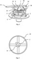
- the clamping jig 1 is formed by two basic parts, i.e. the hub 3 of the wheel 19 and the shaft sleeve 2. In combination, these two parts allow a simple mounting of the hub 3 of the wheel 19 on the shaft provided with the shaft sleeve 2 in question.
- the construction material of the hub 3 and the shaft sleeve 2 can be metal, preferably expanded, such as aluminium, but also other metals, plastics or combinations of metals and plastics or several metals.
- the hub 3 of the wheel 19 is centrally mounted and fixed in the rim or disc of the wheel 19 .
- the anchoring of the hub 3 can be made by means of wheel spokes, casting into a single element formed by a rim, the hub 3 and connecting spokes, or by another method well known to the person skilled in the field by fitting the hubs 3 in the wheels 19 .
- the hub 3 has a cylindrical body 17 with a lateral overlap formed by a projecting lever 11 .
- the shaft sleeve 2 is provided with a cavity used to anchor the shaft sleeve 2 to the shaft.
- the shaft sleeve 2 is provided with a locking groove 4 and, according to Figs. 1 , 2 , 4 and 6 , the hub 3 of the wheel 19 is provided with at least two pawls 5.
- the pawls 5 are pivotally arranged in the body 17 of the hub 3 . This arrangement allows roll movement of the pawls 5 between their two extreme positions. As shown in Figs.
- the hub 3 of the wheel 19 is further provided with a control mechanism 10 for controlling the movement of the pawls 5 between the extreme positions.
- the mechanism for moving the pawls 5 consists in that each pawl 5 in the hub 3 clamping position engages with its locking tooth 18 in the locking groove 4 of the shaft sleeve 2 and in the hub 3 release position the locking tooth 18 of the pawl 5 is pushed out of the locking groove 4 .
- the locking groove 4 is formed as a circular groove along the entire circumference of the shaft sleeve 2 and the inner profile of the locking groove 4 corresponds to the profile of the locking tooth 18 .
- each pawl 5 is formed in the shape of an "L" letter with two arms 20 , 21 .
- the anchor arm 2 0 is terminated at its free end by a locking tooth 18 .
- the control arm 21 the free end of which faces the centre of the hub 3 of the wheel 19 , engages with the control mechanism 10 .
- the pawl 5 is mounted in a semicircular groove 6 formed in the body 17 of the hub 3 of the wheel 19 .
- a semicircular projection 13 is formed on the pawl 5 at the point of contact of the anchor arm 20 and the control arm 21 . This semicircular projection 13 is complementary to the semicircular groove 6 and the pawl 5 is placed in this semicircular groove 6 by this semicircular projection 13 .
- the control mechanism 10 comprises an axially sliding shank 7 arranged in a circular hole of the body 1 7 of the hub 3 .
- the position of the sliding shank 7 corresponds to the mounting in the axis of the hub 3 of the wheel 19 .
- This sliding shank 7 is provided with a circular guide groove 8 at its one end into which the ends of the control arms 21 of the pawls 5 fit.
- the sliding shank 7 is provided with a through hole 9 .
- the sliding shank 7 is cylindrical in shape and the guide groove 8 is formed as a gap delimited by a pair of circumferential rings in the lower part of the sliding shank 7 .
- the through hole 9 is oval in shape and is arranged in the upper part of the sliding shank 7 . This shape allows the moving rod 12 to move in a biaxial system in the vertical plane of projection of the x- and y-axes of the orthogonal coordinate system.
- the control mechanism 10 is further formed by a lever 11 and a rod 12 .
- the rod 12 in question is hinged in the body 17 of the hub 3 of the wheel 19 at one end.
- the rod 12 is swivel-type connected to the lever 11 by means of a connecting pin 14 .
- the rod 12 is arranged so that at least one of its parts always passes through the through hole 9 of the sliding shank 7 .
- the lever 11 is formed in the shape of an "L" letter with one shorter and one longer arms.
- the shorter arm of the lever 11 is swivel-type connected to the rod 12 by means of a connecting pin 14 and its free end is provided with a shoulder 16 .
- This shoulder 16 slides on a sliding surface 15 which is formed in the body 17 of the hub 3 as a recess.
- the pawl 5 forms, in cross-section, the profile of the half-anchor, where the hook end is replaced by a locking tooth 18 .
- the control arm 21 is moved upwards and the pawl 5 is tilted by the anchor arm 20 with the locking tooth 18 out of the body 17 of the hub 3 when the sliding shank 7 is lifted and the pawls 5 thus acquire the function of the jaw clamps clamping the shaft sleeve 2 .
- the sliding movement of the sliding shank 7 is ensured by tilting the lever 11 . Tilting of the lever 11 causes a sliding movement of the rod 12 in the direction perpendicular to the axis of the wheel 19 and at the same time a lifting movement in the direction of the axis of the wheel 19 . As the rod 12 passes through the through hole 2 of the sliding shank 7 , its lifting then simultaneously lifts the entire sliding shank 7 .
- the lever 11 In order to prevent the pawls 5 from being released spontaneously from the clamp, the lever 11 is anchored in its lower extreme tilted position in the body 17 of the hub 3 of the wheel 19 . Release of the clamp and removal of the hub 3 from the shaft sleeve 2 is made by the opposite movement of the lever 11 to its upper extreme position.
- the anchoring of the shaft sleeve 2 to the shaft can be made in a detachable or non-detachable manner, by means of screws, by means of a respective clamping shape of the shaft and the inner cavity of the shaft sleeve 2 , by gluing or other method well known to the person skilled in the field for firm connection of circular components.
- the basic assembly of the hub 3 of the wheel 19 and the shaft sleeve 2 is ensured by the interlocking conical shape of the bearing surfaces of these elements, i.e. the conical surface of the hub 3 and the conical cavity of the shaft sleeve 2 .
- the pawls 5 and the locking groove 4 form only a retaining mechanism securing the connection of the hub 3 and the shaft sleeve 2 .
- the body 17 of the hub 3 of the wheel 19 and the shaft sleeve 2 can comprise various functional recesses aimed at reducing the mass and thus the weight or the resulting centrifugal force of the rotating clamping element 1 while maintaining the strength and safety parameters of the invention.
- the wheel clamping element designed for quick clamping of the wheel hub to the shaft or wheel axis finds industrial application mainly in the construction of non-motorized and low-speed motor carts, prams and other similar transport and transportation equipment.
Landscapes
- Engineering & Computer Science (AREA)
- Mechanical Engineering (AREA)
- Health & Medical Sciences (AREA)
- Life Sciences & Earth Sciences (AREA)
- Animal Behavior & Ethology (AREA)
- General Health & Medical Sciences (AREA)
- Public Health (AREA)
- Veterinary Medicine (AREA)
- Axle Suspensions And Sidecars For Cycles (AREA)
- Clamps And Clips (AREA)
Claims (6)
- Spannelement (1) zum Schnellspannen einer Nabe (3) eines Rades (19) auf einer Welle, wobei das Spannelement eine Wellenhülse (2) umfasst, die mit einer Sperrnut (4) versehen ist, und die Nabe (3) des Rades (19) mit mindestens zwei Sperrklinken (5) versehen ist, die schwenkbar in einem Körper (17) der Nabe (3) angeordnet sind, mit der Möglichkeit, die Sperrklinken (5) zwischen zwei Extrempositionen zu bewegen, und ferner die Nabe (3) des Rades (19) mit einem Steuermechanismus (10) zur Steuerung der Bewegung der Sperrklinken (5) zwischen diesen Extremstellungen ausgestattet ist, wobei jede Sperrklinke (5) in der Nabenspannstellung mit ihrem Sperrzahn (18) in die Sperrnut (4) der Wellenhülse (2) eingreift und in der Nabenfreigabestellung der Sperrzahn (18) der Sperrklinke (5) aus der Sperrnut (4) herausgedrückt wird, dadurch gekennzeichnet, dass jede Sperrklinke (5) in Form des Buchstabens "L" ausgebildet ist und aus einem Ankerarm (20) mit den Sperrzahn (18) und einem Steuerarm (21) besteht, dessen freies Ende der Mitte der Nabe (3) des Rades (19) zugewandt ist und in den Steuermechanismus (10) eingreift, während die Sperrklinke (5) in einer halbkreisförmigen Nut (6) am Berührungspunkt des Ankerarms (20) und des Steuerarms (21) gelagert ist.
- Spannelement nach Anspruch 1, dadurch gekennzeichnet, dass jede Sperrklinke (5) einen halbkreisförmigen Vorsprung (22) aufweist, der an der Berührungsstelle des Ankerarms (20) und des Steuerarms (21) komplementär zur halbkreisförmigen Nut (6) im Körper (17) der Nabe (3) ausgebildet ist.
- Spannelement nach Anspruch 1, dadurch gekennzeichnet, dass der Steuermechanismus (10) einen axial verschiebbaren Schaft (7) umfasst, wobei dieser Schaft (7) in einer kreisförmigen Bohrung des Körpers (17) der Nabe (3) in der Achse der Nabe (3) des Rades (19) angeordnet ist, und ferner dieser Schaft (7) an seinem einen Ende mit einer kreisförmigen Führungsnut (8) versehen ist, in die die Enden der Steuerarme (21) der Sperrklinken (5) passen, und der Schaft (7) an seinem anderen Ende mit einer Durchgangsbohrung (9) versehen ist.
- Spannelement nach Anspruch 3, dadurch gekennzeichnet, dass der Steuermechanismus (10) ferner einen Hebel (11) und eine Stange (12) des Hebels (11) umfasst, wobei ein Ende der Stange (12) des Hebels (11) im Körper (17) der Nabe (3) angelenkt ist und das andere Ende der Stange (12) des Hebels (11) mittels eines Verbindungsbolzens (14) schwenkbar mit dem Hebel (11) verbunden ist, wobei die Stange (12) des Hebels (11) die Durchgangsbohrung (9) des Gleitschafts (7) durchquert.
- Spannelement nach Anspruch 4, dadurch gekennzeichnet, dass der Hebel (11) L-förmig ausgebildet ist, wobei der kürzere Arm des Hebels (11) mittels eines Verbindungsbolzens (14) schwenkbar mit der Stange (12) verbunden ist und das freie Ende des kürzeren Arms des Hebels (11) mit einer Schulter (16) versehen ist, die entlang einer im Körper (17) der Nabe (3) ausgebildeten Gleitfläche (15) gleitet.
- Spannelement nach einem der Ansprüche 1 bis 5, dadurch gekennzeichnet, dass die Oberfläche der Nabe (3) und der Hohlraum der Wellenhülse (2) an der Stelle der gegenseitigen Berührung als formschlüssige Konusflächen angeordnet sind, um eine schnellere und genauere Montage dieser Elemente zu ermöglichen.
Applications Claiming Priority (1)
| Application Number | Priority Date | Filing Date | Title |
|---|---|---|---|
| CZ2020-37358U CZ35095U1 (cs) | 2020-03-23 | 2020-03-23 | Upínací prvek |
Publications (2)
| Publication Number | Publication Date |
|---|---|
| EP3884918A1 EP3884918A1 (de) | 2021-09-29 |
| EP3884918B1 true EP3884918B1 (de) | 2023-08-30 |
Family
ID=76088896
Family Applications (1)
| Application Number | Title | Priority Date | Filing Date |
|---|---|---|---|
| EP20186172.1A Active EP3884918B1 (de) | 2020-03-23 | 2020-07-16 | Klemmelement |
Country Status (2)
| Country | Link |
|---|---|
| EP (1) | EP3884918B1 (de) |
| CZ (1) | CZ35095U1 (de) |
Family Cites Families (5)
| Publication number | Priority date | Publication date | Assignee | Title |
|---|---|---|---|---|
| DE4429153A1 (de) * | 1994-08-17 | 1996-02-22 | Alber Ulrich Gmbh | Kleinfahrzeug mit mindestens einem Antriebslaufrad mit Nabenmotor |
| DE19513764A1 (de) | 1995-04-11 | 1996-10-17 | Thomas Ripa | Schnellwechselachse für Radnabenlagerung einspuriger Fahrzeuge |
| US5957544A (en) | 1998-05-22 | 1999-09-28 | Hu; Stephen | Wheel fixing device for a baby stroller |
| FR3001887B1 (fr) * | 2013-02-08 | 2015-02-13 | Institution Nationale Des Invalides Ct D Etudes Et De Rech Sur L App Des Handicapes | Systeme de montage d'une roue sur un fauteuil roulant |
| FR3011511B1 (fr) * | 2013-10-09 | 2016-12-30 | Assist Publique - Hopitaux De Paris | Dispositif universel de solidarisation reversible a un chassis d'une roue amovible |
-
2020
- 2020-03-23 CZ CZ2020-37358U patent/CZ35095U1/cs active Protection Beyond IP Right Term
- 2020-07-16 EP EP20186172.1A patent/EP3884918B1/de active Active
Also Published As
| Publication number | Publication date |
|---|---|
| EP3884918A1 (de) | 2021-09-29 |
| CZ35095U1 (cs) | 2021-05-25 |
Similar Documents
| Publication | Publication Date | Title |
|---|---|---|
| US8424975B2 (en) | Bicycle wheel securing structure | |
| US7654546B2 (en) | Bicycle wheel securing structure | |
| US9944119B2 (en) | Hub assembly for a bicycle | |
| US7556321B2 (en) | Bicycle wheel securing structure | |
| USRE45684E1 (en) | Apparatus for twist-to-lock retention of a wheel | |
| US8186768B2 (en) | Quick release, especially for bicycles | |
| US9616963B2 (en) | Quick release device | |
| US9199689B2 (en) | Wheel axle assembly | |
| US9376160B2 (en) | Axle assembly | |
| CN210255019U (zh) | 一种拧紧机构及车轮拧紧系统 | |
| JP2013529152A (ja) | 中実車軸用の調整可能な自転車用クイックリリース | |
| US8783790B2 (en) | Axle system for a two-wheeled vehicle | |
| US6976791B2 (en) | Bearing apparatus for a bicycle hub | |
| EP3884918A1 (de) | Klemmelement | |
| US20240227981A1 (en) | Wheel hub | |
| TW201730039A (zh) | 快拆裝置 | |
| US8888196B2 (en) | Field spoke repair kit | |
| US4289418A (en) | Device for securing an expandable hub in a hole | |
| CA2385286A1 (en) | Bicycle freewheel hub supported on a central drive cylinder | |
| EP3497004B1 (de) | Sitzklemme zum klemmen eines sitzrohres | |
| CA2507364A1 (en) | Quick fastening wheel weight system | |
| JP4047881B2 (ja) | 単軸手動締付装置 | |
| CN219617520U (zh) | 用于风力发电机组偏航卡钳的力矩工装 | |
| SU1691141A1 (ru) | Ступица спицевого колеса | |
| US20150203167A1 (en) | Front Axle Retention for an Electric Cycle |
Legal Events
| Date | Code | Title | Description |
|---|---|---|---|
| PUAI | Public reference made under article 153(3) epc to a published international application that has entered the european phase |
Free format text: ORIGINAL CODE: 0009012 |
|
| STAA | Information on the status of an ep patent application or granted ep patent |
Free format text: STATUS: THE APPLICATION HAS BEEN PUBLISHED |
|
| AK | Designated contracting states |
Kind code of ref document: A1 Designated state(s): AL AT BE BG CH CY CZ DE DK EE ES FI FR GB GR HR HU IE IS IT LI LT LU LV MC MK MT NL NO PL PT RO RS SE SI SK SM TR |
|
| STAA | Information on the status of an ep patent application or granted ep patent |
Free format text: STATUS: REQUEST FOR EXAMINATION WAS MADE |
|
| 17P | Request for examination filed |
Effective date: 20220328 |
|
| RBV | Designated contracting states (corrected) |
Designated state(s): AL AT BE BG CH CY CZ DE DK EE ES FI FR GB GR HR HU IE IS IT LI LT LU LV MC MK MT NL NO PL PT RO RS SE SI SK SM TR |
|
| RIC1 | Information provided on ipc code assigned before grant |
Ipc: A61G 5/10 20060101AFI20230130BHEP |
|
| GRAP | Despatch of communication of intention to grant a patent |
Free format text: ORIGINAL CODE: EPIDOSNIGR1 |
|
| STAA | Information on the status of an ep patent application or granted ep patent |
Free format text: STATUS: GRANT OF PATENT IS INTENDED |
|
| INTG | Intention to grant announced |
Effective date: 20230323 |
|
| GRAS | Grant fee paid |
Free format text: ORIGINAL CODE: EPIDOSNIGR3 |
|
| GRAA | (expected) grant |
Free format text: ORIGINAL CODE: 0009210 |
|
| STAA | Information on the status of an ep patent application or granted ep patent |
Free format text: STATUS: THE PATENT HAS BEEN GRANTED |
|
| AK | Designated contracting states |
Kind code of ref document: B1 Designated state(s): AL AT BE BG CH CY CZ DE DK EE ES FI FR GB GR HR HU IE IS IT LI LT LU LV MC MK MT NL NO PL PT RO RS SE SI SK SM TR |
|
| REG | Reference to a national code |
Ref country code: GB Ref legal event code: FG4D |
|
| REG | Reference to a national code |
Ref country code: CH Ref legal event code: EP |
|
| REG | Reference to a national code |
Ref country code: DE Ref legal event code: R096 Ref document number: 602020016552 Country of ref document: DE |
|
| REG | Reference to a national code |
Ref country code: IE Ref legal event code: FG4D |
|
| REG | Reference to a national code |
Ref country code: LT Ref legal event code: MG9D |
|
| REG | Reference to a national code |
Ref country code: NL Ref legal event code: MP Effective date: 20230830 |
|
| REG | Reference to a national code |
Ref country code: AT Ref legal event code: MK05 Ref document number: 1604475 Country of ref document: AT Kind code of ref document: T Effective date: 20230830 |
|
| PG25 | Lapsed in a contracting state [announced via postgrant information from national office to epo] |
Ref country code: GR Free format text: LAPSE BECAUSE OF FAILURE TO SUBMIT A TRANSLATION OF THE DESCRIPTION OR TO PAY THE FEE WITHIN THE PRESCRIBED TIME-LIMIT Effective date: 20231201 |
|
| PG25 | Lapsed in a contracting state [announced via postgrant information from national office to epo] |
Ref country code: IS Free format text: LAPSE BECAUSE OF FAILURE TO SUBMIT A TRANSLATION OF THE DESCRIPTION OR TO PAY THE FEE WITHIN THE PRESCRIBED TIME-LIMIT Effective date: 20231230 |
|
| PG25 | Lapsed in a contracting state [announced via postgrant information from national office to epo] |
Ref country code: SE Free format text: LAPSE BECAUSE OF FAILURE TO SUBMIT A TRANSLATION OF THE DESCRIPTION OR TO PAY THE FEE WITHIN THE PRESCRIBED TIME-LIMIT Effective date: 20230830 Ref country code: RS Free format text: LAPSE BECAUSE OF FAILURE TO SUBMIT A TRANSLATION OF THE DESCRIPTION OR TO PAY THE FEE WITHIN THE PRESCRIBED TIME-LIMIT Effective date: 20230830 Ref country code: NO Free format text: LAPSE BECAUSE OF FAILURE TO SUBMIT A TRANSLATION OF THE DESCRIPTION OR TO PAY THE FEE WITHIN THE PRESCRIBED TIME-LIMIT Effective date: 20231130 Ref country code: LV Free format text: LAPSE BECAUSE OF FAILURE TO SUBMIT A TRANSLATION OF THE DESCRIPTION OR TO PAY THE FEE WITHIN THE PRESCRIBED TIME-LIMIT Effective date: 20230830 Ref country code: LT Free format text: LAPSE BECAUSE OF FAILURE TO SUBMIT A TRANSLATION OF THE DESCRIPTION OR TO PAY THE FEE WITHIN THE PRESCRIBED TIME-LIMIT Effective date: 20230830 Ref country code: IS Free format text: LAPSE BECAUSE OF FAILURE TO SUBMIT A TRANSLATION OF THE DESCRIPTION OR TO PAY THE FEE WITHIN THE PRESCRIBED TIME-LIMIT Effective date: 20231230 Ref country code: HR Free format text: LAPSE BECAUSE OF FAILURE TO SUBMIT A TRANSLATION OF THE DESCRIPTION OR TO PAY THE FEE WITHIN THE PRESCRIBED TIME-LIMIT Effective date: 20230830 Ref country code: GR Free format text: LAPSE BECAUSE OF FAILURE TO SUBMIT A TRANSLATION OF THE DESCRIPTION OR TO PAY THE FEE WITHIN THE PRESCRIBED TIME-LIMIT Effective date: 20231201 Ref country code: FI Free format text: LAPSE BECAUSE OF FAILURE TO SUBMIT A TRANSLATION OF THE DESCRIPTION OR TO PAY THE FEE WITHIN THE PRESCRIBED TIME-LIMIT Effective date: 20230830 Ref country code: AT Free format text: LAPSE BECAUSE OF FAILURE TO SUBMIT A TRANSLATION OF THE DESCRIPTION OR TO PAY THE FEE WITHIN THE PRESCRIBED TIME-LIMIT Effective date: 20230830 |
|
| PG25 | Lapsed in a contracting state [announced via postgrant information from national office to epo] |
Ref country code: PL Free format text: LAPSE BECAUSE OF FAILURE TO SUBMIT A TRANSLATION OF THE DESCRIPTION OR TO PAY THE FEE WITHIN THE PRESCRIBED TIME-LIMIT Effective date: 20230830 Ref country code: NL Free format text: LAPSE BECAUSE OF FAILURE TO SUBMIT A TRANSLATION OF THE DESCRIPTION OR TO PAY THE FEE WITHIN THE PRESCRIBED TIME-LIMIT Effective date: 20230830 |
|
| PG25 | Lapsed in a contracting state [announced via postgrant information from national office to epo] |
Ref country code: ES Free format text: LAPSE BECAUSE OF FAILURE TO SUBMIT A TRANSLATION OF THE DESCRIPTION OR TO PAY THE FEE WITHIN THE PRESCRIBED TIME-LIMIT Effective date: 20230830 |
|
| PG25 | Lapsed in a contracting state [announced via postgrant information from national office to epo] |
Ref country code: SM Free format text: LAPSE BECAUSE OF FAILURE TO SUBMIT A TRANSLATION OF THE DESCRIPTION OR TO PAY THE FEE WITHIN THE PRESCRIBED TIME-LIMIT Effective date: 20230830 Ref country code: RO Free format text: LAPSE BECAUSE OF FAILURE TO SUBMIT A TRANSLATION OF THE DESCRIPTION OR TO PAY THE FEE WITHIN THE PRESCRIBED TIME-LIMIT Effective date: 20230830 Ref country code: ES Free format text: LAPSE BECAUSE OF FAILURE TO SUBMIT A TRANSLATION OF THE DESCRIPTION OR TO PAY THE FEE WITHIN THE PRESCRIBED TIME-LIMIT Effective date: 20230830 Ref country code: EE Free format text: LAPSE BECAUSE OF FAILURE TO SUBMIT A TRANSLATION OF THE DESCRIPTION OR TO PAY THE FEE WITHIN THE PRESCRIBED TIME-LIMIT Effective date: 20230830 Ref country code: DK Free format text: LAPSE BECAUSE OF FAILURE TO SUBMIT A TRANSLATION OF THE DESCRIPTION OR TO PAY THE FEE WITHIN THE PRESCRIBED TIME-LIMIT Effective date: 20230830 Ref country code: SK Free format text: LAPSE BECAUSE OF FAILURE TO SUBMIT A TRANSLATION OF THE DESCRIPTION OR TO PAY THE FEE WITHIN THE PRESCRIBED TIME-LIMIT Effective date: 20230830 Ref country code: PT Free format text: LAPSE BECAUSE OF FAILURE TO SUBMIT A TRANSLATION OF THE DESCRIPTION OR TO PAY THE FEE WITHIN THE PRESCRIBED TIME-LIMIT Effective date: 20240102 |
|
| PG25 | Lapsed in a contracting state [announced via postgrant information from national office to epo] |
Ref country code: IT Free format text: LAPSE BECAUSE OF FAILURE TO SUBMIT A TRANSLATION OF THE DESCRIPTION OR TO PAY THE FEE WITHIN THE PRESCRIBED TIME-LIMIT Effective date: 20230830 |
|
| REG | Reference to a national code |
Ref country code: DE Ref legal event code: R097 Ref document number: 602020016552 Country of ref document: DE |
|
| PLBE | No opposition filed within time limit |
Free format text: ORIGINAL CODE: 0009261 |
|
| STAA | Information on the status of an ep patent application or granted ep patent |
Free format text: STATUS: NO OPPOSITION FILED WITHIN TIME LIMIT |
|
| PG25 | Lapsed in a contracting state [announced via postgrant information from national office to epo] |
Ref country code: SI Free format text: LAPSE BECAUSE OF FAILURE TO SUBMIT A TRANSLATION OF THE DESCRIPTION OR TO PAY THE FEE WITHIN THE PRESCRIBED TIME-LIMIT Effective date: 20230830 |
|
| 26N | No opposition filed |
Effective date: 20240603 |
|
| PG25 | Lapsed in a contracting state [announced via postgrant information from national office to epo] |
Ref country code: BG Free format text: LAPSE BECAUSE OF FAILURE TO SUBMIT A TRANSLATION OF THE DESCRIPTION OR TO PAY THE FEE WITHIN THE PRESCRIBED TIME-LIMIT Effective date: 20230830 |
|
| PG25 | Lapsed in a contracting state [announced via postgrant information from national office to epo] |
Ref country code: BG Free format text: LAPSE BECAUSE OF FAILURE TO SUBMIT A TRANSLATION OF THE DESCRIPTION OR TO PAY THE FEE WITHIN THE PRESCRIBED TIME-LIMIT Effective date: 20230830 |
|
| PG25 | Lapsed in a contracting state [announced via postgrant information from national office to epo] |
Ref country code: MC Free format text: LAPSE BECAUSE OF FAILURE TO SUBMIT A TRANSLATION OF THE DESCRIPTION OR TO PAY THE FEE WITHIN THE PRESCRIBED TIME-LIMIT Effective date: 20230830 |
|
| REG | Reference to a national code |
Ref country code: CH Ref legal event code: PL |
|
| PG25 | Lapsed in a contracting state [announced via postgrant information from national office to epo] |
Ref country code: LU Free format text: LAPSE BECAUSE OF NON-PAYMENT OF DUE FEES Effective date: 20240716 |
|
| PG25 | Lapsed in a contracting state [announced via postgrant information from national office to epo] |
Ref country code: LU Free format text: LAPSE BECAUSE OF NON-PAYMENT OF DUE FEES Effective date: 20240716 |
|
| PG25 | Lapsed in a contracting state [announced via postgrant information from national office to epo] |
Ref country code: CH Free format text: LAPSE BECAUSE OF NON-PAYMENT OF DUE FEES Effective date: 20240731 Ref country code: BE Free format text: LAPSE BECAUSE OF NON-PAYMENT OF DUE FEES Effective date: 20240731 |
|
| REG | Reference to a national code |
Ref country code: BE Ref legal event code: MM Effective date: 20240731 |
|
| PGFP | Annual fee paid to national office [announced via postgrant information from national office to epo] |
Ref country code: GB Payment date: 20250611 Year of fee payment: 6 |
|
| PGFP | Annual fee paid to national office [announced via postgrant information from national office to epo] |
Ref country code: FR Payment date: 20250611 Year of fee payment: 6 |
|
| PGFP | Annual fee paid to national office [announced via postgrant information from national office to epo] |
Ref country code: CZ Payment date: 20250611 Year of fee payment: 6 |
|
| PG25 | Lapsed in a contracting state [announced via postgrant information from national office to epo] |
Ref country code: IE Free format text: LAPSE BECAUSE OF NON-PAYMENT OF DUE FEES Effective date: 20240716 |
|
| PGFP | Annual fee paid to national office [announced via postgrant information from national office to epo] |
Ref country code: DE Payment date: 20250612 Year of fee payment: 6 |
|
| PG25 | Lapsed in a contracting state [announced via postgrant information from national office to epo] |
Ref country code: CY Free format text: LAPSE BECAUSE OF FAILURE TO SUBMIT A TRANSLATION OF THE DESCRIPTION OR TO PAY THE FEE WITHIN THE PRESCRIBED TIME-LIMIT; INVALID AB INITIO Effective date: 20200716 |
|
| PG25 | Lapsed in a contracting state [announced via postgrant information from national office to epo] |
Ref country code: HU Free format text: LAPSE BECAUSE OF FAILURE TO SUBMIT A TRANSLATION OF THE DESCRIPTION OR TO PAY THE FEE WITHIN THE PRESCRIBED TIME-LIMIT; INVALID AB INITIO Effective date: 20200716 |