EP3497004B1 - Sitzklemme zum klemmen eines sitzrohres - Google Patents
Sitzklemme zum klemmen eines sitzrohres Download PDFInfo
- Publication number
- EP3497004B1 EP3497004B1 EP17752469.1A EP17752469A EP3497004B1 EP 3497004 B1 EP3497004 B1 EP 3497004B1 EP 17752469 A EP17752469 A EP 17752469A EP 3497004 B1 EP3497004 B1 EP 3497004B1
- Authority
- EP
- European Patent Office
- Prior art keywords
- seat
- lever
- clamp
- ring
- collar
- Prior art date
- Legal status (The legal status is an assumption and is not a legal conclusion. Google has not performed a legal analysis and makes no representation as to the accuracy of the status listed.)
- Active
Links
Images


Classifications
-
- B—PERFORMING OPERATIONS; TRANSPORTING
- B62—LAND VEHICLES FOR TRAVELLING OTHERWISE THAN ON RAILS
- B62K—CYCLES; CYCLE FRAMES; CYCLE STEERING DEVICES; RIDER-OPERATED TERMINAL CONTROLS SPECIALLY ADAPTED FOR CYCLES; CYCLE AXLE SUSPENSIONS; CYCLE SIDECARS, FORECARS, OR THE LIKE
- B62K19/00—Cycle frames
- B62K19/30—Frame parts shaped to receive other cycle parts or accessories
- B62K19/36—Frame parts shaped to receive other cycle parts or accessories for attaching saddle pillars, e.g. adjustable during ride
Definitions
- the present invention relates to a bicycle seat clamp or tricycle seat clamp to clamp a seat tube.
- Adjustable seat supports allow a bicycle to be made and sold with standard component parts, and then adjusted by the end user. This is particularly useful when the bicycle has more than one user, for example in the case of re-sale, hire or rental. This is also useful if the bicycle is only used by a single user who wants to adjust their seat height due to a change in preference or situation. When a child grows, for example, the seat can be raised.
- a known quick release seat support for a bicycle comprises a seat post in the form of a circular tube that can be inserted into a circular cross section seat tube which is part of the bicycle frame.
- the end of the seat tube has a slit, and is surrounded by a clamp in the form of a split collar, with a bolt through the ends of the collar. Tightening of the bolt draws the ends of the collar closer together to reduce the diameter of the collar and hence reduce the diameter of the seat tube by partial closing of the slit, to thereby clamp the seat post in position in the seat tube.
- a known quick release seat clamp is used to clamp bicycle seat posts to bicycle seat tubes, so that the user can adjust the height of the seat quickly and without the need for tools.
- the known quick release seat clamp includes a lever, a single cam and pivot, and a split collar which fits around the seat post and tube.
- the cam mechanism is used to reduce the radius of the collar until the seat post is fixed to the seat tube. This can be done by manually moving the lever to rotate the cam mechanism and tighten the grip of the collar.
- a screw mechanism can be used to adjust the radius of the collar, and the cam mechanism is then used to further reduce the radius of the collar until the seat post is fixed to the seat tube.
- This problem is amplified when the user is attempting to adjust the height of the seat and seat post quickly. This problem is also amplified in hire or rental bicycles where the user does not have a specific incentive to maintain the appearance of the bicycle.
- a bicycle seat clamp or tricycle seat clamp to clamp a seat tube which receives a seat post in order to hold the seat post in position in the seat tube
- the seat clamp comprising a split collar to surround the seat tube, the split collar having a single split, the split being defined between two ends
- the seat clamp further comprising a cam mechanism acting on the said ends and a lever to be operated by a user to operate the cam mechanism and thereby tighten the split collar
- the lever being pivotally connected to the split collar through the cam mechanism and also being connected to the split collar through a simple pivot connection spaced from the split such that the direction of travel of the lever has a major component along the axis of the split collar.
- the invention has the advantage of preventing wear and tear on the bike associated with rotation of the lever.
- the use of a simple pivot connection means that the objective of constraining movement of the lever can be achieved simply and at low cost.
- the movement of the lever may be constrained such that the axis of the split collar/seat tube lies in the plane of movement of the lever.
- the lever may be longer than the diameter of the split collar. This has the advantage that the user can open and close (clamp) the clamp more easily, as they have greater leverage, which reduces the force required.
- the lever may conveniently be Y-shaped. This provides a slim handle for convenient gripping by the user, and also is economical in use of material.
- the lever may be symmetrical.
- the cam mechanism may be of any suitable type and may be an eccentric cam.
- the cam mechanism may comprise a first ring on the lever and a journal on which the first ring pivots, the outer surface of the first ring constituting a cam surface.
- the first ring may be an eccentric cam.
- the journal of the cam mechanism may be connected to a bolt which passes through bores in the end of the split collar.
- the first ring comprises two sub-rings side by side and the journal is received in both sub-rings and a bolt is attached to the journal between the sub-rings. In this way the force through the bolt to close the ends of the split collar is central and divided between the two sub-rings.
- the simple pivot connection may comprise a second ring on the lever, and a journal on which the second ring pivots, the second ring being of constant thickness.
- the second ring comprises two sub-rings side by side and the journal is received in both sub-rings, and a bolt is attached to the journal between the sub-rings.
- the lever is preferably substantially symmetrical and may be symmetrical except for the first and second rings.
- the pivot connections may be on opposite sides of the split collar.
- the split collar may include a tab opposite the split and the lever may be pivotally connected to the tab through the simple pivot connection.
- a seat clamp to clamp a seat tube which receives a seat post in order to hold the seat post in position in the seat tube
- the seat clamp comprising a split collar to surround the seat tube and a lever to be operated by a user to tighten the split collar, wherein the lever is pivotally connected in two places on the same side of the split in order to constrain movement of the lever such that the direction of travel of the lever has a major component along the axis of the seat tube.
- the invention has the advantage of preventing wear and tear on the bike associated with rotation of the lever.
- the movement of the lever may be constrained such that the axis of the seat tube lies in the plane of movement of the lever.
- the lever may be longer than the diameter of the clamping means. This has the advantage that the user can open and close (clamp) the clamp more easily, as they have greater leverage, which reduces the force required.
- the lever may conveniently be Y-shaped.
- the lever may be symmetrical.
- At least one pivot connection may include a cam mechanism to clamp the clamping means.
- the cam mechanism may be of any suitable type and may be an eccentric cam.
- the clamping means may comprise a split collar and the cam mechanism may be arranged to bring the ends of the collar closer together to reduce the diameter of the collar.
- the seat clamp may be a bicycle or tricycle seat clamp.
- the split collar has a single split.
- FIG. 1 shows a seat clamp 1 in an embodiment of the invention.
- the seat clamp 1 comprises a collar 10, a cam mechanism 20 and a lever 30.
- the collar 10 comprises the aforesaid "clamping means”.
- the collar 10 is a split collar.
- the collar 10 defines a substantially circular opening 11 which defines a notional axis A, as shown in Fig 1 .
- the collar 10 comprises a split collar main body 16, a split opening 18 and three tabs: one fixed tab 12 and two adjustable tabs 14.
- the fixed tab 12 has a larger dimension in a circumferential direction around the collar main body 16 than each adjustable tab 14.
- the split collar main body 16, and the three tabs 12, 14, are a single unitary piece.
- the tabs 12, 14, extend from the main body 16 away from the axis A.
- the two adjustable tabs 14 are on the opposite side of the main body 16 to the fixed tab 12.
- the two adjustable tabs 14 are on opposite sides of the split opening 18 to each other.
- the adjustable tabs 14 are adapted to be moved in a circumferential direction towards or away from each other. Movement of the adjustable tabs 14 away from each other causes enlargement of the circular opening 11. Movement of the adjustable tabs 14 towards each other causes a reduction in the size of the circular opening 11.
- the cam mechanism 20 comprises a ring 22, a cam ring 24, a ring bar 26 and a cam ring bar 27.
- the ring bar 26 is best seen in Figure 2 .
- the ring 22 is substantially circular.
- the ring 22 comprises two sub-rings. The two sub-rings are substantially the same and fixedly attached to each other side by side.
- the ring bar 26 has a cylindrical outer surface and is adapted to fit inside the ring 22.
- the cam ring 24 comprises two cam sub-rings, each cam sub-ring having an enlarged circumferential section on one side. Each cam sub-ring is thus an eccentric cam.
- the eccentric cam defines two circles which are not concentric; an outer circle and an inner circle, The inner circle is adapted to receive the cam ring bar 27.
- the two cam sub-rings are substantially the same and fixedly attached to each other side by side.
- the enlarged circumferential section of each cam ring is on an opposite side of the cam sub-rings (though not directly opposite) to where the cam sub-rings are attached to each other.
- the cam ring bar 27 has a cylindrical outer surface and is adapted to fit inside the cam ring 24.
- the rings 22, 24 and bars 26 comprise the aforesaid "pivot connections".
- the lever 30 comprises a handle 32 and a U-shaped bridge 36.
- the handle 32 and the U-shaped bridge 36 of the lever 30 define a Y-shape.
- the lever 30 is symmetrical.
- the handle 32 is longer than the diameter of the collar 10.
- the handle 32 has a first end 33 and a second end 34.
- the handle 32 has a central stem 35, a larger portion than the stem 35 at its first end 33, and terminates in a larger portion than the stem 35 at its second end 34.
- the handle 32 is thus designed ergonomically.
- the U-shaped bridge 36 has a similar cross-sectional dimension to the handle 32.
- the U-shaped bridge 36 is substantially symmetrical.
- the handle 32 is aligned with and attached to the outside of the U-shaped bridge 36, such that the handle 32 defines an axis about which the U-shaped bridge is symmetrical.
- the ring 22 of the cam mechanism 20 is integral with the end of one arm of the bridge 36, and the cam ring 24 of the cam mechanism 20 is integral with the end of the other arm of the bridge 36.
- the ring 22 and the cam ring 24 of the cam mechanism 20, and the handle 32 and U-shaped bridge 36 of the lever 30 are together a single unitary piece.
- the collar 10 is attached to the ring 22 and the cam ring 24 via the ring bar 26 and the cam ring bar 27 respectively.
- a bolt 50 is received in a bore 52 through the fixed tab 12 of the collar 10.
- the head 54 of the bolt 50 engages the rear of the fixed tab 12, while the threaded end 56 passes in turn through a dished washer 58 and a bush 60, then between the sub rings 22' and into a radial threaded bore 62 in the ring bar 26.
- the bush 60 has a curved surface 64 to contact and complement the outer surfaces of the sub rings 22'.
- the adjuster nut 74 of the cam bolt 70 is enlarged and includes grooves 90 for grip.
- the shaft 76 of the cam bolt 70 passes through bores 72 in the adjustable tabs 14.
- the handle 32, U-shaped bridge 36, ring 22 and cam ring 24 are together adapted to pivot in a direction with a major component parallel to the axis A. Both the ring 22 and the cam ring 24 act as pivot points, so that movement of the lever 30 is constrained. This means that the lever 30 can only move in a plane in which the axis A of the collar 10 lies.
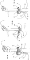
- Figures 3a, 3b and 3c show the seat clamp in three stages of use. In order to adjust the height of the seat, a user follows the steps outlined below in stages 1 to 3.
- Figure 3a shows the seat clamp 1 in a closed (clamped position), clamped to a seat tube 4.
- a seat post 3 is received in the seat tube 4.
- the seat post 3 has a fixture 5 at the top to mount a saddle (not shown).
- the opening 11 of the collar 10 is adjusted to such a diameter that the seat clamp 1 clamps and grips the seat tube 4.
- the seat tube 4 includes a slit 6, so that when the seat clamp 1 is clamped, the diameter of the top of the seat tube 4 can be reduced to grip the seat post 3. In this position, the seat post 3 and seat tube 4 are fixed in place relative to each other by the seat clamp 1.
- Enlargement of the opening 11 reduces and removes the clamping force of the seat clamp 1, and allows movement of the seat post 3 relative to the seat tube 4 in direction along the axis A.
- the seat and seat post 3 can be moved to the preferred height, as shown in Figure 3b .
- the user In order to fix the seat and seat post 3 in place at the preferred height, the user must pivot the lever 30 about the pivot points in a second direction (the second direction being the opposite direction to the first direction), rotating the lever 30 so that the second end 34 of the handle 32 is further away from the seat.
- the movement of the lever 30 is constrained because, unlike the prior known lever described above, it is connected to the collar 10 at two positions through the rings 22, 24. Hence it can only move up and down, and cannot be used like a wing nut, with the consequent risk of damage to adjacent surfaces of the bicycle or tricycle. Also, while the prior lever is no longer than the diameter of the seat tube, so that it does not stick out when the cycle is in use, the lever 32 of the embodiment can be longer, as it lies down the back of the seat tube 4 when clamped and cannot be pivotted sideways to get in the way of the rider. Indeed the length of the lever 30 in the embodiment, from the rings 22, 24, to the free end 34 of the handle 32 is 105mm, which is 3.3 times the diameter of the seat post 3.
- All of the parts of the seat clamp 1 may be made from steel or aluminium or any other suitable material with the exception of the bushes 60, which may be made from a suitable low friction plastics material such as nylon.
- the cam need not be an eccentric cam, the cam surface could be non-circular. Also, as the movement of the lever is only ever about 120° the cam surface could be just over a 120° arc of the cam ring 24.
Landscapes
- Engineering & Computer Science (AREA)
- Mechanical Engineering (AREA)
- Clamps And Clips (AREA)
Claims (14)
- Fahrradsitzklemme oder Dreiradsitzklemme zum Festklemmen eines Sattelrohrs, das eine Sattelstütze aufnimmt, um die Sattelstütze in Position im Sattelrohr zu halten, wobei die Sitzklemme eine geteilte Manschette (10) aufweist, um das Sattelrohr zu umgeben, wobei die geteilte Manschette (10) eine einzige Teilung (18) aufweist, die Teilung (18) zwischen zwei Enden (14) definiert ist, wobei die Sitzklemme ferner einen auf die Enden (14) einwirkenden Nockenmechanismus (20) und einen Hebel (30) aufweist, der von einem Benutzer betätigt wird, um den Nockenmechanismus (20) zu betätigen und dadurch die geteilte Manschette (10) festzuziehen, wobei der Hebel (30) schwenkbar über den Nockenmechanismus (20) mit der geteilten Manschette (10) verbunden ist, dadurch gekennzeichnet, so dass der Hebel auch mit der geteilten Manschette (10) über eine einfache Schwenkverbindung (20) verbunden ist, die von der Teilung (18) beabstandet ist, dass die Bewegungsrichtung des Hebels (30) eine Hauptkomponente entlang der Achse der geteilten Manschette (10) aufweist.
- Sitzklemme nach Anspruch 1, wobei der Nockenmechanismus (20) einen ersten Ring (24) am Hebel (30) und einen Zapfen (27) umfasst, um dem der erste Ring (24) schwenkt, wobei die Außenfläche des ersten Rings (24) eine Nockenfläche bildet.
- Sitzklemme nach Anspruch 2, wobei der Zapfen (27) des Nockenmechanismus (20) mit einem Bolzen (70) verbunden ist, der durch Bohrungen (72) in den Enden (14) der geteilten Manschette (10) verläuft.
- Sitzklemme nach Anspruch 3, wobei der erste Ring (24) zwei Teilringe nebeneinander umfasst, und der Zapfen (27) in beiden Teilringen aufgenommen ist, und der Bolzen (70) zwischen den Teilringen am Zapfen (27) angebracht ist.
- Sitzklemme nach einem der vorhergehenden Ansprüche, wobei die einfache Schwenkverbindung einen zweiten Ring (22) am Hebel (30) und einen Zapfen (26) umfasst, um den der zweite Ring (22) schwenkt, wobei der zweite Ring (22) eine konstante Dicke aufweist.
- Sitzklemme nach Anspruch 5, wobei der zweite Ring (22) zwei Teilringe (22') nebeneinander aufweist, und der Zapfen (26) in beiden Teilringen (22') aufgenommen ist, und ein Bolzen (50) an dem Zapfen (26) zwischen den Teilringen (22') angebracht ist.
- Sitzklemme nach Anspruch 5 oder Anspruch 6, wenn abhängig von Anspruch 2, 3 oder 4, wobei der Hebel (30) mit Ausnahme der Ringe (22, 24) symmetrisch ist.
- Sitzklemme nach einem der vorhergehenden Ansprüche, wobei sich die Schwenkverbindungen auf gegenüberliegenden Seiten der geteilten Manschette (10) befinden.
- Sitzklemme nach einem der vorhergehenden Ansprüche, wobei die geteilte Manschette (10) eine Lasche (12) gegenüber der Teilung (18) umfasst, und der Hebel (30) über die einfache Schwenkverbindung schwenkbar mit der Lasche (12) verbunden ist.
- Sitzklemme nach einem der vorhergehenden Ansprüche, wobei die Bewegung des Hebels (30) derart eingeschränkt ist, dass die Achse der geteilten Manschette (10) in der Bewegungsebene des Hebels (30) liegt.
- Sitzklemme nach einem der vorhergehenden Ansprüche, wobei der Hebel (30) länger als der Durchmesser der geteilten Manschette (10) ist.
- Sitzklemme nach Anspruch 11, wobei der Hebel (30) mehr als doppelt so lang ist wie der Durchmesser der geteilten Manschette (10).
- Sitzklemme nach Anspruch 11, wobei der Hebel (30) mehr als dreimal so lang ist wie der Durchmesser der geteilten Manschette (10).
- Sitzklemme nach einem der vorhergehenden Ansprüche, wobei der Hebel (30) Y-förmig ist.
Applications Claiming Priority (2)
| Application Number | Priority Date | Filing Date | Title |
|---|---|---|---|
| GBGB1613787.9A GB201613787D0 (en) | 2016-08-11 | 2016-08-11 | A seat clamp to clamp a seat tube |
| PCT/GB2017/052379 WO2018029491A1 (en) | 2016-08-11 | 2017-08-11 | A seat clamp to clamp a seat tube |
Publications (2)
| Publication Number | Publication Date |
|---|---|
| EP3497004A1 EP3497004A1 (de) | 2019-06-19 |
| EP3497004B1 true EP3497004B1 (de) | 2020-12-02 |
Family
ID=56985894
Family Applications (1)
| Application Number | Title | Priority Date | Filing Date |
|---|---|---|---|
| EP17752469.1A Active EP3497004B1 (de) | 2016-08-11 | 2017-08-11 | Sitzklemme zum klemmen eines sitzrohres |
Country Status (3)
| Country | Link |
|---|---|
| EP (1) | EP3497004B1 (de) |
| GB (2) | GB201613787D0 (de) |
| WO (1) | WO2018029491A1 (de) |
Families Citing this family (2)
| Publication number | Priority date | Publication date | Assignee | Title |
|---|---|---|---|---|
| CN108189939B (zh) * | 2018-02-08 | 2023-06-23 | 昆山华特机械科技有限公司 | 自行车用升降座管 |
| US11602665B2 (en) * | 2020-09-06 | 2023-03-14 | Peloton Interactive, Inc. | Seat assembly system and methods |
Family Cites Families (4)
| Publication number | Priority date | Publication date | Assignee | Title |
|---|---|---|---|---|
| DE29500596U1 (de) * | 1995-01-16 | 1995-02-23 | Tsai, Shui Te, Changhua | Hülse für die Sattelstange eines Fahrrades |
| FR2967732B1 (fr) * | 2010-11-18 | 2014-03-07 | Decathlon Sa | Dispositif de serrage, par exemple de type collier de serrage |
| KR200464487Y1 (ko) * | 2011-06-02 | 2013-01-03 | 라제건 | 캠 레버형 잠금장치를 구비하는 지팡이 |
| US8832910B2 (en) * | 2012-05-25 | 2014-09-16 | Jeh-kun Lah | Locking device for pole |
-
2016
- 2016-08-11 GB GBGB1613787.9A patent/GB201613787D0/en not_active Ceased
-
2017
- 2017-08-11 GB GB1712942.0A patent/GB2554988A/en not_active Withdrawn
- 2017-08-11 EP EP17752469.1A patent/EP3497004B1/de active Active
- 2017-08-11 WO PCT/GB2017/052379 patent/WO2018029491A1/en not_active Ceased
Non-Patent Citations (1)
| Title |
|---|
| None * |
Also Published As
| Publication number | Publication date |
|---|---|
| GB201613787D0 (en) | 2016-09-28 |
| GB2554988A (en) | 2018-04-18 |
| GB201712942D0 (en) | 2017-09-27 |
| WO2018029491A1 (en) | 2018-02-15 |
| EP3497004A1 (de) | 2019-06-19 |
Similar Documents
| Publication | Publication Date | Title |
|---|---|---|
| TWI243762B (en) | Axle assembly for mounting a wheel to a vehicle | |
| US4579360A (en) | Foldable bicycle frame | |
| US7556321B2 (en) | Bicycle wheel securing structure | |
| US6711966B2 (en) | Accessory-mounting device for a bicycle | |
| US5741016A (en) | Chuck | |
| US6712376B2 (en) | Quick release clamp and mounting apparatus for detachably securing an object to a bicycle or other device | |
| US4033627A (en) | Quick release device | |
| US9616963B2 (en) | Quick release device | |
| FR2904787A1 (fr) | Dispositif de couvercle de roue a chaine d'une scie a chaine guidee a la main | |
| US5845537A (en) | Control device for a bicycle derailleur, with a control member rotatably mounted on the bicycle handlebar | |
| NZ533005A (en) | Fixing apparatus | |
| WO2018029491A1 (en) | A seat clamp to clamp a seat tube | |
| US3874701A (en) | Handlebar fastening device for a two-wheel bicycle | |
| US9168969B2 (en) | Eccentric bottom bracket assembly | |
| US11052963B2 (en) | Throttle tube with radial bearing for ride by wire throttle systems | |
| US20030230023A1 (en) | Rod rest | |
| US7069812B1 (en) | Handlebar height adjustment assembly | |
| US10293638B2 (en) | Quick release device | |
| US20050092798A1 (en) | Clamp and clamp attached article carrier | |
| FR2673904A1 (fr) | Dispositif de fixation d'elements de bicyclette. | |
| FR2996516A1 (fr) | Chariot pour fixer une selle de velo sur une tige qui est coulissante et blocable dans le tube de selle du cadre d'un velo | |
| JP2003040180A (ja) | モーターサイクル及びそのトリプルツリー | |
| US20030075002A1 (en) | Extendable Handcycle pedal | |
| NL2025763B1 (nl) | Kleminrichting voor een zadelpen van een fiets | |
| KR102196902B1 (ko) | 자전거 크랭크암용 결합 보조장치 |
Legal Events
| Date | Code | Title | Description |
|---|---|---|---|
| STAA | Information on the status of an ep patent application or granted ep patent |
Free format text: STATUS: UNKNOWN |
|
| STAA | Information on the status of an ep patent application or granted ep patent |
Free format text: STATUS: THE INTERNATIONAL PUBLICATION HAS BEEN MADE |
|
| PUAI | Public reference made under article 153(3) epc to a published international application that has entered the european phase |
Free format text: ORIGINAL CODE: 0009012 |
|
| STAA | Information on the status of an ep patent application or granted ep patent |
Free format text: STATUS: REQUEST FOR EXAMINATION WAS MADE |
|
| 17P | Request for examination filed |
Effective date: 20190213 |
|
| AK | Designated contracting states |
Kind code of ref document: A1 Designated state(s): AL AT BE BG CH CY CZ DE DK EE ES FI FR GB GR HR HU IE IS IT LI LT LU LV MC MK MT NL NO PL PT RO RS SE SI SK SM TR |
|
| AX | Request for extension of the european patent |
Extension state: BA ME |
|
| DAV | Request for validation of the european patent (deleted) | ||
| DAX | Request for extension of the european patent (deleted) | ||
| STAA | Information on the status of an ep patent application or granted ep patent |
Free format text: STATUS: EXAMINATION IS IN PROGRESS |
|
| 17Q | First examination report despatched |
Effective date: 20191216 |
|
| GRAP | Despatch of communication of intention to grant a patent |
Free format text: ORIGINAL CODE: EPIDOSNIGR1 |
|
| STAA | Information on the status of an ep patent application or granted ep patent |
Free format text: STATUS: GRANT OF PATENT IS INTENDED |
|
| INTG | Intention to grant announced |
Effective date: 20200622 |
|
| GRAS | Grant fee paid |
Free format text: ORIGINAL CODE: EPIDOSNIGR3 |
|
| GRAA | (expected) grant |
Free format text: ORIGINAL CODE: 0009210 |
|
| STAA | Information on the status of an ep patent application or granted ep patent |
Free format text: STATUS: THE PATENT HAS BEEN GRANTED |
|
| AK | Designated contracting states |
Kind code of ref document: B1 Designated state(s): AL AT BE BG CH CY CZ DE DK EE ES FI FR GB GR HR HU IE IS IT LI LT LU LV MC MK MT NL NO PL PT RO RS SE SI SK SM TR |
|
| REG | Reference to a national code |
Ref country code: GB Ref legal event code: FG4D |
|
| REG | Reference to a national code |
Ref country code: AT Ref legal event code: REF Ref document number: 1340645 Country of ref document: AT Kind code of ref document: T Effective date: 20201215 Ref country code: CH Ref legal event code: EP |
|
| REG | Reference to a national code |
Ref country code: IE Ref legal event code: FG4D |
|
| REG | Reference to a national code |
Ref country code: DE Ref legal event code: R096 Ref document number: 602017028812 Country of ref document: DE |
|
| REG | Reference to a national code |
Ref country code: NL Ref legal event code: FP |
|
| PG25 | Lapsed in a contracting state [announced via postgrant information from national office to epo] |
Ref country code: GR Free format text: LAPSE BECAUSE OF FAILURE TO SUBMIT A TRANSLATION OF THE DESCRIPTION OR TO PAY THE FEE WITHIN THE PRESCRIBED TIME-LIMIT Effective date: 20210303 Ref country code: FI Free format text: LAPSE BECAUSE OF FAILURE TO SUBMIT A TRANSLATION OF THE DESCRIPTION OR TO PAY THE FEE WITHIN THE PRESCRIBED TIME-LIMIT Effective date: 20201202 Ref country code: RS Free format text: LAPSE BECAUSE OF FAILURE TO SUBMIT A TRANSLATION OF THE DESCRIPTION OR TO PAY THE FEE WITHIN THE PRESCRIBED TIME-LIMIT Effective date: 20201202 Ref country code: NO Free format text: LAPSE BECAUSE OF FAILURE TO SUBMIT A TRANSLATION OF THE DESCRIPTION OR TO PAY THE FEE WITHIN THE PRESCRIBED TIME-LIMIT Effective date: 20210302 |
|
| REG | Reference to a national code |
Ref country code: AT Ref legal event code: MK05 Ref document number: 1340645 Country of ref document: AT Kind code of ref document: T Effective date: 20201202 |
|
| PG25 | Lapsed in a contracting state [announced via postgrant information from national office to epo] |
Ref country code: BG Free format text: LAPSE BECAUSE OF FAILURE TO SUBMIT A TRANSLATION OF THE DESCRIPTION OR TO PAY THE FEE WITHIN THE PRESCRIBED TIME-LIMIT Effective date: 20210302 Ref country code: LV Free format text: LAPSE BECAUSE OF FAILURE TO SUBMIT A TRANSLATION OF THE DESCRIPTION OR TO PAY THE FEE WITHIN THE PRESCRIBED TIME-LIMIT Effective date: 20201202 Ref country code: PL Free format text: LAPSE BECAUSE OF FAILURE TO SUBMIT A TRANSLATION OF THE DESCRIPTION OR TO PAY THE FEE WITHIN THE PRESCRIBED TIME-LIMIT Effective date: 20201202 Ref country code: SE Free format text: LAPSE BECAUSE OF FAILURE TO SUBMIT A TRANSLATION OF THE DESCRIPTION OR TO PAY THE FEE WITHIN THE PRESCRIBED TIME-LIMIT Effective date: 20201202 |
|
| PG25 | Lapsed in a contracting state [announced via postgrant information from national office to epo] |
Ref country code: HR Free format text: LAPSE BECAUSE OF FAILURE TO SUBMIT A TRANSLATION OF THE DESCRIPTION OR TO PAY THE FEE WITHIN THE PRESCRIBED TIME-LIMIT Effective date: 20201202 |
|
| REG | Reference to a national code |
Ref country code: LT Ref legal event code: MG9D |
|
| PG25 | Lapsed in a contracting state [announced via postgrant information from national office to epo] |
Ref country code: PT Free format text: LAPSE BECAUSE OF FAILURE TO SUBMIT A TRANSLATION OF THE DESCRIPTION OR TO PAY THE FEE WITHIN THE PRESCRIBED TIME-LIMIT Effective date: 20210405 Ref country code: RO Free format text: LAPSE BECAUSE OF FAILURE TO SUBMIT A TRANSLATION OF THE DESCRIPTION OR TO PAY THE FEE WITHIN THE PRESCRIBED TIME-LIMIT Effective date: 20201202 Ref country code: SK Free format text: LAPSE BECAUSE OF FAILURE TO SUBMIT A TRANSLATION OF THE DESCRIPTION OR TO PAY THE FEE WITHIN THE PRESCRIBED TIME-LIMIT Effective date: 20201202 Ref country code: SM Free format text: LAPSE BECAUSE OF FAILURE TO SUBMIT A TRANSLATION OF THE DESCRIPTION OR TO PAY THE FEE WITHIN THE PRESCRIBED TIME-LIMIT Effective date: 20201202 Ref country code: LT Free format text: LAPSE BECAUSE OF FAILURE TO SUBMIT A TRANSLATION OF THE DESCRIPTION OR TO PAY THE FEE WITHIN THE PRESCRIBED TIME-LIMIT Effective date: 20201202 Ref country code: CZ Free format text: LAPSE BECAUSE OF FAILURE TO SUBMIT A TRANSLATION OF THE DESCRIPTION OR TO PAY THE FEE WITHIN THE PRESCRIBED TIME-LIMIT Effective date: 20201202 Ref country code: EE Free format text: LAPSE BECAUSE OF FAILURE TO SUBMIT A TRANSLATION OF THE DESCRIPTION OR TO PAY THE FEE WITHIN THE PRESCRIBED TIME-LIMIT Effective date: 20201202 |
|
| PG25 | Lapsed in a contracting state [announced via postgrant information from national office to epo] |
Ref country code: AT Free format text: LAPSE BECAUSE OF FAILURE TO SUBMIT A TRANSLATION OF THE DESCRIPTION OR TO PAY THE FEE WITHIN THE PRESCRIBED TIME-LIMIT Effective date: 20201202 |
|
| REG | Reference to a national code |
Ref country code: DE Ref legal event code: R097 Ref document number: 602017028812 Country of ref document: DE |
|
| PG25 | Lapsed in a contracting state [announced via postgrant information from national office to epo] |
Ref country code: IS Free format text: LAPSE BECAUSE OF FAILURE TO SUBMIT A TRANSLATION OF THE DESCRIPTION OR TO PAY THE FEE WITHIN THE PRESCRIBED TIME-LIMIT Effective date: 20210402 |
|
| PLBE | No opposition filed within time limit |
Free format text: ORIGINAL CODE: 0009261 |
|
| STAA | Information on the status of an ep patent application or granted ep patent |
Free format text: STATUS: NO OPPOSITION FILED WITHIN TIME LIMIT |
|
| PG25 | Lapsed in a contracting state [announced via postgrant information from national office to epo] |
Ref country code: AL Free format text: LAPSE BECAUSE OF FAILURE TO SUBMIT A TRANSLATION OF THE DESCRIPTION OR TO PAY THE FEE WITHIN THE PRESCRIBED TIME-LIMIT Effective date: 20201202 Ref country code: IT Free format text: LAPSE BECAUSE OF FAILURE TO SUBMIT A TRANSLATION OF THE DESCRIPTION OR TO PAY THE FEE WITHIN THE PRESCRIBED TIME-LIMIT Effective date: 20201202 |
|
| 26N | No opposition filed |
Effective date: 20210903 |
|
| PG25 | Lapsed in a contracting state [announced via postgrant information from national office to epo] |
Ref country code: SI Free format text: LAPSE BECAUSE OF FAILURE TO SUBMIT A TRANSLATION OF THE DESCRIPTION OR TO PAY THE FEE WITHIN THE PRESCRIBED TIME-LIMIT Effective date: 20201202 Ref country code: DK Free format text: LAPSE BECAUSE OF FAILURE TO SUBMIT A TRANSLATION OF THE DESCRIPTION OR TO PAY THE FEE WITHIN THE PRESCRIBED TIME-LIMIT Effective date: 20201202 |
|
| PG25 | Lapsed in a contracting state [announced via postgrant information from national office to epo] |
Ref country code: ES Free format text: LAPSE BECAUSE OF FAILURE TO SUBMIT A TRANSLATION OF THE DESCRIPTION OR TO PAY THE FEE WITHIN THE PRESCRIBED TIME-LIMIT Effective date: 20201202 |
|
| REG | Reference to a national code |
Ref country code: CH Ref legal event code: PL |
|
| PG25 | Lapsed in a contracting state [announced via postgrant information from national office to epo] |
Ref country code: MC Free format text: LAPSE BECAUSE OF FAILURE TO SUBMIT A TRANSLATION OF THE DESCRIPTION OR TO PAY THE FEE WITHIN THE PRESCRIBED TIME-LIMIT Effective date: 20201202 |
|
| PG25 | Lapsed in a contracting state [announced via postgrant information from national office to epo] |
Ref country code: LI Free format text: LAPSE BECAUSE OF NON-PAYMENT OF DUE FEES Effective date: 20210831 Ref country code: CH Free format text: LAPSE BECAUSE OF NON-PAYMENT OF DUE FEES Effective date: 20210831 |
|
| PG25 | Lapsed in a contracting state [announced via postgrant information from national office to epo] |
Ref country code: IS Free format text: LAPSE BECAUSE OF FAILURE TO SUBMIT A TRANSLATION OF THE DESCRIPTION OR TO PAY THE FEE WITHIN THE PRESCRIBED TIME-LIMIT Effective date: 20210402 Ref country code: LU Free format text: LAPSE BECAUSE OF NON-PAYMENT OF DUE FEES Effective date: 20210811 |
|
| PG25 | Lapsed in a contracting state [announced via postgrant information from national office to epo] |
Ref country code: IE Free format text: LAPSE BECAUSE OF NON-PAYMENT OF DUE FEES Effective date: 20210811 |
|
| PGFP | Annual fee paid to national office [announced via postgrant information from national office to epo] |
Ref country code: BE Payment date: 20220811 Year of fee payment: 6 |
|
| PG25 | Lapsed in a contracting state [announced via postgrant information from national office to epo] |
Ref country code: CY Free format text: LAPSE BECAUSE OF FAILURE TO SUBMIT A TRANSLATION OF THE DESCRIPTION OR TO PAY THE FEE WITHIN THE PRESCRIBED TIME-LIMIT Effective date: 20201202 |
|
| PG25 | Lapsed in a contracting state [announced via postgrant information from national office to epo] |
Ref country code: HU Free format text: LAPSE BECAUSE OF FAILURE TO SUBMIT A TRANSLATION OF THE DESCRIPTION OR TO PAY THE FEE WITHIN THE PRESCRIBED TIME-LIMIT; INVALID AB INITIO Effective date: 20170811 |
|
| PG25 | Lapsed in a contracting state [announced via postgrant information from national office to epo] |
Ref country code: MK Free format text: LAPSE BECAUSE OF FAILURE TO SUBMIT A TRANSLATION OF THE DESCRIPTION OR TO PAY THE FEE WITHIN THE PRESCRIBED TIME-LIMIT Effective date: 20201202 |
|
| REG | Reference to a national code |
Ref country code: BE Ref legal event code: MM Effective date: 20230831 |
|
| PG25 | Lapsed in a contracting state [announced via postgrant information from national office to epo] |
Ref country code: BE Free format text: LAPSE BECAUSE OF NON-PAYMENT OF DUE FEES Effective date: 20230831 |
|
| PGFP | Annual fee paid to national office [announced via postgrant information from national office to epo] |
Ref country code: NL Payment date: 20240812 Year of fee payment: 8 |
|
| PG25 | Lapsed in a contracting state [announced via postgrant information from national office to epo] |
Ref country code: MT Free format text: LAPSE BECAUSE OF FAILURE TO SUBMIT A TRANSLATION OF THE DESCRIPTION OR TO PAY THE FEE WITHIN THE PRESCRIBED TIME-LIMIT Effective date: 20201202 |
|
| PGFP | Annual fee paid to national office [announced via postgrant information from national office to epo] |
Ref country code: DE Payment date: 20240812 Year of fee payment: 8 |
|
| PGFP | Annual fee paid to national office [announced via postgrant information from national office to epo] |
Ref country code: GB Payment date: 20240809 Year of fee payment: 8 |
|
| PGFP | Annual fee paid to national office [announced via postgrant information from national office to epo] |
Ref country code: FR Payment date: 20240819 Year of fee payment: 8 |
|
| REG | Reference to a national code |
Ref country code: DE Ref legal event code: R082 Ref document number: 602017028812 Country of ref document: DE Representative=s name: HEISEL, WOLFGANG, DIPL.-ING., DE |
|
| PG25 | Lapsed in a contracting state [announced via postgrant information from national office to epo] |
Ref country code: TR Free format text: LAPSE BECAUSE OF FAILURE TO SUBMIT A TRANSLATION OF THE DESCRIPTION OR TO PAY THE FEE WITHIN THE PRESCRIBED TIME-LIMIT Effective date: 20201202 |
|
| REG | Reference to a national code |
Ref country code: DE Ref legal event code: R119 Ref document number: 602017028812 Country of ref document: DE |
|
| REG | Reference to a national code |
Ref country code: NL Ref legal event code: MM Effective date: 20250901 |
|
| GBPC | Gb: european patent ceased through non-payment of renewal fee |
Effective date: 20250811 |