EP3883366B1 - Hydroponic growing apparatus and method of hydroponically growing a plant - Google Patents
Hydroponic growing apparatus and method of hydroponically growing a plant Download PDFInfo
- Publication number
- EP3883366B1 EP3883366B1 EP19818442.6A EP19818442A EP3883366B1 EP 3883366 B1 EP3883366 B1 EP 3883366B1 EP 19818442 A EP19818442 A EP 19818442A EP 3883366 B1 EP3883366 B1 EP 3883366B1
- Authority
- EP
- European Patent Office
- Prior art keywords
- hydroponic growing
- growing apparatus
- pump
- housing
- hydroponic
- Prior art date
- Legal status (The legal status is an assumption and is not a legal conclusion. Google has not performed a legal analysis and makes no representation as to the accuracy of the status listed.)
- Active
Links
Images









Classifications
-
- A—HUMAN NECESSITIES
- A01—AGRICULTURE; FORESTRY; ANIMAL HUSBANDRY; HUNTING; TRAPPING; FISHING
- A01G—HORTICULTURE; CULTIVATION OF VEGETABLES, FLOWERS, RICE, FRUIT, VINES, HOPS OR SEAWEED; FORESTRY; WATERING
- A01G31/00—Soilless cultivation, e.g. hydroponics
- A01G31/02—Special apparatus therefor
-
- A—HUMAN NECESSITIES
- A01—AGRICULTURE; FORESTRY; ANIMAL HUSBANDRY; HUNTING; TRAPPING; FISHING
- A01G—HORTICULTURE; CULTIVATION OF VEGETABLES, FLOWERS, RICE, FRUIT, VINES, HOPS OR SEAWEED; FORESTRY; WATERING
- A01G27/00—Self-acting watering devices, e.g. for flower-pots
- A01G27/008—Component parts, e.g. dispensing fittings, level indicators
-
- A—HUMAN NECESSITIES
- A01—AGRICULTURE; FORESTRY; ANIMAL HUSBANDRY; HUNTING; TRAPPING; FISHING
- A01G—HORTICULTURE; CULTIVATION OF VEGETABLES, FLOWERS, RICE, FRUIT, VINES, HOPS OR SEAWEED; FORESTRY; WATERING
- A01G31/00—Soilless cultivation, e.g. hydroponics
- A01G31/02—Special apparatus therefor
- A01G31/065—Special apparatus therefor with means for recycling the nutritive solution
-
- A—HUMAN NECESSITIES
- A01—AGRICULTURE; FORESTRY; ANIMAL HUSBANDRY; HUNTING; TRAPPING; FISHING
- A01G—HORTICULTURE; CULTIVATION OF VEGETABLES, FLOWERS, RICE, FRUIT, VINES, HOPS OR SEAWEED; FORESTRY; WATERING
- A01G7/00—Botany in general
- A01G7/04—Electric or magnetic or acoustic treatment of plants for promoting growth
- A01G7/045—Electric or magnetic or acoustic treatment of plants for promoting growth with electric lighting
-
- A—HUMAN NECESSITIES
- A01—AGRICULTURE; FORESTRY; ANIMAL HUSBANDRY; HUNTING; TRAPPING; FISHING
- A01G—HORTICULTURE; CULTIVATION OF VEGETABLES, FLOWERS, RICE, FRUIT, VINES, HOPS OR SEAWEED; FORESTRY; WATERING
- A01G9/00—Cultivation in receptacles, forcing-frames or greenhouses; Edging for beds, lawn or the like
- A01G9/02—Receptacles, e.g. flower-pots or boxes; Glasses for cultivating flowers
-
- Y—GENERAL TAGGING OF NEW TECHNOLOGICAL DEVELOPMENTS; GENERAL TAGGING OF CROSS-SECTIONAL TECHNOLOGIES SPANNING OVER SEVERAL SECTIONS OF THE IPC; TECHNICAL SUBJECTS COVERED BY FORMER USPC CROSS-REFERENCE ART COLLECTIONS [XRACs] AND DIGESTS
- Y02—TECHNOLOGIES OR APPLICATIONS FOR MITIGATION OR ADAPTATION AGAINST CLIMATE CHANGE
- Y02P—CLIMATE CHANGE MITIGATION TECHNOLOGIES IN THE PRODUCTION OR PROCESSING OF GOODS
- Y02P60/00—Technologies relating to agriculture, livestock or agroalimentary industries
- Y02P60/20—Reduction of greenhouse gas [GHG] emissions in agriculture, e.g. CO2
- Y02P60/21—Dinitrogen oxide [N2O], e.g. using aquaponics, hydroponics or efficiency measures
Definitions
- the present disclosure relates generally to hydroponic growing units.
- Conventional hydroponic systems come in many forms and are often a trough-like shape, where a row or multiple rows of plants are grown.
- the pumps can be external to the water trough or water reservoir in these types of systems.
- Conventional hydroponic systems have pumps that may be external to the unit, which has a decreased flow rate as compared to pumps that can be submersed in water or other liquid. A low flow rate results in salt crust buildup on the plants grown in a hydroponic system. Improvements to hydroponic growing units may be made to overcome deficiencies in existing hydroponic growers.
- a hydroponic growing apparatus comprises a housing, a water reservoir positioned in the housing and comprising a bottom surface and an open top surface, a support structure configured to fit into the open top surface of the housing and defining a plurality of openings, and at least one cover plate configured to fit over the support structure in the open top surface of the housing, the at least one cover plate comprising a plurality of cut-outs corresponding to the plurality of openings of the support structure.
- the hydroponic growing apparatus further comprises a pump positioned in the water reservoir, the pump comprising an inlet and an outlet, a sprayer coupled to the outlet of the pump, a lighting system coupled to the housing, a power source positioned in the housing, and a pump power cord extending from the pump in the water reservoir to the power source in the housing.
- the bottom surface of the water reservoir comprises a channel including raised walls configured to receive the pump power cord.
- a method of hydroponically growing a plant includes positioning a plant rooted in a growing material in a net cup and placing the net cup in a hydroponic growing apparatus as described above.
- a kit includes a hydroponic growing as described above, one or more net cups of a first size, and one or more net cups of a second size, the second size being different from the first size.
- the kit may also include one or more adapters and one or more cylindrical plugs sized to fit in the one or more net cups of the second size.
- the hydroponic growing unit 100 includes a growth unit 102 coupled to a support 104.
- the support 104 is coupled to a plurality of columns 106, which are in turn coupled to a lighting system 108.
- a lighting system 108 Each of these components are discussed further below.
- the growth unit 102 includes a housing 110 configured to contain a water reservoir 112.
- a support structure or platform 114 may be removably coupled to the water reservoir 112.
- the water reservoir 112 includes notches 116 for receiving projections 118 of the platform 114.
- the platform 114 includes an upper surface 120 extending to the projections 118.
- the upper surface 120 is web-like and defines a plurality of apertures 122. In the illustrated embodiment, four circular apertures 122 are arranged in a grid pattern.
- the platform 114 includes a rim 124.
- the apertures 122 are sized to support net cups, such as 4-inch (10,16 cm) net cups 126, which include a frame 128 and a lip 130.
- the frame 128 passes through the aperture 122, while the rim 124 prevents the lip 130 from moving through the aperture 122.
- the lip 130 is supported by the rim 124 when a 4-inch (10,16 cm) net cup 126 is positioned on the platform 114.
- an adapter 134 may be used to support a 2-inch (5,08 cm) net cup 132.
- the adapter 134 includes an outer ring 136 and an inner ring 138 being connected by an angled wall 140.
- the wall of the inner ring 138 ends in an inner skirt 142, which defines an opening 144.
- On the underside of the adapter 134 are a series of flanges 146, which provide stabilizing support when the adapter 134 is placed in the platform 114.
- the outer ring 136 is supported by the rim 124, similar to the lip 130 of the 4-inch (10,16 cm) net cup 126.
- the 2-inch (5,08 cm) net cup 132 may then be placed in the adapter 134
- the opening 144 of the adapter 134 allows a frame 148 of the 2-inch (5,08 cm) net cup 132 to pass through, while the inner ring 138 supports a lip 150 of the 2-inch (5,08 cm) net cup 132.
- the water reservoir 112 may include a fill line 152 to indicate to a user that the water level should not exceed that level.
- the fill line 152 is below, or at a lower level than, a bottom of the 4-inch (10,16 cm) net cup 126 would be when positioned on the platform 114.
- the water reservoir 112 has a volume large enough to hold at least 1 gallon (3,8 l), at least 2 gallons (7,6 l), or a volume of between 1 and 4 gallons (between 3,8 l and 15,1 l), of water below the fill line.
- a liner 154 may be included. The liner 154 allows a plant potted in soil to be transferred to the 4-inch (10,16 cm) net cup 126.
- the liner 154 prevents soil from dropping into the water in the water reservoir 112. Soil or other particulate matter would foul the water and potentially clog the pump (described below). The roots of the plant would grow through the liner 154, allowing the plant to continue growing.
- the liner 154 may be made of, for example, coconut fiber.
- the liner 154 may include a coating such as, for example, a latex coating.
- the growing unit 102 also includes a plurality of cover plates 156.
- Sidewalls 158 of each cover plate 156 are shaped so that, when the cover plates 156 are assembled, the sidewalls 158 define a plurality of openings 160.
- the openings 160 and the apertures 122 are axially aligned.
- the openings 160 are configured to leave each of the apertures 122 of the platform 114 uncovered.
- the sidewalls 158 of each cover plate 156 also include indentations that allow the user to grip the cover plates 156 and position them on or remove them from the water reservoir 112. If the growing unit 102 is not used at maximum capacity, a lid 162 may be positioned in any unoccupied aperture 122.
- the lids 152, along with the cover plates 156 block light from the water reservoir 112 and help reduce the growth of algae therein.
- a water circulating system 164 is configured to circulate water in the water reservoir 112 to the plants growing in the hydroponic growing unit 100.
- the water circulation system 164 includes a pump 166 coupled to a sprayer 168.
- the sprayer 168 is centrally positioned in the water reservoir 112. Being positioned central to the plants, rather than surrounding the plants, allows for less material (e.g., tubing, multiple nozzles) to be used.
- the sprayer 168 includes a multi-pronged nozzle 170 coupled to a pump tube 172. The multi-pronged nozzle 170 directs water towards each plant (i.e., toward the net cups 126, 132).
- the underside 174 of the center cover plate 156a includes a guide 176.
- the guide 176 includes a series of channels 178.
- the multi-pronged nozzle 170 orients itself to cause the prongs of the nozzle 170 to enter the channels 178. This prevents the multi-pronged nozzle 170 from directing water away from the plants.
- the growth unit 102 is configured to maintain a desired orientation of the multi-pronged nozzle 170. While the water is being circulated, the water is aerated by the air surrounding the net cups 126, 132.
- the pump tube 172 is removably coupled to the pump 166 via a pump adapter 180.
- a bottom surface 182 of the water reservoir 112 is sloped and includes a pump housing 184 near or at the bottom of the slope.
- the pump housing 184 includes a sidewall 186 in a shape and size sufficient for the pump 166 to be placed therein.
- the sidewall 186 includes an opening so that the inlet of the pump 166 remains unobstructed when the pump 166 is placed within the pump housing 184.
- the sidewall 186 may also include a channel 188 for a power cord to pass through.
- the pump housing 184 may also include a cover 189.
- the sloped configuration of the bottom surface 182 of the water reservoir 112 increases the time that the pump 166 is supplied with a sufficient amount of water if the water level in the reservoir 112 decreases.
- the inlet of the pump 166 may include a filter 190 to reduce the likelihood of particulate matter entering the pump or of buildup (e.g., mineral residue) occurring at the inlet.
- the hydroponic growing unit 100 also includes a drainage tube 192 for draining water from the water reservoir 112, for example, to clean the water reservoir 112.
- the drainage tube 192 may be J-shaped, straight, or have any other curvature to it.
- the multi-pronged nozzle 170 and a pump tube 172 may be separated from the pump adapter 180, and one end of the drainage tube 192 is coupled to the pump adapter 180.
- the pump 166 may remain on or be turned off during this switch.
- the drainage tube 192 extends out of the water reservoir 112.
- the pump 166 is connected to a power source 218 via a pump power cord 194.
- the water reservoir 112 includes a channel 196 extending from the pump 166 to the sidewall 198 of the water reservoir 112.
- the channel 196 includes raised walls 200.
- the channel 196 may also include baffles (not shown) that decrease the width of the channel 196 such that the pump power cord 194 must be squeezed into place. Thus, the pump power cord 194 resists unintentional movement out of the channel 196.
- the water reservoir 112 includes a water level indicator 204.
- the water level indicator 204 comprises a magnetic float 206 and a housing 208.
- the housing 208 defines an interior 210 that is in communication with the interior of the water reservoir 112.
- a sensor such as an electronic read switch, may be used to determine when the magnetic float 206 reaches a predetermined height.
- the predetermined level may indicate that a certain volume (e.g., a gallon or 3.8 litres) of water remains in the water reservoir 112.
- the housing 110 defines an interior 212 that includes a compartmentalized bottom surface 214.
- the bottom surface 214 includes four triangular segments 216.
- the power source 218 is positioned in one of the triangular segments. If water enters the housing 110, for example from the water reservoir 112, the compartmentalization decreases the likelihood of the water reaching the power source 218. Additionally, the segment 216 containing the power source 218 is lower than the remaining segments 216.
- the housing 110 is removably coupled to the support 104.
- a lower surface 220 of the housing 110 is configured to receive the support 104. As shown in the figures, for example, the lower surface 220 includes grooves 222.
- the grooves 222 are X-shaped, which corresponds to the X-shape of the support 104. Of note, the grooves 222 are used to compartmentalize the bottom surface 214 of the interior 212. When the housing 110 is coupled to the support 104, the lower surface 220 of the housing 110 does not extend past the support 104.
- the hydroponic growing unit 100 also includes a power switch 224 and a power cord 226.
- the power cord 226 may be connected to an electrical outlet, and the power switch 224 may toggle between an on position and an off position. In the off position, power to the pump 166 and lighting system 108 is stopped. In the on position, power is provided to the pump 166 and lighting system 108 from the power source 218.
- the power switch 224 is positioned on the lower surface 220 of the housing 110.
- the housing 110 includes at least a first and second outlet 228, 230.
- the power cord 226 extends from the power source 218 through the first outlet 228.
- a lighting power cord 232 extends from the power source 218 through the second outlet 230 and into the support 104.
- At least a portion of the support 104 is hollow allowing the lighting power cord 232 to extend at least to an end 234 of the support 104, as shown in the figures.
- the support 104 is removably coupled to a plurality of columns 106.
- each of the columns 106 includes a projection 236 that extends into hollow ends 234 of the support 104.
- the column 106 adjacent to the end 234 of the support 104 containing the lighting power connector 225 includes a lighting power connector 242.
- the lighting power cord 232 and the lighting power connector 242 mate, and the lighting power connector 242 extends up through the column 106.
- Near or at the top of each column 106 is a shade support 244 to couple the columns 106 to the lighting system 108.
- the lighting power connector 242 extends at least from the projection 236 to the support 244.
- the columns 106 also include end caps 246 at the ends 248 of the columns 106. These end caps 246 may be removed, and multiple hydroponic units 100 may be stacked together.
- the lighting system 108 includes a shade 250, a control board 252, and a lighting panel 254.
- the shade 250 includes a top surface 256 and a sidewall 258 extending therefrom.
- the sidewall 258 includes indentations 260, which mate with the shade supports 244 of the columns 106.
- the sidewall 258 acts to redirect light from the lighting panel 254 towards the plants below. This also allows a user to be at eye level with the lighting panel 254 without having light shine directly at them.
- the shade 250 also includes one or more brackets 262 or inserts 263. The brackets 262 and/or inserts 263 extend along at least a portion of the sidewall 258.
- the brackets 262 and/or inserts 263 increase the strength of the sidewall 258, which allows a user to more easily reposition the hydroponic growing unit 100 by gripping the shade 250.
- the shade 250 may also include or be coupled to a charging station 264.
- the charging station 264 may be, for example, conductive or inductive.
- the inductive charging station 264 may be directly or indirectly coupled to the control board 252 and/or the lighting power connector 242.
- the inductive charging station 264 would allow a user to charge a device, such as a mobile phone, on top of the shade 250.
- the hydroponic growing unit 100 may also include a charging outlet, such as a 120 V AC outlet.
- control board 252 is coupled to an underside 266 of the shade 250.
- the control board 252 is electronically coupled to the lighting power connector 242.
- the control board 252 may include a wireless protocol, such as Bluetooth ® or another wireless protocol, to communicate with a reader device, such as a mobile phone.
- the lighting panel 254 includes a series of lights 268, such as LEDs.
- the lights 268 may include one or more wavelength and color. The wattage of the lights may be, for example, 60 W. In an embodiment, the wavelength of the light from the lights 268 may be in a range of 400 nm to 700 nm.
- the lighting system 108 also includes a lens 270 between the lighting panel 254 and the growth unit 102 (i.e., the plants).
- the hydroponic growing unit 100 also includes a switch 272 for turning the lights 268 on and off.
- the switch 272 may also be used to dim the lights 268.
- the switch 272 is on the top surface 256 of the shade 250 and a related sensor 273 is on the opposite side of the shade 250.
- the switch 272 may be, for example, a capacitive switch or a button. In embodiments where the switch 272 is capacitive, there is not opening in the top surface 256 for wiring to pass therethrough. This creates a more secure environment for the control board 252 and lighting panel 254 in case something is spilled on the shade 250.
- the border of the switch 272 may be raised from the top surface 256 to allow a user to easily determine where the switch 272 is.
- the control board 252 may be programmed to turn the lights 268 on for a set period of time each day.
- the daily light period may be in a range of 12 hours to 16 hours, or 14 hours. This removes the need for the user to actively turn on and off the lights, which improves the likelihood that the plants receive sufficient light each day.
- the control board 252 may be programmed to turn the lights 268 back on after a set period of time after the switch 272 is activated (e.g., to dim or turn off the lights 268).
- the lighting system 108 is fixed to the growth unit 106.
- the height between the lighting system 108 and the upper surface of the growth unit e.g., a top surface 274 of the cover plates 156) is fixed.
- the height (H) from the lighting panel 254 to the top surface 274 of the cover plates 156 may be in a range of, for example, 14 to 18 inches (35,56 to 45,72 cm). In an embodiment, the height (H) may be 16 inches (40,64 cm).
- the lighting system 108, at the fixed height (H) is configured to provide sufficient light to seeds, seedlings, or plants positioned in the growth unit 102.
- the hydroponic growing unit 100 may be configured to indicate one or more conditions to a user.
- an indicator notes that the water level is at a predetermined level.
- the indicator lets the user know that more water should be added to the water reservoir 112.
- the indicator is the repeated flashing of the lights 268.
- the lights 268 may repeatedly flash at a predetermined interval, such as every 10 seconds, until the user adds more water to cause the water level to rise above the predetermined level. This reduces the chances of the pump 166 running dry.
- the hydroponic growing unit 100 in an embodiment, may be configured to indicate that the pump 166 has stopped working.
- the lights 268 may constantly flash until the pump is turned off or, if something is clogging the pump, until the pump is able to run again.
- an indicator may let the user know that the wireless protocol, such as Bluetooth ® , has been activated.
- the lights 268 may flash once to indicate that the Bluetooth ® is now available for nearby devices to locate.
- Various components of the hydroponic growing unit 100 may be made of, for example, metal or plastic.
- the housing 110 and the shade 250 may be made of the same material.
- the housing 110 and/or the shade 250 are made of acrylonitrile butadiene styrene resin.
- the material may include UV inhibitors to avoid discoloration of the material over time.
- one or more components may be made of a reinforced material, such as glass-filled nylon, for increased strength.
- the platform 114 may be made of glass-filled nylon.
- Suitable plants include, without limitation, leafy plants, herbs, flowering plants.
- a seed, seedling, or plant may be placed in one of the 4-inch (10,16 cm) net cups 126 and/or the 2-inch (5,08 cm) net cups 132.
- a plant already rooted in a material, such as soil may also be added to the hydroponic growing unit 100.
- a seed, before it has grown or at any stage of germination, may be positioned in growing media in the net cups 126, 132.
- a growing medium can include a sponge-like growing medium.
- Examples of a growing medium include, without limitation, coir (compressed, non-compressed, screened, coir dust, and/or coir pith), peat, peat moss (for example, sphagnum peat moss), peat humus, vermiculite, compost perlite, bark, bark fines, composted bark fines, wood shavings, saw dust, mulch, a modified cornstarch, corn stover, sunflower stem, composted rice hulls, reed sedge peat, composted manure, composted forest products, coffee grounds, composted paper fiber, digested manure fiber, composted tea leaves, bagasse, yard waste compost, cotton derivatives, wood ash, bark ash, vegetative by-products, agricultural by-products, or combinations thereof.
- coir compressed, non-compressed, screened, coir dust, and/or coir pith
- peat for example, sphagnum peat moss
- peat humus vermic
- the rooting media may include fertilizers or fertilizing agents. These materials may also be formed and/or molded into a solid form.
- the growing media is molded into a cone, acorn, triangular acorn, flower pot, or spike form.
- the growing media is the Q-PLUG ® or EXCEL-PLUG ® manufactured and sold by International Horticultural Technologies, Inc. Hollister, CA 95024.
- the Q-PLUG ® or EXCEL-PLUG ® is molded and shaped into a cone, acorn, triangular acorn, flower pot, or spike shape.
- the molded and/or formed rooting media 172 is adapted to fully or partially fill the interior space defined by the net cups 126, 132.
- the components of the growing media may be derived from natural or organic sources. As such, plants or vegetables that are produced from the seed pods 100 may be classified and rated as organic.
- the growing media 276 is a molded cylindrical plug sized to fit in the 2-inch (5,08 cm) net cup 132. Because the 2-inch (5,08 cm) net cup 132 is tapered, the cylindrical growing media 276 fits snugly in the 2-inch (5,08 cm) net cup 132. The 2-inch (5,08 cm) net cup 132 may bow slightly due to the presence of the growing media 276.
- the growing media 276 may have a diameter of 4.8 cm and a height of 5.2 cm.
- nutrients may be added to the water in the water reservoir 112.
- nutrient composition is added to the water periodically.
- the nutrient composition may be, for example, in powder or liquid form.
- the nutrient composition may be added, for example, every two weeks or once a month. Increasing the time between additions of the nutrient composition improves the ease of growing plants using the hydroponic growing unit 100.
- the nutrient solution may have a self-balancing pH. As the plant or plants grow in the hydroponic growing unit, the roots of the plants may reach the water residing in the water reservoir. The roots may grow down to the pump.
- the pump housing helps to protect the pump from the roots entering the pump and interfering with its operation and ability to intake water.
- the channel 196 helps to protect the pump power cord 194 from root interference. Once the roots have reached the water, it is still desirable to have the pump 166 to be powered on so that the water is still aerated. Without aeration, the survival time of the plants is limited. The water does not need to be replaced during the lifecycle of the plants growing therein.
- the hydroponic growing unit 100 may act as a piece of furniture in a home.
- the hydroponic growing unit 100 may be used as an end table.
- a total height of the hydroponic growing unit 100 may be in a range from 26 inches to 30 inches (66 cm to 76,2 cm), or may be 28 inches (71,1 cm).
- the hydroponic growing unit 100 may come in a variety of external shapes. In the illustrated embodiment, the exterior of the hydroponic growing unit 100 is substantially square-shaped and has rounded edges.
- the hydroponic growing units may provide a method of growing seeds and/or plants by: automating the water, nutrients, and light provided each day; reducing the frequency that nutrients must be added; and not requiring the water to be changed during the lifecycle of the plants.
- each of the components described herein are injection molded to a desired shape.
- each component may be molded as a single, unitary molded part.
- the component may be molded in multiple parts that are joined or attached together to form the component. The various means for designing molds, and joining various parts to form one component will be understood by one familiar with such processes and parts.
Landscapes
- Life Sciences & Earth Sciences (AREA)
- Environmental Sciences (AREA)
- Biodiversity & Conservation Biology (AREA)
- Botany (AREA)
- Ecology (AREA)
- Forests & Forestry (AREA)
- Engineering & Computer Science (AREA)
- Water Supply & Treatment (AREA)
- Hydroponics (AREA)
- Cultivation Receptacles Or Flower-Pots, Or Pots For Seedlings (AREA)
Description
- The present disclosure relates generally to hydroponic growing units.
- Conventional hydroponic systems come in many forms and are often a trough-like shape, where a row or multiple rows of plants are grown. The pumps can be external to the water trough or water reservoir in these types of systems. Conventional hydroponic systems have pumps that may be external to the unit, which has a decreased flow rate as compared to pumps that can be submersed in water or other liquid. A low flow rate results in salt crust buildup on the plants grown in a hydroponic system. Improvements to hydroponic growing units may be made to overcome deficiencies in existing hydroponic growers.
-
US 2007/271841 A1 discloses a hydroponic growing unit of the related art. - According to one aspect of the invention, a hydroponic growing apparatus comprises a housing, a water reservoir positioned in the housing and comprising a bottom surface and an open top surface, a support structure configured to fit into the open top surface of the housing and defining a plurality of openings, and at least one cover plate configured to fit over the support structure in the open top surface of the housing, the at least one cover plate comprising a plurality of cut-outs corresponding to the plurality of openings of the support structure. The hydroponic growing apparatus further comprises a pump positioned in the water reservoir, the pump comprising an inlet and an outlet, a sprayer coupled to the outlet of the pump, a lighting system coupled to the housing, a power source positioned in the housing, and a pump power cord extending from the pump in the water reservoir to the power source in the housing. The bottom surface of the water reservoir comprises a channel including raised walls configured to receive the pump power cord.
- According to another aspect of the invention, a method of hydroponically growing a plant includes positioning a plant rooted in a growing material in a net cup and placing the net cup in a hydroponic growing apparatus as described above.
- According to another aspect of the invention, a kit includes a hydroponic growing as described above, one or more net cups of a first size, and one or more net cups of a second size, the second size being different from the first size. The kit may also include one or more adapters and one or more cylindrical plugs sized to fit in the one or more net cups of the second size.
- The present disclosure will be more readily understood from a detailed description of some example embodiments taken in conjunction with the following figures.
-
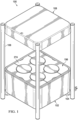
FIG. 1 is a top isometric view of an embodiment of a hydroponic growing unit; -
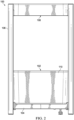
FIG. 2 is a front elevational view of the hydroponic growing unit ofFIG. 1 ; -
FIG. 3 is a back elevational view of the hydroponic growing unit ofFIG. 1 ; -
FIG. 4 is a side elevational view of the hydroponic growing unit ofFIG. 1 ; -
FIG. 5 is a top planar view of the hydroponic growing unit ofFIG. 1 ; -
FIG. 6 is a bottom planar view of the hydroponic growing unit ofFIG. 1 ; -
FIG. 7 is a bottom isometric view of the hydroponic growing unit ofFIG. 1 ; -
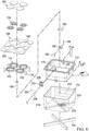
FIG. 8 is an exploded view of a growth unit and support of the hydroponic growing unit ofFIG. 1 ; -
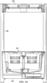
FIG. 9 is a cross-sectional view of the hydroponic growing unit ofFIG. 1 ; -
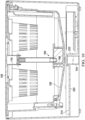
FIG. 10 is a cross-sectional view of the hydroponic growing unit ofFIG. 1 ; -
FIG. 11 is a perspective view of an adapter of the hydroponic growing unit ofFIG. 1 ; -
FIG. 12 is a perspective view of the underside of the adapter ofFIG. 11 ; -
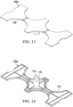
FIG. 13 is a perspective view of a cover plate of the hydroponic growing unit ofFIG. 1 ; -
FIG. 14 is a perspective view of the underside of the cover plate ofFIG. 13 ; -
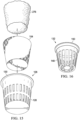
FIG. 15 is an exploded view of a net cup, liner, and growing media of the hydroponic growing unit ofFIG. 1 ; -
FIG. 16 is a perspective view of another net cup of the hydroponic growing unit ofFIG. 1 ; -
FIG. 17 is a perspective view of a lid of the hydroponic growing unit ofFIG. 1 ; -
FIG. 18 is a perspective view of the underside of the lid ofFIG. 17 ; -
FIG. 19 is an exploded view of a sprayer of the hydroponic growing unit ofFIG. 1 ; -
FIG. 20 is a perspective view of the sprayer ofFIG. 19 ; -
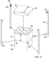
FIG. 21 is an exploded view of the hydroponic growing unit ofFIG. 1 ; -
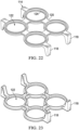
FIG. 22 is a perspective view of a platform of the hydroponic growing unit ofFIG. 1 ; -
FIG. 23 is a perspective view of the platform ofFIG. 22 ; -
FIG. 24 is a cross-sectional view of the hydroponic growing unit ofFIG. 1 ; -
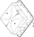
FIG. 25 is a perspective view of a water reservoir of the hydroponic growing unit ofFIG. 1 ; -
FIG. 26 is a perspective view of the underside of the water reservoir ofFIG. 25 ; -
FIG. 27 is a perspective view of a water reservoir of the hydroponic growing unit ofFIG. 1 rotated from the view ofFIG. 25 ; -
FIG. 28 is an exploded view of a lighting system of the hydroponic growing unit ofFIG. 1 ; -
FIG. 29 is a perspective view of the lighting system ofFIG. 28 ; and -
FIG. 30 is a perspective view of the underside of the lighting system ofFIG. 28 . - The following description is intended to convey a thorough understanding of the embodiments by providing various embodiments and details involving a hydroponic unit. It is understood, however, that the disclosure is not limited to these specific embodiments and details, which are illustrative only. It is further understood that one possessing ordinary skill in the art, in light of known devices, systems, and methods, would appreciate the use of the disclosure for its intended purposes and benefits in any number of alternative embodiments, within the scope of the appended claims. As described further below, the hydroponic units described herein improve the ease with which a user grows plants.
- Referring to
FIG. 1 , a hydroponic growingunit 100 in accordance with an embodiment is illustrated. It should be appreciated that the drawings may be simplified and/or illustrative views of a unit, and the hydroponic growingunit 100 may include additional elements that are not depicted. The hydroponic growingunit 100 includes agrowth unit 102 coupled to asupport 104. Thesupport 104 is coupled to a plurality ofcolumns 106, which are in turn coupled to alighting system 108. Each of these components are discussed further below. - With reference to the figures, the
growth unit 102 includes ahousing 110 configured to contain awater reservoir 112. A support structure orplatform 114 may be removably coupled to thewater reservoir 112. Thewater reservoir 112 includesnotches 116 for receivingprojections 118 of theplatform 114. Theplatform 114 includes anupper surface 120 extending to theprojections 118. Theupper surface 120 is web-like and defines a plurality ofapertures 122. In the illustrated embodiment, fourcircular apertures 122 are arranged in a grid pattern. For each of theapertures 122, theplatform 114 includes arim 124. Theapertures 122 are sized to support net cups, such as 4-inch (10,16 cm)net cups 126, which include aframe 128 and alip 130. Theframe 128 passes through theaperture 122, while therim 124 prevents thelip 130 from moving through theaperture 122. In other words, thelip 130 is supported by therim 124 when a 4-inch (10,16 cm)net cup 126 is positioned on theplatform 114. To support a 2-inch (5,08 cm)net cup 132, anadapter 134 may be used. Theadapter 134 includes anouter ring 136 and aninner ring 138 being connected by anangled wall 140. The wall of theinner ring 138 ends in aninner skirt 142, which defines anopening 144. On the underside of theadapter 134 are a series offlanges 146, which provide stabilizing support when theadapter 134 is placed in theplatform 114. When theadapter 134 is positioned in theplatform 114, theouter ring 136 is supported by therim 124, similar to thelip 130 of the 4-inch (10,16 cm)net cup 126. The 2-inch (5,08 cm)net cup 132 may then be placed in theadapter 134 - The
opening 144 of theadapter 134 allows aframe 148 of the 2-inch (5,08 cm)net cup 132 to pass through, while theinner ring 138 supports alip 150 of the 2-inch (5,08 cm)net cup 132. Thus, a user may mix-and-match the desired sizes of net cups used in the hydroponic growingunit 100. Thewater reservoir 112 may include afill line 152 to indicate to a user that the water level should not exceed that level. Thefill line 152 is below, or at a lower level than, a bottom of the 4-inch (10,16 cm)net cup 126 would be when positioned on theplatform 114. Thewater reservoir 112 has a volume large enough to hold at least 1 gallon (3,8 l), at least 2 gallons (7,6 l), or a volume of between 1 and 4 gallons (between 3,8 l and 15,1 l), of water below the fill line. When a 4-inch (10,16 cm)net cup 126 is used, aliner 154 may be included. Theliner 154 allows a plant potted in soil to be transferred to the 4-inch (10,16 cm)net cup 126. - The
liner 154 prevents soil from dropping into the water in thewater reservoir 112. Soil or other particulate matter would foul the water and potentially clog the pump (described below). The roots of the plant would grow through theliner 154, allowing the plant to continue growing. - The
liner 154 may be made of, for example, coconut fiber. Theliner 154 may include a coating such as, for example, a latex coating. - The growing
unit 102 also includes a plurality ofcover plates 156.Sidewalls 158 of eachcover plate 156 are shaped so that, when thecover plates 156 are assembled, thesidewalls 158 define a plurality ofopenings 160. In the illustrated embodiment, theopenings 160 and theapertures 122 are axially aligned. Theopenings 160 are configured to leave each of theapertures 122 of theplatform 114 uncovered. Thus, thecover plates 156 do not prevent a user from placing a plant on theplatform 114. Thesidewalls 158 of eachcover plate 156 also include indentations that allow the user to grip thecover plates 156 and position them on or remove them from thewater reservoir 112. If the growingunit 102 is not used at maximum capacity, alid 162 may be positioned in anyunoccupied aperture 122. Thelids 152, along with thecover plates 156, block light from thewater reservoir 112 and help reduce the growth of algae therein. - A
water circulating system 164 is configured to circulate water in thewater reservoir 112 to the plants growing in the hydroponic growingunit 100. Thewater circulation system 164 includes apump 166 coupled to asprayer 168. Thesprayer 168 is centrally positioned in thewater reservoir 112. Being positioned central to the plants, rather than surrounding the plants, allows for less material (e.g., tubing, multiple nozzles) to be used. Thesprayer 168 includes amulti-pronged nozzle 170 coupled to apump tube 172. Themulti-pronged nozzle 170 directs water towards each plant (i.e., toward thenet cups 126, 132). To properly orient themulti-pronged nozzle 170, theunderside 174 of thecenter cover plate 156a includes aguide 176. Theguide 176 includes a series ofchannels 178. When thecenter cover plate 156a is positioned on theplatform 114, themulti-pronged nozzle 170 orients itself to cause the prongs of thenozzle 170 to enter thechannels 178. This prevents themulti-pronged nozzle 170 from directing water away from the plants. Thus, thegrowth unit 102 is configured to maintain a desired orientation of themulti-pronged nozzle 170. While the water is being circulated, the water is aerated by the air surrounding thenet cups pump tube 172 is removably coupled to thepump 166 via apump adapter 180. Abottom surface 182 of thewater reservoir 112 is sloped and includes apump housing 184 near or at the bottom of the slope. Thepump housing 184 includes asidewall 186 in a shape and size sufficient for thepump 166 to be placed therein. Thesidewall 186 includes an opening so that the inlet of thepump 166 remains unobstructed when thepump 166 is placed within thepump housing 184. Thesidewall 186 may also include achannel 188 for a power cord to pass through. Thepump housing 184 may also include acover 189. The sloped configuration of thebottom surface 182 of thewater reservoir 112 increases the time that thepump 166 is supplied with a sufficient amount of water if the water level in thereservoir 112 decreases. The inlet of thepump 166 may include afilter 190 to reduce the likelihood of particulate matter entering the pump or of buildup (e.g., mineral residue) occurring at the inlet. - The hydroponic growing
unit 100 also includes adrainage tube 192 for draining water from thewater reservoir 112, for example, to clean thewater reservoir 112. Thedrainage tube 192 may be J-shaped, straight, or have any other curvature to it. Themulti-pronged nozzle 170 and apump tube 172 may be separated from thepump adapter 180, and one end of thedrainage tube 192 is coupled to thepump adapter 180. Thepump 166 may remain on or be turned off during this switch. Thedrainage tube 192 extends out of thewater reservoir 112. Thepump 166 is connected to apower source 218 via apump power cord 194. To prevent roots from the plants from wrapping around thepump power cord 194, thewater reservoir 112 includes achannel 196 extending from thepump 166 to thesidewall 198 of thewater reservoir 112. Thechannel 196 includes raisedwalls 200. Thechannel 196 may also include baffles (not shown) that decrease the width of thechannel 196 such that thepump power cord 194 must be squeezed into place. Thus, thepump power cord 194 resists unintentional movement out of thechannel 196. - Referring to the figures, the
water reservoir 112 includes awater level indicator 204. Thewater level indicator 204 comprises amagnetic float 206 and ahousing 208. Thehousing 208 defines an interior 210 that is in communication with the interior of thewater reservoir 112. When the water level rises or lowers in thewater reservoir 112, the water level in thehousing 208 correspondingly rises and lowers along with themagnetic float 206. A sensor, such as an electronic read switch, may be used to determine when themagnetic float 206 reaches a predetermined height. For example, the predetermined level may indicate that a certain volume (e.g., a gallon or 3.8 litres) of water remains in thewater reservoir 112. - With reference to the figures, the
housing 110 defines an interior 212 that includes acompartmentalized bottom surface 214. In the illustrated embodiment, thebottom surface 214 includes fourtriangular segments 216. Thepower source 218 is positioned in one of the triangular segments. If water enters thehousing 110, for example from thewater reservoir 112, the compartmentalization decreases the likelihood of the water reaching thepower source 218. Additionally, thesegment 216 containing thepower source 218 is lower than the remainingsegments 216. Thehousing 110 is removably coupled to thesupport 104. In an embodiment, alower surface 220 of thehousing 110 is configured to receive thesupport 104. As shown in the figures, for example, thelower surface 220 includesgrooves 222. Thegrooves 222 are X-shaped, which corresponds to the X-shape of thesupport 104. Of note, thegrooves 222 are used to compartmentalize thebottom surface 214 of theinterior 212. When thehousing 110 is coupled to thesupport 104, thelower surface 220 of thehousing 110 does not extend past thesupport 104. The hydroponic growingunit 100 also includes apower switch 224 and apower cord 226. Thepower cord 226 may be connected to an electrical outlet, and thepower switch 224 may toggle between an on position and an off position. In the off position, power to thepump 166 andlighting system 108 is stopped. In the on position, power is provided to thepump 166 andlighting system 108 from thepower source 218. - In the illustrated embodiment, the
power switch 224 is positioned on thelower surface 220 of thehousing 110. Thehousing 110 includes at least a first andsecond outlet 228, 230. Thepower cord 226 extends from thepower source 218 through thefirst outlet 228. Similarly, alighting power cord 232 extends from thepower source 218 through the second outlet 230 and into thesupport 104. At least a portion of thesupport 104 is hollow allowing thelighting power cord 232 to extend at least to anend 234 of thesupport 104, as shown in the figures. As discussed above, thesupport 104 is removably coupled to a plurality ofcolumns 106. In the illustrated embodiment, each of thecolumns 106 includes aprojection 236 that extends intohollow ends 234 of thesupport 104. Fasteners, such asscrews 238 andwashers 240 may be used to secure thecolumns 106 to thesupport 104. Thecolumn 106 adjacent to theend 234 of thesupport 104 containing the lighting power connector 225 includes alighting power connector 242. Thelighting power cord 232 and thelighting power connector 242 mate, and thelighting power connector 242 extends up through thecolumn 106. Near or at the top of eachcolumn 106 is ashade support 244 to couple thecolumns 106 to thelighting system 108. Thelighting power connector 242 extends at least from theprojection 236 to thesupport 244. Thecolumns 106 also includeend caps 246 at theends 248 of thecolumns 106. These end caps 246 may be removed, and multiplehydroponic units 100 may be stacked together. - With reference to the figures, the
lighting system 108 includes ashade 250, acontrol board 252, and alighting panel 254. Theshade 250 includes atop surface 256 and asidewall 258 extending therefrom. Thesidewall 258 includesindentations 260, which mate with the shade supports 244 of thecolumns 106. Thesidewall 258 acts to redirect light from thelighting panel 254 towards the plants below. This also allows a user to be at eye level with thelighting panel 254 without having light shine directly at them. Theshade 250 also includes one ormore brackets 262 or inserts 263. Thebrackets 262 and/or inserts 263 extend along at least a portion of thesidewall 258. Thebrackets 262 and/or inserts 263 increase the strength of thesidewall 258, which allows a user to more easily reposition the hydroponic growingunit 100 by gripping theshade 250. Theshade 250 may also include or be coupled to a chargingstation 264. The chargingstation 264 may be, for example, conductive or inductive. Theinductive charging station 264 may be directly or indirectly coupled to thecontrol board 252 and/or thelighting power connector 242. Theinductive charging station 264 would allow a user to charge a device, such as a mobile phone, on top of theshade 250. The hydroponic growingunit 100 may also include a charging outlet, such as a 120 V AC outlet. - Still referring to the figures, the
control board 252 is coupled to anunderside 266 of theshade 250. Thecontrol board 252 is electronically coupled to thelighting power connector 242. Thecontrol board 252 may include a wireless protocol, such as Bluetooth® or another wireless protocol, to communicate with a reader device, such as a mobile phone. Thelighting panel 254 includes a series oflights 268, such as LEDs. Thelights 268 may include one or more wavelength and color. The wattage of the lights may be, for example, 60 W. In an embodiment, the wavelength of the light from thelights 268 may be in a range of 400 nm to 700 nm. Thelighting system 108 also includes alens 270 between thelighting panel 254 and the growth unit 102 (i.e., the plants). The hydroponic growingunit 100 also includes aswitch 272 for turning thelights 268 on and off. Theswitch 272 may also be used to dim thelights 268. In the illustrated embodiment, theswitch 272 is on thetop surface 256 of theshade 250 and arelated sensor 273 is on the opposite side of theshade 250. Theswitch 272 may be, for example, a capacitive switch or a button. In embodiments where theswitch 272 is capacitive, there is not opening in thetop surface 256 for wiring to pass therethrough. This creates a more secure environment for thecontrol board 252 andlighting panel 254 in case something is spilled on theshade 250. The border of theswitch 272 may be raised from thetop surface 256 to allow a user to easily determine where theswitch 272 is. - The
control board 252 may be programmed to turn thelights 268 on for a set period of time each day. In various embodiments, the daily light period may be in a range of 12 hours to 16 hours, or 14 hours. This removes the need for the user to actively turn on and off the lights, which improves the likelihood that the plants receive sufficient light each day. In an embodiment, thecontrol board 252 may be programmed to turn thelights 268 back on after a set period of time after theswitch 272 is activated (e.g., to dim or turn off the lights 268). - The
lighting system 108 is fixed to thegrowth unit 106. In other words, the height between thelighting system 108 and the upper surface of the growth unit (e.g., atop surface 274 of the cover plates 156) is fixed. The height (H) from thelighting panel 254 to thetop surface 274 of thecover plates 156 may be in a range of, for example, 14 to 18 inches (35,56 to 45,72 cm). In an embodiment, the height (H) may be 16 inches (40,64 cm). Thelighting system 108, at the fixed height (H) is configured to provide sufficient light to seeds, seedlings, or plants positioned in thegrowth unit 102. - In various embodiments, the hydroponic growing
unit 100 may be configured to indicate one or more conditions to a user. In an embodiment, when the sensor senses that themagnetic float 206 is at the predetermined level, an indicator notes that the water level is at a predetermined level. The indicator lets the user know that more water should be added to thewater reservoir 112. In an embodiment, the indicator is the repeated flashing of thelights 268. For example, thelights 268 may repeatedly flash at a predetermined interval, such as every 10 seconds, until the user adds more water to cause the water level to rise above the predetermined level. This reduces the chances of thepump 166 running dry. The hydroponic growingunit 100, in an embodiment, may be configured to indicate that thepump 166 has stopped working. For example, thelights 268 may constantly flash until the pump is turned off or, if something is clogging the pump, until the pump is able to run again. Additionally, in an embodiment, an indicator may let the user know that the wireless protocol, such as Bluetooth®, has been activated. For example, thelights 268 may flash once to indicate that the Bluetooth® is now available for nearby devices to locate. - Various components of the hydroponic growing
unit 100 may be made of, for example, metal or plastic. In various embodiments, thehousing 110 and theshade 250 may be made of the same material. For example, thehousing 110 and/or theshade 250 are made of acrylonitrile butadiene styrene resin. The material may include UV inhibitors to avoid discoloration of the material over time. In various embodiments, one or more components may be made of a reinforced material, such as glass-filled nylon, for increased strength. For example, theplatform 114 may be made of glass-filled nylon. - Various plants may be grown in the hydroponic growing
unit 100. Suitable plants include, without limitation, leafy plants, herbs, flowering plants. - In use, a seed, seedling, or plant may be placed in one of the 4-inch (10,16 cm)
net cups 126 and/or the 2-inch (5,08 cm)net cups 132. As discussed above, a plant already rooted in a material, such as soil, may also be added to the hydroponic growingunit 100. A seed, before it has grown or at any stage of germination, may be positioned in growing media in thenet cups media 172 is adapted to fully or partially fill the interior space defined by thenet cups seed pods 100 may be classified and rated as organic. In the illustrated embodiment, the growingmedia 276 is a molded cylindrical plug sized to fit in the 2-inch (5,08 cm)net cup 132. Because the 2-inch (5,08 cm)net cup 132 is tapered, the cylindrical growingmedia 276 fits snugly in the 2-inch (5,08 cm)net cup 132. The 2-inch (5,08 cm)net cup 132 may bow slightly due to the presence of the growingmedia 276. When the 2-inch (5,08 cm)net cup 132 is not full, the sound of water splashing against the sides of the 2-inch (5,08 cm)net cup 132 may be noticeable. Because the growingmedia 276 fills the 2-inch (5,08 cm)net cup 132, this sound is significantly reduced. In an embodiment, the growingmedia 276 may have a diameter of 4.8 cm and a height of 5.2 cm. - To aid in successful growth of the plants in the hydroponic growing
unit 100, nutrients may be added to the water in thewater reservoir 112. In various embodiments, nutrient composition is added to the water periodically. The nutrient composition may be, for example, in powder or liquid form. The nutrient composition may be added, for example, every two weeks or once a month. Increasing the time between additions of the nutrient composition improves the ease of growing plants using the hydroponic growingunit 100. The nutrient solution may have a self-balancing pH. As the plant or plants grow in the hydroponic growing unit, the roots of the plants may reach the water residing in the water reservoir. The roots may grow down to the pump. The pump housing helps to protect the pump from the roots entering the pump and interfering with its operation and ability to intake water. As described above, thechannel 196 helps to protect thepump power cord 194 from root interference. Once the roots have reached the water, it is still desirable to have thepump 166 to be powered on so that the water is still aerated. Without aeration, the survival time of the plants is limited. The water does not need to be replaced during the lifecycle of the plants growing therein. - The hydroponic growing
unit 100 may act as a piece of furniture in a home. For example, the hydroponic growingunit 100 may be used as an end table. In various embodiments, a total height of the hydroponic growingunit 100 may be in a range from 26 inches to 30 inches (66 cm to 76,2 cm), or may be 28 inches (71,1 cm). The hydroponic growingunit 100 may come in a variety of external shapes. In the illustrated embodiment, the exterior of the hydroponic growingunit 100 is substantially square-shaped and has rounded edges. As described above, the hydroponic growing units according to one or more embodiments and/or methods may provide a method of growing seeds and/or plants by: automating the water, nutrients, and light provided each day; reducing the frequency that nutrients must be added; and not requiring the water to be changed during the lifecycle of the plants. - In certain illustrative embodiments, each of the components described herein are injection molded to a desired shape. In some embodiments, each component may be molded as a single, unitary molded part. In other embodiments, the component may be molded in multiple parts that are joined or attached together to form the component. The various means for designing molds, and joining various parts to form one component will be understood by one familiar with such processes and parts.
- Reference throughout the specification to "various embodiments," "some embodiments," "one embodiment," "some example embodiments," "one example embodiment," or "an embodiment" means that a particular feature, structure, or characteristic described in connection with any embodiment is included in at least one embodiment. Thus, appearances of the phrases "in various embodiments," "in some embodiments," "in one embodiment," "some example embodiments," "one example embodiment," or "in an embodiment" in places throughout the specification are not necessarily all referring to the same embodiment. Furthermore, the particular features, structures or characteristics may be combined in any suitable manner in one or more embodiments.
- Accordingly, the various embodiments are not to be limited in scope by the specific embodiments described herein. Further, although some of the embodiments have been described herein in the context of a particular implementation in a particular environment for a particular purpose, those of ordinary skill in the art should recognize that its usefulness is not limited thereto and that the various embodiments can be beneficially implemented in any number of environments for any number of purposes. Accordingly, the claims set forth below should be construed in view of the full breadth of the embodiments as disclosed herein. While the foregoing description includes many details and specificities, it is to be understood that these have been included for purposes of explanation only, and are not to be interpreted as limitations of the various embodiments. Many modifications to the embodiments described above can be made without departing from the scope of this description, the invention being defined by the appended claims.
Claims (15)
- A hydroponic growing apparatus (100), comprising:a housing (110);a water reservoir (112) positioned in the housing (110) and comprising a bottom surface and an open top surface;a support structure (114) configured to fit into the open top surface of the housing (110) and defining a plurality of openings (122);at least one cover plate (156) configured to fit over the support structure (114) in the open top surface of the housing, the at least one cover plate (156) comprising a plurality of cut-outs corresponding to the plurality of openings (122) of the support structure (114);a pump (166) positioned in the water reservoir (112), the pump (166) comprising an inlet and an outlet;a sprayer (168) coupled to the outlet of the pump (166); anda lighting system (108) coupled to the housing (110);characterized in that the hydroponic growing apparatus (100) further comprises:a power source (218) positioned in the housing (110); anda pump power cord (194) extending from the pump (166) in the water reservoir (112) to the power source (218) in the housing (110), wherein the bottom surface of the water reservoir (112) comprises a channel (196) including raised walls (200) configured to receive the pump power cord (194).
- The hydroponic growing apparatus (100) of claim 1, wherein a fixed distance between a lower surface of the lighting system (108) and an upper surface of the at least one cover plate (156) is in a range of 14 to 18 inches (35.5 cm to 45.7 cm).
- The hydroponic growing apparatus (100) of claim 1 or claim 2, wherein the lighting system (108) includes a control board (252), a lens (270), and a lighting panel (254) including lights (268).
- The hydroponic growing apparatus (100) of any one of claims 1-3, wherein the hydroponic growing apparatus (100) is configured to turn the lighting system (108) on for a period of time each day, the period of time being in a range of 12 to 16 hours.
- The hydroponic growing apparatus (100) of any one of claims 1-4, further comprising at least one opening defined by the plurality of cut-outs of the cover plates (156), the at least one opening overlapping at least one opening of the plurality of openings (122) of the support structure (114).
- The hydroponic growing apparatus (100) of any one of claims 1-5, further comprising a water level (204) indicator including a magnetic float (206).
- The hydroponic growing apparatus (100) of any one of claims 1-6, further comprising at least one basket of a size and shape to fit into any of the plurality of openings (122) in the support structure (114).
- The hydroponic growing apparatus (100) of any one of claims 1-7, wherein the plurality of openings (122) is four openings arranged in a grid.
- The hydroponic growing apparatus (100) of any one of claims 1-8, wherein the sprayer (168) comprises a nozzle (170) below the support structure (114), the nozzle (170) located centrally of the plurality of openings (122) of the support structure (114).
- The hydroponic growing apparatus (100) of any one of claims 1-9, further comprising a drain tube (192) selectively connected to the outlet of the pump (166) that is repositionable to convey water entering the inlet of the pump (166) to a location external to the housing (110).
- A method of hydroponically growing a plant comprising:positioning a plant rooted in a growing material in a net cup (126, 132); andplacing the net cup (126, 132) in the hydroponic growing apparatus (100) of claim 1.
- The method of claim 11, further comprising, before positioning the plant, positioning a liner (154) in the net cup (126, 132).
- The method of claim 11 or claim 12, further comprising providing light to the plant from the lighting system (108) of the hydroponic growing apparatus (100) for 12 to 16 hours daily.
- The method of any one of claims 11-13, further comprising periodically adding a nutrient composition to water in a water reservoir (112) of the hydroponic growing apparatus.
- A kit comprising:the hydroponic growing apparatus (100) of claim 1;one or more net cups (126, 132) of a first size;one or more net cups (126, 132) of a second size, the second size being different from the first size;one or more adapters (134); andone or more cylindrical plugs (276) sized to fit in the one or more net cups (126, 132) of the second size.
Applications Claiming Priority (2)
| Application Number | Priority Date | Filing Date | Title |
|---|---|---|---|
| US201862770213P | 2018-11-21 | 2018-11-21 | |
| PCT/US2019/062413 WO2020106839A1 (en) | 2018-11-21 | 2019-11-20 | Hydroponic growing unit |
Publications (2)
| Publication Number | Publication Date |
|---|---|
| EP3883366A1 EP3883366A1 (en) | 2021-09-29 |
| EP3883366B1 true EP3883366B1 (en) | 2023-06-07 |
Family
ID=68848490
Family Applications (1)
| Application Number | Title | Priority Date | Filing Date |
|---|---|---|---|
| EP19818442.6A Active EP3883366B1 (en) | 2018-11-21 | 2019-11-20 | Hydroponic growing apparatus and method of hydroponically growing a plant |
Country Status (8)
| Country | Link |
|---|---|
| US (1) | US11503783B2 (en) |
| EP (1) | EP3883366B1 (en) |
| JP (1) | JP7531487B2 (en) |
| CN (1) | CN113163726B (en) |
| AU (1) | AU2019385484B2 (en) |
| CA (1) | CA3120698A1 (en) |
| MX (1) | MX2021005079A (en) |
| WO (1) | WO2020106839A1 (en) |
Families Citing this family (20)
| Publication number | Priority date | Publication date | Assignee | Title |
|---|---|---|---|---|
| US11483982B2 (en) * | 2018-05-01 | 2022-11-01 | Wen-Hao Li | Planting structure capable of controlling growth conditions and recycling nutrient solution |
| US10990875B2 (en) * | 2018-11-28 | 2021-04-27 | International Business Machines Corporation | Neural network forecasting for tiered hydroponic natural farming configurations |
| US11337387B2 (en) * | 2019-07-12 | 2022-05-24 | Rise Gardens Inc. | Hydroponic system and apparatus having removable growing structures for multiple types of plants |
| US11991962B2 (en) * | 2020-04-14 | 2024-05-28 | Advanced Autoponics, LLC | Advanced nutrient film and well |
| US12290031B2 (en) * | 2020-12-10 | 2025-05-06 | Keerti Ayakannu | System and method for propagating, transporting, and growing free-rooted plants |
| US20220210981A1 (en) * | 2021-01-06 | 2022-07-07 | John Paul D'Acquisto | Method For Optimizing Growth Of Microgreens |
| EP4052566B1 (en) * | 2021-03-05 | 2026-02-11 | Click & Grow OÜ | An indoor garden device |
| GB2604606B (en) * | 2021-03-08 | 2024-03-20 | Burgess Simon | Hydroponic apparatus |
| GB2606048B (en) * | 2021-04-20 | 2023-04-26 | Gyroplant Ltd | A reusable growing plug and hydroponic system for a growing crop |
| DE102021111372A1 (en) * | 2021-05-03 | 2022-11-03 | Greenling UG (haftungsbeschränkt) | Planting arrangement and method of arranging a planting arrangement |
| CN115669523A (en) * | 2021-07-27 | 2023-02-03 | 苏州金世达工具制造有限公司 | Indoor hydroponic device and control method |
| KR102958997B1 (en) * | 2021-08-30 | 2026-04-30 | 엘지전자 주식회사 | Simple plant cultivator |
| US20230077746A1 (en) * | 2021-09-15 | 2023-03-16 | Julia Flanary | Pod Insert for Pod Gardening Systems |
| JP2024536804A (en) * | 2021-09-21 | 2024-10-08 | ヘリポニックス エルエルシー | Seed Cartridge Assembly for Enclosed Growing Environments |
| US20230172119A1 (en) * | 2021-12-02 | 2023-06-08 | Karpos Cultivation | Methods, systems, apparatuses and devices for facilitating cultivation of plants |
| USD1007910S1 (en) * | 2022-06-01 | 2023-12-19 | Shenzhen Solhydro Technology Co., Ltd. | Hydroponic growing system |
| WO2024023663A1 (en) * | 2022-07-25 | 2024-02-01 | Linea Colombo Srl | Hydroponic tray |
| IT202200015570A1 (en) * | 2022-07-25 | 2024-01-25 | Linea Colombo Srl | TILE FOR THE CREATION OF HYDROPONIC CULTURE FOR GREEN PAVING |
| USD1011231S1 (en) * | 2023-05-02 | 2024-01-16 | Hao Pan | Hydroponic tower |
| USD1059208S1 (en) * | 2023-09-21 | 2025-01-28 | Shrooly LTD | Indoor cultivation apparatus |
Family Cites Families (63)
| Publication number | Priority date | Publication date | Assignee | Title |
|---|---|---|---|---|
| US1959510A (en) | 1931-12-02 | 1934-05-22 | Theodorus Van Waveren | Package for flower bulbs |
| US2740546A (en) | 1952-10-20 | 1956-04-03 | Kowalski Benedict | Bucket having removable compartments |
| US2930162A (en) | 1957-09-30 | 1960-03-29 | Mulford Brothers Company | Shipping and growing device for bulbs |
| US3984941A (en) | 1975-09-29 | 1976-10-12 | Chetta Jr Nicholas J | Table top waste receptacle |
| US4646628A (en) | 1985-10-24 | 1987-03-03 | Lederman Elsie J | Cooking utensil |
| US5282335A (en) | 1992-03-03 | 1994-02-01 | Holtkamp Reinhold Jr | Self-watering dish garden for plants |
| US5394647A (en) | 1994-02-22 | 1995-03-07 | Blackford, Jr.; John W. | Hydroponic plant growing system and structure |
| US5502923A (en) | 1995-04-25 | 1996-04-02 | Bradshaw; John A. | Hydroponic growth systems and methods |
| US6038812A (en) | 1998-09-21 | 2000-03-21 | Belokin; Paul | Vase with support for display |
| US20030066238A1 (en) | 2001-10-04 | 2003-04-10 | Blake Whisenant | Plant cultivation apparatus and method for growing crops in sequence |
| US7179173B2 (en) | 2002-03-25 | 2007-02-20 | Nbgs International Inc. | Control system for water amusement devices |
| US6901700B2 (en) | 2002-08-13 | 2005-06-07 | Grzegorz Trabka | Combination planter |
| US20070271841A1 (en) * | 2004-03-16 | 2007-11-29 | Aerogrow International, Inc. | Devices and methods for growing plants |
| US20080282610A1 (en) | 2004-03-16 | 2008-11-20 | Aerogrow International, Inc. | Devices and methods for growing plants |
| US7069691B2 (en) | 2004-05-27 | 2006-07-04 | Lawrence L. Brooke | Hydroponics plant cultivation assembly for diverse sizes of pots and plants |
| US8261486B2 (en) * | 2004-09-15 | 2012-09-11 | Aerogrow International, Inc. | Systems and methods for controlling liquid delivery and distribution to plants |
| DE202005009893U1 (en) | 2005-06-23 | 2005-12-22 | Leithold, Monika | Plant e.g. kitchen plant, holding tray, has side wall extending from base to open edge, and lid-type insert or attachment fixed at edge and provided with openings whose diameter is determined for accommodating plant pots |
| CN201004885Y (en) * | 2006-03-29 | 2008-01-16 | 干成剑 | Soilless culturing type kitchen vegetable garden |
| US9456560B1 (en) | 2007-03-21 | 2016-10-04 | Macshappie Enterprises, Inc. | Tree and plant watering systems |
| US20080313960A1 (en) | 2007-06-19 | 2008-12-25 | Norvitch Daniel A | Mobile planter |
| ATE504203T1 (en) * | 2007-08-30 | 2011-04-15 | Viherasema Oy | SYSTEM FOR HYDROPONIC PLANT CULTIVATION |
| US20090151248A1 (en) * | 2007-10-30 | 2009-06-18 | Aerogrow International, Inc. | Devices and methods for growing plants |
| US8726568B2 (en) * | 2007-11-20 | 2014-05-20 | Daniel J. Wilson | Apparatus for growing living organisms |
| KR101040580B1 (en) * | 2008-09-19 | 2011-06-13 | 대한민국 | Raising Seedings of Multistage Apparatus |
| CA2744905A1 (en) | 2008-11-26 | 2010-06-03 | Jeremy Pindus | Hydroponic system for providing controlled environment to grow plants and apparatus therefor |
| KR200460757Y1 (en) * | 2009-06-24 | 2012-06-04 | 전형기 | A prefabricated and simple raising seedings apparatus having a luminous portion |
| US8291639B2 (en) | 2009-09-09 | 2012-10-23 | S and E Properties, Inc. | Growing system for hydroponics and/or aeroponics |
| CN201911183U (en) * | 2010-12-09 | 2011-08-03 | 北京中环易达设施园艺科技有限公司 | Fish and vegetable co-existing small household device |
| CN201919446U (en) * | 2010-12-16 | 2011-08-10 | 北京中环易达设施园艺科技有限公司 | Eggshell-type houseplant growing device |
| JP5769435B2 (en) * | 2011-01-20 | 2015-08-26 | 有限会社長尾デザイン事務所 | Plant cultivation equipment |
| US8919041B2 (en) * | 2012-02-09 | 2014-12-30 | Vegherb, Llc | Lighting system for use in raised bed gardening or landscaping |
| CA3125973C (en) | 2012-02-17 | 2026-02-17 | Oms Investments, Inc. | Plant growing system and methods of using the same |
| US8667734B2 (en) * | 2012-03-28 | 2014-03-11 | Dan Johnson | Hydroponic plant container with highly oxygenated nutrient solution using continuous air injection and continuous coriolis effect mixing |
| KR101211246B1 (en) * | 2012-04-10 | 2012-12-11 | 김완중 | Water culture system |
| CN202819205U (en) * | 2012-06-22 | 2013-03-27 | 济南佰福康物联网技术有限公司 | Intelligent module type sprout-stock vegetable cultivation system |
| KR101251203B1 (en) * | 2012-10-30 | 2013-04-12 | 박종필 | Plant grower using artificial light |
| ITMI20122055A1 (en) * | 2012-11-30 | 2014-05-31 | Galaxy Color S R L | DEVICE FOR DOMESTIC HYDROPONIC CULTIVATION |
| EP3476206A1 (en) * | 2013-03-14 | 2019-05-01 | Crop One Holdings, Inc. | Led light timing in a high growth, high density, closed environment system |
| CN203368681U (en) | 2013-06-17 | 2013-12-25 | 威立达数码科技(深圳)有限公司 | Speaker box and audio playing device |
| US20150208598A1 (en) | 2014-01-29 | 2015-07-30 | Lynn R. Kern | Hydroponic Nutrient Delivery Gardening System |
| US8998473B1 (en) | 2014-03-10 | 2015-04-07 | Terry W Anderson | Light reflector structure for horticultural lamps |
| DK201400055U3 (en) * | 2014-03-28 | 2015-07-10 | Plantui Oy | Hydroponic cultivation device |
| DE202014101488U1 (en) | 2014-03-28 | 2014-06-12 | Plantui Oy | Device for hydroponic cultivation |
| US20150351325A1 (en) * | 2014-06-07 | 2015-12-10 | Greenhouse Hvac Llc | Led grow light with automatic height adjustment |
| US10104845B2 (en) * | 2015-05-31 | 2018-10-23 | EZinGrow Ltd. | Hydrophonic planter |
| CN204811371U (en) * | 2015-06-30 | 2015-12-02 | 潍坊友容实业有限公司 | Nutrient solution water planting system |
| CN105340718A (en) * | 2015-11-30 | 2016-02-24 | 杭州宅耕农业科技有限公司 | Household plant cultivating device |
| US20170303482A1 (en) * | 2016-04-20 | 2017-10-26 | Tex Ag IP, LLC | Hydroponic Plant Growing Apparatus |
| US10149442B2 (en) | 2016-07-08 | 2018-12-11 | Thomas Luke Hohmann | Automated planter apparatus |
| CN205848244U (en) * | 2016-07-25 | 2017-01-04 | 常州聚诚科技有限公司 | Plant water smoke cultivator |
| JP6834009B2 (en) * | 2016-10-03 | 2021-02-24 | グッドウィン, ランディー, エム.GOODWIN, Randy, M. | Hydroponics unit |
| CN206686837U (en) * | 2017-04-11 | 2017-12-01 | 西南科技大学 | Houseplant breeding apparatus associated with a kind of LED and mist training |
| US10999985B2 (en) | 2017-05-11 | 2021-05-11 | Michael C. WATSON | Fogponic plant growth system |
| CN107343470A (en) | 2017-08-14 | 2017-11-14 | 东莞市中实创半导体照明有限公司 | Desktop hydroponic plant planter with air-cleaning function |
| CN207639364U (en) * | 2017-09-15 | 2018-07-24 | 中实创科技(广东)有限公司 | Water planting plants laying rack |
| CN107926340A (en) * | 2017-10-20 | 2018-04-20 | 浙江胜百信息科技有限公司 | A kind of plant growing machine that can adjust illumination height |
| USD850323S1 (en) | 2018-01-03 | 2019-06-04 | Orecision Cultivation Systems Holdings, LLC | Planting assembly |
| CN107950375A (en) * | 2018-01-12 | 2018-04-24 | 杭州智控网络有限公司 | A kind of plant growing machine |
| US20200084983A1 (en) * | 2018-09-14 | 2020-03-19 | Aqua Design Innovations | Automated Hydroponic Greenhouses |
| KR101892977B1 (en) * | 2018-06-20 | 2018-08-30 | 권우진 | Flowerpot using water vapor |
| GB2576761B (en) * | 2018-08-31 | 2021-02-24 | Hydrogarden Ltd | Apparatus for use when growing plants |
| CN108935058A (en) * | 2018-09-06 | 2018-12-07 | 东莞市汇林包装有限公司 | A kind of cultivation apparatus without soil of environmental protection |
| KR102340090B1 (en) * | 2021-07-28 | 2021-12-15 | 황재택 | module type hydroponics planter |
-
2019
- 2019-11-20 US US16/689,636 patent/US11503783B2/en active Active
- 2019-11-20 EP EP19818442.6A patent/EP3883366B1/en active Active
- 2019-11-20 AU AU2019385484A patent/AU2019385484B2/en active Active
- 2019-11-20 MX MX2021005079A patent/MX2021005079A/en unknown
- 2019-11-20 CA CA3120698A patent/CA3120698A1/en active Pending
- 2019-11-20 CN CN201980076787.0A patent/CN113163726B/en active Active
- 2019-11-20 WO PCT/US2019/062413 patent/WO2020106839A1/en not_active Ceased
- 2019-11-20 JP JP2021525244A patent/JP7531487B2/en active Active
Also Published As
| Publication number | Publication date |
|---|---|
| AU2019385484B2 (en) | 2025-09-25 |
| JP7531487B2 (en) | 2024-08-09 |
| CN113163726A (en) | 2021-07-23 |
| EP3883366A1 (en) | 2021-09-29 |
| MX2021005079A (en) | 2021-08-11 |
| AU2019385484A1 (en) | 2021-06-03 |
| US11503783B2 (en) | 2022-11-22 |
| CA3120698A1 (en) | 2020-05-28 |
| WO2020106839A1 (en) | 2020-05-28 |
| CN113163726B (en) | 2023-04-07 |
| JP2022507075A (en) | 2022-01-18 |
| US20200154659A1 (en) | 2020-05-21 |
Similar Documents
| Publication | Publication Date | Title |
|---|---|---|
| US11503783B2 (en) | Hydroponic growing unit | |
| JP7193561B2 (en) | hydroponics unit | |
| AU2020101617A4 (en) | A Kind of Plant Seedling Raising Bracket | |
| US20070271841A1 (en) | Devices and methods for growing plants | |
| US20050246955A1 (en) | Devices and methods for growing plants | |
| KR20130134662A (en) | Continuous water supply available flowerbeds | |
| KR102026448B1 (en) | Hydroponic cultivation apparatus | |
| KR20110010141A (en) | Stacked Hydroponic Cultivator with Flow Path | |
| KR102300685B1 (en) | Plant breeding water supply | |
| KR101176761B1 (en) | Auto Aquiculture Device Available Water Load Of A Build Method | |
| HK40061270B (en) | Hydroponic growing apparatus and method of hydroponically growing a plant | |
| HK40061270A (en) | Hydroponic growing apparatus and method of hydroponically growing a plant | |
| KR20180078992A (en) | Hydroponics flower port | |
| HK40081574B (en) | Hydroponic growing unit | |
| KR200278197Y1 (en) | A pot for cultivating plants | |
| HK40081574A (en) | Hydroponic growing unit | |
| KR200493718Y1 (en) | Flowerport of pipe type for cultivating a plant | |
| CN221670494U (en) | Plant root system guiding growth container and tray | |
| KR200143753Y1 (en) | Seedling pot of crop | |
| HK40018407A (en) | Hydroponic growing unit | |
| HK40018407B (en) | Hydroponic growing unit | |
| KR200183234Y1 (en) | The flat with a draining hoop | |
| KR20230016115A (en) | Bottom watering type seedling methods and device using jiffy pot | |
| KR20160005808A (en) | plant pot |
Legal Events
| Date | Code | Title | Description |
|---|---|---|---|
| STAA | Information on the status of an ep patent application or granted ep patent |
Free format text: STATUS: UNKNOWN |
|
| STAA | Information on the status of an ep patent application or granted ep patent |
Free format text: STATUS: THE INTERNATIONAL PUBLICATION HAS BEEN MADE |
|
| PUAI | Public reference made under article 153(3) epc to a published international application that has entered the european phase |
Free format text: ORIGINAL CODE: 0009012 |
|
| STAA | Information on the status of an ep patent application or granted ep patent |
Free format text: STATUS: REQUEST FOR EXAMINATION WAS MADE |
|
| 17P | Request for examination filed |
Effective date: 20210519 |
|
| AK | Designated contracting states |
Kind code of ref document: A1 Designated state(s): AL AT BE BG CH CY CZ DE DK EE ES FI FR GB GR HR HU IE IS IT LI LT LU LV MC MK MT NL NO PL PT RO RS SE SI SK SM TR |
|
| DAV | Request for validation of the european patent (deleted) | ||
| DAX | Request for extension of the european patent (deleted) | ||
| REG | Reference to a national code |
Ref country code: HK Ref legal event code: DE Ref document number: 40061270 Country of ref document: HK |
|
| GRAP | Despatch of communication of intention to grant a patent |
Free format text: ORIGINAL CODE: EPIDOSNIGR1 |
|
| STAA | Information on the status of an ep patent application or granted ep patent |
Free format text: STATUS: GRANT OF PATENT IS INTENDED |
|
| INTG | Intention to grant announced |
Effective date: 20221206 |
|
| GRAS | Grant fee paid |
Free format text: ORIGINAL CODE: EPIDOSNIGR3 |
|
| GRAA | (expected) grant |
Free format text: ORIGINAL CODE: 0009210 |
|
| STAA | Information on the status of an ep patent application or granted ep patent |
Free format text: STATUS: THE PATENT HAS BEEN GRANTED |
|
| AK | Designated contracting states |
Kind code of ref document: B1 Designated state(s): AL AT BE BG CH CY CZ DE DK EE ES FI FR GB GR HR HU IE IS IT LI LT LU LV MC MK MT NL NO PL PT RO RS SE SI SK SM TR |
|
| REG | Reference to a national code |
Ref country code: GB Ref legal event code: FG4D |
|
| REG | Reference to a national code |
Ref country code: CH Ref legal event code: EP Ref country code: AT Ref legal event code: REF Ref document number: 1571875 Country of ref document: AT Kind code of ref document: T Effective date: 20230615 |
|
| REG | Reference to a national code |
Ref country code: DE Ref legal event code: R096 Ref document number: 602019030620 Country of ref document: DE |
|
| REG | Reference to a national code |
Ref country code: LT Ref legal event code: MG9D |
|
| REG | Reference to a national code |
Ref country code: NL Ref legal event code: MP Effective date: 20230607 |
|
| PG25 | Lapsed in a contracting state [announced via postgrant information from national office to epo] |
Ref country code: SE Free format text: LAPSE BECAUSE OF FAILURE TO SUBMIT A TRANSLATION OF THE DESCRIPTION OR TO PAY THE FEE WITHIN THE PRESCRIBED TIME-LIMIT Effective date: 20230607 Ref country code: NO Free format text: LAPSE BECAUSE OF FAILURE TO SUBMIT A TRANSLATION OF THE DESCRIPTION OR TO PAY THE FEE WITHIN THE PRESCRIBED TIME-LIMIT Effective date: 20230907 Ref country code: ES Free format text: LAPSE BECAUSE OF FAILURE TO SUBMIT A TRANSLATION OF THE DESCRIPTION OR TO PAY THE FEE WITHIN THE PRESCRIBED TIME-LIMIT Effective date: 20230607 |
|
| REG | Reference to a national code |
Ref country code: AT Ref legal event code: MK05 Ref document number: 1571875 Country of ref document: AT Kind code of ref document: T Effective date: 20230607 |
|
| PG25 | Lapsed in a contracting state [announced via postgrant information from national office to epo] |
Ref country code: RS Free format text: LAPSE BECAUSE OF FAILURE TO SUBMIT A TRANSLATION OF THE DESCRIPTION OR TO PAY THE FEE WITHIN THE PRESCRIBED TIME-LIMIT Effective date: 20230607 Ref country code: NL Free format text: LAPSE BECAUSE OF FAILURE TO SUBMIT A TRANSLATION OF THE DESCRIPTION OR TO PAY THE FEE WITHIN THE PRESCRIBED TIME-LIMIT Effective date: 20230607 Ref country code: LV Free format text: LAPSE BECAUSE OF FAILURE TO SUBMIT A TRANSLATION OF THE DESCRIPTION OR TO PAY THE FEE WITHIN THE PRESCRIBED TIME-LIMIT Effective date: 20230607 Ref country code: LT Free format text: LAPSE BECAUSE OF FAILURE TO SUBMIT A TRANSLATION OF THE DESCRIPTION OR TO PAY THE FEE WITHIN THE PRESCRIBED TIME-LIMIT Effective date: 20230607 Ref country code: HR Free format text: LAPSE BECAUSE OF FAILURE TO SUBMIT A TRANSLATION OF THE DESCRIPTION OR TO PAY THE FEE WITHIN THE PRESCRIBED TIME-LIMIT Effective date: 20230607 Ref country code: GR Free format text: LAPSE BECAUSE OF FAILURE TO SUBMIT A TRANSLATION OF THE DESCRIPTION OR TO PAY THE FEE WITHIN THE PRESCRIBED TIME-LIMIT Effective date: 20230908 |
|
| PG25 | Lapsed in a contracting state [announced via postgrant information from national office to epo] |
Ref country code: FI Free format text: LAPSE BECAUSE OF FAILURE TO SUBMIT A TRANSLATION OF THE DESCRIPTION OR TO PAY THE FEE WITHIN THE PRESCRIBED TIME-LIMIT Effective date: 20230607 |
|
| PG25 | Lapsed in a contracting state [announced via postgrant information from national office to epo] |
Ref country code: SK Free format text: LAPSE BECAUSE OF FAILURE TO SUBMIT A TRANSLATION OF THE DESCRIPTION OR TO PAY THE FEE WITHIN THE PRESCRIBED TIME-LIMIT Effective date: 20230607 |
|
| PG25 | Lapsed in a contracting state [announced via postgrant information from national office to epo] |
Ref country code: IS Free format text: LAPSE BECAUSE OF FAILURE TO SUBMIT A TRANSLATION OF THE DESCRIPTION OR TO PAY THE FEE WITHIN THE PRESCRIBED TIME-LIMIT Effective date: 20231007 |
|
| PG25 | Lapsed in a contracting state [announced via postgrant information from national office to epo] |
Ref country code: SM Free format text: LAPSE BECAUSE OF FAILURE TO SUBMIT A TRANSLATION OF THE DESCRIPTION OR TO PAY THE FEE WITHIN THE PRESCRIBED TIME-LIMIT Effective date: 20230607 Ref country code: SK Free format text: LAPSE BECAUSE OF FAILURE TO SUBMIT A TRANSLATION OF THE DESCRIPTION OR TO PAY THE FEE WITHIN THE PRESCRIBED TIME-LIMIT Effective date: 20230607 Ref country code: RO Free format text: LAPSE BECAUSE OF FAILURE TO SUBMIT A TRANSLATION OF THE DESCRIPTION OR TO PAY THE FEE WITHIN THE PRESCRIBED TIME-LIMIT Effective date: 20230607 Ref country code: PT Free format text: LAPSE BECAUSE OF FAILURE TO SUBMIT A TRANSLATION OF THE DESCRIPTION OR TO PAY THE FEE WITHIN THE PRESCRIBED TIME-LIMIT Effective date: 20231009 Ref country code: IS Free format text: LAPSE BECAUSE OF FAILURE TO SUBMIT A TRANSLATION OF THE DESCRIPTION OR TO PAY THE FEE WITHIN THE PRESCRIBED TIME-LIMIT Effective date: 20231007 Ref country code: EE Free format text: LAPSE BECAUSE OF FAILURE TO SUBMIT A TRANSLATION OF THE DESCRIPTION OR TO PAY THE FEE WITHIN THE PRESCRIBED TIME-LIMIT Effective date: 20230607 Ref country code: CZ Free format text: LAPSE BECAUSE OF FAILURE TO SUBMIT A TRANSLATION OF THE DESCRIPTION OR TO PAY THE FEE WITHIN THE PRESCRIBED TIME-LIMIT Effective date: 20230607 Ref country code: AT Free format text: LAPSE BECAUSE OF FAILURE TO SUBMIT A TRANSLATION OF THE DESCRIPTION OR TO PAY THE FEE WITHIN THE PRESCRIBED TIME-LIMIT Effective date: 20230607 |
|
| PG25 | Lapsed in a contracting state [announced via postgrant information from national office to epo] |
Ref country code: PL Free format text: LAPSE BECAUSE OF FAILURE TO SUBMIT A TRANSLATION OF THE DESCRIPTION OR TO PAY THE FEE WITHIN THE PRESCRIBED TIME-LIMIT Effective date: 20230607 |
|
| REG | Reference to a national code |
Ref country code: DE Ref legal event code: R097 Ref document number: 602019030620 Country of ref document: DE |
|
| PLBE | No opposition filed within time limit |
Free format text: ORIGINAL CODE: 0009261 |
|
| STAA | Information on the status of an ep patent application or granted ep patent |
Free format text: STATUS: NO OPPOSITION FILED WITHIN TIME LIMIT |
|
| PG25 | Lapsed in a contracting state [announced via postgrant information from national office to epo] |
Ref country code: DK Free format text: LAPSE BECAUSE OF FAILURE TO SUBMIT A TRANSLATION OF THE DESCRIPTION OR TO PAY THE FEE WITHIN THE PRESCRIBED TIME-LIMIT Effective date: 20230607 |
|
| PG25 | Lapsed in a contracting state [announced via postgrant information from national office to epo] |
Ref country code: SI Free format text: LAPSE BECAUSE OF FAILURE TO SUBMIT A TRANSLATION OF THE DESCRIPTION OR TO PAY THE FEE WITHIN THE PRESCRIBED TIME-LIMIT Effective date: 20230607 |
|
| 26N | No opposition filed |
Effective date: 20240308 |
|
| PG25 | Lapsed in a contracting state [announced via postgrant information from national office to epo] |
Ref country code: SI Free format text: LAPSE BECAUSE OF FAILURE TO SUBMIT A TRANSLATION OF THE DESCRIPTION OR TO PAY THE FEE WITHIN THE PRESCRIBED TIME-LIMIT Effective date: 20230607 Ref country code: IT Free format text: LAPSE BECAUSE OF FAILURE TO SUBMIT A TRANSLATION OF THE DESCRIPTION OR TO PAY THE FEE WITHIN THE PRESCRIBED TIME-LIMIT Effective date: 20230607 |
|
| REG | Reference to a national code |
Ref country code: CH Ref legal event code: PL |
|
| PG25 | Lapsed in a contracting state [announced via postgrant information from national office to epo] |
Ref country code: MC Free format text: LAPSE BECAUSE OF FAILURE TO SUBMIT A TRANSLATION OF THE DESCRIPTION OR TO PAY THE FEE WITHIN THE PRESCRIBED TIME-LIMIT Effective date: 20230607 |
|
| PG25 | Lapsed in a contracting state [announced via postgrant information from national office to epo] |
Ref country code: LU Free format text: LAPSE BECAUSE OF NON-PAYMENT OF DUE FEES Effective date: 20231120 |
|
| PG25 | Lapsed in a contracting state [announced via postgrant information from national office to epo] |
Ref country code: CH Free format text: LAPSE BECAUSE OF NON-PAYMENT OF DUE FEES Effective date: 20231130 |
|
| PG25 | Lapsed in a contracting state [announced via postgrant information from national office to epo] |
Ref country code: MC Free format text: LAPSE BECAUSE OF FAILURE TO SUBMIT A TRANSLATION OF THE DESCRIPTION OR TO PAY THE FEE WITHIN THE PRESCRIBED TIME-LIMIT Effective date: 20230607 Ref country code: LU Free format text: LAPSE BECAUSE OF NON-PAYMENT OF DUE FEES Effective date: 20231120 Ref country code: CH Free format text: LAPSE BECAUSE OF NON-PAYMENT OF DUE FEES Effective date: 20231130 |
|
| REG | Reference to a national code |
Ref country code: BE Ref legal event code: MM Effective date: 20231130 |
|
| REG | Reference to a national code |
Ref country code: IE Ref legal event code: MM4A |
|
| PG25 | Lapsed in a contracting state [announced via postgrant information from national office to epo] |
Ref country code: IE Free format text: LAPSE BECAUSE OF NON-PAYMENT OF DUE FEES Effective date: 20231120 |
|
| PG25 | Lapsed in a contracting state [announced via postgrant information from national office to epo] |
Ref country code: BE Free format text: LAPSE BECAUSE OF NON-PAYMENT OF DUE FEES Effective date: 20231130 |
|
| PG25 | Lapsed in a contracting state [announced via postgrant information from national office to epo] |
Ref country code: IE Free format text: LAPSE BECAUSE OF NON-PAYMENT OF DUE FEES Effective date: 20231120 Ref country code: BE Free format text: LAPSE BECAUSE OF NON-PAYMENT OF DUE FEES Effective date: 20231130 |
|
| PG25 | Lapsed in a contracting state [announced via postgrant information from national office to epo] |
Ref country code: BG Free format text: LAPSE BECAUSE OF FAILURE TO SUBMIT A TRANSLATION OF THE DESCRIPTION OR TO PAY THE FEE WITHIN THE PRESCRIBED TIME-LIMIT Effective date: 20230607 |
|
| PG25 | Lapsed in a contracting state [announced via postgrant information from national office to epo] |
Ref country code: BG Free format text: LAPSE BECAUSE OF FAILURE TO SUBMIT A TRANSLATION OF THE DESCRIPTION OR TO PAY THE FEE WITHIN THE PRESCRIBED TIME-LIMIT Effective date: 20230607 |
|
| PG25 | Lapsed in a contracting state [announced via postgrant information from national office to epo] |
Ref country code: CY Free format text: LAPSE BECAUSE OF FAILURE TO SUBMIT A TRANSLATION OF THE DESCRIPTION OR TO PAY THE FEE WITHIN THE PRESCRIBED TIME-LIMIT; INVALID AB INITIO Effective date: 20191120 |
|
| PG25 | Lapsed in a contracting state [announced via postgrant information from national office to epo] |
Ref country code: HU Free format text: LAPSE BECAUSE OF FAILURE TO SUBMIT A TRANSLATION OF THE DESCRIPTION OR TO PAY THE FEE WITHIN THE PRESCRIBED TIME-LIMIT; INVALID AB INITIO Effective date: 20191120 |
|
| PG25 | Lapsed in a contracting state [announced via postgrant information from national office to epo] |
Ref country code: TR Free format text: LAPSE BECAUSE OF FAILURE TO SUBMIT A TRANSLATION OF THE DESCRIPTION OR TO PAY THE FEE WITHIN THE PRESCRIBED TIME-LIMIT Effective date: 20230607 |
|
| PGFP | Annual fee paid to national office [announced via postgrant information from national office to epo] |
Ref country code: DE Payment date: 20251128 Year of fee payment: 7 |
|
| PGFP | Annual fee paid to national office [announced via postgrant information from national office to epo] |
Ref country code: GB Payment date: 20251127 Year of fee payment: 7 |
|
| PGFP | Annual fee paid to national office [announced via postgrant information from national office to epo] |
Ref country code: FR Payment date: 20251125 Year of fee payment: 7 |