EP3883337A1 - Thin film heater configuration for air data probe - Google Patents
Thin film heater configuration for air data probe Download PDFInfo
- Publication number
- EP3883337A1 EP3883337A1 EP21163469.6A EP21163469A EP3883337A1 EP 3883337 A1 EP3883337 A1 EP 3883337A1 EP 21163469 A EP21163469 A EP 21163469A EP 3883337 A1 EP3883337 A1 EP 3883337A1
- Authority
- EP
- European Patent Office
- Prior art keywords
- heater
- ptc
- layer
- cnt
- hybrid
- Prior art date
- Legal status (The legal status is an assumption and is not a legal conclusion. Google has not performed a legal analysis and makes no representation as to the accuracy of the status listed.)
- Granted
Links
Images

Classifications
-
- H—ELECTRICITY
- H05—ELECTRIC TECHNIQUES NOT OTHERWISE PROVIDED FOR
- H05B—ELECTRIC HEATING; ELECTRIC LIGHT SOURCES NOT OTHERWISE PROVIDED FOR; CIRCUIT ARRANGEMENTS FOR ELECTRIC LIGHT SOURCES, IN GENERAL
- H05B3/00—Ohmic-resistance heating
- H05B3/20—Heating elements having extended surface area substantially in a two-dimensional [2D] plane, e.g. plate-heater
- H05B3/22—Heating elements having extended surface area substantially in a two-dimensional [2D] plane, e.g. plate-heater non-flexible
- H05B3/26—Heating elements having extended surface area substantially in a two-dimensional [2D] plane, e.g. plate-heater non-flexible heating conductor mounted on insulating base
-
- B—PERFORMING OPERATIONS; TRANSPORTING
- B64—AIRCRAFT; AVIATION; COSMONAUTICS
- B64D—EQUIPMENT FOR FITTING IN OR TO AIRCRAFT; FLIGHT SUITS; PARACHUTES; ARRANGEMENT OR MOUNTING OF POWER PLANTS OR PROPULSION TRANSMISSIONS IN AIRCRAFT
- B64D15/00—De-icing or preventing icing on exterior surfaces of aircraft
- B64D15/12—De-icing or preventing icing on exterior surfaces of aircraft by electric heating
-
- G—PHYSICS
- G01—MEASURING; TESTING
- G01P—MEASURING LINEAR OR ANGULAR SPEED, ACCELERATION, DECELERATION, OR SHOCK; INDICATING PRESENCE, ABSENCE, OR DIRECTION, OF MOVEMENT
- G01P5/00—Measuring speed of fluids, e.g. of air stream; Measuring speed of bodies relative to fluids, e.g. of ship, of aircraft
- G01P5/14—Measuring speed of fluids, e.g. of air stream; Measuring speed of bodies relative to fluids, e.g. of ship, of aircraft by measuring differences of pressure in the fluid
- G01P5/16—Measuring speed of fluids, e.g. of air stream; Measuring speed of bodies relative to fluids, e.g. of ship, of aircraft by measuring differences of pressure in the fluid using Pitot tubes, e.g. Machmeter
- G01P5/165—Arrangements or constructions of Pitot tubes
-
- H—ELECTRICITY
- H05—ELECTRIC TECHNIQUES NOT OTHERWISE PROVIDED FOR
- H05B—ELECTRIC HEATING; ELECTRIC LIGHT SOURCES NOT OTHERWISE PROVIDED FOR; CIRCUIT ARRANGEMENTS FOR ELECTRIC LIGHT SOURCES, IN GENERAL
- H05B1/00—Details of electric heating devices
- H05B1/02—Automatic switching arrangements specially adapted to apparatus ; Control of heating devices
- H05B1/0227—Applications
- H05B1/023—Industrial applications
- H05B1/0236—Industrial applications for vehicles
-
- H—ELECTRICITY
- H05—ELECTRIC TECHNIQUES NOT OTHERWISE PROVIDED FOR
- H05B—ELECTRIC HEATING; ELECTRIC LIGHT SOURCES NOT OTHERWISE PROVIDED FOR; CIRCUIT ARRANGEMENTS FOR ELECTRIC LIGHT SOURCES, IN GENERAL
- H05B3/00—Ohmic-resistance heating
- H05B3/10—Heating elements characterised by the composition or nature of the materials or by the arrangement of the conductor
- H05B3/12—Heating elements characterised by the composition or nature of the materials or by the arrangement of the conductor characterised by the composition or nature of the conductive material
- H05B3/14—Heating elements characterised by the composition or nature of the materials or by the arrangement of the conductor characterised by the composition or nature of the conductive material the material being non-metallic
- H05B3/145—Carbon only, e.g. carbon black, graphite
-
- H—ELECTRICITY
- H05—ELECTRIC TECHNIQUES NOT OTHERWISE PROVIDED FOR
- H05B—ELECTRIC HEATING; ELECTRIC LIGHT SOURCES NOT OTHERWISE PROVIDED FOR; CIRCUIT ARRANGEMENTS FOR ELECTRIC LIGHT SOURCES, IN GENERAL
- H05B2203/00—Aspects relating to Ohmic resistive heating covered by group H05B3/00
- H05B2203/013—Heaters using resistive films or coatings
-
- H—ELECTRICITY
- H05—ELECTRIC TECHNIQUES NOT OTHERWISE PROVIDED FOR
- H05B—ELECTRIC HEATING; ELECTRIC LIGHT SOURCES NOT OTHERWISE PROVIDED FOR; CIRCUIT ARRANGEMENTS FOR ELECTRIC LIGHT SOURCES, IN GENERAL
- H05B2203/00—Aspects relating to Ohmic resistive heating covered by group H05B3/00
- H05B2203/017—Manufacturing methods or apparatus for heaters
-
- H—ELECTRICITY
- H05—ELECTRIC TECHNIQUES NOT OTHERWISE PROVIDED FOR
- H05B—ELECTRIC HEATING; ELECTRIC LIGHT SOURCES NOT OTHERWISE PROVIDED FOR; CIRCUIT ARRANGEMENTS FOR ELECTRIC LIGHT SOURCES, IN GENERAL
- H05B2203/00—Aspects relating to Ohmic resistive heating covered by group H05B3/00
- H05B2203/02—Heaters using heating elements having a positive temperature coefficient
-
- H—ELECTRICITY
- H05—ELECTRIC TECHNIQUES NOT OTHERWISE PROVIDED FOR
- H05B—ELECTRIC HEATING; ELECTRIC LIGHT SOURCES NOT OTHERWISE PROVIDED FOR; CIRCUIT ARRANGEMENTS FOR ELECTRIC LIGHT SOURCES, IN GENERAL
- H05B2214/00—Aspects relating to resistive heating, induction heating and heating using microwaves, covered by groups H05B3/00, H05B6/00
- H05B2214/02—Heaters specially designed for de-icing or protection against icing
-
- H—ELECTRICITY
- H05—ELECTRIC TECHNIQUES NOT OTHERWISE PROVIDED FOR
- H05B—ELECTRIC HEATING; ELECTRIC LIGHT SOURCES NOT OTHERWISE PROVIDED FOR; CIRCUIT ARRANGEMENTS FOR ELECTRIC LIGHT SOURCES, IN GENERAL
- H05B2214/00—Aspects relating to resistive heating, induction heating and heating using microwaves, covered by groups H05B3/00, H05B6/00
- H05B2214/03—Heating of hydrocarbons
-
- H—ELECTRICITY
- H05—ELECTRIC TECHNIQUES NOT OTHERWISE PROVIDED FOR
- H05B—ELECTRIC HEATING; ELECTRIC LIGHT SOURCES NOT OTHERWISE PROVIDED FOR; CIRCUIT ARRANGEMENTS FOR ELECTRIC LIGHT SOURCES, IN GENERAL
- H05B2214/00—Aspects relating to resistive heating, induction heating and heating using microwaves, covered by groups H05B3/00, H05B6/00
- H05B2214/04—Heating means manufactured by using nanotechnology
Definitions
- the following description relates to air data sensors, and more specifically, to heater systems for aircraft air data sensors.
- Ice accretion on aircraft air data sensors can render the air data sensors inoperable for their intended purpose.
- Heaters are implemented to prevent ice accretion or melt ice that has already accreted on air data sensors.
- nichrome-based metal alloy resistance heaters are used to heat air data sensors.
- nichrome-based metal alloy resistance heaters result in high power consumption without high heating capacity.
- a hybrid heater system for an aircraft air data sensor includes a voltage source and a first hybrid heater set.
- the first hybrid heater set includes a carbon nanotube (CNT) heater, a first positive temperature coefficient (PTC) heater disposed in parallel with the CNT heater to form a parallel formation, and a second PTC heater disposed in series between the voltage source and the parallel formation.
- CNT carbon nanotube
- PTC positive temperature coefficient
- a hybrid heater system for ice protection of an air data probe on an aircraft includes a voltage source, a carbon nanotube (CNT) heater, which includes CNT heater elements, a first positive temperature coefficient (PTC) heater disposed in parallel with the CNT heater to form a parallel formation, and a second PTC heater.
- the first PTC heater includes first PTC heater elements interleaved with the CNT heater elements in a first air data probe layer.
- the second PTC heater is disposed in a second air data probe layer and in series between the voltage source and the parallel formation.
- a method of making a heater for an air data probe includes positioning on the air data probe a first heater layer.
- the first heater layer includes a carbon nanotube (CNT) heater element and a first positive temperature coefficient (PTC) heater element interleaved with one another.
- the method of heating an air data probe further includes positioning on the air data probe a second heater layer.
- the second heater layer includes a second PTC heater element.
- the method of heating an air data probe further includes wiring the first heater layer and the second heater layer so that the CNT heater element and the first PTC heater element are in parallel with one another defining a parallel formation.
- the method of heating an air data probe further includes wiring the second heater layer so that the second PTC heater element is in series with the first parallel formation and a voltage source.
- the present disclosure relates to air data probes with hybrid heater systems using carbon nanotube (CNT) heaters and positive temperature coefficient (PTC) heaters.
- CNT heaters are made with carbon nanotube and a silicone composite.
- CNT heaters have a negative temperature coefficient (NTC) at low temperatures. Because CNT heaters have an NTC at low temperatures, the electrical resistance of CNT heaters is higher at low temperatures and drops drastically and stabilizes at a lower resistance level at higher temperatures.
- the NTC of CNT heaters makes CNT heaters great for quickly heating a device or mechanism. However, because CNT heaters have an NTC, there is no regulating mechanism at higher temperatures unless they are installed with temperature sensor feedback systems.
- PTC heaters increase in electrical resistance as temperature increases.
- the hybrid heater system is a self-regulating heater system using CNT and PTC heaters.
- the hybrid heater system for air data probes will be described below with reference to FIGS 1A-4B .
- FIGS 1A-1C will be discussed concurrently.
- FIG. 1A is a perspective view of air data sensor 10.
- FIG. 1B is a side view of air data sensor 10.
- FIG. 1C is a zoomed-in cross-sectional view taken along line A-A in FIG. 1B of air data sensor 10.
- Air data sensor 10 includes strut assembly 12 and housing assembly 14. Housing assembly 14 includes probe surface 16, hybrid thin-film heater system 18 ("heater system 18"), and probe sleeve 20.
- air data sensor 10 is a pitot-tube air data sensor.
- air data sensor 10 can be a pitot-static probe, multi-function probe with flow angle measurement, and/or any other air data sensor used on an aircraft.
- Strut assembly 12 attaches to an airplane (not shown) and extends radially outward from the airplane.
- Housing assembly 14 is tubular in shape and extends from strut assembly 12. Housing assembly 14 is generally parallel to the surface of the airplane.
- Sleeve 20 is within housing assembly 14 and guides airflow into air data sensor 10.
- heater system 18 can be installed within strut assembly 12 and housing assembly 14. As shown in FIG. 1C , heater system 18 is installed within housing assembly 14 between probe surface 16 and probe sleeve 20. Probe surface 16 is the exterior shell of air data sensor 10 and helps protect air data sensor 10 and heater system 18. Air flows into air data sensor 10 through probe sleeve 20. Probe sleeve 20 helps protect air data sensor 10 and heater system 18. Heater system 18 can effectively heat probe surface 16 and probe sleeve 20 to prevent ice accretion thereon. In the present embodiment, heater system 18 is installed within air data sensor 10. In another embodiment, heater system 18 can be installed on the exterior of air data sensor 10.
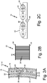
- FIG. 2A is a schematic illustration showing one configuration of heater system 18.
- first heater layer 22 and second heater layer 24 In between heater layer 22 and heater layer 24, is film adhesive and insulation 26. Film adhesive and insulation 26 is also used in between probe surface 16 and first heater layer 22 and between probe sleeve 20 and second heater layer 24. Film adhesive and insulation 26 help hold each heater layer (layers 22 and 24) in place within air data sensor 10. Film adhesive and insulation 26 further help insulate air data sensor 10.
- First heater layer 22 includes CNT heater 28 and first PTC heater 30.
- Second heater layer 24 includes second PTC heater 32. Because CNT heater 28 is made from carbon nanotube and silicone composite, CNT heater 28 is more rigid and durable than PTC heater 30 and PTC heater 32. Therefore, CNT heater 28 is in first heater layer 22 to protect first PTC heater 30 and second PTC heater 32.
- FIG. 2B is a schematic illustration showing first heater layer 22.
- First heater layer 22 includes positive terminal 34, negative terminal 36, PTC heater elements 38, and CNT heater elements 40.
- PTC heater elements 38 and CNT heater elements 40 extend from positive terminal 34 to negative terminal 36 and are interleaved with one another. As a result, PTC heater elements 38 and CNT heater elements 40 are connected physically and electrically in parallel to one another.
- FIG. 2C is a schematic diagram showing the configuration of heater system 18.
- Heater system 18 includes first heater set 42, second heater set 44, and voltage source 46.
- First heater set 42 includes CNT heater 28, first PTC heater 30, and second PTC heater 32.
- First CNT heater 28 and first PTC heater 30 are wired in parallel, forming first parallel formation 48.
- Second PTC heater 32 is wired in series between voltage source 46 and first parallel formation 48.
- First heater set 44 is installed within strut assembly 12 of air data sensor 10.
- the resistance of parallel formation 48 in first heater set 42 is less than each of the individual resistance of CNT heater 28 and first PTC heater 30. Therefore, parallel formation 48 ensures faster heating than CNT heater 28 would provide by itself.
- the resistance of second PTC heater 32 is selected so that the total resistance of second PTC heater 32 and parallel formation 48 is less than the resistance of CNT heater 28 at a set lower temperature (e.g., less than 20 °C).
- the resistance of second PTC heater 32 and parallel formation 48 is less than the resistance of CNT heater 28 at lower temperatures so that PTC heaters (30 and 34) do not impede CNT heater 28 at low temperatures.
- the resistance of second PTC heater 32 is further configured so that the resistance of second PTC heater 32 will increase to a maximum resistance at a set higher temperature, therefore the electrical resistivity of first PTC heater 30 and second PTC heater 32 do not need to be equal.
- the initial lower resistance of first heater set 42 when first heater set 42 is at a low temperature results in first heater set 42 rapidly heating strut assembly 12.
- the resistance of second PTC heater 32 increases to a maximum.
- second PTC heater 32 restricts the power input to first parallel formation 48. As a result of the power input being restricted to first parallel formation 48, first heater set 42 will not overheat and first heater set 42 will reduce the power consumption of heater system 18.
- First PTC heater 30 and second PTC 32 provide self-regulation of first heater set 42 and help mitigate either hot or cold spots on strut assembly 12.
- Second heater set 44 includes second CNT heater 50, third PTC heater 52, and fourth PTC heater 54.
- Third PTC heater 52 and second CNT heater 50 are wired in parallel, forming second parallel formation 56.
- Fourth PTC heater 54 is wired in series with voltage source 46 and second parallel formation 56.
- Second heater set 44 is within housing assembly 14 of air data sensor 10.
- the values of electrical resistance for second heater set 44 can be similar to the values discussed in relation to first heater set 42 above. In other embodiments, the values for the electrical resistance of second heater set 44 can be different than the values discussed in relation to first heater set. However, with different resistance values, the relationship of those values will be essentially the same as the relationship of the values in Table 1. For example, the resistance of parallel formation 56 in second heater set 44 is less than each of the individual resistance of second CNT heater 50 and third PTC heater 52. Therefore, second parallel formation 56 ensures faster heating than second CNT heater 50 would provide by itself.
- the resistance of fourth PTC heater 54 is selected so that the total resistance of fourth PTC heater 54 and second parallel formation 56 is less than the resistance of second CNT heater 50 at a lower temperature (e.g., less than 20 °C).
- the resistance of fourth PTC heater 54 and second parallel formation 56 is less than the resistance of second CNT heater 50 at lower temperatures so that PTC heaters (52 and 54) do not impede second CNT heater 50 at low temperatures.
- the resistance of fourth PTC heater 54 is further configured so that the resistance of fourth PTC heater 54 will increase to a maximum resistance at a set higher temperature.
- the initial lower resistance of second heater set 44 when second heater set 44 is at a low temperature results in second heater set 44 rapidly heating housing assembly 14. At a higher temperature, the resistance of fourth PTC heater 54 increases to a maximum.
- fourth PTC heater 54 When the resistance of fourth PTC heater 54 reaches a maximum, fourth PTC heater 54 restricts the power input to second parallel formation 56. As a result of the power input being restricted to second parallel formation 56, second heater set 44 will not overheat and second heater set 44 will reduce the power consumption of heating system 18. Third PTC heater 52 and fourth PTC 54 provide self-regulation of second heater set 44 and help mitigate either hot or cold spots on housing assembly 14.
- first heater set 42 and second heater set 44 are configured to have different resistances to ensure they adequately heat strut assembly 12 and housing assembly 14, respectively.
- first heater set 42 and second heater set 44 can be identical and provide equal heating to strut assembly 12 and housing assembly 14, respectively.
- first heater set 42 can be located within strut assembly 12 and second heater set 44 can be located within housing assembly 14.
- first heater set 42 and second heater set 44 can be wired in series with one another and voltage source 46.
- first heater set 42 is located within strut assembly 12 and second heater set 44 is located within housing assembly 14, first heater set 42 and second heater set 44 each heating system can have dedicated voltage sources, and each system (first heater set 42 and second heater set 44) can be a standalone system independent of one another.
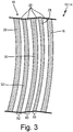
- FIG. 3 is a schematic diagram of an alternative configuration of the heater system 18.
- heater system 18 includes third heater layer 58, fourth heater layer 60, and fifth heater layer 62.
- Film adhesive and insulation 26 is found between each of the heater layers (58, 60, and 62), between probe surface 16 and third heater layer 58, and between probe sleeve 20 and fifth heater layer 62.
- Third heater layer 58 includes CNT heater 28.
- Fourth heater layer 60 includes PTC heater 30.
- Fifth heater layer 62 includes PTC heater 32.
- Third heater layer 58 and fourth heater layer 60 are wired in parallel to form parallel formation 48 (as shown in FIG. 2C ).
- Fifth heater layer 62 is wired in series with voltage source 46 and parallel formation 48.
- CNT heater 28 is made from carbon nanotube and silicone composite, CNT heater 28 is more rigid and durable than PTC heater 30 and PTC heater 32. Therefore, in the configuration of heater system 18, CNT heater 28 should be in the outermost heater layer (e.g., third heater layer 58) so that CNT heater 28 can protected fourth heater layer 60 and fifth heater layer 62.
- first heater set 42 (as shown in FIG. 2C ) can be located within strut assembly 12 and second heater set 44 (as shown in FIG. 2C ) can be located within housing assembly 14.
- first heater set 42 and second heater set 44 can be wired in series with one another and voltage source 46.
- first heater set 42 is located within strut assembly 12 and second heater set 44 is located within housing assembly 14
- first heater set 42 and second heater set 44 each heating system can have dedicated voltage sources, and each system (first heater set 42 and second heater set 44) can be a standalone system independent of one another.
- FIGS. 4A and 4B will be discussed concurrently.
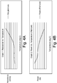
- FIG. 4A is a graph showing resistance as a function of temperature for heater system 18.
- FIG. 4B is a graph showing power as a function of temperature heater system 18.
- the graphs in FIGS 4A and 4B show the relationship discussed above in paragraphs [0024] and [0026] above.
- the resistance of the heater system is low when the temperature of the heater system is low.
- the resistance of the heater system increases as the temperature of the heater system increases.
- the power supplied to the overall heating system decreases as the temperature increases. Decreasing the power to the heating system prevents the heating system from overheating and conserves energy.
- a hybrid heater system for an aircraft air data sensor includes a voltage source and a first hybrid heater set.
- the first hybrid heater set includes a carbon nanotube (CNT) heater, a first positive temperature coefficient (PTC) heater disposed in parallel with the CNT heater to form a parallel formation, and a second PTC heater disposed in series between the voltage source and the parallel formation.
- CNT carbon nanotube
- PTC positive temperature coefficient
- hybrid heater system of the preceding paragraph can optionally include, additionally and/or alternatively, any one or more of the following features, configurations and/or additional components:
- a hybrid heater system for ice protection of an air data probe on an aircraft includes a voltage source, a carbon nanotube (CNT) heater, which includes CNT heater elements, a first positive temperature coefficient (PTC) heater disposed in parallel with the CNT heater to form a parallel formation, and a second PTC heater.
- the first PTC heater includes first PTC heater elements interleaved with the CNT heater elements in a first air data probe layer.
- the second PTC heater is disposed in a second air data probe layer and in series between the voltage source and the parallel formation.
- hybrid heater system of the preceding paragraph can optionally include, additionally and/or alternatively, any one or more of the following features, configurations and/or additional components:
- a method of making a heater for an air data probe includes positioning on the air data probe a first heater layer.
- the first heater layer includes a carbon nanotube (CNT) heater element and a first positive temperature coefficient (PTC) heater element interleaved with one another.
- the method of heating an air data probe further includes positioning on the air data probe a second heater layer.
- the second heater layer includes a second PTC heater element.
- the method of heating an air data probe further includes wiring the first heater layer and the second heater layer so that the CNT heater element and the first PTC heater element are in parallel with one another defining a parallel formation.
- the method of heating an air data probe further includes wiring the second heater layer so that the second PTC heater element is in series with the first parallel formation and a voltage source.
- the method of the preceding paragraph can optionally include, additionally and/or alternatively, any one or more of the following features, configurations and/or additional components:
Landscapes
- Engineering & Computer Science (AREA)
- Aviation & Aerospace Engineering (AREA)
- Physics & Mathematics (AREA)
- General Physics & Mathematics (AREA)
- Resistance Heating (AREA)
- Thermistors And Varistors (AREA)
Abstract
Description
- The following description relates to air data sensors, and more specifically, to heater systems for aircraft air data sensors.
- Ice accretion on aircraft air data sensors can render the air data sensors inoperable for their intended purpose. Heaters are implemented to prevent ice accretion or melt ice that has already accreted on air data sensors. Typically, nichrome-based metal alloy resistance heaters are used to heat air data sensors. However, nichrome-based metal alloy resistance heaters result in high power consumption without high heating capacity.
- In one embodiment, a hybrid heater system for an aircraft air data sensor includes a voltage source and a first hybrid heater set. The first hybrid heater set includes a carbon nanotube (CNT) heater, a first positive temperature coefficient (PTC) heater disposed in parallel with the CNT heater to form a parallel formation, and a second PTC heater disposed in series between the voltage source and the parallel formation.
- In another embodiment, a hybrid heater system for ice protection of an air data probe on an aircraft includes a voltage source, a carbon nanotube (CNT) heater, which includes CNT heater elements, a first positive temperature coefficient (PTC) heater disposed in parallel with the CNT heater to form a parallel formation, and a second PTC heater. The first PTC heater includes first PTC heater elements interleaved with the CNT heater elements in a first air data probe layer. The second PTC heater is disposed in a second air data probe layer and in series between the voltage source and the parallel formation.
- In another embodiment, a method of making a heater for an air data probe includes positioning on the air data probe a first heater layer. The first heater layer includes a carbon nanotube (CNT) heater element and a first positive temperature coefficient (PTC) heater element interleaved with one another. The method of heating an air data probe further includes positioning on the air data probe a second heater layer. The second heater layer includes a second PTC heater element. The method of heating an air data probe further includes wiring the first heater layer and the second heater layer so that the CNT heater element and the first PTC heater element are in parallel with one another defining a parallel formation. The method of heating an air data probe further includes wiring the second heater layer so that the second PTC heater element is in series with the first parallel formation and a voltage source.
-
-
FIG. 1A is a perspective view of an air data sensor. -
FIG. 1B is a side view of an air data sensor. -
FIG. 1C is a zoomed-in cross-sectional view taken along line A-A inFIG. 1B of an air data sensor. -
FIG. 2A is a schematic illustration showing one configuration of the hybrid heater system. -
FIG. 2B is a schematic illustration showing hybrid heater elements. -
FIG. 2C is a schematic illustration showing the configuration of a hybrid heater system in the strut assembly and a hybrid heater system in the housing assembly in series with one another and a voltage source. -
FIG. 3 is a schematic view showing another configuration of the hybrid heater system. -
FIG. 4A is a graph showing resistance as a function of temperature for a hybrid heater system. -
FIG. 4B is a graph showing power as a function of temperature for a hybrid heater system. - While the above-identified drawing figures set forth one or more embodiments, other embodiments are contemplated. It should be understood that numerous other modifications and embodiments can be devised by those skilled in the art, which fall within the scope and spirit of the principles of the claims. The figures may not be drawn to scale, and applications and embodiments may include features and components not specifically shown in the drawings. Like reference numerals identify similar structural elements.
- The present disclosure relates to air data probes with hybrid heater systems using carbon nanotube (CNT) heaters and positive temperature coefficient (PTC) heaters. CNT heaters are made with carbon nanotube and a silicone composite. CNT heaters have a negative temperature coefficient (NTC) at low temperatures. Because CNT heaters have an NTC at low temperatures, the electrical resistance of CNT heaters is higher at low temperatures and drops drastically and stabilizes at a lower resistance level at higher temperatures. The NTC of CNT heaters makes CNT heaters great for quickly heating a device or mechanism. However, because CNT heaters have an NTC, there is no regulating mechanism at higher temperatures unless they are installed with temperature sensor feedback systems. PTC heaters increase in electrical resistance as temperature increases. As a result of the increased resistance with the increased temperature, PTC heaters self-regulate the temperatures at a pre-defined higher temperature. The hybrid heater system is a self-regulating heater system using CNT and PTC heaters. The hybrid heater system for air data probes will be described below with reference to
FIGS 1A-4B . -
FIGS 1A-1C will be discussed concurrently.FIG. 1A is a perspective view ofair data sensor 10.FIG. 1B is a side view ofair data sensor 10.FIG. 1C is a zoomed-in cross-sectional view taken along line A-A inFIG. 1B ofair data sensor 10.Air data sensor 10 includesstrut assembly 12 andhousing assembly 14.Housing assembly 14 includesprobe surface 16, hybrid thin-film heater system 18 ("heater system 18"), andprobe sleeve 20. In the present embodiment,air data sensor 10 is a pitot-tube air data sensor. In another embodiment,air data sensor 10 can be a pitot-static probe, multi-function probe with flow angle measurement, and/or any other air data sensor used on an aircraft. -
Strut assembly 12 attaches to an airplane (not shown) and extends radially outward from the airplane.Housing assembly 14 is tubular in shape and extends fromstrut assembly 12.Housing assembly 14 is generally parallel to the surface of the airplane.Sleeve 20 is withinhousing assembly 14 and guides airflow intoair data sensor 10. - To prevent ice accretion and melt ice accretion within and on the exterior surface of
air data sensor 10,heater system 18 can be installed withinstrut assembly 12 andhousing assembly 14. As shown inFIG. 1C ,heater system 18 is installed withinhousing assembly 14 betweenprobe surface 16 andprobe sleeve 20. Probesurface 16 is the exterior shell ofair data sensor 10 and helps protectair data sensor 10 andheater system 18. Air flows intoair data sensor 10 throughprobe sleeve 20. Probesleeve 20 helps protectair data sensor 10 andheater system 18.Heater system 18 can effectively heatprobe surface 16 andprobe sleeve 20 to prevent ice accretion thereon. In the present embodiment,heater system 18 is installed withinair data sensor 10. In another embodiment,heater system 18 can be installed on the exterior ofair data sensor 10. -
FIG. 2A is a schematic illustration showing one configuration ofheater system 18. In the embodiment ofFIG. 2A , there are two heater layers,first heater layer 22 andsecond heater layer 24. In betweenheater layer 22 andheater layer 24, is film adhesive andinsulation 26. Film adhesive andinsulation 26 is also used in betweenprobe surface 16 andfirst heater layer 22 and betweenprobe sleeve 20 andsecond heater layer 24. Film adhesive andinsulation 26 help hold each heater layer (layers 22 and 24) in place withinair data sensor 10. Film adhesive andinsulation 26 further help insulateair data sensor 10.First heater layer 22 includesCNT heater 28 andfirst PTC heater 30.Second heater layer 24 includessecond PTC heater 32. BecauseCNT heater 28 is made from carbon nanotube and silicone composite,CNT heater 28 is more rigid and durable thanPTC heater 30 andPTC heater 32. Therefore,CNT heater 28 is infirst heater layer 22 to protectfirst PTC heater 30 andsecond PTC heater 32. -
FIG. 2B is a schematic illustration showingfirst heater layer 22.First heater layer 22 includespositive terminal 34,negative terminal 36, PTC heater elements 38, andCNT heater elements 40. Infirst heater layer 22, PTC heater elements 38 andCNT heater elements 40 extend from positive terminal 34 tonegative terminal 36 and are interleaved with one another. As a result, PTC heater elements 38 andCNT heater elements 40 are connected physically and electrically in parallel to one another. -
FIG. 2C is a schematic diagram showing the configuration ofheater system 18.Heater system 18 includes first heater set 42, second heater set 44, andvoltage source 46. First heater set 42 includesCNT heater 28,first PTC heater 30, andsecond PTC heater 32. -
First CNT heater 28 andfirst PTC heater 30 are wired in parallel, forming firstparallel formation 48.Second PTC heater 32 is wired in series betweenvoltage source 46 and firstparallel formation 48. First heater set 44 is installed withinstrut assembly 12 ofair data sensor 10. - The resistance of
parallel formation 48 in first heater set 42 is less than each of the individual resistance ofCNT heater 28 andfirst PTC heater 30. Therefore,parallel formation 48 ensures faster heating thanCNT heater 28 would provide by itself. The resistance ofsecond PTC heater 32 is selected so that the total resistance ofsecond PTC heater 32 andparallel formation 48 is less than the resistance ofCNT heater 28 at a set lower temperature (e.g., less than 20 °C). The resistance ofsecond PTC heater 32 andparallel formation 48 is less than the resistance ofCNT heater 28 at lower temperatures so that PTC heaters (30 and 34) do not impedeCNT heater 28 at low temperatures. The resistance ofsecond PTC heater 32 is further configured so that the resistance ofsecond PTC heater 32 will increase to a maximum resistance at a set higher temperature, therefore the electrical resistivity offirst PTC heater 30 andsecond PTC heater 32 do not need to be equal. The initial lower resistance of first heater set 42 when first heater set 42 is at a low temperature results in first heater set 42 rapidly heatingstrut assembly 12. At a higher temperature, the resistance ofsecond PTC heater 32 increases to a maximum. When the resistance ofsecond PTC heater 32 reaches a maximum,second PTC heater 32 restricts the power input to firstparallel formation 48. As a result of the power input being restricted to firstparallel formation 48, first heater set 42 will not overheat and first heater set 42 will reduce the power consumption ofheater system 18.First PTC heater 30 andsecond PTC 32 provide self-regulation of first heater set 42 and help mitigate either hot or cold spots onstrut assembly 12. - Second heater set 44 includes
second CNT heater 50,third PTC heater 52, andfourth PTC heater 54.Third PTC heater 52 andsecond CNT heater 50 are wired in parallel, forming secondparallel formation 56.Fourth PTC heater 54 is wired in series withvoltage source 46 and secondparallel formation 56. Second heater set 44 is withinhousing assembly 14 ofair data sensor 10. - In the present embodiment, the values of electrical resistance for second heater set 44 can be similar to the values discussed in relation to first heater set 42 above. In other embodiments, the values for the electrical resistance of second heater set 44 can be different than the values discussed in relation to first heater set. However, with different resistance values, the relationship of those values will be essentially the same as the relationship of the values in Table 1. For example, the resistance of
parallel formation 56 in second heater set 44 is less than each of the individual resistance ofsecond CNT heater 50 andthird PTC heater 52. Therefore, secondparallel formation 56 ensures faster heating thansecond CNT heater 50 would provide by itself. The resistance offourth PTC heater 54 is selected so that the total resistance offourth PTC heater 54 and secondparallel formation 56 is less than the resistance ofsecond CNT heater 50 at a lower temperature (e.g., less than 20 °C). The resistance offourth PTC heater 54 and secondparallel formation 56 is less than the resistance ofsecond CNT heater 50 at lower temperatures so that PTC heaters (52 and 54) do not impedesecond CNT heater 50 at low temperatures. The resistance offourth PTC heater 54 is further configured so that the resistance offourth PTC heater 54 will increase to a maximum resistance at a set higher temperature. The initial lower resistance of second heater set 44 when second heater set 44 is at a low temperature results in second heater set 44 rapidly heatinghousing assembly 14. At a higher temperature, the resistance offourth PTC heater 54 increases to a maximum. When the resistance offourth PTC heater 54 reaches a maximum,fourth PTC heater 54 restricts the power input to secondparallel formation 56. As a result of the power input being restricted to secondparallel formation 56, second heater set 44 will not overheat and second heater set 44 will reduce the power consumption ofheating system 18.Third PTC heater 52 andfourth PTC 54 provide self-regulation of second heater set 44 and help mitigate either hot or cold spots onhousing assembly 14. - In the present embodiment, first heater set 42 and second heater set 44 are configured to have different resistances to ensure they adequately heat
strut assembly 12 andhousing assembly 14, respectively. In another embodiment, first heater set 42 and second heater set 44 can be identical and provide equal heating to strutassembly 12 andhousing assembly 14, respectively. - In the present embodiment, first heater set 42 can be located within
strut assembly 12 and second heater set 44 can be located withinhousing assembly 14. When first heater set 42 is located withinstrut assembly 12 and second heater set 44 is located withinhousing assembly 14, first heater set 42 and second heater set 44 can be wired in series with one another andvoltage source 46. In another embodiment, first heater set 42 is located withinstrut assembly 12 and second heater set 44 is located withinhousing assembly 14, first heater set 42 and second heater set 44 each heating system can have dedicated voltage sources, and each system (first heater set 42 and second heater set 44) can be a standalone system independent of one another. -
FIG. 3 is a schematic diagram of an alternative configuration of theheater system 18. In the embodiment ofFIG. 3 ,heater system 18 includes third heater layer 58,fourth heater layer 60, andfifth heater layer 62. Film adhesive andinsulation 26 is found between each of the heater layers (58, 60, and 62), betweenprobe surface 16 and third heater layer 58, and betweenprobe sleeve 20 andfifth heater layer 62. Third heater layer 58 includesCNT heater 28.Fourth heater layer 60 includesPTC heater 30.Fifth heater layer 62 includesPTC heater 32. Third heater layer 58 andfourth heater layer 60 are wired in parallel to form parallel formation 48 (as shown inFIG. 2C ).Fifth heater layer 62 is wired in series withvoltage source 46 andparallel formation 48. BecauseCNT heater 28 is made from carbon nanotube and silicone composite,CNT heater 28 is more rigid and durable thanPTC heater 30 andPTC heater 32. Therefore, in the configuration ofheater system 18,CNT heater 28 should be in the outermost heater layer (e.g., third heater layer 58) so thatCNT heater 28 can protectedfourth heater layer 60 andfifth heater layer 62. - In the present embodiment of
FIG. 3 , first heater set 42 (as shown inFIG. 2C ) can be located withinstrut assembly 12 and second heater set 44 (as shown inFIG. 2C ) can be located withinhousing assembly 14. When first heater set 42 is located withinstrut assembly 12 and second heater set 44 is located withinhousing assembly 14, first heater set 42 and second heater set 44 can be wired in series with one another andvoltage source 46. In another embodiment, first heater set 42 is located withinstrut assembly 12 and second heater set 44 is located withinhousing assembly 14, first heater set 42 and second heater set 44 each heating system can have dedicated voltage sources, and each system (first heater set 42 and second heater set 44) can be a standalone system independent of one another. -
FIGS. 4A and 4B will be discussed concurrently.FIG. 4A is a graph showing resistance as a function of temperature forheater system 18.FIG. 4B is a graph showing power as a function oftemperature heater system 18. The graphs inFIGS 4A and 4B show the relationship discussed above in paragraphs [0024] and [0026] above. In general, because of the configuration of the PTC heater in series with the parallel formation (comprised of another PTC heater and a CNT heater) the resistance of the heater system is low when the temperature of the heater system is low. The resistance of the heater system increases as the temperature of the heater system increases. As a result of the increasing resistance, the power supplied to the overall heating system decreases as the temperature increases. Decreasing the power to the heating system prevents the heating system from overheating and conserves energy. - The following are non-exclusive descriptions of possible embodiments of the present invention.
- In one embodiment, a hybrid heater system for an aircraft air data sensor includes a voltage source and a first hybrid heater set. The first hybrid heater set includes a carbon nanotube (CNT) heater, a first positive temperature coefficient (PTC) heater disposed in parallel with the CNT heater to form a parallel formation, and a second PTC heater disposed in series between the voltage source and the parallel formation.
- The hybrid heater system of the preceding paragraph can optionally include, additionally and/or alternatively, any one or more of the following features, configurations and/or additional components:
- wherein an electrical resistance of the second PTC heater is greater than an electrical resistance of the parallel formation at a temperature greater than a set temperature, and wherein the electrical resistance of the second PTC heater is less than the electrical resistance of the parallel formation at a temperature less than the set temperature;
- wherein the first PTC heater and the second PTC heater have differing electrical resistivity;
- wherein an effective electrical resistance of the first parallel formation is less than an electrical resistance of each of the CNT heater and the first PTC heater;
- further including an air data sensor that includes a strut assembly, a housing assembly, extending from the strut assembly, a second heater set including a second CNT heater, a third PTC heater disposed in parallel with the second CNT heater to form a second parallel formation; and a fourth PTC heater disposed in series between the voltage source and the second parallel formation, wherein the first hybrid heater set is within the strut assembly, and the second hybrid heater set is within the housing assembly, and wherein the first hybrid heater set and the second hybrid heater set are electrically connected in series;
- the CNT heater and the first PTC heater occupy a same layer in the air data sensor, and the same layer occupied by the CNT heater and the first PTC heater includes a first terminal, a second terminal, a first PTC heater elements extending between the first and second terminals, and CNT heater elements interleaved between the first PTC heater elements and extending between the first and second terminals;
- wherein the air data probe includes an outermost probe surface, a first film adhesive and insulation layer underlying the outermost probe surface, a first heater layer underlying the first film adhesive and insulation layer, the first heater layer includes CNT heater elements of the CNT heater and first PTC heater elements of the first PTC heater, a second film adhesive and insulation layer underlying the first heater layer, a second heater layer underlying the second film adhesive and insulation layer, the second heater layer includes a second PTC heater, a third film adhesive and insulation layer underlying the second heater layer, and a sleeve surface underlying the third film adhesive and insulation layer;
- wherein the CNT and the first PTC heater occupy different layers in the air data sensor; and/or
- wherein the air data probe includes an outermost probe surface, a first film adhesive and insulation layer underlying the outermost probe surface, a first heater layer underlying the first film adhesive and insulation layer, the first heater layer includes the CNT heater, a second film adhesive and insulation layer underlying the first heater layer, a second heater layer underlying the second adhesive and insulation layer, the second heater layer includes one of the first or second PTC heaters, a third film adhesive and insulation layer underlying the second heater layer, the third heater layer includes the other of the first or second PTC heaters, a fourth film adhesive and insulation layer underlying the third heater layer, and a sleeve surface underlying the fourth film and insulation layer.
- In another embodiment, a hybrid heater system for ice protection of an air data probe on an aircraft includes a voltage source, a carbon nanotube (CNT) heater, which includes CNT heater elements, a first positive temperature coefficient (PTC) heater disposed in parallel with the CNT heater to form a parallel formation, and a second PTC heater. The first PTC heater includes first PTC heater elements interleaved with the CNT heater elements in a first air data probe layer. The second PTC heater is disposed in a second air data probe layer and in series between the voltage source and the parallel formation.
- The hybrid heater system of the preceding paragraph can optionally include, additionally and/or alternatively, any one or more of the following features, configurations and/or additional components:
- wherein the second PTC heater establishes the maximum temperature capability for ice protection, and the hybrid heater system operates with an absence of active temperature controls;
- wherein the first PTC heater and the second PTC heater have different electrical resistivity;
- wherein an effective electrical resistance of the first parallel formation is less than an electrical resistance of each of the CNT heater and the first PTC heater;
- wherein the air data probe layer includes first and second terminals between which the interleaved CNT and first PTC heater elements extend; and/or
- wherein the second air data probe layer underlies the first air data probe layer.
- In another embodiment, a method of making a heater for an air data probe includes positioning on the air data probe a first heater layer. The first heater layer includes a carbon nanotube (CNT) heater element and a first positive temperature coefficient (PTC) heater element interleaved with one another. The method of heating an air data probe further includes positioning on the air data probe a second heater layer. The second heater layer includes a second PTC heater element. The method of heating an air data probe further includes wiring the first heater layer and the second heater layer so that the CNT heater element and the first PTC heater element are in parallel with one another defining a parallel formation. The method of heating an air data probe further includes wiring the second heater layer so that the second PTC heater element is in series with the first parallel formation and a voltage source.
- The method of the preceding paragraph can optionally include, additionally and/or alternatively, any one or more of the following features, configurations and/or additional components:
- wherein the second PTC heater element establishes a maximum temperature capability for ice protection, and the hybrid heater system operates with an absence of active temperature controls;
- wherein the first PTC heater element and the second PTC heater element have differing electrical resistivity;
- wherein an effective electrical resistance of the parallel formation is less than an electrical resistance of each of the CNT heater element and the first PTC heater element; and/or
- wherein the first heater layer is split between two heater layers and includes a layer of film adhesive and insulation therebetween.
- While the invention has been described with reference to an exemplary embodiment(s), it will be understood by those skilled in the art that various changes may be made and equivalents may be substituted for elements thereof without departing from the scope of the invention. In addition, many modifications may be made to adapt a particular situation or material to the teachings of the invention without departing from the essential scope thereof. Therefore, it is intended that the invention not be limited to the particular embodiment(s) disclosed, but that the invention will include all embodiments falling within the scope of the appended claims.
Claims (15)
- A hybrid heater system for an aircraft air data sensor, the hybrid heater system comprising;
a voltage source (46);
a first hybrid heater set (42);a carbon nanotube "CNT" heater (28);a first positive temperature coefficient "PTC" heater disposed in parallel with the CNT heater to form a parallel formation; anda second PTC heater disposed in series between the voltage source and the parallel formation. - The hybrid heater of claim 1, wherein an electrical resistance of the second PTC heater is greater than an electrical resistance of the parallel formation at a temperature greater than a set temperature, and wherein the electrical resistance of the second PTC heater is less than the electrical resistance of the parallel formation at a temperature less than the set temperature.
- The hybrid heater system of claim 1 or 2, further comprising an air data sensor comprising:a strut assembly;a tubular housing assembly, extending from the strut assembly;a second heater set comprising:a second CNT heater;a third PTC heater disposed in parallel with the second CNT heater to form a second parallel formation; anda fourth PTC heater disposed in series between the voltage source and the second parallel formation, wherein the first hybrid heater set is within the strut assembly, and the second hybrid heater set is within the housing assembly, and wherein the first hybrid heater set and the second hybrid heater set are electrically connected in series.
- The hybrid heater system of claim 3, wherein:
the CNT heater and the first PTC heater occupy a same layer in the air data sensor, and the same layer occupied by the CNT heater and the first PTC heater comprises:a first terminal;a second terminal;first PTC heater elements extending between the first and second terminals; andCNT heater elements interleaved between the first PTC heater elements and extending between the first and second terminals, and/or wherein the air data probe comprises:an outermost probe surface;a first film adhesive and insulation layer underlying the outermost probe surface;a first heater layer underlying the first film adhesive and insulation layer, the first heater layer comprising CNT heater elements of the CNT heater and first PTC heater elements of the first PTC heater;a second film adhesive and insulation layer underlying the first heater layer;a second heater layer underlying the second film adhesive and insulation layer, the second heater layer comprising a second PTC heater;a third film adhesive and insulation layer underlying the second heater layer; anda sleeve surface underlying the third film adhesive and insulation layer. - The hybrid heater system of claim 3, wherein the CNT heater and the first PTC heater occupy different layers in the air data sensor.
- The hybrid heater system of claim 3, wherein the air data probe comprises:an outermost probe surface;a first film adhesive and insulation layer underlying the outermost probe surface;a first heater layer underlying the first film adhesive and insulation layer, the first heater layer comprising the CNT heater.a second film adhesive and insulation layer underlying the first heater layer;a second heater layer underlying the second film adhesive and insulation layer, the second heater layer comprising one of the first or second PTC heaters;a third film adhesive and insulation layer underlying the second heater layer;a third heater layer underlying the third film adhesive and insulation layer, the third heater layer comprising the other of the first or second PTC heaters;a fourth film adhesive and insulation layer underlying the third heater layer; anda sleeve surface underlying the fourth film adhesive and insulation layer.
- A hybrid heater system for ice protection of an air data probe on an aircraft, the hybrid heater system comprising:a voltage source (46);a carbon nanotube "CNT" heater (28) comprising CNT heater elements;a first positive temperature coefficient "PTC" heater disposed in parallel with the CNT heater to form a parallel formation, wherein the first PTC heater comprises first PTC heater elements interleaved with the CNT heater elements in a first air data probe layer; anda second PTC heater disposed in a second air data probe layer and in series between the voltage source and the parallel formation.
- The hybrid heater system of claim 7, wherein the second PTC heater establishes the maximum temperature capability for ice protection, and the hybrid heater system operates with an absence of active temperature controls.
- The hybrid heater system of any preceding claim, wherein the first PTC heater and the second PTC heater have differing electrical resistivity.
- The heater system of any preceding claim, wherein an effective electrical resistance of the first parallel formation is less than an electrical resistance of each of the CNT heater and the first PTC heater.
- The hybrid heater system of any of claims 7 to 10, wherein the first air data probe layer comprises first and second terminals between which the interleaved CNT and first PTC heater elements extend.
- The hybrid heater system according to any of claims 7 to 11, wherein the second air data probe layer underlies the first air data probe layer.
- A method of making a heater for an air data probe comprising:positioning on the air data probe a first heater layer comprising a carbon nanotube "CNT" heater element (28) and a first positive temperature coefficient "PTC" heater element interleaved with one another;positioning on the air data probe a second heater layer comprising a second PTC heater element;wiring the first heater layer and the second heater layer so that the CNT heater element and the first PTC heater element are in parallel with one another defining a parallel formation; andwiring the second heater layer so that the second PTC heater element is in series with the first parallel formation and a voltage source.
- The method of claim 13, wherein the second PTC heater element establishes a maximum temperature capability for ice protection, and the hybrid heater system operates with an absence of active temperature controls.
- The method of claim 13 or 14, wherein the first PTC heater element and the second PTC heater element have differing electrical resistivity,
and/or wherein an effective electrical resistance of the parallel formation is less than an electrical resistance of each of the CNT heater element and the first PTC heater element,
and/or wherein the first heater layer is split between two heater layers and comprises a layer of film adhesive and insulation therebetween.
Applications Claiming Priority (1)
| Application Number | Priority Date | Filing Date | Title |
|---|---|---|---|
| IN202041012145 | 2020-03-20 |
Publications (2)
| Publication Number | Publication Date |
|---|---|
| EP3883337A1 true EP3883337A1 (en) | 2021-09-22 |
| EP3883337B1 EP3883337B1 (en) | 2025-12-10 |
Family
ID=75108237
Family Applications (1)
| Application Number | Title | Priority Date | Filing Date |
|---|---|---|---|
| EP21163469.6A Active EP3883337B1 (en) | 2020-03-20 | 2021-03-18 | Thin film heater configuration for air data probe |
Country Status (4)
| Country | Link |
|---|---|
| US (1) | US11745879B2 (en) |
| EP (1) | EP3883337B1 (en) |
| BR (1) | BR102021001713A2 (en) |
| CA (1) | CA3109793A1 (en) |
Families Citing this family (3)
| Publication number | Priority date | Publication date | Assignee | Title |
|---|---|---|---|---|
| US11425797B2 (en) * | 2019-10-29 | 2022-08-23 | Rosemount Aerospace Inc. | Air data probe including self-regulating thin film heater |
| US11745879B2 (en) | 2020-03-20 | 2023-09-05 | Rosemount Aerospace Inc. | Thin film heater configuration for air data probe |
| FR3165241A1 (en) * | 2024-08-02 | 2026-02-06 | Thales | Aerodynamic measuring device |
Citations (2)
| Publication number | Priority date | Publication date | Assignee | Title |
|---|---|---|---|---|
| US4458137A (en) * | 1981-04-09 | 1984-07-03 | Rosemount Inc. | Electric heater arrangement for fluid flow stream sensors |
| US20200086999A1 (en) * | 2018-09-13 | 2020-03-19 | Goodrich Corporation | Hybrid heater for aircraft wing ice protection |
Family Cites Families (58)
| Publication number | Priority date | Publication date | Assignee | Title |
|---|---|---|---|---|
| US2254155A (en) | 1938-12-13 | 1941-08-26 | Bendix Aviat Corp | Pitot-static tube |
| US4121088A (en) | 1976-10-18 | 1978-10-17 | Rosemount Inc. | Electrically heated air data sensing device |
| GB8604519D0 (en) | 1986-02-24 | 1986-04-03 | Raychem Sa Nv | Electrical devices |
| FR2695203B1 (en) | 1992-08-28 | 1994-11-04 | Intertechnique Sa | Thermistor liquid detector. |
| US5543183A (en) | 1995-02-17 | 1996-08-06 | General Atomics | Chromium surface treatment of nickel-based substrates |
| JPH09163593A (en) * | 1995-12-05 | 1997-06-20 | Murata Mfg Co Ltd | Inrush current suppression circuit |
| US6070475A (en) | 1997-10-15 | 2000-06-06 | Rosemont Aerospace Inc. | Air data probe with heater means within wall |
| EP1186206B1 (en) | 1999-05-14 | 2008-12-10 | Asuk Technologies, LLC | Electrical heating devices and resettable fuses |
| US6591696B2 (en) | 2001-07-12 | 2003-07-15 | Rosemount Aerospace, Inc. | Integral electric pressure probe for aircraft |
| GB0427650D0 (en) | 2004-12-17 | 2005-01-19 | Heat Trace Ltd | Electrical device |
| GB0428297D0 (en) | 2004-12-24 | 2005-01-26 | Heat Trace Ltd | Control of heating cable |
| KR100749886B1 (en) | 2006-02-03 | 2007-08-21 | (주) 나노텍 | Heating element using carbon nanotube |
| US7923668B2 (en) | 2006-02-24 | 2011-04-12 | Rohr, Inc. | Acoustic nacelle inlet lip having composite construction and an integral electric ice protection heater disposed therein |
| GB0609729D0 (en) | 2006-05-17 | 2006-06-28 | Heat Trace Ltd | Material and heating cable |
| KR100973593B1 (en) | 2006-06-27 | 2010-08-03 | 앤에이오에스 주식회사 | Method for producing planar heating element using carbon microfiber and Planar heating element using carbon microfiber |
| WO2008085550A2 (en) | 2006-08-02 | 2008-07-17 | Battelle Memorial Institute | Electrically conductive coating composition |
| SE530660C2 (en) | 2006-10-17 | 2008-08-05 | Conflux Ab | Positive temperature coefficient superimposed impedance polymeric compound used in heating elements comprises electrically insulating matrix with amorphous polymer and two electrically conductive particles having different surface energies |
| US20080166563A1 (en) | 2007-01-04 | 2008-07-10 | Goodrich Corporation | Electrothermal heater made from thermally conducting electrically insulating polymer material |
| GB0700079D0 (en) | 2007-01-04 | 2007-02-07 | Boardman Jeffrey | A method of producing electrical resistance elements whihc have self-regulating power output characteristics by virtue of their configuration and the material |
| US20100116806A1 (en) | 2007-05-08 | 2010-05-13 | Honeywell International Inc. | Automated heating system for ports susceptible to icing |
| US8164035B2 (en) | 2008-04-17 | 2012-04-24 | Long-Huang Chang | Heating device having dual-core heating cable |
| US20100126985A1 (en) | 2008-06-13 | 2010-05-27 | Tsinghua University | Carbon nanotube heater |
| AT508327A1 (en) | 2008-07-29 | 2010-12-15 | Villinger Markus | HEATING DEVICE FOR DEPARTING AIRCRAFT PARTS |
| GB0817082D0 (en) | 2008-09-18 | 2008-10-29 | Heat Trace Ltd | Heating cable |
| KR101328353B1 (en) | 2009-02-17 | 2013-11-11 | (주)엘지하우시스 | Heating sheet using carbon nano tube |
| BRPI1014711A2 (en) | 2009-04-27 | 2016-04-12 | Applied Nanostrctured Solutions Llc | cnt-based resistance heating to defrost composite structures |
| DE102009034306B4 (en) | 2009-07-21 | 2015-07-23 | Fraunhofer-Gesellschaft zur Förderung der angewandten Forschung e.V. | Heating element and method for its production |
| US8496854B2 (en) | 2009-10-30 | 2013-07-30 | Sabic Innovative Plastics Ip B.V. | Positive temperature coefficient materials with reduced negative temperature coefficient effect |
| US9091657B2 (en) | 2010-01-26 | 2015-07-28 | Metis Design Corporation | Multifunctional CNT-engineered structures |
| US8481898B2 (en) * | 2010-06-04 | 2013-07-09 | Robert Parker | Self regulating electric heaters |
| EP2641451B1 (en) | 2010-11-17 | 2019-03-06 | Battelle Memorial Institute | Carbon nanotube thin film laminate resistive heater |
| KR101184780B1 (en) | 2010-12-20 | 2012-09-20 | 한국항공우주연구원 | Fabrication of deicing pitot-static probe using lamination method |
| EP2658777B1 (en) | 2010-12-31 | 2019-07-03 | Battelle Memorial Institute | Anti-icing, de-icing, and heating configuration, integration, and power methods for aircraft, aerodynamic and complex surfaces |
| DE102011119844A1 (en) * | 2011-05-26 | 2012-12-13 | Eads Deutschland Gmbh | Composite structure with ice protection device and manufacturing process |
| CA2813551C (en) | 2012-04-20 | 2018-10-30 | Goodrich Corporation | Printed heating element |
| WO2014188191A1 (en) | 2013-05-21 | 2014-11-27 | Heat Trace Limited | Electrical heater |
| US9884685B2 (en) | 2014-05-28 | 2018-02-06 | The Boeing Company | External case heater for an angle of attack sensor |
| US10373745B2 (en) | 2014-06-12 | 2019-08-06 | LMS Consulting Group | Electrically conductive PTC ink with double switching temperatures and applications thereof in flexible double-switching heaters |
| KR101602880B1 (en) | 2014-06-18 | 2016-03-11 | (주)유니플라텍 | Positive temperature coefficient using conductive liquid emulsion polymer composition, manufacturing method of thereoff, Face heater with it |
| US10440829B2 (en) | 2014-07-03 | 2019-10-08 | United Technologies Corporation | Heating circuit assembly and method of manufacture |
| US11542018B2 (en) | 2015-01-06 | 2023-01-03 | Battelle Memorial Institute | Uniform heat distribution in resistive heaters for anti-icing and de-icing |
| WO2016144683A1 (en) | 2015-03-06 | 2016-09-15 | Sikorsky Aircraft Corporation | Heating design for rotorcraft blade de-icing and anti-icing |
| DE102015107316B4 (en) | 2015-05-11 | 2023-10-12 | Borgwarner Ludwigsburg Gmbh | Electric heater |
| US9668301B2 (en) | 2015-07-03 | 2017-05-30 | Ndt Engineering & Aerospace Co., Ltd. | Wet-use plane heater using PTC constant heater-ink polymer |
| DE102016209012A1 (en) | 2015-12-18 | 2017-06-22 | E.G.O. Elektro-Gerätebau GmbH | heater |
| US9719820B1 (en) | 2016-01-29 | 2017-08-01 | Goodrich Aerospace Services Private Limited | Hybrid material pitot tube |
| CA2964260C (en) | 2016-06-28 | 2025-08-26 | Rosemount Aerospace Inc. | Air data sensing probe with icing condition detector |
| US10368394B2 (en) | 2016-09-01 | 2019-07-30 | Hamilton Sundstrand Corporation | PTC heater with autonomous control |
| US20180112938A1 (en) | 2016-10-26 | 2018-04-26 | Goodrich Aerospace Services Private Limited | Die-cast bodies with thermal conductive inserts |
| US11297692B2 (en) | 2016-11-01 | 2022-04-05 | Goodrich Corporation | Multilayered panels |
| US10197588B2 (en) | 2016-11-09 | 2019-02-05 | Honeywell International Inc. | Thin film heating systems for air data probes |
| US11382181B2 (en) | 2016-12-02 | 2022-07-05 | Goodrich Corporation | Method to create carbon nanotube heaters with varying resistance |
| US10578637B2 (en) | 2018-06-15 | 2020-03-03 | Rosemount Aerospace Inc. | Integration of low ice adhesion surface coatings with air data probes |
| US11167856B2 (en) | 2018-12-13 | 2021-11-09 | Goodrich Corporation Of Charlotte, Nc | Multilayer structure with carbon nanotube heaters |
| CN109683642A (en) | 2019-02-03 | 2019-04-26 | 元能机械科技(上海)有限公司 | Air data probe and its temprature control method with induction heating |
| US11585826B2 (en) | 2019-07-19 | 2023-02-21 | Rosemount Aerospace Inc. | Thin film heater on a sleeve outer surface in a strut portion and/or a probe head of an air data probe |
| US11425797B2 (en) | 2019-10-29 | 2022-08-23 | Rosemount Aerospace Inc. | Air data probe including self-regulating thin film heater |
| US11745879B2 (en) | 2020-03-20 | 2023-09-05 | Rosemount Aerospace Inc. | Thin film heater configuration for air data probe |
-
2020
- 2020-06-17 US US16/903,686 patent/US11745879B2/en active Active
-
2021
- 2021-01-29 BR BR102021001713-9A patent/BR102021001713A2/en active Search and Examination
- 2021-02-19 CA CA3109793A patent/CA3109793A1/en active Pending
- 2021-03-18 EP EP21163469.6A patent/EP3883337B1/en active Active
Patent Citations (2)
| Publication number | Priority date | Publication date | Assignee | Title |
|---|---|---|---|---|
| US4458137A (en) * | 1981-04-09 | 1984-07-03 | Rosemount Inc. | Electric heater arrangement for fluid flow stream sensors |
| US20200086999A1 (en) * | 2018-09-13 | 2020-03-19 | Goodrich Corporation | Hybrid heater for aircraft wing ice protection |
Also Published As
| Publication number | Publication date |
|---|---|
| BR102021001713A2 (en) | 2021-10-05 |
| US11745879B2 (en) | 2023-09-05 |
| US20210291992A1 (en) | 2021-09-23 |
| EP3883337B1 (en) | 2025-12-10 |
| CA3109793A1 (en) | 2021-09-20 |
Similar Documents
| Publication | Publication Date | Title |
|---|---|---|
| EP3883337B1 (en) | Thin film heater configuration for air data probe | |
| EP2004488B1 (en) | Ice protection system | |
| EP3816634B1 (en) | Air data probe including self-regulating thin film heater | |
| US8481898B2 (en) | Self regulating electric heaters | |
| CA1182158A (en) | Fluid flow stream sensor heater | |
| US20100116806A1 (en) | Automated heating system for ports susceptible to icing | |
| JP6069734B2 (en) | Vehicle heater manufacturing method and vehicle heater | |
| US11235881B2 (en) | Hybrid heater for aircraft wing ice protection | |
| CN110636651B (en) | Electric heater with low drift resistance feedback | |
| US9097734B2 (en) | Ceramic heating device | |
| CN111328159A (en) | Multilayer structure with carbon nanotube heater | |
| JP2013026222A (en) | Heating system, heater, and methods of heating component | |
| EP3836747A1 (en) | Conformal thin film heaters for angle of attack sensors | |
| EP3595404A1 (en) | Multi polymer positive temperature coefficient heater | |
| EP3401617A1 (en) | Electric heater | |
| CN115478930B (en) | Exhaust gas heater | |
| US7934491B2 (en) | Heater module for the admission gases of an automobile engine with an overheating protection and/or closed-loop regulation | |
| CN114007288A (en) | PTC flexible heating film and heating assembly for helicopter tail blade anti-icing | |
| EP3941154B1 (en) | Control scheme for negative temperature coefficient of resistivity heaters | |
| CN209879223U (en) | Heater film and its applied camera module | |
| JP2004363264A (en) | Resistor element | |
| JPH10318852A (en) | Overheat detection temperature sensor with fuse function | |
| JP2018032671A (en) | Current limiting device and electric heater |
Legal Events
| Date | Code | Title | Description |
|---|---|---|---|
| PUAI | Public reference made under article 153(3) epc to a published international application that has entered the european phase |
Free format text: ORIGINAL CODE: 0009012 |
|
| STAA | Information on the status of an ep patent application or granted ep patent |
Free format text: STATUS: THE APPLICATION HAS BEEN PUBLISHED |
|
| AK | Designated contracting states |
Kind code of ref document: A1 Designated state(s): AL AT BE BG CH CY CZ DE DK EE ES FI FR GB GR HR HU IE IS IT LI LT LU LV MC MK MT NL NO PL PT RO RS SE SI SK SM TR |
|
| STAA | Information on the status of an ep patent application or granted ep patent |
Free format text: STATUS: REQUEST FOR EXAMINATION WAS MADE |
|
| 17P | Request for examination filed |
Effective date: 20220322 |
|
| RBV | Designated contracting states (corrected) |
Designated state(s): AL AT BE BG CH CY CZ DE DK EE ES FI FR GB GR HR HU IE IS IT LI LT LU LV MC MK MT NL NO PL PT RO RS SE SI SK SM TR |
|
| STAA | Information on the status of an ep patent application or granted ep patent |
Free format text: STATUS: EXAMINATION IS IN PROGRESS |
|
| 17Q | First examination report despatched |
Effective date: 20220914 |
|
| GRAP | Despatch of communication of intention to grant a patent |
Free format text: ORIGINAL CODE: EPIDOSNIGR1 |
|
| STAA | Information on the status of an ep patent application or granted ep patent |
Free format text: STATUS: GRANT OF PATENT IS INTENDED |
|
| INTG | Intention to grant announced |
Effective date: 20250226 |
|
| GRAJ | Information related to disapproval of communication of intention to grant by the applicant or resumption of examination proceedings by the epo deleted |
Free format text: ORIGINAL CODE: EPIDOSDIGR1 |
|
| STAA | Information on the status of an ep patent application or granted ep patent |
Free format text: STATUS: EXAMINATION IS IN PROGRESS |
|
| GRAP | Despatch of communication of intention to grant a patent |
Free format text: ORIGINAL CODE: EPIDOSNIGR1 |
|
| STAA | Information on the status of an ep patent application or granted ep patent |
Free format text: STATUS: GRANT OF PATENT IS INTENDED |
|
| INTC | Intention to grant announced (deleted) | ||
| INTG | Intention to grant announced |
Effective date: 20250704 |
|
| GRAS | Grant fee paid |
Free format text: ORIGINAL CODE: EPIDOSNIGR3 |
|
| GRAA | (expected) grant |
Free format text: ORIGINAL CODE: 0009210 |
|
| STAA | Information on the status of an ep patent application or granted ep patent |
Free format text: STATUS: THE PATENT HAS BEEN GRANTED |
|
| AK | Designated contracting states |
Kind code of ref document: B1 Designated state(s): AL AT BE BG CH CY CZ DE DK EE ES FI FR GB GR HR HU IE IS IT LI LT LU LV MC MK MT NL NO PL PT RO RS SE SI SK SM TR |
|
| REG | Reference to a national code |
Ref country code: CH Ref legal event code: F10 Free format text: ST27 STATUS EVENT CODE: U-0-0-F10-F00 (AS PROVIDED BY THE NATIONAL OFFICE) Effective date: 20251210 Ref country code: GB Ref legal event code: FG4D |
|
| REG | Reference to a national code |
Ref country code: DE Ref legal event code: R096 Ref document number: 602021043964 Country of ref document: DE |
|
| REG | Reference to a national code |
Ref country code: IE Ref legal event code: FG4D |
|
| PGFP | Annual fee paid to national office [announced via postgrant information from national office to epo] |
Ref country code: GB Payment date: 20260220 Year of fee payment: 6 |
|
| PG25 | Lapsed in a contracting state [announced via postgrant information from national office to epo] |
Ref country code: ES Free format text: LAPSE BECAUSE OF FAILURE TO SUBMIT A TRANSLATION OF THE DESCRIPTION OR TO PAY THE FEE WITHIN THE PRESCRIBED TIME-LIMIT Effective date: 20251210 |
|
| REG | Reference to a national code |
Ref country code: LT Ref legal event code: MG9D |
|
| PG25 | Lapsed in a contracting state [announced via postgrant information from national office to epo] |
Ref country code: NO Free format text: LAPSE BECAUSE OF FAILURE TO SUBMIT A TRANSLATION OF THE DESCRIPTION OR TO PAY THE FEE WITHIN THE PRESCRIBED TIME-LIMIT Effective date: 20260310 |
|
| PGFP | Annual fee paid to national office [announced via postgrant information from national office to epo] |
Ref country code: DE Payment date: 20260219 Year of fee payment: 6 |
|
| PG25 | Lapsed in a contracting state [announced via postgrant information from national office to epo] |
Ref country code: FI Free format text: LAPSE BECAUSE OF FAILURE TO SUBMIT A TRANSLATION OF THE DESCRIPTION OR TO PAY THE FEE WITHIN THE PRESCRIBED TIME-LIMIT Effective date: 20251210 Ref country code: HR Free format text: LAPSE BECAUSE OF FAILURE TO SUBMIT A TRANSLATION OF THE DESCRIPTION OR TO PAY THE FEE WITHIN THE PRESCRIBED TIME-LIMIT Effective date: 20251210 |
|
| REG | Reference to a national code |
Ref country code: NL Ref legal event code: MP Effective date: 20251210 |
|
| PG25 | Lapsed in a contracting state [announced via postgrant information from national office to epo] |
Ref country code: RS Free format text: LAPSE BECAUSE OF FAILURE TO SUBMIT A TRANSLATION OF THE DESCRIPTION OR TO PAY THE FEE WITHIN THE PRESCRIBED TIME-LIMIT Effective date: 20260310 |
|
| PGFP | Annual fee paid to national office [announced via postgrant information from national office to epo] |
Ref country code: FR Payment date: 20260220 Year of fee payment: 6 |
|
| PG25 | Lapsed in a contracting state [announced via postgrant information from national office to epo] |
Ref country code: LV Free format text: LAPSE BECAUSE OF FAILURE TO SUBMIT A TRANSLATION OF THE DESCRIPTION OR TO PAY THE FEE WITHIN THE PRESCRIBED TIME-LIMIT Effective date: 20251210 |
|
| PG25 | Lapsed in a contracting state [announced via postgrant information from national office to epo] |
Ref country code: BG Free format text: LAPSE BECAUSE OF FAILURE TO SUBMIT A TRANSLATION OF THE DESCRIPTION OR TO PAY THE FEE WITHIN THE PRESCRIBED TIME-LIMIT Effective date: 20251210 |