EP3816634B1 - Air data probe including self-regulating thin film heater - Google Patents
Air data probe including self-regulating thin film heater Download PDFInfo
- Publication number
- EP3816634B1 EP3816634B1 EP20200540.1A EP20200540A EP3816634B1 EP 3816634 B1 EP3816634 B1 EP 3816634B1 EP 20200540 A EP20200540 A EP 20200540A EP 3816634 B1 EP3816634 B1 EP 3816634B1
- Authority
- EP
- European Patent Office
- Prior art keywords
- strut
- thin film
- heating element
- self
- tube
- Prior art date
- Legal status (The legal status is an assumption and is not a legal conclusion. Google has not performed a legal analysis and makes no representation as to the accuracy of the status listed.)
- Active
Links
- 239000010409 thin film Substances 0.000 title claims description 65
- 239000000523 sample Substances 0.000 title claims description 36
- 238000010438 heat treatment Methods 0.000 claims description 144
- OKTJSMMVPCPJKN-UHFFFAOYSA-N Carbon Chemical compound [C] OKTJSMMVPCPJKN-UHFFFAOYSA-N 0.000 claims description 32
- 239000002041 carbon nanotube Substances 0.000 claims description 31
- 229910021393 carbon nanotube Inorganic materials 0.000 claims description 31
- 238000009413 insulation Methods 0.000 claims description 27
- 238000000034 method Methods 0.000 claims description 17
- 238000004891 communication Methods 0.000 claims description 11
- 239000002131 composite material Substances 0.000 claims description 11
- 239000006229 carbon black Substances 0.000 claims description 10
- 229920000642 polymer Polymers 0.000 claims description 10
- 229920001296 polysiloxane Polymers 0.000 claims description 8
- 230000007423 decrease Effects 0.000 claims description 4
- 230000003247 decreasing effect Effects 0.000 claims description 3
- 229910052799 carbon Inorganic materials 0.000 claims 1
- 238000013461 design Methods 0.000 description 4
- 230000008014 freezing Effects 0.000 description 4
- 238000007710 freezing Methods 0.000 description 4
- 238000010586 diagram Methods 0.000 description 3
- PXHVJJICTQNCMI-UHFFFAOYSA-N Nickel Chemical compound [Ni] PXHVJJICTQNCMI-UHFFFAOYSA-N 0.000 description 2
- 230000000712 assembly Effects 0.000 description 2
- 238000000429 assembly Methods 0.000 description 2
- 230000001419 dependent effect Effects 0.000 description 2
- 238000005265 energy consumption Methods 0.000 description 2
- 239000000463 material Substances 0.000 description 2
- 239000002114 nanocomposite Substances 0.000 description 2
- 238000013021 overheating Methods 0.000 description 2
- XUIMIQQOPSSXEZ-UHFFFAOYSA-N Silicon Chemical compound [Si] XUIMIQQOPSSXEZ-UHFFFAOYSA-N 0.000 description 1
- 238000009825 accumulation Methods 0.000 description 1
- 238000005219 brazing Methods 0.000 description 1
- 229910021387 carbon allotrope Inorganic materials 0.000 description 1
- 239000003989 dielectric material Substances 0.000 description 1
- 238000005259 measurement Methods 0.000 description 1
- 239000007769 metal material Substances 0.000 description 1
- 229910052759 nickel Inorganic materials 0.000 description 1
- 229910052710 silicon Inorganic materials 0.000 description 1
- 239000010703 silicon Substances 0.000 description 1
Images

Classifications
-
- H—ELECTRICITY
- H05—ELECTRIC TECHNIQUES NOT OTHERWISE PROVIDED FOR
- H05B—ELECTRIC HEATING; ELECTRIC LIGHT SOURCES NOT OTHERWISE PROVIDED FOR; CIRCUIT ARRANGEMENTS FOR ELECTRIC LIGHT SOURCES, IN GENERAL
- H05B3/00—Ohmic-resistance heating
- H05B3/40—Heating elements having the shape of rods or tubes
- H05B3/42—Heating elements having the shape of rods or tubes non-flexible
- H05B3/46—Heating elements having the shape of rods or tubes non-flexible heating conductor mounted on insulating base
-
- G—PHYSICS
- G01—MEASURING; TESTING
- G01P—MEASURING LINEAR OR ANGULAR SPEED, ACCELERATION, DECELERATION, OR SHOCK; INDICATING PRESENCE, ABSENCE, OR DIRECTION, OF MOVEMENT
- G01P5/00—Measuring speed of fluids, e.g. of air stream; Measuring speed of bodies relative to fluids, e.g. of ship, of aircraft
- G01P5/14—Measuring speed of fluids, e.g. of air stream; Measuring speed of bodies relative to fluids, e.g. of ship, of aircraft by measuring differences of pressure in the fluid
- G01P5/16—Measuring speed of fluids, e.g. of air stream; Measuring speed of bodies relative to fluids, e.g. of ship, of aircraft by measuring differences of pressure in the fluid using Pitot tubes, e.g. Machmeter
- G01P5/165—Arrangements or constructions of Pitot tubes
-
- H—ELECTRICITY
- H05—ELECTRIC TECHNIQUES NOT OTHERWISE PROVIDED FOR
- H05B—ELECTRIC HEATING; ELECTRIC LIGHT SOURCES NOT OTHERWISE PROVIDED FOR; CIRCUIT ARRANGEMENTS FOR ELECTRIC LIGHT SOURCES, IN GENERAL
- H05B3/00—Ohmic-resistance heating
- H05B3/40—Heating elements having the shape of rods or tubes
- H05B3/54—Heating elements having the shape of rods or tubes flexible
- H05B3/58—Heating hoses; Heating collars
-
- B—PERFORMING OPERATIONS; TRANSPORTING
- B64—AIRCRAFT; AVIATION; COSMONAUTICS
- B64D—EQUIPMENT FOR FITTING IN OR TO AIRCRAFT; FLIGHT SUITS; PARACHUTES; ARRANGEMENT OR MOUNTING OF POWER PLANTS OR PROPULSION TRANSMISSIONS IN AIRCRAFT
- B64D15/00—De-icing or preventing icing on exterior surfaces of aircraft
- B64D15/12—De-icing or preventing icing on exterior surfaces of aircraft by electric heating
- B64D15/14—De-icing or preventing icing on exterior surfaces of aircraft by electric heating controlled cyclically along length of surface
Definitions
- Exemplary embodiments pertain to the art of aircraft sensors such as air data probes, and more particularly to air data probes that include thin film heaters to prevent icing during cold weather conditions.
- Air data probes such as pitot tubes are mounted to exterior surfaces of an aircraft and are widely used to determine airspeed of the aircraft. Due to their location, the air data probes are subjected to extremely cold conditions, and are typically heated to prevent and/or remove ice accumulation one or in the air data probe. Heating elements, such as resistive heating elements or thin film heaters, for example, are typically implemented within the housing of the probe to prevent icing during freezing conditions.
- EP 3 264 103 relates to an air data sensing probe.
- EP 1829425 A1 relates to methods and apparatus for the temperature dependent control of a heating cable.
- EP 0076306 A1 relates to an improved heater for air data sensing devices.
- Air data probes have recently began implementing thin film heaters instead of conventional coil-based resistive heating elements because they provide improved reliable using less-complex designs. However, as the temperature surrounding the air data probe increases above freezing temperature, the inherent characteristic of a CNT heater causes its resistance to decrease which can cause excessive energy consumption and overheating.
- an air data probe that implements a thin film heater including a positive temperature coefficient (PTC) heating element in series connection with a negative coefficient temperature (NTC) heating element.
- the PTC heating element includes a carbon black and polymer composite heater, while the NTC heating element includes a carbon nanotube (CNT) and silicon composite heater (also referred to as a CNT heater).
- CNT heaters exhibit NTC characteristics at low temperatures and can provide an improvement in energy consumption over conventional coil-based heating elements by about 20% to about 25%.
- PTC heaters exhibit PTC characteristics.
- PTC heaters provide an electric resistance that increases with temperature and is also capable of self-regulating its temperature at a pre-defined higher temperature. Therefore, combining a PTC heating element in series with a CNT heater allows the CNT heater to efficiently heat the air data probe during freezing conditions, while the PTC heating element regulates the CNT heater as surrounding temperatures increase above freezing conditions.
- an air data probe 10 is illustrated according to a non-limiting embodiment.
- the air data probe 10 is constructed as a pitot tube 10, a variety of different air data probe designs may be implemented without deviating from the scope of the invention.
- the air data probe 10 is secured to an external surface 12 of an aircraft or other structure.
- the air data probe 10 includes a base 14 located at the external surface 12, and a strut assembly 16 extending from the base 14 to an upper strut portion 20.
- a tube assembly 18 is located at the upper strut portion 20.
- the tube assembly 18 includes a cylindrical body portion 22 and a tip portion 24 extending along a tube axis 26 from the body portion 22 to a tube inlet 28 which allows and airflow 30 to enter the tube assembly 18.
- the air data probe 10 is configured to include self-regulating thin film heating assemblies 32 and 33, which can be installed in the strut assembly 16 and the tube assembly 18, respectively.
- the self-regulating thin film heating assemblies 32 and 33 dissipate power when electrically energized so as to generate surface heating. The amount of power dissipated depends on the electric resistivitytemperature characteristics of the material employed in the self-regulating thin film heating arrangement 32 and 33, which in turn controls the temperature of the emitted heat.
- the strut assembly 16 configured to support a self-regulating thin film heating arrangement 32 is illustrated according to a non-limiting embodiment.
- the strut assembly 16 can include a primary frustum and a secondary frustum are formed from a metallic material, such as a nickel material.
- the secondary frustum has a secondary frustum surface arranged at a secondary frustum angle relative to the central axis.
- the strut assembly 16 can further include a strut sleeve 34 extending from one end disposed on the base 14 to an opposing end disposed at an upper strut portion 20.
- the self-regulating thin film heating arrangement 32 can be installed or wrapped about the outer surface of the strut sleeve 34, and a strut housing 38 can be installed over the self-regulating thin film heating arrangement 32 and strut sleeve 34.
- the strut housing 38 is a hollow structure with a strut housing inner surface 40.
- a tube assembly 18 configured to support a self-regulating thin film heating arrangement 33 is illustrated according to a non-limiting embodiment.
- the tube assembly 18 is constructed with a hollow tube sleeve 50 extending from a proximate end 52 coupled to the upper strut portion 20 to a distal end 53 that terminates the tube inlet 28.
- the tube sleeve 50 includes a sleeve outer surface 54 located opposite a sleeve inner surface 55, and has a sleeve frustum angle relative to a tube axis 58.
- the sleeve frustum angle is configured such that the sleeve outer surface 54 has a reducing radial distance from the tube axis 58 with reducing distance from the tube inlet 28. Further, in some embodiments, the sleeve outer surface 54 has a further tapered portion 60 at or near a throat 62 of the tube assembly 18.
- the tube sleeve 50 includes a cylindrical surface 63 at or near the tube inlet 28.
- the self-regulating thin film heating arrangement 33 can be installed or wrapped about the sleeve outer surface 54, and a tube housing 64 can be installed over the self-regulating thin film heating arrangement 32 and tube sleeve 50.
- the tube housing 64 is a hollow, tubular structure with an inner housing surface 66.
- the sleeve cylindrical surface 63 allows for brazing of the tube sleeve 50 to the tube housing 64 during assembly without damaging the self-regulating thin film heating arrangement 33.
- the self-regulating thin film heating arrangement 32 and/or 33 includes nano-composites of carbon allotropes.
- the self-regulating thin film heating arrangement 32 and 33 includes a positive temperature coefficient (PTC) heating element connected in series with a negative temperature coefficient (NTC) heating element.
- the PTC heating element includes carbon black/polymer composites, while the NTC heating element includes a carbon nanotube/silicone nanocomposite (CNT) heaters.
- the self-regulating thin film heating arrangement 32 and/or 33 may include one or more insulation layers to prevent current leakage from and short circuit of the self-regulating thin film heating arrangement 32 and/or 33.
- the PTC heating element 200 e.g., a carbon black/polymer composite heater
- one or more insulation layers 202, 204, 206, and the NTC heating element 208 i.e., a carbon nanotube/silicone heater
- each of the PTC heating element 200, the insulation layers 202, 204, 206, and the NTC heating element 208 extend from a first end that is disposed adjacent to the base 14 to a second end that is disposed opposite the first end and adjacent to the upper strut portion 20.
- One non-limiting embodiment provides the PTC heating element 200 between a first insulation layer 202 disposed against the strut housing 38 and a second insulation layer 204.
- the NTC heating element 208 is interposed between the second insulation layer 204 and a third insulation layer 206 disposed against the surface 36 of the strut sleeve 34.
- the combined thickness of the self-regulating thin film heating arrangement 32 and the insulation layers 202, 204, 206 is on the order of 0.03".
- end regions of the assembly can be sealed to prevent the self-regulating thin film heating arrangement 32 from being subjected to external corrosive elements.
- the PTC and CNT can include terminals (not shown) to establish electrical connections between one another.
- NTC heating element 208 disposes the NTC heating element 208 between a first insulation layer 202 formed against the strut housing 38 and a second insulation layer 204, while the PTC heating element 200 is interposed between the second insulation layer 204 and a third insulation layer 206 disposed against the outer surface 36 of the strut sleeve 34.
- the PTC heating element 200 e.g., a carbon black/polymer composite heater
- the insulation layers 202, 204, 206, and the NTC heating element 208 are cylindrically stacked between the inner sleeve and an inner surface of the cylindrical housing (see FIG. 3C ).
- the PTC heating element 200 e.g., a carbon black/polymer composite heater
- the insulation layers 202, 204, 206, and the NTC heating element 208 e.g., a carbon nanotube/silicone heater
- the PTC heating element 200 are cylindrically stacked between the inner sleeve and an inner surface of the cylindrical housing (see FIG. 3C ).
- FIG. 3D for example, one non-limiting embodiment provides the PTC heating element 200 between a first insulation layer 202 disposed against the tube sleeve 50 and a second insulation layer 204.
- the NTC heating element 208 is interposed between the second insulation layer 204 and a third insulation layer 206 disposed against the inner surface of the tube housing 64.
- the combined thickness of the self-regulating thin film heating arrangement 33 and the insulation layers 202, 204, 206 is on the order of 0.03".
- end regions of the assembly can be sealed to prevent the self-regulating thin film heating arrangement 33 from being subjected to external corrosive elements.
- the PTC and CNT can include terminals to establish electrical connections between one another.
- non-limiting embodiment disposes the NTC heating element 208 between a first insulation layer 202 formed against the tube sleeve 50 and a second insulation layer 204, while the PTC heating element 200 is interposed between the second insulation layer 204 and a third insulation layer 206 disposed against the inner surface of the tube housing 64.
- the insulation layer 206 can be formed of various known dielectric materials.
- FIG. 4 a circuit 400 of a self-regulating thin film heating arrangement 33 included in a tube assembly 18 connected in series with a self-regulating thin film heating arrangement 32 included in a strut assembly 16 is illustrated according to a non-limiting embodiment.
- the tube self-regulating thin film heating arrangement 33 includes a tube input node 400 and a tube output node 402.
- the strut self-regulating thin film heating arrangement includes a strut input node 404 and a strut output node 406.
- the tube input node 400 is in signal communication with a voltage source 408 and the tube output node 402 is in signal communication with the strut input node 404.
- the strut output node 406 is in signal communication with a ground potential 410, thereby providing a series circuit 400 where the tube self-regulating thin film heating arrangement 33 is connected in series with the strut self-regulating thin film heating arrangement 32.
- the strut input node 404 is in signal communication with a voltage source 408 and the strut output node 406 is in signal communication with the tube input node 400.
- the tube output node 402 can be in signal communication with a ground potential 410, thereby providing a series circuit 400 where the strut self-regulating thin film heating arrangement 32 is connected in series with the tube self-regulating thin film heating arrangement 33.
- a circuit 400 of a self-regulating thin film heating arrangement 33 included in a tube assembly 18 and a self-regulating thin film heating arrangement 32 included in a strut assembly 16 is illustrated according to a non-limiting embodiment.
- the resistance variations according to temperatures of the PTC heater 200 and/or the CNT heater 208 can be tailor-made or designed per application to match targeted power dissipation profiles and maximum targeted temperatures or target temperature thresholds.
- the total effective resistance of the PTC heater 200 and the CNT heater 208 i.e., PTC(Rn) + CNT(Rn)
- PTC(Rn) + CNT(Rn) is designed such that effective series circuit resistance (R1+R2) is made less than or equal to the existing resistance wire heater at lower temperatures.
- the PTC heater 200 For each of the heater units (i.e., the PTC heater 200 and the CNT heater 208) installed in the tube assembly 18 and the strut assembly 18, the PTC heater 200 has different electrical resistivity characteristics (compared to the CNT electrical characteristics), which can be customized to achieve a targeted maximum temperature or temperature threshold that will output a targeted maximum current output to the CNT heater 208.
- the effective resistance of the PTC heater 200 connected in series with the CNT heater 208 is less than a conventional wire heater resistance at lower temperature and will increase to a higher targeted maximum temperature based on the design of the PTC heater 200.
- the PTC heater 200 increases its resistance exponentially until the targeted temperature threshold is reached. In turn, the current level of the current output to the CNT heater 208 is reduced, thereby reducing the power dissipation by the CNT heater 208. In this manner, the PTC heater 200 is capable of self-regulating the temperature of the thin film heating arrangement to avoid overheating and excessive power consumption. Connecting the PTC heater 200 in series with the CNT heater 208 also facilitates uniform heating, thereby avoiding concentrated hot spots on the surfaces of the tube assembly 18 and/or strut assembly 16.
- a method of controlling a self-regulating thin film heating arrangement included in an air data probe begins at operation 600, and at operation 602 a PTC heating element (e.g., a PTC heater) is connected in series with an NTC heating element (e.g., a CNT heater) to establish a self-regulating thin film heating arrangement.
- a PTC heating element e.g., a PTC heater
- an NTC heating element e.g., a CNT heater
- current is delivered to the PTC heating element and the PTC heating element outputs current having a current level to the NTC heating element at operation 606.
- the NTC heating element dissipates power based on the current output from the PTC heating element.
- the power is dissipated in the form of heat, which heats the air data probe.
- the temperature of the heat is based on the level of the current output from the PTC heating element.
- a targeted temperature threshold e.g., a maximum pre-set temperature
- the resistance of the PTC heating element changes at operation 614.
- the resistance of the PTC heating element changes as the temperature of the PTC heating element decreases, while the resistance of the PTC heating element increases as the temperature of the PTC heating element increases.
- the varying resistance in response to the change in temperature is an inherent characteristic of a carbon black/polymer composite heater, which can be used to form the PTC heating element.
- the current level of the current output from the PTC heating element is changed based on the temperature change of the PTC heating element. For example, when the temperature of the PTC heating element increases at operation 614, the resistance of the PTC heating element increases thereby decreasing the current output to the NTC heating element.
- the NTC heating element dissipates the power based on the changed current level (e.g., the decreased current) output from the PTC heating element. Accordingly, the temperature of the heat emitted by the NTC heating element changes (e.g., decreases), and the method returns to operation 610 to determine if the temperature of the PTC heating element has changed.
- the changed current level e.g., the decreased current
- the resistance of the PTC heating element is maintained, or substantially maintained, and the current level of the current output to the NTC heating element is also maintained, or substantially maintained at operation 620. Accordingly, the temperature of the heat emitted by the NTC heating element is maintained, or substantially maintained, and the method returns to operation to determine if the temperature of the PTC heating element has changed.
- the air data probe configurations disclosed herein provide enhanced safety and service life by preventing heater failure and excessive power consumption. Further, the heating profile of the air data probe may be customized to meet requirements by, for example, modifying the electrical characteristics of the self-regulating thin film heating arrangement (e.g., the PTC heating element and/or the NTC heating element) without changing an external design of the air data probe.
- the self-regulating thin film heating arrangement e.g., the PTC heating element and/or the NTC heating element
Landscapes
- Engineering & Computer Science (AREA)
- Aviation & Aerospace Engineering (AREA)
- Physics & Mathematics (AREA)
- General Physics & Mathematics (AREA)
- Resistance Heating (AREA)
Description
- Exemplary embodiments pertain to the art of aircraft sensors such as air data probes, and more particularly to air data probes that include thin film heaters to prevent icing during cold weather conditions.
- Air data probes, such as pitot tubes are mounted to exterior surfaces of an aircraft and are widely used to determine airspeed of the aircraft. Due to their location, the air data probes are subjected to extremely cold conditions, and are typically heated to prevent and/or remove ice accumulation one or in the air data probe. Heating elements, such as resistive heating elements or thin film heaters, for example, are typically implemented within the housing of the probe to prevent icing during freezing conditions.
EP 3 264 103 relates to an air data sensing probe.EP 1829425 A1 relates to methods and apparatus for the temperature dependent control of a heating cable.EP 0076306 A1 relates to an improved heater for air data sensing devices. - The present invention is defined by the independent claims and advantageous embodiments are described in the dependent claims.
- The following descriptions should not be considered limiting in any way. With reference to the accompanying drawings, like elements are numbered alike:
-
FIG. 1 is an illustration of an embodiment of an air data tube according to a non-limiting embodiment; -
FIG. 2A is a cross-sectional view of a strut assembly of an air data probe according to a non-limiting embodiment; -
FIG. 2B illustrates a self-regulating thin film heating arrangement included in the strut assembly shown inFIG. 2A according to a non-limiting embodiment; -
FIG. 3A is a cross-sectional view of an embodiment of a tube sleeve according to a non-limiting embodiment; -
FIG. 3B is a cross-sectional view of a tube assembly of an air data probe according to a non-limiting embodiment; -
FIG. 3C is a perspective view of a tube sleeve including a self-regulating thin film heating arrangement according to a non-limiting embodiment; -
FIG. 3D illustrates a self-regulating thin film heating arrangement included in the tube sleeve shown inFIG. 3C according to a non-limiting embodiment; -
FIG. 4 is a circuit diagram of a self-regulating thin film heating arrangement included in a tube assembly connected in series with a self-regulating thin film heating arrangement included in a strut assembly according to a non-limiting embodiment; -
FIG. 5 is a circuit diagram of a self-regulating thin film heating arrangement included in a tube assembly and a self-regulating thin film heating arrangement included in a strut assembly according to a non-limiting embodiment; and -
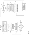
FIG. 6 is a flow diagram illustrating a method of controlling a self-regulating thin film heating arrangement included in an air data probe according to a non-limiting embodiment. - A detailed description of one or more embodiments of the disclosed apparatus and method are presented herein by way of exemplification and not limitation with reference to the Figures.
- Air data probes have recently began implementing thin film heaters instead of conventional coil-based resistive heating elements because they provide improved reliable using less-complex designs. However, as the temperature surrounding the air data probe increases above freezing temperature, the inherent characteristic of a CNT heater causes its resistance to decrease which can cause excessive energy consumption and overheating.
- There is provided herein an air data probe that implements a thin film heater including a positive temperature coefficient (PTC) heating element in series connection with a negative coefficient temperature (NTC) heating element. The PTC heating element includes a carbon black and polymer composite heater, while the NTC heating element includes a carbon nanotube (CNT) and silicon composite heater (also referred to as a CNT heater).
- CNT heaters exhibit NTC characteristics at low temperatures and can provide an improvement in energy consumption over conventional coil-based heating elements by about 20% to about 25%. PTC heaters exhibit PTC characteristics. For example, PTC heaters provide an electric resistance that increases with temperature and is also capable of self-regulating its temperature at a pre-defined higher temperature. Therefore, combining a PTC heating element in series with a CNT heater allows the CNT heater to efficiently heat the air data probe during freezing conditions, while the PTC heating element regulates the CNT heater as surrounding temperatures increase above freezing conditions.
- With reference now to
FIG. 1 , anair data probe 10 is illustrated according to a non-limiting embodiment. Although theair data probe 10 is constructed as apitot tube 10, a variety of different air data probe designs may be implemented without deviating from the scope of the invention. Theair data probe 10 is secured to anexternal surface 12 of an aircraft or other structure. Theair data probe 10 includes abase 14 located at theexternal surface 12, and astrut assembly 16 extending from thebase 14 to anupper strut portion 20. Atube assembly 18 is located at theupper strut portion 20. Thetube assembly 18 includes acylindrical body portion 22 and atip portion 24 extending along atube axis 26 from thebody portion 22 to atube inlet 28 which allows andairflow 30 to enter thetube assembly 18. - The
air data probe 10 is configured to include self-regulating thinfilm heating assemblies strut assembly 16 and thetube assembly 18, respectively. The self-regulating thin film heating assemblies 32 and 33 dissipate power when electrically energized so as to generate surface heating. The amount of power dissipated depends on the electric resistivitytemperature characteristics of the material employed in the self-regulating thinfilm heating arrangement - Turning to
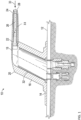
FIGS. 2A and 2B , astrut assembly 16 configured to support a self-regulating thinfilm heating arrangement 32 is illustrated according to a non-limiting embodiment. Thestrut assembly 16 can include a primary frustum and a secondary frustum are formed from a metallic material, such as a nickel material. In some embodiments, the secondary frustum has a secondary frustum surface arranged at a secondary frustum angle relative to the central axis. Thestrut assembly 16 can further include astrut sleeve 34 extending from one end disposed on thebase 14 to an opposing end disposed at anupper strut portion 20. The self-regulating thinfilm heating arrangement 32 can be installed or wrapped about the outer surface of thestrut sleeve 34, and astrut housing 38 can be installed over the self-regulating thinfilm heating arrangement 32 andstrut sleeve 34. Thestrut housing 38 is a hollow structure with a strut housinginner surface 40. - Turning to
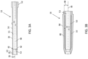
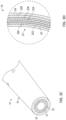
FIGS. 3A, 3B , and3C and 3D , atube assembly 18 configured to support a self-regulating thinfilm heating arrangement 33 is illustrated according to a non-limiting embodiment. Thetube assembly 18 is constructed with ahollow tube sleeve 50 extending from aproximate end 52 coupled to theupper strut portion 20 to adistal end 53 that terminates thetube inlet 28. Thetube sleeve 50 includes a sleeveouter surface 54 located opposite a sleeveinner surface 55, and has a sleeve frustum angle relative to atube axis 58. The sleeve frustum angle is configured such that the sleeveouter surface 54 has a reducing radial distance from thetube axis 58 with reducing distance from thetube inlet 28. Further, in some embodiments, the sleeveouter surface 54 has a furthertapered portion 60 at or near athroat 62 of thetube assembly 18. Thetube sleeve 50 includes acylindrical surface 63 at or near thetube inlet 28. - The self-regulating thin
film heating arrangement 33 can be installed or wrapped about the sleeveouter surface 54, and atube housing 64 can be installed over the self-regulating thinfilm heating arrangement 32 andtube sleeve 50. Thetube housing 64 is a hollow, tubular structure with aninner housing surface 66. The sleevecylindrical surface 63 allows for brazing of thetube sleeve 50 to thetube housing 64 during assembly without damaging the self-regulating thinfilm heating arrangement 33. - The self-regulating thin
film heating arrangement 32 and/or 33 includes nano-composites of carbon allotropes. According to the invention, the self-regulating thinfilm heating arrangement film heating arrangement 32 and/or 33 may include one or more insulation layers to prevent current leakage from and short circuit of the self-regulating thinfilm heating arrangement 32 and/or 33. - When implementing the self-regulating thin
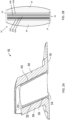
film heating arrangement 32 in thestrut assembly 16, the PTC heating element (e.g., a carbon black/polymer composite heater) 200, one or more insulation layers 202, 204, 206, and the NTC heating element 208 (i.e., a carbon nanotube/silicone heater) can be stacked between thestrut housing 38 and thestrut sleeve 34. Referring toFIG. 2B , for example, each of thePTC heating element 200, the insulation layers 202, 204, 206, and theNTC heating element 208 extend from a first end that is disposed adjacent to the base 14 to a second end that is disposed opposite the first end and adjacent to theupper strut portion 20. One non-limiting embodiment provides thePTC heating element 200 between afirst insulation layer 202 disposed against thestrut housing 38 and asecond insulation layer 204. TheNTC heating element 208 is interposed between thesecond insulation layer 204 and athird insulation layer 206 disposed against thesurface 36 of thestrut sleeve 34. In some embodiments, the combined thickness of the self-regulating thinfilm heating arrangement 32 and the insulation layers 202, 204, 206 is on the order of 0.03". Further, end regions of the assembly can be sealed to prevent the self-regulating thinfilm heating arrangement 32 from being subjected to external corrosive elements. In one or more non-limiting embodiments, the PTC and CNT can include terminals (not shown) to establish electrical connections between one another. Although not illustrated, it should be appreciated that another non-limiting embodiment disposes theNTC heating element 208 between afirst insulation layer 202 formed against thestrut housing 38 and asecond insulation layer 204, while thePTC heating element 200 is interposed between thesecond insulation layer 204 and athird insulation layer 206 disposed against theouter surface 36 of thestrut sleeve 34. - When implementing the self-regulating thin
film heating arrangement 33 in thetube assembly 18, the PTC heating element 200 (e.g., a carbon black/polymer composite heater), the insulation layers 202, 204, 206, and the NTC heating element 208 (e.g., a carbon nanotube/silicone heater) are cylindrically stacked between the inner sleeve and an inner surface of the cylindrical housing (seeFIG. 3C ). Referring toFIG. 3D , for example, one non-limiting embodiment provides thePTC heating element 200 between afirst insulation layer 202 disposed against thetube sleeve 50 and asecond insulation layer 204. TheNTC heating element 208 is interposed between thesecond insulation layer 204 and athird insulation layer 206 disposed against the inner surface of thetube housing 64. In some embodiments, the combined thickness of the self-regulating thinfilm heating arrangement 33 and the insulation layers 202, 204, 206 is on the order of 0.03". Further, end regions of the assembly can be sealed to prevent the self-regulating thinfilm heating arrangement 33 from being subjected to external corrosive elements. In one or more non-limiting embodiments, the PTC and CNT can include terminals to establish electrical connections between one another. Although not illustrated, it should be appreciated that another non-limiting embodiment disposes theNTC heating element 208 between afirst insulation layer 202 formed against thetube sleeve 50 and asecond insulation layer 204, while thePTC heating element 200 is interposed between thesecond insulation layer 204 and athird insulation layer 206 disposed against the inner surface of thetube housing 64. Theinsulation layer 206 can be formed of various known dielectric materials. - Turning to
FIG. 4 , acircuit 400 of a self-regulating thinfilm heating arrangement 33 included in atube assembly 18 connected in series with a self-regulating thinfilm heating arrangement 32 included in astrut assembly 16 is illustrated according to a non-limiting embodiment. The tube self-regulating thinfilm heating arrangement 33 includes atube input node 400 and atube output node 402. The strut self-regulating thin film heating arrangement includes astrut input node 404 and astrut output node 406. - In one or more non-limiting embodiments, the
tube input node 400 is in signal communication with avoltage source 408 and thetube output node 402 is in signal communication with thestrut input node 404. Thestrut output node 406 is in signal communication with aground potential 410, thereby providing aseries circuit 400 where the tube self-regulating thinfilm heating arrangement 33 is connected in series with the strut self-regulating thinfilm heating arrangement 32. It should be appreciated that in other embodiments, thestrut input node 404 is in signal communication with avoltage source 408 and thestrut output node 406 is in signal communication with thetube input node 400. Thetube output node 402 can be in signal communication with aground potential 410, thereby providing aseries circuit 400 where the strut self-regulating thinfilm heating arrangement 32 is connected in series with the tube self-regulating thinfilm heating arrangement 33. In either case, the effective total resistance of theseries circuit 400 is the sum of the total resistance of the tube self-regulating thin film heating arrangement 33 (Rtot, tube) and the total resistance of the strut self-regulating thin film heating arrangement 32 (Rtot, strut), i.e., Rtot, pitot = (Rtot, tube) + (Rtot, strut). - Referring to
FIG. 5 , acircuit 400 of a self-regulating thinfilm heating arrangement 33 included in atube assembly 18 and a self-regulating thinfilm heating arrangement 32 included in astrut assembly 16 is illustrated according to a non-limiting embodiment. The total effective resistance of the tube self-regulating thinfilm heating arrangement 33 and/or the strut self-regulating thinfilm heating arrangement 32 is shown as the sum of the resistance of the PTC heating element 200 (e.g. PTC heater 200) and the resistance of the NTC heating element 208 (e.g., a CNT heater 208) i.e., Rtotal = PTC(Rn) + CNT(Rn). - The resistance variations according to temperatures of the
PTC heater 200 and/or theCNT heater 208 can be tailor-made or designed per application to match targeted power dissipation profiles and maximum targeted temperatures or target temperature thresholds. The total effective resistance of thePTC heater 200 and the CNT heater 208 (i.e., PTC(Rn) + CNT(Rn)) is designed such that effective series circuit resistance (R1+R2) is made less than or equal to the existing resistance wire heater at lower temperatures. For each of the heater units (i.e., thePTC heater 200 and the CNT heater 208) installed in thetube assembly 18 and thestrut assembly 18, thePTC heater 200 has different electrical resistivity characteristics (compared to the CNT electrical characteristics), which can be customized to achieve a targeted maximum temperature or temperature threshold that will output a targeted maximum current output to theCNT heater 208. Referring to the tube self-regulating thinfilm heating arrangement 33, for example, the effective resistance of thePTC heater 200 connected in series with theCNT heater 208 is less than a conventional wire heater resistance at lower temperature and will increase to a higher targeted maximum temperature based on the design of thePTC heater 200. - At higher temperatures, the
PTC heater 200 increases its resistance exponentially until the targeted temperature threshold is reached. In turn, the current level of the current output to theCNT heater 208 is reduced, thereby reducing the power dissipation by theCNT heater 208. In this manner, thePTC heater 200 is capable of self-regulating the temperature of the thin film heating arrangement to avoid overheating and excessive power consumption. Connecting thePTC heater 200 in series with theCNT heater 208 also facilitates uniform heating, thereby avoiding concentrated hot spots on the surfaces of thetube assembly 18 and/or strutassembly 16. - With reference to
FIG. 6 , a method of controlling a self-regulating thin film heating arrangement included in an air data probe is illustrated according to a non-limiting embodiment. The method begins atoperation 600, and at operation 602 a PTC heating element (e.g., a PTC heater) is connected in series with an NTC heating element (e.g., a CNT heater) to establish a self-regulating thin film heating arrangement. Atoperation 604, current is delivered to the PTC heating element and the PTC heating element outputs current having a current level to the NTC heating element atoperation 606. Atoperation 608, the NTC heating element dissipates power based on the current output from the PTC heating element. The power is dissipated in the form of heat, which heats the air data probe. The temperature of the heat is based on the level of the current output from the PTC heating element. - At
operation 610, a determination is made as to whether the temperature of the PTC heating element changes. For example, changes in the temperatures surrounding the air data probe can change the temperature of the PTC heating element. When the temperature remains constant or substantially constant, the method returns tooperation 606 and continues outputting the current at the current level. When the temperature changes, however,operation 612 determines whether the PTC heating element has reached a targeted temperature threshold (e.g., a maximum pre-set temperature). - When the PTC heating element has not reached the temperature threshold, the resistance of the PTC heating element changes at
operation 614. For example, the resistance of the PTC heating element changes as the temperature of the PTC heating element decreases, while the resistance of the PTC heating element increases as the temperature of the PTC heating element increases. The varying resistance in response to the change in temperature is an inherent characteristic of a carbon black/polymer composite heater, which can be used to form the PTC heating element. Atoperation 616, the current level of the current output from the PTC heating element is changed based on the temperature change of the PTC heating element. For example, when the temperature of the PTC heating element increases atoperation 614, the resistance of the PTC heating element increases thereby decreasing the current output to the NTC heating element. Atoperation 618, the NTC heating element dissipates the power based on the changed current level (e.g., the decreased current) output from the PTC heating element. Accordingly, the temperature of the heat emitted by the NTC heating element changes (e.g., decreases), and the method returns tooperation 610 to determine if the temperature of the PTC heating element has changed. - When, however, the temperature of the PTC heating element has reached the temperature threshold at
operation 612, the resistance of the PTC heating element is maintained, or substantially maintained, and the current level of the current output to the NTC heating element is also maintained, or substantially maintained atoperation 620. Accordingly, the temperature of the heat emitted by the NTC heating element is maintained, or substantially maintained, and the method returns to operation to determine if the temperature of the PTC heating element has changed. - The air data probe configurations disclosed herein provide enhanced safety and service life by preventing heater failure and excessive power consumption. Further, the heating profile of the air data probe may be customized to meet requirements by, for example, modifying the electrical characteristics of the self-regulating thin film heating arrangement (e.g., the PTC heating element and/or the NTC heating element) without changing an external design of the air data probe.
- The term "about" is intended to include the degree of error associated with measurement of the particular quantity based upon the equipment available at the time of filing the application.
- The terminology used herein is for the purpose of describing particular embodiments only and is not intended to be limiting of the present disclosure. As used herein, the singular forms "a", "an" and "the" are intended to include the plural forms as well, unless the context clearly indicates otherwise. It will be further understood that the terms "comprises" and/or "comprising," when used in this specification, specify the presence of stated features, integers, steps, operations, elements, and/or components, but do not preclude the presence or addition of one or more other features, integers, steps, operations, element components, and/or groups thereof.
- While the present disclosure has been described with reference to an exemplary embodiment or embodiments, it will be understood by those skilled in the art that various changes may be made without departing from the scope of the appended claims. The present disclosure will include all embodiments falling within the scope of the claims.
Claims (15)
- An air data probe (10), comprising:a strut assembly (16) extending from a base (14); anda tube assembly (18) coupled to the strut assembly and extending therefrom,a self-regulating thin film heating arrangement (32) in operable communication with the strut assembly (16) and the tube assembly (18), the self-regulating thin film heating arrangement (32) comprising at least one circuit including a positive temperature coefficient (PTC) heating element connected in series with a negative temperature coefficient (NTC) heating element; and characterized in thatthe strut assembly (16) includes a strut self-regulating thin film heating arrangement (32) and the tube assembly (18) includes a tube self-regulating thin film heating arrangement (33) connected in series with the strut self-regulating thin film heating arrangement; andthe tube self-regulating thin film heating arrangement (33) and the strut self-regulating thin film heating arrangement (32) each include a carbon black and polymer composite heater forming the PTC heating element connected in series with a carbon nanotube and silicone heater forming the NTC heating element.
- The air data probe of claim 1, wherein the tube self-regulating thin film heating arrangement (33) includes a tube input node (400) and a tube output node (402), and the strut self-regulating thin film heating arrangement (32) includes a strut input node (404) and a strut output node (406).
- The air data probe of claim 2, wherein the tube input node (400) is in signal communication with a voltage source and the tube output node (402) is in signal communication with the strut input node (404), and wherein the strut output node (406) is in signal communication with a ground potential.
- The air date probe of claim 3, wherein at least one insulation layer (202, 204, 206) is interposed between the carbon black and polymer composite heater and the carbon nanotube and silicone heater.
- The air date probe of claim 4, wherein the tube assembly (18) comprises a cylindrical housing extending about a tube axis and an inner sleeve disposed within the cylindrical housing, and preferably wherein the carbon black and polymer composite heater, the at least one insulation layer, and the carbon nanotube and silicone heater are cylindrically stacked between the inner sleeve and an inner surface of the cylindrical housing.
- The air data probe of claim 4, wherein the strut assembly (16) comprises a strut housing (38) and a strut sleeve (34) disposed in the strut housing, the strut sleeve extending from the base to an upper strut portion located opposite the base.
- The air data probe of claim 6, wherein the carbon black and polymer composite heater, the at least one insulation layer, and the carbon nanotune and silicone heater are stacked between the strut housing and the strut sleeve, and preferably wherein the carbon black and polymer composite heater, the at least one insulation layer, and the carbon nanotube and silicone heater extend from a first end disposed adjacent to the base and a second end disposed opposite the first end and adjacent to the upper strut portion.
- A method of controlling heating of the self-regulating thin film heating arrangement included in the air data probe of any preceding claim, the method comprising:delivering an electrical current to the at least one self-regulating thin film heating arrangement including the positive temperature coefficient, PTC, heating element connected in series with the negative temperature coefficient, NTC, heating element;dissipating power via the NTC heating element in response to flowing the current therethrough to generate heat; andvarying the heat emitted from the NTC heating element in response to varying a temperature surrounding the PTC heating element.
- The method of claim 8, further comprising varying a resistance of the PTC heating element in response to varying the temperature surrounding the PTC heating element.
- The method of claim 9, wherein varying the resistance includes decreasing the resistance as the surrounding temperature decreases and increasing the resistance as the surrounding temperature increases.
- The method of claim 10, wherein the PTC heating element outputs the current to the NTC heating element at a first current level while operating at a first surrounding temperature, and outputs the current to the NTC heating element at a second current level while operating a second surrounding temperature different than the first surrounding temperature.
- The method of claim 11, wherein the second current level is less than the first current level, and wherein the second temperature is greater than the first temperature.
- The method of claim 12, wherein the NTC heating element emits heat having a first temperature in response to receiving the current having the first current, and emits the heat having a second temperature in response to receiving the current having the second current level.
- The method of claim 11, wherein the second temperature is less than the first temperature.
- The method of claim 14, wherein the tube self-regulating thin film heating arrangement is disposed in a tube assembly and wherein a strut self-regulating thin film heating arrangement is disposed in a strut assembly of the air data probe, the strut assembly is thermal communication with the tube assembly.
Applications Claiming Priority (1)
| Application Number | Priority Date | Filing Date | Title |
|---|---|---|---|
| IN201911043806 | 2019-10-29 |
Publications (2)
| Publication Number | Publication Date |
|---|---|
| EP3816634A1 EP3816634A1 (en) | 2021-05-05 |
| EP3816634B1 true EP3816634B1 (en) | 2024-04-17 |
Family
ID=72801372
Family Applications (1)
| Application Number | Title | Priority Date | Filing Date |
|---|---|---|---|
| EP20200540.1A Active EP3816634B1 (en) | 2019-10-29 | 2020-10-07 | Air data probe including self-regulating thin film heater |
Country Status (2)
| Country | Link |
|---|---|
| US (1) | US11425797B2 (en) |
| EP (1) | EP3816634B1 (en) |
Families Citing this family (8)
| Publication number | Priority date | Publication date | Assignee | Title |
|---|---|---|---|---|
| US11209330B2 (en) * | 2015-03-23 | 2021-12-28 | Rosemount Aerospace Inc. | Corrosion resistant sleeve for an air data probe |
| US11414195B2 (en) | 2018-03-23 | 2022-08-16 | Rosemount Aerospace Inc. | Surface modified heater assembly |
| US11428707B2 (en) | 2019-06-14 | 2022-08-30 | Rosemount Aerospace Inc. | Air data probe with weld sealed insert |
| US11585826B2 (en) * | 2019-07-19 | 2023-02-21 | Rosemount Aerospace Inc. | Thin film heater on a sleeve outer surface in a strut portion and/or a probe head of an air data probe |
| US11745879B2 (en) | 2020-03-20 | 2023-09-05 | Rosemount Aerospace Inc. | Thin film heater configuration for air data probe |
| US11731780B2 (en) | 2021-09-09 | 2023-08-22 | Hamilton Sundstrand Corporation | Aircraft system including a cryogenic fluid operated auxiliary power unit (APU) |
| US11624637B1 (en) | 2021-10-01 | 2023-04-11 | Rosemount Aerospace Inc | Air data probe with integrated heater bore and features |
| US11662235B2 (en) | 2021-10-01 | 2023-05-30 | Rosemount Aerospace Inc. | Air data probe with enhanced conduction integrated heater bore and features |
Family Cites Families (32)
| Publication number | Priority date | Publication date | Assignee | Title |
|---|---|---|---|---|
| US4458137A (en) | 1981-04-09 | 1984-07-03 | Rosemount Inc. | Electric heater arrangement for fluid flow stream sensors |
| GB8604519D0 (en) | 1986-02-24 | 1986-04-03 | Raychem Sa Nv | Electrical devices |
| FR2695203B1 (en) | 1992-08-28 | 1994-11-04 | Intertechnique Sa | Thermistor liquid detector. |
| US5543183A (en) * | 1995-02-17 | 1996-08-06 | General Atomics | Chromium surface treatment of nickel-based substrates |
| EP1186206B1 (en) | 1999-05-14 | 2008-12-10 | Asuk Technologies, LLC | Electrical heating devices and resettable fuses |
| US6591696B2 (en) * | 2001-07-12 | 2003-07-15 | Rosemount Aerospace, Inc. | Integral electric pressure probe for aircraft |
| GB0427650D0 (en) | 2004-12-17 | 2005-01-19 | Heat Trace Ltd | Electrical device |
| GB0428297D0 (en) | 2004-12-24 | 2005-01-26 | Heat Trace Ltd | Control of heating cable |
| KR100749886B1 (en) | 2006-02-03 | 2007-08-21 | (주) 나노텍 | Heating element using Carbon Nano tube |
| GB0609729D0 (en) | 2006-05-17 | 2006-06-28 | Heat Trace Ltd | Material and heating cable |
| SE530660C2 (en) | 2006-10-17 | 2008-08-05 | Conflux Ab | Positive temperature coefficient superimposed impedance polymeric compound used in heating elements comprises electrically insulating matrix with amorphous polymer and two electrically conductive particles having different surface energies |
| GB0700079D0 (en) | 2007-01-04 | 2007-02-07 | Boardman Jeffrey | A method of producing electrical resistance elements whihc have self-regulating power output characteristics by virtue of their configuration and the material |
| US20100116806A1 (en) | 2007-05-08 | 2010-05-13 | Honeywell International Inc. | Automated heating system for ports susceptible to icing |
| US8164035B2 (en) | 2008-04-17 | 2012-04-24 | Long-Huang Chang | Heating device having dual-core heating cable |
| GB0817082D0 (en) | 2008-09-18 | 2008-10-29 | Heat Trace Ltd | Heating cable |
| US8496854B2 (en) | 2009-10-30 | 2013-07-30 | Sabic Innovative Plastics Ip B.V. | Positive temperature coefficient materials with reduced negative temperature coefficient effect |
| US8481898B2 (en) | 2010-06-04 | 2013-07-09 | Robert Parker | Self regulating electric heaters |
| DE102011119844A1 (en) | 2011-05-26 | 2012-12-13 | Eads Deutschland Gmbh | Composite structure with ice protection device and manufacturing process |
| WO2014188190A1 (en) | 2013-05-21 | 2014-11-27 | Heat Trace Limited | Electrical heater |
| US10373745B2 (en) | 2014-06-12 | 2019-08-06 | LMS Consulting Group | Electrically conductive PTC ink with double switching temperatures and applications thereof in flexible double-switching heaters |
| KR101602880B1 (en) | 2014-06-18 | 2016-03-11 | (주)유니플라텍 | Positive temperature coefficient using conductive liquid emulsion polymer composition, manufacturing method of thereoff, Face heater with it |
| US11542018B2 (en) | 2015-01-06 | 2023-01-03 | Battelle Memorial Institute | Uniform heat distribution in resistive heaters for anti-icing and de-icing |
| DE102015107316B4 (en) | 2015-05-11 | 2023-10-12 | Borgwarner Ludwigsburg Gmbh | Electric heater |
| US9668301B2 (en) | 2015-07-03 | 2017-05-30 | Ndt Engineering & Aerospace Co., Ltd. | Wet-use plane heater using PTC constant heater-ink polymer |
| CA2964260A1 (en) | 2016-06-28 | 2017-12-28 | Rosemount Aerospace Inc. | Air data sensing probe with icing condition detector |
| US10368394B2 (en) | 2016-09-01 | 2019-07-30 | Hamilton Sundstrand Corporation | PTC heater with autonomous control |
| US11297692B2 (en) | 2016-11-01 | 2022-04-05 | Goodrich Corporation | Multilayered panels |
| US10197588B2 (en) | 2016-11-09 | 2019-02-05 | Honeywell International Inc. | Thin film heating systems for air data probes |
| US11382181B2 (en) | 2016-12-02 | 2022-07-05 | Goodrich Corporation | Method to create carbon nanotube heaters with varying resistance |
| US11235881B2 (en) * | 2018-09-13 | 2022-02-01 | Goodrich Corporation | Hybrid heater for aircraft wing ice protection |
| US11167856B2 (en) * | 2018-12-13 | 2021-11-09 | Goodrich Corporation Of Charlotte, Nc | Multilayer structure with carbon nanotube heaters |
| US11745879B2 (en) * | 2020-03-20 | 2023-09-05 | Rosemount Aerospace Inc. | Thin film heater configuration for air data probe |
-
2020
- 2020-01-08 US US16/736,953 patent/US11425797B2/en active Active
- 2020-10-07 EP EP20200540.1A patent/EP3816634B1/en active Active
Also Published As
| Publication number | Publication date |
|---|---|
| US11425797B2 (en) | 2022-08-23 |
| EP3816634A1 (en) | 2021-05-05 |
| US20210127458A1 (en) | 2021-04-29 |
Similar Documents
| Publication | Publication Date | Title |
|---|---|---|
| EP3816634B1 (en) | Air data probe including self-regulating thin film heater | |
| EP3173797B1 (en) | Air data probe with double helical coil heater cable | |
| EP3766783B1 (en) | Thin film heating of air data probes | |
| EP0076306B1 (en) | Passive temperature control arrangement for fluid flow stream sensor heater | |
| EP3321692A1 (en) | Air data probe with thin film heating system and method of manufacturing the air data probe | |
| CN107037234B (en) | Pitot tube made of hybrid material | |
| CN111328159A (en) | Multilayer structure with carbon nanotube heater | |
| US20110309068A1 (en) | Heating element for a hot air device | |
| JP7062624B2 (en) | Heater system and its operation method and its heater | |
| EP1997731A2 (en) | Automated heating system for ports susceptible to icing | |
| US6211494B1 (en) | Drainmast with integral electronic temperature control | |
| US9097734B2 (en) | Ceramic heating device | |
| EP3624554A1 (en) | Hybrid heater for aircraft wing ice protection | |
| CN209879344U (en) | Air data probe and pitot tube with induction heating | |
| US11745879B2 (en) | Thin film heater configuration for air data probe | |
| JP2013026222A (en) | Heating system, heater, and methods of heating component | |
| US20090010625A1 (en) | Flow Through Heater | |
| US20210153306A1 (en) | Heating module | |
| JPS63281375A (en) | Electric heating cable and assembly of the same | |
| JPH07217886A (en) | Self-controlled type ceramic glow plug | |
| EP1477780A1 (en) | Mass flowmeter for measuring by the constant temperature method | |
| JPH07103481A (en) | Glow plug made of ceramics | |
| JP2022184800A (en) | Exhaust gas heater | |
| KR20230077182A (en) | Device for generating aerosol | |
| JPH07103479A (en) | Glow plug made of ceramics |
Legal Events
| Date | Code | Title | Description |
|---|---|---|---|
| PUAI | Public reference made under article 153(3) epc to a published international application that has entered the european phase |
Free format text: ORIGINAL CODE: 0009012 |
|
| STAA | Information on the status of an ep patent application or granted ep patent |
Free format text: STATUS: THE APPLICATION HAS BEEN PUBLISHED |
|
| AK | Designated contracting states |
Kind code of ref document: A1 Designated state(s): AL AT BE BG CH CY CZ DE DK EE ES FI FR GB GR HR HU IE IS IT LI LT LU LV MC MK MT NL NO PL PT RO RS SE SI SK SM TR |
|
| STAA | Information on the status of an ep patent application or granted ep patent |
Free format text: STATUS: REQUEST FOR EXAMINATION WAS MADE |
|
| 17P | Request for examination filed |
Effective date: 20211102 |
|
| RBV | Designated contracting states (corrected) |
Designated state(s): AL AT BE BG CH CY CZ DE DK EE ES FI FR GB GR HR HU IE IS IT LI LT LU LV MC MK MT NL NO PL PT RO RS SE SI SK SM TR |
|
| STAA | Information on the status of an ep patent application or granted ep patent |
Free format text: STATUS: EXAMINATION IS IN PROGRESS |
|
| 17Q | First examination report despatched |
Effective date: 20220812 |
|
| GRAP | Despatch of communication of intention to grant a patent |
Free format text: ORIGINAL CODE: EPIDOSNIGR1 |
|
| STAA | Information on the status of an ep patent application or granted ep patent |
Free format text: STATUS: GRANT OF PATENT IS INTENDED |
|
| RIC1 | Information provided on ipc code assigned before grant |
Ipc: G01F 1/46 20060101ALN20231121BHEP Ipc: B64D 15/14 20060101ALN20231121BHEP Ipc: H05B 3/58 20060101ALI20231121BHEP Ipc: G01P 5/165 20060101AFI20231121BHEP |
|
| INTG | Intention to grant announced |
Effective date: 20231204 |
|
| GRAS | Grant fee paid |
Free format text: ORIGINAL CODE: EPIDOSNIGR3 |
|
| GRAA | (expected) grant |
Free format text: ORIGINAL CODE: 0009210 |
|
| STAA | Information on the status of an ep patent application or granted ep patent |
Free format text: STATUS: THE PATENT HAS BEEN GRANTED |
|
| AK | Designated contracting states |
Kind code of ref document: B1 Designated state(s): AL AT BE BG CH CY CZ DE DK EE ES FI FR GB GR HR HU IE IS IT LI LT LU LV MC MK MT NL NO PL PT RO RS SE SI SK SM TR |
|
| REG | Reference to a national code |
Ref country code: GB Ref legal event code: FG4D |
|
| REG | Reference to a national code |
Ref country code: CH Ref legal event code: EP |
|
| REG | Reference to a national code |
Ref country code: DE Ref legal event code: R096 Ref document number: 602020029065 Country of ref document: DE |
|
| REG | Reference to a national code |
Ref country code: IE Ref legal event code: FG4D |
|
| REG | Reference to a national code |
Ref country code: LT Ref legal event code: MG9D |
|
| REG | Reference to a national code |
Ref country code: NL Ref legal event code: MP Effective date: 20240417 |
|
| REG | Reference to a national code |
Ref country code: AT Ref legal event code: MK05 Ref document number: 1677726 Country of ref document: AT Kind code of ref document: T Effective date: 20240417 |
|
| PG25 | Lapsed in a contracting state [announced via postgrant information from national office to epo] |
Ref country code: NL Free format text: LAPSE BECAUSE OF FAILURE TO SUBMIT A TRANSLATION OF THE DESCRIPTION OR TO PAY THE FEE WITHIN THE PRESCRIBED TIME-LIMIT Effective date: 20240417 |
|
| PG25 | Lapsed in a contracting state [announced via postgrant information from national office to epo] |
Ref country code: NL Free format text: LAPSE BECAUSE OF FAILURE TO SUBMIT A TRANSLATION OF THE DESCRIPTION OR TO PAY THE FEE WITHIN THE PRESCRIBED TIME-LIMIT Effective date: 20240417 |
|
| PG25 | Lapsed in a contracting state [announced via postgrant information from national office to epo] |
Ref country code: IS Free format text: LAPSE BECAUSE OF FAILURE TO SUBMIT A TRANSLATION OF THE DESCRIPTION OR TO PAY THE FEE WITHIN THE PRESCRIBED TIME-LIMIT Effective date: 20240817 |
|
| PG25 | Lapsed in a contracting state [announced via postgrant information from national office to epo] |
Ref country code: BG Free format text: LAPSE BECAUSE OF FAILURE TO SUBMIT A TRANSLATION OF THE DESCRIPTION OR TO PAY THE FEE WITHIN THE PRESCRIBED TIME-LIMIT Effective date: 20240417 |
|
| PG25 | Lapsed in a contracting state [announced via postgrant information from national office to epo] |
Ref country code: FI Free format text: LAPSE BECAUSE OF FAILURE TO SUBMIT A TRANSLATION OF THE DESCRIPTION OR TO PAY THE FEE WITHIN THE PRESCRIBED TIME-LIMIT Effective date: 20240417 Ref country code: HR Free format text: LAPSE BECAUSE OF FAILURE TO SUBMIT A TRANSLATION OF THE DESCRIPTION OR TO PAY THE FEE WITHIN THE PRESCRIBED TIME-LIMIT Effective date: 20240417 |
|
| PG25 | Lapsed in a contracting state [announced via postgrant information from national office to epo] |
Ref country code: GR Free format text: LAPSE BECAUSE OF FAILURE TO SUBMIT A TRANSLATION OF THE DESCRIPTION OR TO PAY THE FEE WITHIN THE PRESCRIBED TIME-LIMIT Effective date: 20240718 |
|
| PG25 | Lapsed in a contracting state [announced via postgrant information from national office to epo] |
Ref country code: PT Free format text: LAPSE BECAUSE OF FAILURE TO SUBMIT A TRANSLATION OF THE DESCRIPTION OR TO PAY THE FEE WITHIN THE PRESCRIBED TIME-LIMIT Effective date: 20240819 |
|
| PGFP | Annual fee paid to national office [announced via postgrant information from national office to epo] |
Ref country code: GB Payment date: 20240919 Year of fee payment: 5 |
|
| PGFP | Annual fee paid to national office [announced via postgrant information from national office to epo] |
Ref country code: FR Payment date: 20240919 Year of fee payment: 5 |