EP3883337A1 - Dünnschichtheizungskonfiguration für eine luftdatensonde - Google Patents
Dünnschichtheizungskonfiguration für eine luftdatensonde Download PDFInfo
- Publication number
- EP3883337A1 EP3883337A1 EP21163469.6A EP21163469A EP3883337A1 EP 3883337 A1 EP3883337 A1 EP 3883337A1 EP 21163469 A EP21163469 A EP 21163469A EP 3883337 A1 EP3883337 A1 EP 3883337A1
- Authority
- EP
- European Patent Office
- Prior art keywords
- heater
- ptc
- layer
- cnt
- hybrid
- Prior art date
- Legal status (The legal status is an assumption and is not a legal conclusion. Google has not performed a legal analysis and makes no representation as to the accuracy of the status listed.)
- Granted
Links
Images

Classifications
-
- H—ELECTRICITY
- H05—ELECTRIC TECHNIQUES NOT OTHERWISE PROVIDED FOR
- H05B—ELECTRIC HEATING; ELECTRIC LIGHT SOURCES NOT OTHERWISE PROVIDED FOR; CIRCUIT ARRANGEMENTS FOR ELECTRIC LIGHT SOURCES, IN GENERAL
- H05B3/00—Ohmic-resistance heating
- H05B3/20—Heating elements having extended surface area substantially in a two-dimensional [2D] plane, e.g. plate-heater
- H05B3/22—Heating elements having extended surface area substantially in a two-dimensional [2D] plane, e.g. plate-heater non-flexible
- H05B3/26—Heating elements having extended surface area substantially in a two-dimensional [2D] plane, e.g. plate-heater non-flexible heating conductor mounted on insulating base
-
- B—PERFORMING OPERATIONS; TRANSPORTING
- B64—AIRCRAFT; AVIATION; COSMONAUTICS
- B64D—EQUIPMENT FOR FITTING IN OR TO AIRCRAFT; FLIGHT SUITS; PARACHUTES; ARRANGEMENT OR MOUNTING OF POWER PLANTS OR PROPULSION TRANSMISSIONS IN AIRCRAFT
- B64D15/00—De-icing or preventing icing on exterior surfaces of aircraft
- B64D15/12—De-icing or preventing icing on exterior surfaces of aircraft by electric heating
-
- G—PHYSICS
- G01—MEASURING; TESTING
- G01P—MEASURING LINEAR OR ANGULAR SPEED, ACCELERATION, DECELERATION, OR SHOCK; INDICATING PRESENCE, ABSENCE, OR DIRECTION, OF MOVEMENT
- G01P5/00—Measuring speed of fluids, e.g. of air stream; Measuring speed of bodies relative to fluids, e.g. of ship, of aircraft
- G01P5/14—Measuring speed of fluids, e.g. of air stream; Measuring speed of bodies relative to fluids, e.g. of ship, of aircraft by measuring differences of pressure in the fluid
- G01P5/16—Measuring speed of fluids, e.g. of air stream; Measuring speed of bodies relative to fluids, e.g. of ship, of aircraft by measuring differences of pressure in the fluid using Pitot tubes, e.g. Machmeter
- G01P5/165—Arrangements or constructions of Pitot tubes
-
- H—ELECTRICITY
- H05—ELECTRIC TECHNIQUES NOT OTHERWISE PROVIDED FOR
- H05B—ELECTRIC HEATING; ELECTRIC LIGHT SOURCES NOT OTHERWISE PROVIDED FOR; CIRCUIT ARRANGEMENTS FOR ELECTRIC LIGHT SOURCES, IN GENERAL
- H05B1/00—Details of electric heating devices
- H05B1/02—Automatic switching arrangements specially adapted to apparatus ; Control of heating devices
- H05B1/0227—Applications
- H05B1/023—Industrial applications
- H05B1/0236—Industrial applications for vehicles
-
- H—ELECTRICITY
- H05—ELECTRIC TECHNIQUES NOT OTHERWISE PROVIDED FOR
- H05B—ELECTRIC HEATING; ELECTRIC LIGHT SOURCES NOT OTHERWISE PROVIDED FOR; CIRCUIT ARRANGEMENTS FOR ELECTRIC LIGHT SOURCES, IN GENERAL
- H05B3/00—Ohmic-resistance heating
- H05B3/10—Heating elements characterised by the composition or nature of the materials or by the arrangement of the conductor
- H05B3/12—Heating elements characterised by the composition or nature of the materials or by the arrangement of the conductor characterised by the composition or nature of the conductive material
- H05B3/14—Heating elements characterised by the composition or nature of the materials or by the arrangement of the conductor characterised by the composition or nature of the conductive material the material being non-metallic
- H05B3/145—Carbon only, e.g. carbon black, graphite
-
- H—ELECTRICITY
- H05—ELECTRIC TECHNIQUES NOT OTHERWISE PROVIDED FOR
- H05B—ELECTRIC HEATING; ELECTRIC LIGHT SOURCES NOT OTHERWISE PROVIDED FOR; CIRCUIT ARRANGEMENTS FOR ELECTRIC LIGHT SOURCES, IN GENERAL
- H05B2203/00—Aspects relating to Ohmic resistive heating covered by group H05B3/00
- H05B2203/013—Heaters using resistive films or coatings
-
- H—ELECTRICITY
- H05—ELECTRIC TECHNIQUES NOT OTHERWISE PROVIDED FOR
- H05B—ELECTRIC HEATING; ELECTRIC LIGHT SOURCES NOT OTHERWISE PROVIDED FOR; CIRCUIT ARRANGEMENTS FOR ELECTRIC LIGHT SOURCES, IN GENERAL
- H05B2203/00—Aspects relating to Ohmic resistive heating covered by group H05B3/00
- H05B2203/017—Manufacturing methods or apparatus for heaters
-
- H—ELECTRICITY
- H05—ELECTRIC TECHNIQUES NOT OTHERWISE PROVIDED FOR
- H05B—ELECTRIC HEATING; ELECTRIC LIGHT SOURCES NOT OTHERWISE PROVIDED FOR; CIRCUIT ARRANGEMENTS FOR ELECTRIC LIGHT SOURCES, IN GENERAL
- H05B2203/00—Aspects relating to Ohmic resistive heating covered by group H05B3/00
- H05B2203/02—Heaters using heating elements having a positive temperature coefficient
-
- H—ELECTRICITY
- H05—ELECTRIC TECHNIQUES NOT OTHERWISE PROVIDED FOR
- H05B—ELECTRIC HEATING; ELECTRIC LIGHT SOURCES NOT OTHERWISE PROVIDED FOR; CIRCUIT ARRANGEMENTS FOR ELECTRIC LIGHT SOURCES, IN GENERAL
- H05B2214/00—Aspects relating to resistive heating, induction heating and heating using microwaves, covered by groups H05B3/00, H05B6/00
- H05B2214/02—Heaters specially designed for de-icing or protection against icing
-
- H—ELECTRICITY
- H05—ELECTRIC TECHNIQUES NOT OTHERWISE PROVIDED FOR
- H05B—ELECTRIC HEATING; ELECTRIC LIGHT SOURCES NOT OTHERWISE PROVIDED FOR; CIRCUIT ARRANGEMENTS FOR ELECTRIC LIGHT SOURCES, IN GENERAL
- H05B2214/00—Aspects relating to resistive heating, induction heating and heating using microwaves, covered by groups H05B3/00, H05B6/00
- H05B2214/03—Heating of hydrocarbons
-
- H—ELECTRICITY
- H05—ELECTRIC TECHNIQUES NOT OTHERWISE PROVIDED FOR
- H05B—ELECTRIC HEATING; ELECTRIC LIGHT SOURCES NOT OTHERWISE PROVIDED FOR; CIRCUIT ARRANGEMENTS FOR ELECTRIC LIGHT SOURCES, IN GENERAL
- H05B2214/00—Aspects relating to resistive heating, induction heating and heating using microwaves, covered by groups H05B3/00, H05B6/00
- H05B2214/04—Heating means manufactured by using nanotechnology
Definitions
- the following description relates to air data sensors, and more specifically, to heater systems for aircraft air data sensors.
- Ice accretion on aircraft air data sensors can render the air data sensors inoperable for their intended purpose.
- Heaters are implemented to prevent ice accretion or melt ice that has already accreted on air data sensors.
- nichrome-based metal alloy resistance heaters are used to heat air data sensors.
- nichrome-based metal alloy resistance heaters result in high power consumption without high heating capacity.
- a hybrid heater system for an aircraft air data sensor includes a voltage source and a first hybrid heater set.
- the first hybrid heater set includes a carbon nanotube (CNT) heater, a first positive temperature coefficient (PTC) heater disposed in parallel with the CNT heater to form a parallel formation, and a second PTC heater disposed in series between the voltage source and the parallel formation.
- CNT carbon nanotube
- PTC positive temperature coefficient
- a hybrid heater system for ice protection of an air data probe on an aircraft includes a voltage source, a carbon nanotube (CNT) heater, which includes CNT heater elements, a first positive temperature coefficient (PTC) heater disposed in parallel with the CNT heater to form a parallel formation, and a second PTC heater.
- the first PTC heater includes first PTC heater elements interleaved with the CNT heater elements in a first air data probe layer.
- the second PTC heater is disposed in a second air data probe layer and in series between the voltage source and the parallel formation.
- a method of making a heater for an air data probe includes positioning on the air data probe a first heater layer.
- the first heater layer includes a carbon nanotube (CNT) heater element and a first positive temperature coefficient (PTC) heater element interleaved with one another.
- the method of heating an air data probe further includes positioning on the air data probe a second heater layer.
- the second heater layer includes a second PTC heater element.
- the method of heating an air data probe further includes wiring the first heater layer and the second heater layer so that the CNT heater element and the first PTC heater element are in parallel with one another defining a parallel formation.
- the method of heating an air data probe further includes wiring the second heater layer so that the second PTC heater element is in series with the first parallel formation and a voltage source.
- the present disclosure relates to air data probes with hybrid heater systems using carbon nanotube (CNT) heaters and positive temperature coefficient (PTC) heaters.
- CNT heaters are made with carbon nanotube and a silicone composite.
- CNT heaters have a negative temperature coefficient (NTC) at low temperatures. Because CNT heaters have an NTC at low temperatures, the electrical resistance of CNT heaters is higher at low temperatures and drops drastically and stabilizes at a lower resistance level at higher temperatures.
- the NTC of CNT heaters makes CNT heaters great for quickly heating a device or mechanism. However, because CNT heaters have an NTC, there is no regulating mechanism at higher temperatures unless they are installed with temperature sensor feedback systems.
- PTC heaters increase in electrical resistance as temperature increases.
- the hybrid heater system is a self-regulating heater system using CNT and PTC heaters.
- the hybrid heater system for air data probes will be described below with reference to FIGS 1A-4B .
- FIGS 1A-1C will be discussed concurrently.
- FIG. 1A is a perspective view of air data sensor 10.
- FIG. 1B is a side view of air data sensor 10.
- FIG. 1C is a zoomed-in cross-sectional view taken along line A-A in FIG. 1B of air data sensor 10.
- Air data sensor 10 includes strut assembly 12 and housing assembly 14. Housing assembly 14 includes probe surface 16, hybrid thin-film heater system 18 ("heater system 18"), and probe sleeve 20.
- air data sensor 10 is a pitot-tube air data sensor.
- air data sensor 10 can be a pitot-static probe, multi-function probe with flow angle measurement, and/or any other air data sensor used on an aircraft.
- Strut assembly 12 attaches to an airplane (not shown) and extends radially outward from the airplane.
- Housing assembly 14 is tubular in shape and extends from strut assembly 12. Housing assembly 14 is generally parallel to the surface of the airplane.
- Sleeve 20 is within housing assembly 14 and guides airflow into air data sensor 10.
- heater system 18 can be installed within strut assembly 12 and housing assembly 14. As shown in FIG. 1C , heater system 18 is installed within housing assembly 14 between probe surface 16 and probe sleeve 20. Probe surface 16 is the exterior shell of air data sensor 10 and helps protect air data sensor 10 and heater system 18. Air flows into air data sensor 10 through probe sleeve 20. Probe sleeve 20 helps protect air data sensor 10 and heater system 18. Heater system 18 can effectively heat probe surface 16 and probe sleeve 20 to prevent ice accretion thereon. In the present embodiment, heater system 18 is installed within air data sensor 10. In another embodiment, heater system 18 can be installed on the exterior of air data sensor 10.
- FIG. 2A is a schematic illustration showing one configuration of heater system 18.
- first heater layer 22 and second heater layer 24 In between heater layer 22 and heater layer 24, is film adhesive and insulation 26. Film adhesive and insulation 26 is also used in between probe surface 16 and first heater layer 22 and between probe sleeve 20 and second heater layer 24. Film adhesive and insulation 26 help hold each heater layer (layers 22 and 24) in place within air data sensor 10. Film adhesive and insulation 26 further help insulate air data sensor 10.
- First heater layer 22 includes CNT heater 28 and first PTC heater 30.
- Second heater layer 24 includes second PTC heater 32. Because CNT heater 28 is made from carbon nanotube and silicone composite, CNT heater 28 is more rigid and durable than PTC heater 30 and PTC heater 32. Therefore, CNT heater 28 is in first heater layer 22 to protect first PTC heater 30 and second PTC heater 32.
- FIG. 2B is a schematic illustration showing first heater layer 22.
- First heater layer 22 includes positive terminal 34, negative terminal 36, PTC heater elements 38, and CNT heater elements 40.
- PTC heater elements 38 and CNT heater elements 40 extend from positive terminal 34 to negative terminal 36 and are interleaved with one another. As a result, PTC heater elements 38 and CNT heater elements 40 are connected physically and electrically in parallel to one another.
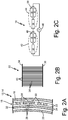
- FIG. 2C is a schematic diagram showing the configuration of heater system 18.
- Heater system 18 includes first heater set 42, second heater set 44, and voltage source 46.
- First heater set 42 includes CNT heater 28, first PTC heater 30, and second PTC heater 32.
- First CNT heater 28 and first PTC heater 30 are wired in parallel, forming first parallel formation 48.
- Second PTC heater 32 is wired in series between voltage source 46 and first parallel formation 48.
- First heater set 44 is installed within strut assembly 12 of air data sensor 10.
- the resistance of parallel formation 48 in first heater set 42 is less than each of the individual resistance of CNT heater 28 and first PTC heater 30. Therefore, parallel formation 48 ensures faster heating than CNT heater 28 would provide by itself.
- the resistance of second PTC heater 32 is selected so that the total resistance of second PTC heater 32 and parallel formation 48 is less than the resistance of CNT heater 28 at a set lower temperature (e.g., less than 20 °C).
- the resistance of second PTC heater 32 and parallel formation 48 is less than the resistance of CNT heater 28 at lower temperatures so that PTC heaters (30 and 34) do not impede CNT heater 28 at low temperatures.
- the resistance of second PTC heater 32 is further configured so that the resistance of second PTC heater 32 will increase to a maximum resistance at a set higher temperature, therefore the electrical resistivity of first PTC heater 30 and second PTC heater 32 do not need to be equal.
- the initial lower resistance of first heater set 42 when first heater set 42 is at a low temperature results in first heater set 42 rapidly heating strut assembly 12.
- the resistance of second PTC heater 32 increases to a maximum.
- second PTC heater 32 restricts the power input to first parallel formation 48. As a result of the power input being restricted to first parallel formation 48, first heater set 42 will not overheat and first heater set 42 will reduce the power consumption of heater system 18.
- First PTC heater 30 and second PTC 32 provide self-regulation of first heater set 42 and help mitigate either hot or cold spots on strut assembly 12.
- Second heater set 44 includes second CNT heater 50, third PTC heater 52, and fourth PTC heater 54.
- Third PTC heater 52 and second CNT heater 50 are wired in parallel, forming second parallel formation 56.
- Fourth PTC heater 54 is wired in series with voltage source 46 and second parallel formation 56.
- Second heater set 44 is within housing assembly 14 of air data sensor 10.
- the values of electrical resistance for second heater set 44 can be similar to the values discussed in relation to first heater set 42 above. In other embodiments, the values for the electrical resistance of second heater set 44 can be different than the values discussed in relation to first heater set. However, with different resistance values, the relationship of those values will be essentially the same as the relationship of the values in Table 1. For example, the resistance of parallel formation 56 in second heater set 44 is less than each of the individual resistance of second CNT heater 50 and third PTC heater 52. Therefore, second parallel formation 56 ensures faster heating than second CNT heater 50 would provide by itself.
- the resistance of fourth PTC heater 54 is selected so that the total resistance of fourth PTC heater 54 and second parallel formation 56 is less than the resistance of second CNT heater 50 at a lower temperature (e.g., less than 20 °C).
- the resistance of fourth PTC heater 54 and second parallel formation 56 is less than the resistance of second CNT heater 50 at lower temperatures so that PTC heaters (52 and 54) do not impede second CNT heater 50 at low temperatures.
- the resistance of fourth PTC heater 54 is further configured so that the resistance of fourth PTC heater 54 will increase to a maximum resistance at a set higher temperature.
- the initial lower resistance of second heater set 44 when second heater set 44 is at a low temperature results in second heater set 44 rapidly heating housing assembly 14. At a higher temperature, the resistance of fourth PTC heater 54 increases to a maximum.
- fourth PTC heater 54 When the resistance of fourth PTC heater 54 reaches a maximum, fourth PTC heater 54 restricts the power input to second parallel formation 56. As a result of the power input being restricted to second parallel formation 56, second heater set 44 will not overheat and second heater set 44 will reduce the power consumption of heating system 18. Third PTC heater 52 and fourth PTC 54 provide self-regulation of second heater set 44 and help mitigate either hot or cold spots on housing assembly 14.
- first heater set 42 and second heater set 44 are configured to have different resistances to ensure they adequately heat strut assembly 12 and housing assembly 14, respectively.
- first heater set 42 and second heater set 44 can be identical and provide equal heating to strut assembly 12 and housing assembly 14, respectively.
- first heater set 42 can be located within strut assembly 12 and second heater set 44 can be located within housing assembly 14.
- first heater set 42 and second heater set 44 can be wired in series with one another and voltage source 46.
- first heater set 42 is located within strut assembly 12 and second heater set 44 is located within housing assembly 14, first heater set 42 and second heater set 44 each heating system can have dedicated voltage sources, and each system (first heater set 42 and second heater set 44) can be a standalone system independent of one another.
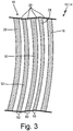
- FIG. 3 is a schematic diagram of an alternative configuration of the heater system 18.
- heater system 18 includes third heater layer 58, fourth heater layer 60, and fifth heater layer 62.
- Film adhesive and insulation 26 is found between each of the heater layers (58, 60, and 62), between probe surface 16 and third heater layer 58, and between probe sleeve 20 and fifth heater layer 62.
- Third heater layer 58 includes CNT heater 28.
- Fourth heater layer 60 includes PTC heater 30.
- Fifth heater layer 62 includes PTC heater 32.
- Third heater layer 58 and fourth heater layer 60 are wired in parallel to form parallel formation 48 (as shown in FIG. 2C ).
- Fifth heater layer 62 is wired in series with voltage source 46 and parallel formation 48.
- CNT heater 28 is made from carbon nanotube and silicone composite, CNT heater 28 is more rigid and durable than PTC heater 30 and PTC heater 32. Therefore, in the configuration of heater system 18, CNT heater 28 should be in the outermost heater layer (e.g., third heater layer 58) so that CNT heater 28 can protected fourth heater layer 60 and fifth heater layer 62.
- first heater set 42 (as shown in FIG. 2C ) can be located within strut assembly 12 and second heater set 44 (as shown in FIG. 2C ) can be located within housing assembly 14.
- first heater set 42 and second heater set 44 can be wired in series with one another and voltage source 46.
- first heater set 42 is located within strut assembly 12 and second heater set 44 is located within housing assembly 14
- first heater set 42 and second heater set 44 each heating system can have dedicated voltage sources, and each system (first heater set 42 and second heater set 44) can be a standalone system independent of one another.
- FIGS. 4A and 4B will be discussed concurrently.
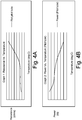
- FIG. 4A is a graph showing resistance as a function of temperature for heater system 18.
- FIG. 4B is a graph showing power as a function of temperature heater system 18.
- the graphs in FIGS 4A and 4B show the relationship discussed above in paragraphs [0024] and [0026] above.
- the resistance of the heater system is low when the temperature of the heater system is low.
- the resistance of the heater system increases as the temperature of the heater system increases.
- the power supplied to the overall heating system decreases as the temperature increases. Decreasing the power to the heating system prevents the heating system from overheating and conserves energy.
- a hybrid heater system for an aircraft air data sensor includes a voltage source and a first hybrid heater set.
- the first hybrid heater set includes a carbon nanotube (CNT) heater, a first positive temperature coefficient (PTC) heater disposed in parallel with the CNT heater to form a parallel formation, and a second PTC heater disposed in series between the voltage source and the parallel formation.
- CNT carbon nanotube
- PTC positive temperature coefficient
- hybrid heater system of the preceding paragraph can optionally include, additionally and/or alternatively, any one or more of the following features, configurations and/or additional components:
- a hybrid heater system for ice protection of an air data probe on an aircraft includes a voltage source, a carbon nanotube (CNT) heater, which includes CNT heater elements, a first positive temperature coefficient (PTC) heater disposed in parallel with the CNT heater to form a parallel formation, and a second PTC heater.
- the first PTC heater includes first PTC heater elements interleaved with the CNT heater elements in a first air data probe layer.
- the second PTC heater is disposed in a second air data probe layer and in series between the voltage source and the parallel formation.
- hybrid heater system of the preceding paragraph can optionally include, additionally and/or alternatively, any one or more of the following features, configurations and/or additional components:
- a method of making a heater for an air data probe includes positioning on the air data probe a first heater layer.
- the first heater layer includes a carbon nanotube (CNT) heater element and a first positive temperature coefficient (PTC) heater element interleaved with one another.
- the method of heating an air data probe further includes positioning on the air data probe a second heater layer.
- the second heater layer includes a second PTC heater element.
- the method of heating an air data probe further includes wiring the first heater layer and the second heater layer so that the CNT heater element and the first PTC heater element are in parallel with one another defining a parallel formation.
- the method of heating an air data probe further includes wiring the second heater layer so that the second PTC heater element is in series with the first parallel formation and a voltage source.
- the method of the preceding paragraph can optionally include, additionally and/or alternatively, any one or more of the following features, configurations and/or additional components:
Landscapes
- Engineering & Computer Science (AREA)
- Aviation & Aerospace Engineering (AREA)
- Physics & Mathematics (AREA)
- General Physics & Mathematics (AREA)
- Resistance Heating (AREA)
- Thermistors And Varistors (AREA)
Applications Claiming Priority (1)
| Application Number | Priority Date | Filing Date | Title |
|---|---|---|---|
| IN202041012145 | 2020-03-20 |
Publications (2)
| Publication Number | Publication Date |
|---|---|
| EP3883337A1 true EP3883337A1 (de) | 2021-09-22 |
| EP3883337B1 EP3883337B1 (de) | 2025-12-10 |
Family
ID=75108237
Family Applications (1)
| Application Number | Title | Priority Date | Filing Date |
|---|---|---|---|
| EP21163469.6A Active EP3883337B1 (de) | 2020-03-20 | 2021-03-18 | Dünnschichtheizungskonfiguration für eine luftdatensonde |
Country Status (4)
| Country | Link |
|---|---|
| US (1) | US11745879B2 (de) |
| EP (1) | EP3883337B1 (de) |
| BR (1) | BR102021001713A2 (de) |
| CA (1) | CA3109793A1 (de) |
Families Citing this family (3)
| Publication number | Priority date | Publication date | Assignee | Title |
|---|---|---|---|---|
| US11425797B2 (en) * | 2019-10-29 | 2022-08-23 | Rosemount Aerospace Inc. | Air data probe including self-regulating thin film heater |
| US11745879B2 (en) | 2020-03-20 | 2023-09-05 | Rosemount Aerospace Inc. | Thin film heater configuration for air data probe |
| FR3165241A1 (fr) * | 2024-08-02 | 2026-02-06 | Thales | Dispositif de mesure aérodynamique |
Citations (2)
| Publication number | Priority date | Publication date | Assignee | Title |
|---|---|---|---|---|
| US4458137A (en) * | 1981-04-09 | 1984-07-03 | Rosemount Inc. | Electric heater arrangement for fluid flow stream sensors |
| US20200086999A1 (en) * | 2018-09-13 | 2020-03-19 | Goodrich Corporation | Hybrid heater for aircraft wing ice protection |
Family Cites Families (58)
| Publication number | Priority date | Publication date | Assignee | Title |
|---|---|---|---|---|
| US2254155A (en) | 1938-12-13 | 1941-08-26 | Bendix Aviat Corp | Pitot-static tube |
| US4121088A (en) | 1976-10-18 | 1978-10-17 | Rosemount Inc. | Electrically heated air data sensing device |
| GB8604519D0 (en) | 1986-02-24 | 1986-04-03 | Raychem Sa Nv | Electrical devices |
| FR2695203B1 (fr) | 1992-08-28 | 1994-11-04 | Intertechnique Sa | Détecteur de liquide à thermistance. |
| US5543183A (en) | 1995-02-17 | 1996-08-06 | General Atomics | Chromium surface treatment of nickel-based substrates |
| JPH09163593A (ja) * | 1995-12-05 | 1997-06-20 | Murata Mfg Co Ltd | 突入電流抑制回路 |
| US6070475A (en) | 1997-10-15 | 2000-06-06 | Rosemont Aerospace Inc. | Air data probe with heater means within wall |
| KR100786679B1 (ko) | 1999-05-14 | 2007-12-21 | 아숙 테크놀러지스 엘엘씨 | 전기 가열장치 및 리셋가능 퓨즈 |
| US6591696B2 (en) | 2001-07-12 | 2003-07-15 | Rosemount Aerospace, Inc. | Integral electric pressure probe for aircraft |
| GB0427650D0 (en) | 2004-12-17 | 2005-01-19 | Heat Trace Ltd | Electrical device |
| GB0428297D0 (en) | 2004-12-24 | 2005-01-26 | Heat Trace Ltd | Control of heating cable |
| KR100749886B1 (ko) | 2006-02-03 | 2007-08-21 | (주) 나노텍 | 탄소나노튜브를 이용한 발열체 |
| US7923668B2 (en) | 2006-02-24 | 2011-04-12 | Rohr, Inc. | Acoustic nacelle inlet lip having composite construction and an integral electric ice protection heater disposed therein |
| GB0609729D0 (en) | 2006-05-17 | 2006-06-28 | Heat Trace Ltd | Material and heating cable |
| WO2008002071A1 (en) | 2006-06-27 | 2008-01-03 | Naos Co., Ltd. | Method for manufacturing planar heating element using carbon micro-fibers |
| EP2069440B1 (de) | 2006-08-02 | 2011-09-28 | Battelle Memorial Institute | Elektrisch leitfähige beschichtungszusammensetzung |
| SE530660C2 (sv) | 2006-10-17 | 2008-08-05 | Conflux Ab | Värmeelement |
| GB0700079D0 (en) | 2007-01-04 | 2007-02-07 | Boardman Jeffrey | A method of producing electrical resistance elements whihc have self-regulating power output characteristics by virtue of their configuration and the material |
| US20080166563A1 (en) | 2007-01-04 | 2008-07-10 | Goodrich Corporation | Electrothermal heater made from thermally conducting electrically insulating polymer material |
| US20100116806A1 (en) | 2007-05-08 | 2010-05-13 | Honeywell International Inc. | Automated heating system for ports susceptible to icing |
| US8164035B2 (en) | 2008-04-17 | 2012-04-24 | Long-Huang Chang | Heating device having dual-core heating cable |
| US20100126985A1 (en) | 2008-06-13 | 2010-05-27 | Tsinghua University | Carbon nanotube heater |
| AT508327A1 (de) | 2008-07-29 | 2010-12-15 | Villinger Markus | Heizvorrichtung zum enteisen von luftfahrzeugteilen |
| GB0817082D0 (en) | 2008-09-18 | 2008-10-29 | Heat Trace Ltd | Heating cable |
| KR101328353B1 (ko) | 2009-02-17 | 2013-11-11 | (주)엘지하우시스 | 탄소나노튜브 발열시트 |
| US8664573B2 (en) | 2009-04-27 | 2014-03-04 | Applied Nanostructured Solutions, Llc | CNT-based resistive heating for deicing composite structures |
| DE102009034306B4 (de) | 2009-07-21 | 2015-07-23 | Fraunhofer-Gesellschaft zur Förderung der angewandten Forschung e.V. | Heizelement sowie Verfahren zu dessen Herstellung |
| US8496854B2 (en) | 2009-10-30 | 2013-07-30 | Sabic Innovative Plastics Ip B.V. | Positive temperature coefficient materials with reduced negative temperature coefficient effect |
| US9091657B2 (en) | 2010-01-26 | 2015-07-28 | Metis Design Corporation | Multifunctional CNT-engineered structures |
| US8481898B2 (en) * | 2010-06-04 | 2013-07-09 | Robert Parker | Self regulating electric heaters |
| EP2641451B1 (de) | 2010-11-17 | 2019-03-06 | Battelle Memorial Institute | Widerstandsheizung mit kohlenstoffnanoröhrchen-dünnschichtlaminat |
| KR101184780B1 (ko) | 2010-12-20 | 2012-09-20 | 한국항공우주연구원 | 적층 방식을 이용한 방빙형 피토 정압 프로브 제작방법 |
| EP3575218B1 (de) | 2010-12-31 | 2021-08-11 | Battelle Memorial Institute | Antenne mit schicht aus kohlenstoff-nanoröhrchen |
| DE102011119844A1 (de) * | 2011-05-26 | 2012-12-13 | Eads Deutschland Gmbh | Verbundstruktur mit Eisschutzvorrichtung sowie Herstellverfahren |
| CA2813551C (en) | 2012-04-20 | 2018-10-30 | Goodrich Corporation | Printed heating element |
| EP3000281A1 (de) | 2013-05-21 | 2016-03-30 | Heat Trace Limited | Elektrisches heizaggregat |
| US9884685B2 (en) | 2014-05-28 | 2018-02-06 | The Boeing Company | External case heater for an angle of attack sensor |
| US10373745B2 (en) | 2014-06-12 | 2019-08-06 | LMS Consulting Group | Electrically conductive PTC ink with double switching temperatures and applications thereof in flexible double-switching heaters |
| KR101602880B1 (ko) | 2014-06-18 | 2016-03-11 | (주)유니플라텍 | 고분자 수계 에멀전 전도성 조성물을 이용한 피티씨 소자의 제조 방법과, 그 제조 방법에 의해 제조된 피티씨 소자 및 그 피티씨 소자가 구비된 면상 발열체 |
| US10440829B2 (en) | 2014-07-03 | 2019-10-08 | United Technologies Corporation | Heating circuit assembly and method of manufacture |
| EP4120796A3 (de) | 2015-01-06 | 2023-05-03 | Battelle Memorial Institute | Gleichmässige wärmeverteilung in widerstandsheizern für frostschutz und enteisung |
| WO2016144683A1 (en) | 2015-03-06 | 2016-09-15 | Sikorsky Aircraft Corporation | Heating design for rotorcraft blade de-icing and anti-icing |
| DE102015107316B4 (de) | 2015-05-11 | 2023-10-12 | Borgwarner Ludwigsburg Gmbh | Elektrische Heizvorrichtung |
| US9668301B2 (en) | 2015-07-03 | 2017-05-30 | Ndt Engineering & Aerospace Co., Ltd. | Wet-use plane heater using PTC constant heater-ink polymer |
| DE102016209012A1 (de) | 2015-12-18 | 2017-06-22 | E.G.O. Elektro-Gerätebau GmbH | Heizeinrichtung |
| US9719820B1 (en) | 2016-01-29 | 2017-08-01 | Goodrich Aerospace Services Private Limited | Hybrid material pitot tube |
| CA2964260C (en) | 2016-06-28 | 2025-08-26 | Rosemount Aerospace Inc. | AIR DATA DETECTION PROBE USING AN ICING STATE DETECTOR |
| US10368394B2 (en) | 2016-09-01 | 2019-07-30 | Hamilton Sundstrand Corporation | PTC heater with autonomous control |
| US20180112938A1 (en) | 2016-10-26 | 2018-04-26 | Goodrich Aerospace Services Private Limited | Die-cast bodies with thermal conductive inserts |
| US11297692B2 (en) | 2016-11-01 | 2022-04-05 | Goodrich Corporation | Multilayered panels |
| US10197588B2 (en) | 2016-11-09 | 2019-02-05 | Honeywell International Inc. | Thin film heating systems for air data probes |
| US11382181B2 (en) | 2016-12-02 | 2022-07-05 | Goodrich Corporation | Method to create carbon nanotube heaters with varying resistance |
| US10578637B2 (en) | 2018-06-15 | 2020-03-03 | Rosemount Aerospace Inc. | Integration of low ice adhesion surface coatings with air data probes |
| US11167856B2 (en) | 2018-12-13 | 2021-11-09 | Goodrich Corporation Of Charlotte, Nc | Multilayer structure with carbon nanotube heaters |
| CN109683642A (zh) | 2019-02-03 | 2019-04-26 | 元能机械科技(上海)有限公司 | 具有感应加热的空气数据探头及其温度控制方法 |
| US11585826B2 (en) | 2019-07-19 | 2023-02-21 | Rosemount Aerospace Inc. | Thin film heater on a sleeve outer surface in a strut portion and/or a probe head of an air data probe |
| US11425797B2 (en) | 2019-10-29 | 2022-08-23 | Rosemount Aerospace Inc. | Air data probe including self-regulating thin film heater |
| US11745879B2 (en) | 2020-03-20 | 2023-09-05 | Rosemount Aerospace Inc. | Thin film heater configuration for air data probe |
-
2020
- 2020-06-17 US US16/903,686 patent/US11745879B2/en active Active
-
2021
- 2021-01-29 BR BR102021001713-9A patent/BR102021001713A2/pt unknown
- 2021-02-19 CA CA3109793A patent/CA3109793A1/en active Pending
- 2021-03-18 EP EP21163469.6A patent/EP3883337B1/de active Active
Patent Citations (2)
| Publication number | Priority date | Publication date | Assignee | Title |
|---|---|---|---|---|
| US4458137A (en) * | 1981-04-09 | 1984-07-03 | Rosemount Inc. | Electric heater arrangement for fluid flow stream sensors |
| US20200086999A1 (en) * | 2018-09-13 | 2020-03-19 | Goodrich Corporation | Hybrid heater for aircraft wing ice protection |
Also Published As
| Publication number | Publication date |
|---|---|
| BR102021001713A2 (pt) | 2021-10-05 |
| US11745879B2 (en) | 2023-09-05 |
| CA3109793A1 (en) | 2021-09-20 |
| EP3883337B1 (de) | 2025-12-10 |
| US20210291992A1 (en) | 2021-09-23 |
Similar Documents
| Publication | Publication Date | Title |
|---|---|---|
| EP3883337B1 (de) | Dünnschichtheizungskonfiguration für eine luftdatensonde | |
| EP2004488B1 (de) | Eisschutzsystem | |
| EP3816634B1 (de) | Luftdatensonde mit selbstregulierender dünnfilmheizvorrichtung | |
| US8481898B2 (en) | Self regulating electric heaters | |
| CA1182158A (en) | Fluid flow stream sensor heater | |
| EP1997731A2 (de) | Automatisiertes Erwärmungssystem für vereisungsanfällige Anschlüsse | |
| JP6069734B2 (ja) | 車両ヒータの製造方法および車両ヒータ | |
| CA2580163A1 (en) | Adaptable layered heater system | |
| US11235881B2 (en) | Hybrid heater for aircraft wing ice protection | |
| CN110636651B (zh) | 具有低漂移电阻反馈的电加热器 | |
| EP2613158A1 (de) | Keramische Heizvorrichtung | |
| CN111328159A (zh) | 具有碳纳米管加热器的多层结构 | |
| JP2015514860A5 (de) | ||
| CN109683642A (zh) | 具有感应加热的空气数据探头及其温度控制方法 | |
| JP2013026222A (ja) | 加熱システム、ヒーター、および部品を加熱する方法 | |
| EP3836747A1 (de) | Konforme dünnschichtheizelemente für anstellwinkelsensoren | |
| EP3595404A1 (de) | Multipolymere erwärmung mit positivem temperaturkoeffizienten | |
| EP3401617A1 (de) | Elektrische heizeinrichtung | |
| CN115478930B (zh) | 排气加热器 | |
| US7934491B2 (en) | Heater module for the admission gases of an automobile engine with an overheating protection and/or closed-loop regulation | |
| CN114007288A (zh) | 一种用于直升机尾桨叶防冰的ptc柔性加热膜及加热组件 | |
| JPS6032958B2 (ja) | 感熱体 | |
| JP2004363264A (ja) | 抵抗体素子 | |
| JPH10318852A (ja) | ヒューズ機能付き過熱検知用温度センサ | |
| JPH0398284A (ja) | 発熱装置 |
Legal Events
| Date | Code | Title | Description |
|---|---|---|---|
| PUAI | Public reference made under article 153(3) epc to a published international application that has entered the european phase |
Free format text: ORIGINAL CODE: 0009012 |
|
| STAA | Information on the status of an ep patent application or granted ep patent |
Free format text: STATUS: THE APPLICATION HAS BEEN PUBLISHED |
|
| AK | Designated contracting states |
Kind code of ref document: A1 Designated state(s): AL AT BE BG CH CY CZ DE DK EE ES FI FR GB GR HR HU IE IS IT LI LT LU LV MC MK MT NL NO PL PT RO RS SE SI SK SM TR |
|
| STAA | Information on the status of an ep patent application or granted ep patent |
Free format text: STATUS: REQUEST FOR EXAMINATION WAS MADE |
|
| 17P | Request for examination filed |
Effective date: 20220322 |
|
| RBV | Designated contracting states (corrected) |
Designated state(s): AL AT BE BG CH CY CZ DE DK EE ES FI FR GB GR HR HU IE IS IT LI LT LU LV MC MK MT NL NO PL PT RO RS SE SI SK SM TR |
|
| STAA | Information on the status of an ep patent application or granted ep patent |
Free format text: STATUS: EXAMINATION IS IN PROGRESS |
|
| 17Q | First examination report despatched |
Effective date: 20220914 |
|
| GRAP | Despatch of communication of intention to grant a patent |
Free format text: ORIGINAL CODE: EPIDOSNIGR1 |
|
| STAA | Information on the status of an ep patent application or granted ep patent |
Free format text: STATUS: GRANT OF PATENT IS INTENDED |
|
| INTG | Intention to grant announced |
Effective date: 20250226 |
|
| GRAJ | Information related to disapproval of communication of intention to grant by the applicant or resumption of examination proceedings by the epo deleted |
Free format text: ORIGINAL CODE: EPIDOSDIGR1 |
|
| STAA | Information on the status of an ep patent application or granted ep patent |
Free format text: STATUS: EXAMINATION IS IN PROGRESS |
|
| GRAP | Despatch of communication of intention to grant a patent |
Free format text: ORIGINAL CODE: EPIDOSNIGR1 |
|
| STAA | Information on the status of an ep patent application or granted ep patent |
Free format text: STATUS: GRANT OF PATENT IS INTENDED |
|
| INTC | Intention to grant announced (deleted) | ||
| INTG | Intention to grant announced |
Effective date: 20250704 |
|
| GRAS | Grant fee paid |
Free format text: ORIGINAL CODE: EPIDOSNIGR3 |
|
| GRAA | (expected) grant |
Free format text: ORIGINAL CODE: 0009210 |
|
| STAA | Information on the status of an ep patent application or granted ep patent |
Free format text: STATUS: THE PATENT HAS BEEN GRANTED |
|
| AK | Designated contracting states |
Kind code of ref document: B1 Designated state(s): AL AT BE BG CH CY CZ DE DK EE ES FI FR GB GR HR HU IE IS IT LI LT LU LV MC MK MT NL NO PL PT RO RS SE SI SK SM TR |
|
| REG | Reference to a national code |
Ref country code: CH Ref legal event code: F10 Free format text: ST27 STATUS EVENT CODE: U-0-0-F10-F00 (AS PROVIDED BY THE NATIONAL OFFICE) Effective date: 20251210 Ref country code: GB Ref legal event code: FG4D |
|
| REG | Reference to a national code |
Ref country code: DE Ref legal event code: R096 Ref document number: 602021043964 Country of ref document: DE |
|
| REG | Reference to a national code |
Ref country code: IE Ref legal event code: FG4D |