EP3883171A1 - Procédé et appareil de transmissions à faible latence - Google Patents
Procédé et appareil de transmissions à faible latence Download PDFInfo
- Publication number
- EP3883171A1 EP3883171A1 EP21172654.2A EP21172654A EP3883171A1 EP 3883171 A1 EP3883171 A1 EP 3883171A1 EP 21172654 A EP21172654 A EP 21172654A EP 3883171 A1 EP3883171 A1 EP 3883171A1
- Authority
- EP
- European Patent Office
- Prior art keywords
- subframe
- time
- low latency
- frequency resources
- data
- Prior art date
- Legal status (The legal status is an assumption and is not a legal conclusion. Google has not performed a legal analysis and makes no representation as to the accuracy of the status listed.)
- Granted
Links
- 230000005540 biological transmission Effects 0.000 title claims abstract description 348
- 238000000034 method Methods 0.000 title claims abstract description 68
- 239000003550 marker Substances 0.000 claims description 165
- 230000011664 signaling Effects 0.000 claims description 32
- 108091006146 Channels Proteins 0.000 description 209
- 239000010410 layer Substances 0.000 description 117
- 230000002123 temporal effect Effects 0.000 description 97
- 230000002776 aggregation Effects 0.000 description 56
- 238000004220 aggregation Methods 0.000 description 56
- 238000012544 monitoring process Methods 0.000 description 35
- 238000004891 communication Methods 0.000 description 30
- 230000004044 response Effects 0.000 description 18
- 230000015654 memory Effects 0.000 description 16
- 101000741965 Homo sapiens Inactive tyrosine-protein kinase PRAG1 Proteins 0.000 description 12
- 102100038659 Inactive tyrosine-protein kinase PRAG1 Human genes 0.000 description 12
- 125000004122 cyclic group Chemical group 0.000 description 10
- 230000002829 reductive effect Effects 0.000 description 9
- 238000013468 resource allocation Methods 0.000 description 9
- 230000008901 benefit Effects 0.000 description 8
- 238000013507 mapping Methods 0.000 description 7
- 230000006870 function Effects 0.000 description 6
- 230000008569 process Effects 0.000 description 5
- 238000012545 processing Methods 0.000 description 5
- 239000000969 carrier Substances 0.000 description 4
- 238000010586 diagram Methods 0.000 description 4
- 230000000873 masking effect Effects 0.000 description 4
- 230000009471 action Effects 0.000 description 3
- 230000000903 blocking effect Effects 0.000 description 3
- 230000008859 change Effects 0.000 description 3
- 238000001514 detection method Methods 0.000 description 3
- 230000003287 optical effect Effects 0.000 description 3
- 230000002093 peripheral effect Effects 0.000 description 3
- 230000009467 reduction Effects 0.000 description 3
- 206010009944 Colon cancer Diseases 0.000 description 2
- 230000002411 adverse Effects 0.000 description 2
- 238000013459 approach Methods 0.000 description 2
- 230000001413 cellular effect Effects 0.000 description 2
- 230000001419 dependent effect Effects 0.000 description 2
- 230000000670 limiting effect Effects 0.000 description 2
- 230000007774 longterm Effects 0.000 description 2
- 230000002085 persistent effect Effects 0.000 description 2
- 230000007480 spreading Effects 0.000 description 2
- 210000003813 thumb Anatomy 0.000 description 2
- 238000012546 transfer Methods 0.000 description 2
- 230000000007 visual effect Effects 0.000 description 2
- 238000013500 data storage Methods 0.000 description 1
- 238000013461 design Methods 0.000 description 1
- 230000009977 dual effect Effects 0.000 description 1
- 239000002355 dual-layer Substances 0.000 description 1
- 230000000694 effects Effects 0.000 description 1
- 238000005516 engineering process Methods 0.000 description 1
- 230000006872 improvement Effects 0.000 description 1
- 239000004973 liquid crystal related substance Substances 0.000 description 1
- 238000005259 measurement Methods 0.000 description 1
- 230000007246 mechanism Effects 0.000 description 1
- 238000012986 modification Methods 0.000 description 1
- 230000004048 modification Effects 0.000 description 1
- 230000001902 propagating effect Effects 0.000 description 1
- 230000004043 responsiveness Effects 0.000 description 1
- 230000002441 reversible effect Effects 0.000 description 1
- 230000011218 segmentation Effects 0.000 description 1
- 230000008054 signal transmission Effects 0.000 description 1
- 239000007787 solid Substances 0.000 description 1
Images


Classifications
-
- H—ELECTRICITY
- H04—ELECTRIC COMMUNICATION TECHNIQUE
- H04L—TRANSMISSION OF DIGITAL INFORMATION, e.g. TELEGRAPHIC COMMUNICATION
- H04L1/00—Arrangements for detecting or preventing errors in the information received
- H04L1/12—Arrangements for detecting or preventing errors in the information received by using return channel
- H04L1/16—Arrangements for detecting or preventing errors in the information received by using return channel in which the return channel carries supervisory signals, e.g. repetition request signals
- H04L1/18—Automatic repetition systems, e.g. Van Duuren systems
- H04L1/1829—Arrangements specially adapted for the receiver end
- H04L1/1854—Scheduling and prioritising arrangements
-
- H—ELECTRICITY
- H04—ELECTRIC COMMUNICATION TECHNIQUE
- H04L—TRANSMISSION OF DIGITAL INFORMATION, e.g. TELEGRAPHIC COMMUNICATION
- H04L1/00—Arrangements for detecting or preventing errors in the information received
- H04L1/12—Arrangements for detecting or preventing errors in the information received by using return channel
- H04L1/16—Arrangements for detecting or preventing errors in the information received by using return channel in which the return channel carries supervisory signals, e.g. repetition request signals
- H04L1/18—Automatic repetition systems, e.g. Van Duuren systems
- H04L1/1867—Arrangements specially adapted for the transmitter end
- H04L1/1896—ARQ related signaling
-
- H—ELECTRICITY
- H04—ELECTRIC COMMUNICATION TECHNIQUE
- H04L—TRANSMISSION OF DIGITAL INFORMATION, e.g. TELEGRAPHIC COMMUNICATION
- H04L41/00—Arrangements for maintenance, administration or management of data switching networks, e.g. of packet switching networks
- H04L41/08—Configuration management of networks or network elements
- H04L41/0803—Configuration setting
-
- H—ELECTRICITY
- H04—ELECTRIC COMMUNICATION TECHNIQUE
- H04L—TRANSMISSION OF DIGITAL INFORMATION, e.g. TELEGRAPHIC COMMUNICATION
- H04L43/00—Arrangements for monitoring or testing data switching networks
- H04L43/08—Monitoring or testing based on specific metrics, e.g. QoS, energy consumption or environmental parameters
- H04L43/0852—Delays
- H04L43/087—Jitter
-
- H—ELECTRICITY
- H04—ELECTRIC COMMUNICATION TECHNIQUE
- H04L—TRANSMISSION OF DIGITAL INFORMATION, e.g. TELEGRAPHIC COMMUNICATION
- H04L5/00—Arrangements affording multiple use of the transmission path
- H04L5/003—Arrangements for allocating sub-channels of the transmission path
-
- H—ELECTRICITY
- H04—ELECTRIC COMMUNICATION TECHNIQUE
- H04L—TRANSMISSION OF DIGITAL INFORMATION, e.g. TELEGRAPHIC COMMUNICATION
- H04L5/00—Arrangements affording multiple use of the transmission path
- H04L5/003—Arrangements for allocating sub-channels of the transmission path
- H04L5/0044—Arrangements for allocating sub-channels of the transmission path allocation of payload
-
- H—ELECTRICITY
- H04—ELECTRIC COMMUNICATION TECHNIQUE
- H04L—TRANSMISSION OF DIGITAL INFORMATION, e.g. TELEGRAPHIC COMMUNICATION
- H04L5/00—Arrangements affording multiple use of the transmission path
- H04L5/003—Arrangements for allocating sub-channels of the transmission path
- H04L5/0053—Allocation of signaling, i.e. of overhead other than pilot signals
- H04L5/0055—Physical resource allocation for ACK/NACK
-
- H—ELECTRICITY
- H04—ELECTRIC COMMUNICATION TECHNIQUE
- H04L—TRANSMISSION OF DIGITAL INFORMATION, e.g. TELEGRAPHIC COMMUNICATION
- H04L5/00—Arrangements affording multiple use of the transmission path
- H04L5/0091—Signaling for the administration of the divided path
-
- H—ELECTRICITY
- H04—ELECTRIC COMMUNICATION TECHNIQUE
- H04L—TRANSMISSION OF DIGITAL INFORMATION, e.g. TELEGRAPHIC COMMUNICATION
- H04L69/00—Network arrangements, protocols or services independent of the application payload and not provided for in the other groups of this subclass
- H04L69/30—Definitions, standards or architectural aspects of layered protocol stacks
- H04L69/32—Architecture of open systems interconnection [OSI] 7-layer type protocol stacks, e.g. the interfaces between the data link level and the physical level
- H04L69/322—Intralayer communication protocols among peer entities or protocol data unit [PDU] definitions
- H04L69/329—Intralayer communication protocols among peer entities or protocol data unit [PDU] definitions in the application layer [OSI layer 7]
-
- H—ELECTRICITY
- H04—ELECTRIC COMMUNICATION TECHNIQUE
- H04W—WIRELESS COMMUNICATION NETWORKS
- H04W72/00—Local resource management
- H04W72/04—Wireless resource allocation
- H04W72/044—Wireless resource allocation based on the type of the allocated resource
-
- H—ELECTRICITY
- H04—ELECTRIC COMMUNICATION TECHNIQUE
- H04W—WIRELESS COMMUNICATION NETWORKS
- H04W72/00—Local resource management
- H04W72/04—Wireless resource allocation
- H04W72/044—Wireless resource allocation based on the type of the allocated resource
- H04W72/0446—Resources in time domain, e.g. slots or frames
-
- H—ELECTRICITY
- H04—ELECTRIC COMMUNICATION TECHNIQUE
- H04W—WIRELESS COMMUNICATION NETWORKS
- H04W72/00—Local resource management
- H04W72/20—Control channels or signalling for resource management
Definitions
- the devices 110 and 112 can be UE's, such as wireless terminals, portable wireless communication devices, stationary wireless communication devices, smartphones, cellular telephones, flip phones, personal digital assistants, personal computers having cellular network access cards, selective call receivers, tablet computers, or any other devices that are capable of operating on a wireless network.
- UE's such as wireless terminals, portable wireless communication devices, stationary wireless communication devices, smartphones, cellular telephones, flip phones, personal digital assistants, personal computers having cellular network access cards, selective call receivers, tablet computers, or any other devices that are capable of operating on a wireless network.
- a resource block can span a slot or 7 OFDM symbols for a normal cyclic prefix length such that two RBs (or a single RB pair) span the subframe.
- the number of data OFDM symbols in the first RB corresponding to the first slot of a subframe can be shortened by the number of OFDM control symbols allocated.
- the user equipment can attempt to decode control channel and low latency data transmissions in the control region.
- the user equipment can identify a control channel based on a first RNTI (e.g., C-RNTI) and low latency data packets based on a second RNTI (e.g., LL-RNTI).
- a first RNTI e.g., C-RNTI
- second RNTI e.g., LL-RNTI
- a user equipment may monitor low latency control channel (e.g., LL-PDCCH) candidates with a DCI that contains the resource assignment for a low latency data packet.
- the low latency data packet may be transmitted in a data region from one or more data regions in a subframe.
- the low latency data packet can be transmitted in a data region associated with or based on the location of the control channel that contains the resource assignment for the low latency data packet.
- a particular user equipment may locate the resource elements corresponding to each low latency data channel candidate it is to monitor (blindly decode for each subframe control region).
- the CRC of each low latency data channel may be typically masked by a unique identifier corresponding to the user equipment that the base unit is trying to schedule. In other embodiments the CRC may be masked with a common identifier for all low latency data packets or low latency data packet receiving user equipments.
- the unique identifier can be assigned to the UE by its serving base station. In one embodiment, this identifier can be known as a Radio Network Temporary Identifier (RNTI) and the one normally assigned to each UE at call admission can be the Low Latency RNTI or LL-RNTI.
- RNTI Radio Network Temporary Identifier
- a UE may also be assigned a semi-persistent-scheduling C-RNTI (SPS C-RNTI) or a temporary C-RNTI (TC-RNTI) and a cell specific C-RNTI.
- SPS C-RNTI semi-persistent-scheduling C-RNTI
- TC-RNTI temporary C-RNTI
- a UE decodes resource elements corresponding to a low latency data packet, it can apply its LL-RNTI in the form of a mask to the low latency data packet CRC for successful decoding to occur.
- a UE successfully decodes a low latency data packet meant for it it can then send it to the application layer for use by the appropriate service needing low latency transmission.
- the UE may need to attempt to descramble the decoded packet in order to determine that the packet is meant for it.
- Channel coding e.g., convolutional coding
- different masking of the scrambled CRC can be used or instead an extra bit in the PDCCH payload itself can be used to distinguish between same size PDCCH DCI formats (e.g. DCI format 0 and 1A).
- An example includes, but is not limited to, the case of broadcast control which uses SI-RNTI, P-RNTI, or RA-RNTI for DCI format 1A instead of C-RNTI.
- the UE search space may support 4 aggregation levels including (1, 2, 4, or 8) logically contiguous CCEs per PDCCH (candidate) hypothesis and low latency data candidates with (6,6,2,2) blind detection locations, for each of the aggregation levels respectively.
- Equation (1) can randomize the candidate hypothesis CCE locations per aggregation level search space to minimize blocking.
- a UE can performs a convolutional coding blind detection (CCBD) for DCI format types for PDCCH and low latency data at the corresponding aggregation level for the candidate hypothesis.
- CCBD convolutional coding blind detection
- the blind decoding can allow the base station to dynamically select the aggregation size based on for example the channel conditions such that a large number of CCEs need not be used all of the time.
- FIG. 2 is an example illustration 200 of subframes n through n+4 according to a possible embodiment.
- the subframe n can include a first region 210, such as a control region, and a second region 220, such as a data region.
- the first region 210 can include resource elements 230.
- a resource element (RE) can represent a single subcarrier for a single OFDM symbol period in the subframe. More generally, a resource element can be a smallest identifiable time/frequency/code/spatial domain resource unit within the subframe.
- Data packets such as low latency data packets or other data packets, can be mapped to at least one resource element of the resource elements 230.
- a device can receive a higher layer configuration message, where the higher layer can be higher than a physical layer.
- the higher layer message can be a dedicated mode RRC (Radio Resource Control) message sent to the device. In some embodiments it can be sent through broadcast system information message to all devices in a cell.
- the device can determine, based on the higher layer configuration message, a first region of a subframe for receiving data packets.
- the first region in the subframe can correspond to a set of time-domain resources in the subframe, such as OFDM symbols durations.
- the first region of the subframe can correspond to a set of frequency-domain resources in the subframe such as Resource Blocks (RBs) where each resource block can comprise a set of OFDM sub-carriers.
- RBs Resource Blocks
- the first region of the subframe can correspond to a set of Resource Elements (REs).
- the first region of the subframe can correspond to a set of Control Channel Elements (CCEs), where each control channel element can correspond to a set of resource elements or set of Resource Element Groups (REGs) within the subframe.
- the first region can include a first set of REs, where the first set of REs can be a subset of a second set of REs in the first region.
- the second set of resource elements can correspond to all the resource elements in the first region of the subframe on which the device can expect to receive control channels.
- the control channels can be channels such a Physical Downlink Control Channel (PDCCH) or Enhanced Physical Downlink Control Channel (EPDCCH).
- PDCH Physical Downlink Control Channel
- EPDCCH Enhanced Physical Downlink Control Channel
- the second set of resource elements can correspond to all the resource elements in the first region of the subframe on which the device can expect to receive control channels and acknowledgement signalling.
- the control channels can be channels such as PDCCH and EPDCCH.
- the acknowledgement signalling can be channels, such as Physical Hybrid-ARQ Indicator Channel (PHICH).
- the second set of resource elements can correspond to all the resource elements in the first region of the subframe.
- the first region can be used for control channel monitoring. Data packets can be mapped to (or transmitted on) at least one RE of the first set of REs.
- the device can monitor the first region, where monitoring can include attempting to decode the data packets in the first region. Attempting to decode can include blind decoding by the device.
- a CCE size of 72 REs (or 18 REGs where each REG has 4 data REs) can be used while, for monitoring control channels, a CCE size of 36 REs (or 9 REGs where each REG has 4 data REs) can be used.
- the DCI format size(s) of the low latency DCI format(s) can be same as one of the DCI format sizes used for control channel monitoring.
- DCI format LL1 can be same size as DCI Format 1A
- DCI Format LL2 can be same size as one of the transmission mode specific DCI formats.
- DCI Format LL2 will have same size as DCI Format 1
- DCI Format LL2 will have same size as DCI Format 2D.
- Transmission of data in the control region is especially suitable for small data packet sizes, such as 8-500 bits.
- the LL data information (LDI or LL DCI) monitored in the first region can be distinguished from the DCI of the control channels monitored in the same region based on Cyclic Redundancy Check (CRC) masking with different CRC masks. This is especially suitable when the DCI format size(s) of the low latency DCI format(s) are same as one of the DCI format sizes used for control channel monitoring.
- CRC Cyclic Redundancy Check
- the device may assume that the CRC of the DCI is encoded or scrambled with a device specific identifier, for example a Cell-Radio Network Temporary Identifier (C-RNTI); or a common identifier, for example a Paging-Radio Network Temporary Identifier (P-RNTI).
- C-RNTI Cell-Radio Network Temporary Identifier
- P-RNTI Paging-Radio Network Temporary Identifier
- the device may assume that the CRC of the payload of the LL data packet is encoded with a special identifier associated with LL data monitoring, for example a Low Latency -Radio Network Temporary Identifier (LL-RNTI).
- LL-RNTI Low Latency -Radio Network Temporary Identifier
- the CCEs or groups of REs from the second set of REs monitored by the device for control signalling can be associated with control channels such as PDCCH or EPDCCH.
- the CCEs or groups of REs in the first set monitored by the device for LL data can be associated with a separate physical channel using which low latency data is received (e.g. LL-PDSCH).
- groups of REs in the first set monitored by the device for LL data can be referred by a name other than 'CCEs' such as Low latency Channel Elements (LCEs).
- LCEs Low latency Channel Elements
- the CCEs monitored by the device for LL Data can still be associated with a control channel such as PDCCH or EPDCCH, but the information decoded on the CCEs, i.e., the DCI or LDI, is associated with a data channel such as PDSCH.
- feedback in response to decoding LL data can be sent in a subframe earlier than subframe n+4, such as subframe n+2, in response to LL data packets decoded in the first region of a subframe n.
- a device may be configured via higher layers with a low-latency transmission mode or a low-latency feature.
- the first region can be a control region corresponding to the first 1-3 OFDM symbols of a 1ms TTI. Since the region is in the beginning portion of the subframe, the LL data sent there can be decoded much earlier.
- the decoding can start when the device receives 3 OFDM symbols (if the LL data is sent in control region) rather than after device receives all 14 OFDM symbols (if the LL data were to be sent in regular manner, such as using PDSCH RBs that span till the end of the subframe that are assigned via DCI in PDCCH/EPDCCH) of a 1ms TTI. Due to this early decoding benefit, the device can then transmit the feedback earlier, such as in subframe n+2, or in latter half of subframe n+1. If the payload for LL data is small, such as around 100 bits or so the control channel decoder implemented in devices can also take advantage of the smaller payload to complete the decoding early.
- a first region such as a control channel region of a LTE subframe
- a first region can be used to define a new resource allocation design in support of low latency packet transmission and can be used for a control channel for normal or regular latency packet transmission.
- the device can be configured with a first set of RE's within the control channel region and the device can then blindly decode data packets using this first set of RE's.
- Downlink latency can be reduced in multiple ways in conjunction with a legacy frame structure, such as the LTE Rel-8 frame structure, where a legacy Transmission Time Interval (TTI) can have a 1ms duration, the legacy subframe can be 1ms, and a legacy slot can be 0.5ms.
- TTI Transmission Time Interval
- the system 100 can be simultaneously run with at least two different TTI durations, a legacy 1 ms TTI duration and at least one new TTI duration, such as 0.5 ms.
- Embodiments can provide faster processing time and faster Hybrid Automatic Repeat Request (HARQ) feedback transmission, such as where a HARQ Acknowledgement (HARQ-ACK) can be sent faster than 4 TTI's later, such as earlier than subframe n+4 after subframe n.
- HARQ-ACK Hybrid Automatic Repeat Request
- an ACK/NACK can be sent in subframe n+2, instead of n+4.
- Embodiments can also provide for faster Channel Quality Indicator (CQI) transmission, reduced TTI duration for packet transmission, such as using 0.5 ms TTI, and reduced TTI duration for feedback transmission, such as using 0.5 ms TTI.
- CQI Channel Quality Indicator
- TDD Time Division Duplex
- PDSCH Physical Downlink Shared Channel
- an uplink ACK/NACK resource can be assigned in each n+2 or n+4 timing.
- a UE in the downlink, may be configured with a transmission mode from a plurality of transmission modes for PDSCH reception, such as transmission mode 1-10 in Rel-12 LTE.
- a transmission mode can be associated with one or more PDSCH transmission scheme.
- a PDSCH transmission scheme may be, for example, a single antenna port transmission, transmit diversity, closed loop spatial multiplexing, open loop spatial multiplexing, large delay cyclic delay diversity, dual or a plurality of antenna ports transmission schemes.
- Some transmission schemes support transmission of only a single transport block in a TTI (such as a subframe), while some other transmission scheme support up to two transport blocks in a TTI.
- the reference signal or pilot signal associated with a transmission scheme for PDSCH demodulation may be a Common Reference Signal (CRS) or a UE-specific or dedicated DeModulation Reference Signal (DM-RS).
- a transmission scheme may be associated with a Downlink Control Information (DCI) format of a given payload size which includes the resource assignment and other control information for decoding the PDSCH.
- the DCI format may be transmitted on a PDCCH (Physical Downlink Control Channel) or an EPDCCH (Enhanced PDCCH) which includes CRC (Cyclic Redundancy Check) bits which may be scrambled by a particular C-RNTI configured for the device.
- PDCCH Physical Downlink Control Channel
- EPDCCH Enhanced PDCCH
- CRC Cyclic Redundancy Check
- a UE may be configured a transmission mode from a plurality of transmission modes for PUSCH (Physical Uplink Shared Channel) transmission, such as transmission mode 1-2 in Rel-12 LTE.
- PUSCH Physical Uplink Shared Channel
- the PUSCH transmission schemes may include single antenna port and closed loop spatial multiplexing transmission schemes.
- a device can be configured with a low-latency transmission mode, such as a low latency downlink control information format where transmission (Tx) HARQ ACK can be sent in subframe n+2 instead of n+4, there can be a Transport Block (TB) size restriction, there can be a Timing Advance (TA) restriction that can limit the configuration of the smaller latency to small(er) cells, there can be a dedicated PDSCH resource like in Semi Persistent Scheduling (SPS), where the ACK/NACK feedback can be similar to Rel-8, such as a dynamic ACK/NACK based on a Control Channel Element (CCE) index, and where there can be a small maximum Code Block (CB) size, such as 1500 bits instead of 6144 bits, which can improve pipelining and/or reduce complexity.
- a low-latency transmission mode such as a low latency downlink control information format where transmission (Tx) HARQ ACK can be sent in subframe n+2 instead of n+4, there can be a
- a maximum Code Block (CB) size can correspond to the largest information payload size that can be channel encoded for transmission on a particular physical channel, such as PDSCH before the information payload is segmented in to multiple code blocks.
- a transport block can include one or more code blocks.
- a device may be configured via higher layers with a low-latency transmission mode or a low-latency feature.
- the device may be required to transmit the HARQ feedback faster than a Rel-8 device, such as for a Downlink (DL) grant for PDSCH received in subframe n, the device may be required to transmit the corresponding HARQ-ACK feedback in subframe n+2 instead of subframe n+4.
- a Rel-8 device such as for a Downlink (DL) grant for PDSCH received in subframe n
- the device may be required to transmit the corresponding HARQ-ACK feedback in subframe n+2 instead of subframe n+4.
- This can imply that the device processing time for a PDSCH can be reduced from 3-TA to 1-TA.
- a dedicated PDCCH resource like in Semi-Persistent Scheduling (SPS), can be directly assigned to PDSCH. This can allow the device to start detecting and decoding the PDSCH early and to send the uplink feedback much faster.
- SPS Semi-Persistent Scheduling
- the device can be configured with a low latency DCI format that can work with any transmission mode. Up to three or more Orthogonal Frequency Multiplexed (OFDM) symbols can be used for a control region. Data can be sent on Control Channel Elements (CCE's) for small packets of data. An ACK can be sent in subframe n+2 is response to data on a Physical Downlink Control Channel (PDCCH).
- CCE's Control Channel Elements
- ACK can be sent in subframe n+2 is response to data on a Physical Downlink Control Channel (PDCCH).
- a device may be configured via higher layers with a low-latency transmission mode or a low-latency feature. For small packets, the PDSCH that typically occupies the entire 1ms TTI can instead be sent on CCE's comprising the PDCCH or control region.
- the data sent on the CCE's can be decoded much earlier, such as after a device receives 3 OFDM symbols rather than after device receives all 14 OFDM symbols of a 1ms TTI. Due to this early decoding benefit, the device can then transmit the uplink feedback earlier, such as in subframe n+2, or in slot 2 of subframe n+1.
- the typical payloads that can be sent can be around 100 bits or so, and they can take advantage of the control channel decoder implemented in devices.
- the PDSCH data can be distinguished from the DCI based on Cyclic Redundancy Check (CRC) masking with a different CRCs. This can allow for reduced complexity, no change to existing PDSCH structure, such as TTI duration, RS, mapping, etc., only HARQ timing may be modified, and small low-latency packets can be transmitted through a PDCCH structure.
- CRC Cyclic Redundancy Check
- FIG. 3 is an example illustration of a subframe 300 according to a related possible embodiment.
- the subframe 300 can include OFDM symbols 310 configured for low latency transmissions, resource blocks 320 configured for low latency transmissions, a first set of resource elements 330, such as first Low latency Channel Elements (LCE0), which can also be known as Data Channel Elements (DCE's), and a second set of resource elements 340, such as a second LCE1.
- the resource blocks configured for low latency transmissions may be localized physical resource blocks, localized virtual resource blocks, or distributed virtual resource blocks.
- the resource blocks configured for low latency transmissions may be defined in terms of Resource Block Groups (RBGs), localized VRBs from one or more RBG subsets, or distributed VRBs.
- RBG Resource Block Groups
- a RBG may be a set of consecutive virtual resource blocks (VRBs) of localized type.
- the Resource block group size ( P ) may be a function of the system bandwidth.
- a RBG subset p can include every P th RBG starting from RBG p.
- a LCE typically can include multiple REs and the REs corresponding to the LCE need not be contiguous in time or frequency domain.
- a LCE can also be spread out between multiple RBs and even spread out between multiple Resource Block Groups (RBGs) including multiple RBs.
- a LCE may comprise REs in a RBG in one or more OFDM symbols configured for low latency data packet transmission.
- a LCE may comprise REs in a subset of localized VRBs from one or more of the P RBG subsets in one or more OFDM symbols.
- the subset of localized VRBs may correspond to VRBs in different RBGs.
- a LCE may comprise REs in a subset of distributed VRBs in one or more OFDM symbols.
- the subset of distributed VRBs may be contiguous VRBs which as a result map to physical RBs that are distributed.
- a single symbol configured for low latency packet transmission can include multiple LCE's in different RB's configured for low latency packet transmission in the symbol.
- Low latency data packets can be on any of the symbols configured for low latency packet transmission, such as a subset of the symbols and can also be on a subset of RB's configured for low latency packet transmission.
- OFDM symbols 310 can be all the OFDM symbols in the subframe.
- RBs 320 can be all the RBs in the subframe.
- Some of the OFDM symbols 350 can include common reference signals, like pilot RE's, on some of the RE's in the symbols 350.
- L Low latency Data Information
- the set of aggregated LCEs from the subset of the LCEs at a particular LCE aggregation level, L can correspond to the set of low latency data candidates at the aggregation level L that the particular device monitors in a search space corresponding to subset of the LCEs at the particular LCE aggregation level, L.
- the device can monitor a set of low latency data candidates at a given aggregation level for low latency data packet where monitoring implies attempting to decode each of the low latency data candidates in the set according to all the monitored LDI formats.
- the device can determine successful decoding of data payload of a low latency data packet corresponding to a low latency data candidate by using an identifier associated with the UE such as C-RNTI or LL-RNTI which masks or scrambles the Cyclic Redundancy Check (CRC) of the data payload.
- a hashing function may be used to find the low latency data candidate locations in each search space. The hashing function may be based on the UE RNTI (identifier associated with the UE, such as C-RNTI or LL-RNTI), aggregation level (L), the total number of LCEs available (Nlce), the OFDM symbol number or index, and the maximum number of low latency data candidates for the search space.
- FIG. 4 is an example illustration of an OFDM symbol 400 according to a related possible embodiment.
- the OFDM symbol can be one of the OFDM symbols configured for low latency transmission in a subframe.
- the OFDM symbol 400 can include LCE's LCE0, LCE1, and LCE2, as well as other elements.
- the OFDM symbol 400 can have a bandwidth of RB's configured for low latency transmission, such as 12 RBs, 100 RBs, and other numbers of RB's.
- the LCE resources can optionally be used for marker transmission that can act as a type of control signal.
- a marker transmission can be an indicator channel that indicates whether the OFDM symbol is used for low latency traffic.
- the marker can also provide information indicating the REs or sets of REs (e.g.
- the marker transmission can be sent as a broadcast transmission common to multiple devices. For a device not receiving low latency transmission in that subframe, but having an allocation for other data transmission, the marker transmission can tell which RE's in its allocation are used for low latency transmissions so that the device can ignore then, null them, or otherwise not use them.
- FIG. 5 is an example illustration of a Transmit Time Interval (TTI) 500 according to a related possible embodiment.
- the TTI 500 shows mixing legacy with low latency allocations in one legacy TTI.
- a new TTI can be 2-symbols long in duration.
- the legacy TTI 500 can include low latency control information C and low latency data D.
- C1 can be control information for a first device and D1 can be data for the first device, etc.
- the illustrated areas, such as C1, D1 may also just have data without control information.
- the low latency data and control information can coexist with legacy allocations, such as in a 1 ms legacy TTI.
- the legacy allocation can be punctured 510 to accommodate a short TTI.
- a device such as device 110 can receive a higher layer configuration message indicating a set of Resource Blocks (RB's) for receiving data packets in at least one symbol of a subframe.
- the higher layer can be higher than the physical layer.
- the device can attempt to decode a data packet in a first set of RE's, such as those corresponding to a first Low Latency Channel Element (LCE0), within the set of RB's.
- the first set of RE's can be in the at least one symbol of the subframe.
- the device can attempt to decode the data packet in at least a second set of RE's, such as those corresponding to a second LCE1, within the set of RB's.
- LCE0 Low Latency Channel Element
- the second set of RE's can be in the at least one symbol of the subframe, where the second set of RE's can include at least one RE that is not in the first set of RE's.
- the device can successfully decode the data packet in one of the first set of RE's and the second set of RE's.
- the device can deliver a data payload of the decoded data packet to an application layer.
- a DCI format of length 40-50 bits can imply an overhead of 50%.
- Small packets can be decoded faster by a decoder as the payloads can be smaller. Due to this early decoding benefit, a device can then transmit the uplink feedback earlier, such as in subframe n+2.
- the typical payloads that can be sent can be around 100 bits or so, and can take advantage of the control channel decoder implemented in devices, such as with CRC masking with different CRC's and using search space similar to that defined for control channels and as described above.
- RS Reference Signals
- a device such as a base station device 120, can transmit a resource assignment that can assign a first set of time-frequency resources in a subframe for regular latency data transmission.
- the first set of time-frequency resources can be a set of RBs in the subframe.
- the resource assignment can be transmitted using DCI of a control channel such as PDCCH or EPDCCH.
- the device can transmit low latency data within a second set of time-frequency resources in the subframe.
- the second set of time-frequency resources can be a set of REs mapped to one or more OFDM symbols and one or more RBs in the subframe.
- Low latency data can have a lower latency than regular latency data.
- the second set can at least partially overlap with the first set.
- the device can transmit a marker signal, where the marker signal can indicate a presence of low latency data transmission in the subframe.
- a device such as the device 110, such as a user equipment, can receive a resource assignment.
- the device can determine a first set of time-frequency resources in a subframe from the resource assignment.
- the first set of time-frequency resources can be a set of RBs in the subframe.
- the resource assignment can be transmitted using DCI of a control channel such as PDCCH or EPDCCH.
- the device can determine a second set of time-frequency resources in the subframe.
- the second set of time-frequency resources can be a set of REs mapped to one or more OFDM symbols and one or more RBs in the subframe.
- the second set of time-frequency resources can be used for a low latency data transmission and can overlap with at least a portion of the first set of time-frequency resources.
- the device can receive a regular latency data transmission in the subframe.
- the device can decode the regular latency data transmission in the subframe based on the determined first and second set of time-frequency resources, where the regular latency transmission can have a longer latency than the low latency transmission.
- the device can determine the second set of time-frequency resources by receiving a marker signal. Alternately, the device can determine the second set of time-frequency resources by decoding the low latency transmissions.
- a marker in order to support regular latency transmissions in the same subframe as low latency transmissions, a marker can be transmitted where the marker can indicate which RE's are used in the subframe for low latency transmission. This information can be used to determine which Log Likelihood Ratios (LLR's) should be zeroed out while decoding regular latency transmissions.
- LLC's Log Likelihood Ratios
- Regular latency and low latency transmissions may be received by different users, such as devices and/or UEs, in the same subframe. Alternately, regular latency and low latency transmissions may be received by the same user in the same subframe, if the user is configured to receive both types of transmissions.
- some users may be configured to receive regular latency transmissions in a first set of subframes and configured to receive low latency transmissions in a second set of subframes.
- the first set of subframes can be a subset of the second set of subframes.
- Regular latency transmissions can be transmitted in one or more RBs in the subframe.
- the RBs used for regular latency transmissions can be assigned via resource assignments and indicated using control channels. Since the same subframe can be used for both regular and low latency (LL) transmissions, the REs used for LL transmission and any marker transmissions may not be used for regular latency transmissions.
- the REs used for LL transmission and any marker transmissions can belong to the RBs assigned for regular latency transmissions.
- the marker can be sent in predefined or preconfigured locations in the subframe.
- the possible locations of marker transmission can be indicated to the user equipment via higher layer (e.g. RRC) signalling.
- RRC higher layer
- the marker signal can be sent only on those OFDM symbols.
- the marker signal can be sent in OFDM symbols 310.
- a user equipment attempting receive transmissions other than low latency transmissions in the same subframe can decode the marker to determine the REs used for low latency transmissions.
- the user equipment can determine the OFDM symbols 310 configured for low latency transmission. Within each such OFDM symbol, for example OFDM symbol 400, the low latency transmissions can be made in some REs.
- the REs can be further organized as LCEs or DCEs or CCEs.
- low latency transmissions can be made on resources or REs corresponding to LCE0, LCE1, LCE2.
- the OFDM symbol 400 shows LCEs created from REs in one symbol, it is also possible to create LCEs by using REs from multiple adjacent OFDM symbols or multiple non-adjacent OFDM symbols.
- a subset of LCEs in each OFDM symbol configured for LL transmission for example LCE0 in OFDM symbol 400, can be used for marker transmission.
- the base station may only use a portion of REs in the OFDM symbols and RBs configured for low latency transmission in a subframe.
- the base station can use the marker transmission to signal information indicating the REs used for LL transmission in each particular subframe.
- the marker transmission can indicate which LCEs in a OFDM symbol are used for LL transmission.
- the marker transmission can indicate which RBs or RBGs of an OFDM symbol are used for LL transmission.
- a marker transmission in one OFDM symbol may indicate the REs/LCEs/DCEs/CCEs/RBs/RBGs used for low latency transmission in other OFDM symbols of the subframe.
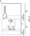
- FIG. 21 is an example illustration 2100 of a first subframe 2110 and a second subframe 2112 according to a possible embodiment.
- the first subframe can include a control region 2121, low latency data 2240, and a regular latency data region 2250.
- the second subframe 2112 can include a control region 2122 including a marker 2130.
- a marker transmission 2130 in one subframe 2112 (e.g. subframe n+1) may indicate the REs/LCEs/DCEs/CCEs/RBs/RBGs used for low latency transmission in OFDM symbols of another subframe 2121 (e.g. subframe n).
- the marker transmission 2130 in subframe n+1 2112 can be sent in the first few OFDM symbols (e.g.
- control channels such as PDCCH or PHICH, that are typically used in the control region.
- PDCCH Physical Downlink Control Channel
- PHICH Physical Downlink Control Channel
- the marker transmission can be differentiated from other control channel transmissions by using a special CRC mask (e.g. marker-RNTI) for the marker transmissions.
- CRC mask e.g. marker-RNTI
- PHICH PHICH is used for marker transmission, one or more of the PHICH groups can be preconfigured or predefined to be used for marker transmissions.
- FIG. 20 is an example illustration of a subframe 2000 according to another possible implementation.
- the subframe 2000 can include a control region 2010, a data region 2020, a marker 2030, low latency data resource elements 2040, and a regular latency data region 2050.
- the marker transmission 2030 can be sent by puncturing the RBs assigned for regular latency transmission 2050.
- a set of PDSCH RBs can be assigned to a user in a subframe. Some REs within an OFDM symbol (e.g. the last OFDM symbol) of one or more of those RBs can be used for marker transmission. If multiple users are assigned PDSCH RBs in the same subframe, then a separate marker transmission for each user can be sent within the assigned RBs of each user.
- the marker transmission can be sent by puncturing the user's PDSCH allocation.
- the puncturing can be similar to a LTE mechanism where ACK/NACK and Rank Indicator (RI) bits are transmitted by puncturing the PUSCH allocation.
- the marker may be transmitted using a predefined mapping within the user's assigned RBs, such as on the last symbol and on the higher end of the RB indices of the user allocation.
- the information payload of marker transmission can be used for identifying symbols, and other bits for identifying Resource Block Groups (RBG's) punctured within the user's, such as the device's, allocation.
- RBG's Resource Block Groups
- This can be optimized by grouping allocated RBG's and identifying only the top, middle, or other groupings within the user's allocation as being punctured.
- FIG. 22 is an example illustration of a subframe 2200 according to a possible embodiment.
- the subframe 2200 can include a control region 2210, a data region 2220, a marker 2230, low latency data 2240 and a regular latency data region 2250.
- the device can then determine that a marker signal can be present in RB0-RB2 in OFDM symbols 4 and 5 of the first slot and OFDM symbols 0, 1, 4, and 5 of the second slot in time domain of the subframe.
- the possible locations of a marker signal can be a predefined set of RBs (e.g. RB0-RB2) in every OFDM symbol configured for LL transmission.
- Code Block (CB) segmentation can be used to segment a large transport block in to smaller pieces and these small pieces are individually CRC-encoded, turbo coded, rate-matched, scrambled, and mapped to modulation symbols.
- CB Code Block
- a single modulation symbol or RE may not contain bits from different code blocks.
- the code blocks for a given Transport Block (TB) can be mapped in a frequency-first mapping as shown in the TB 600.
- the TB 600 can assume a transport block segmented into four code blocks occupying the subframe.
- CRS channel estimation can be performed and then LLR's for CB0 can be generated to kick-start a turbo decoding process. It is possible to start early decoding by relying only on CRS in symbol 0. Typically, all the CRS RE's in a given subframe can be used for PDSCH demodulation. Also, cross-subframe channel estimation for CRS is not assumed here. For DMRS based channel estimation, a device may have to wait until at least symbol 7 for performing DMRS based channel estimation. Typically, DMRS from both slots can be used for improving channel estimation.
- a device configured with Low-Latency transmission mode can transmit HARQ ACK in n+2 instead of n+4, can have a TB size restriction, can have a TA restriction that can limit the configuration of the smaller latency to small(er) cells, and can have dedicated PDSCH resource like in SPS.
- the ACK/NACK feedback can be similar to Rel-8, such as dynamic ACK/NACK based on control channel CCE index or as in SPS.
- the device can be configured via higher layers with a low-latency transmission mode or a low-latency feature. In such a case, the device may be required to transmit the HARQ feedback faster than a Rel-8 device.
- a higher layer configuration message can be received.
- the higher layer configuration message can indicate a set of resource blocks for receiving data packets in at least one symbol of a subframe.
- the at least one symbol can be outside of a control region of a subframe.
- the higher layer configuration message can also indicate a set of candidate symbols in the subframe, the at least one symbol belonging to the set of candidate symbols, the set of candidate symbols being less than all of the symbols in the subframe.
- the higher layer configuration message can further indicate a location of the at least one symbol of the subframe.
- An attempt can be made to decode control information in the subframe, such as in a control region of the subframe.
- the control information can assign resources for receiving a normal latency data packet, where the normal latency data packet can have a longer latency that the low latency data packet.
- an ACK/NACK can be transmitted in a third subframe with a second offset to the first subframe, where the second offset is greater than the first offset.
- a data payload of the decoded data packet can be delivered to an application layer.
- the flowchart 1300 can end.
- a feedback packet can be transmitted in a following subframe n+4 when the received packet is based on the regular latency configuration.
- the following subframe n+4 can be the fourth subframe from the subframe n.
- FIG. 15 is an example flowchart 1500 illustrating the operation of a wireless communication device, such as the device 120, according to a possible embodiment.
- the method can be performed in a base station, such as an eNB, and/or can also be performed in any other device, such as a UE in a peer-to-peer network, an access point, or any other device that can transmit data.
- the flowchart 1500 describes, among other things, different features for signaling the existence and/or location of low latency data transmissions. Thus, all of the features are not necessary, as some may be redundant.
- the flowchart 1500 can begin.
- a second set of time-frequency resources in the subframe can be determined.
- the second set of time-frequency resources can be used for a low latency data transmission and can overlap with at least a portion of the first set of time-frequency resources.
- the second set of time-frequency resources can be determined based on the received marker signal.
- the second set of time-frequency resources can include at least a set of OFDM symbols in the subframe and the marker signal can be received in all OFDM symbols of the set of OFDM symbols.
- the marker signal received at 1635 can also indicate a third set of time-frequency resources.
- the third set of time-frequency can include at least the time-frequency resources within the at least one OFDM symbol where low latency data is received.
- the apparatus 1700 and/or the controller 1720 may implement any operating system, such as Microsoft Windows®, UNIX®, or LINUX®, AndroidTM, or any other operating system.
- Apparatus operation software may be written in any programming language, such as C, C++, Java or Visual Basic, for example.
- Apparatus software may also run on an application framework, such as, for example, a Java® framework, a .NET® framework, or any other application framework.
- the software and/or the operating system may be stored in the memory 1770 or elsewhere on the apparatus 1700.
- the apparatus 1700 and/or the controller 1720 may also use hardware to implement disclosed operations.
- the controller 1720 may be any programmable processor.
- the transceiver 1750 can receive a higher layer configuration message, where the higher layer can be higher than a physical layer.
- the controller 1720 can determine, based on the higher layer configuration message, a first region of a subframe for receiving data packets.
- the data packets in the first region can be low latency data packets that have a lower maximum latency than normal latency data packets in a second region.
- the data packet comprises a low latency data packet with a latency lower than a normal data packet.
- the first region can be used for transmitting control signals for decoding normal latency data packets in the second region.
- the first region can be a first chronological region of a subframe, where the first region can include up to four multicarrier symbols.
- the first region can be a control region including at least one physical downlink control channel including control channel elements.
- the data packets can be received on one or more of the control channel elements including resource elements from the first set of resource elements.
- the first identifier can be a Cell Radio Network Temporary Identifier (C-RNTI) received in the higher layer configuration message and the second identifier can be a Low Latency Radio Network Temporary Identifier (low latency-RNTI) received in the higher layer configuration message.
- C-RNTI Cell Radio Network Temporary Identifier
- low latency-RNTI Low Latency Radio Network Temporary Identifier
- the controller 1720 can attempt to decode a data packet in a first set of resource elements (LCE0) within the set of resource blocks, the first set of resource elements in the at least one symbol of the subframe.
- the first set of resource elements can be a subset of resource elements used for control channel monitoring in a subframe.
- the control channel can assign resources in a second region of the subframe for data.
- the controller 1720 can successfully decode the data packet in one of the first set of resource elements and the second set of resource elements.
- the subframe can be a first subframe and the transceiver 1750 can transmit an ACK, in response to decoding the first packet, in a time-frequency resource in a second subframe with a first offset to the first subframe, in response to successfully decoding the data packet.
- the higher layer configuration message can indicate a set of resource blocks for receiving low latency data packets in at least one symbol of a subframe, where the higher layer can be higher than a physical layer.
- the data packet can be a low latency data packet and the controller 1750 can attempt to decode control information in the subframe.
- the control information can assign resources for receiving a normal latency data packet, where the normal latency data packet has a longer latency that the low latency data packet.
- the controller 1750 can decode the normal latency data packet and the transceiver can then transmit an ACK/NACK in a third subframe with a second offset to the first subframe in response to decoding the normal latency data packet where the second offset is greater than the first offset.
- the controller 1720 can deliver a data payload of the decoded data packet to an application layer.
- the transceiver 1750 can receive a higher layer configuration.
- the higher layer configuration can be higher than a physical layer configuration.
- the higher layer configuration indicating can configured the apparatus 1700 with a low latency configuration for a low latency transmission mode in addition to a regular latency configuration for a regular latency transmission mode.
- the low latency transmission mode can have a shorter latency than the regular latency transmission mode.
- the transceiver 1750 can receive a packet based on one of the low latency configuration and the regular latency transmission mode in subframe n.
- a code block size in a subframe for packets based on the low latency configuration can be smaller than a code block size for packets based on the regular latency configuration.
- a maximum timing advance value for the low latency configuration can be less than a maximum timing advance value for the regular latency configuration.
- the controller 1720 can identify the packet as being based on the low latency configuration based on the packet being received on a given transport bearer.
- the controller 1720 can identify the packet as being on the low latency configuration based on the packet being received from a certain cell.
- the controller 17220 can also identify the packet as being based on the low latency configuration based on other characteristics of the packet and/or surrounding transmissions.
- a transport block of the low latency configuration can be smaller than a transport block for the regular latency configuration.
- the packet based on the low latency configuration can be received on a dedicated resource on a Physical Downlink Shared Channel (PDSCH).
- PDSCH Physical Downlink Shared Channel
- the transceiver 1750 can transmit a feedback packet in a following subframe n+p, where p ⁇ 4 when the received packet is based on the low latency configuration.
- the following subframe n+p can be the p th subframe from the subframe n.
- the feedback packet can be a hybrid automatic repeat request acknowledgement sent in the following subframe that is two subframes n+2 after the first subframe n in response to receiving the packet based on the low latency configuration in the first subframe n.
- the hybrid automatic repeat request acknowledgement can be transmitted in a temporal portion of the subframe including at least two symbols with resource elements assigned to the device for uplink feedback transmission.
- the transceiver 1750 can transmit a feedback packet in a following subframe n+4 when the received packet is based on the regular latency configuration, where the following subframe n+4 can be the fourth subframe from the subframe n.
- the transceiver 1750 can receive a resource assignment.
- the controller 1720 can determine a first set of time-frequency resources in a subframe from the resource assignment.
- the controller 1720 can determine a second set of time-frequency resources in the subframe.
- the second set of time-frequency resources can be used for a low latency data transmission.
- the second set of time-frequency resources can overlap with at least a portion of the first set of time-frequency resources.
- the transceiver 1750 can receive a regular latency data transmission in the subframe.
- the controller 1720 can decode the regular latency data transmission in the subframe based on the determined first and second set of time-frequency resources, where the regular latency transmission can have a longer latency than the low latency transmission.
- the transceiver 1750 can monitor a first control channel in a first temporal portion of a subframe.
- the combination of the transceiver 1750 and the controller 1720 can also be considered to monitor control channels in a subframe in that the transceiver 1750 can receive the subframe and the controller 1720 can attempt to decode the control channels.
- the subframe can include a plurality of OFDM symbols in a time domain and a plurality of subcarriers in a frequency domain.
- the first control channel can occupy a first portion of subcarriers less than the plurality of subcarriers.
- the first control channel can assign data resources only in the first temporal portion of the subframe.
- the transceiver can monitor a second control channel in a second temporal portion of a subframe.
- the first temporal portion can occupy at least one different OFDM symbol in the subframe from the second temporal portion.
- the second temporal portion can also occupy at least one different OFDM symbol in the subframe from the first temporal portion.
- the second control channel can occupy a second portion of subcarriers that are less than the plurality of subcarriers.
- the second control channel can assign data resources only in the second temporal portion of the subframe.
- the controller 1720 can decode the first control channel.
- the transceiver 1750 in response to decoding the first control channel, can receive data in the first temporal portion of the subframe.
- the data in the first temporal portion can be assigned by the first control channel.
- the controller 1720 can decode the data.
- the transceiver 1840 can create a data connection with the device 110.
- the controller 1810 can be any programmable processor. Disclosed embodiments can also be implemented on a general-purpose or a special purpose computer, a programmed microprocessor or microprocessor, peripheral integrated circuit elements, an application-specific integrated circuit or other integrated circuits, hardware/electronic logic circuits, such as a discrete element circuit, a programmable logic device, such as a programmable logic array, field programmable gate-array, or the like.
- the controller 1810 can be any controller or processor device or devices capable of operating a device and implementing the disclosed embodiments.
- the memory 1820 can include volatile and nonvolatile data storage, including one or more electrical, magnetic, or optical memories, such as a Random Access Memory (RAM), cache, hard drive, or other memory device.
- RAM Random Access Memory
- the memory 1820 can have a cache to speed access to specific data.
- the memory 1820 can also be connected to a Compact Disc - Read Only Memory (CD-ROM), Digital Video Disc - Read Only memory (DVD-ROM), DVD read write input, tape drive, thumb drive, or other removable memory device that allows media content to be directly uploaded into a system.
- Data can be stored in the memory 1820 or in a separate database.
- the database interface 1830 can be used by the controller 1810 to access the database.
- the I/O device interface 1850 can be connected to one or more input and output devices that may include a keyboard, a mouse, a touch screen, a monitor, a microphone, a voice-recognition device, a speaker, a printer, a disk drive, or any other device or combination of devices that accept input and/or provide output.
- the network connection interface 1860 can be connected to a communication device, modem, network interface card, a transceiver, or any other device capable of transmitting and receiving signals to and from a network.
- the components of the device 1800 can be connected via the bus 1870, may be linked wirelessly, or may be otherwise connected.
- the elements any of the device 1800 can perform the device and apparatus methods and processes described in the disclosed embodiments.
- the device 1800 and/or the controller 1810 can generate the signals and the transceiver 1840 can transmit the signals that are received by the device 110.
- the controller 1810 can configure a first control channel and a second control channel.
- the transceiver 1840 can transmit the first control channel in a first temporal portion of a subframe.
- the subframe can include a plurality of OFDM symbols in a time domain and a plurality of subcarriers in a frequency domain.
- the first control channel can occupy a first portion of subcarriers that are less than the plurality of subcarriers.
- the first control channel can assign first data resources only in the first temporal portion of the subframe.
- the transceiver 1840 can transmit the second control channel in a second temporal portion of a subframe.
- the second control channel can occupy a second portion of subcarriers that is less than the plurality of subcarriers.
- the controller 1810 can also configure a third control channel.
- the transceiver 1840 can transmit the third control channel.
- the third control channel can occupy at least a third OFDM symbol in a third temporal portion in the subframe different from first temporal portion and the second temporal portion.
- the third control channel can assign third data resources in a fourth temporal portion different from the third temporal portion.
- a third control channel can be transmitted.
- the third control channel can occupy at least a third OFDM symbol in a third temporal portion in the subframe, such as the Legacy Control portion of the TTI 500 described above, different from first temporal portion and the second temporal portion, the third control channel assigning third data resources in a fourth temporal portion, such as the Legacy Allocation portion of the TTI 500 described above, different from the third temporal portion.
- the fourth temporal portion can include the first temporal portion and the second temporal portion.
- the subframe can include a beginning OFDM symbol and the third temporal portion can include the beginning OFDM symbol in the subframe.
- data can be transmitted in the first data resources in the first temporal portion.
- the first temporal portion can overlap the fourth temporal portion.
- the data can correspond to the first control channel.
- low latency data packet can be transmitted in the first data resources in the first temporal portion and the low latency data packet can have a shorter latency than a normal latency data packet transmitted in the third data resources in the fourth temporal portion.
- the flowchart 2300 can end.
- the second control channel can also occupy a second portion of subcarriers less than the plurality of subcarriers.
- the first portion of subcarriers and the second portion of subcarriers can be configured by higher layers than a physical layer.
- the second control channel can assign data resources only in the second temporal portion of the subframe.
- the first control channel can be decoded.
- data can be received in the first temporal portion of the subframe.
- the data in the first temporal portion can be assigned by the first control channel.
- the data in the first temporal portion of the subframe can be on different subcarriers from the first control channel. For example, data can be received in the first data resources in the first temporal portion, where the first temporal portion can overlap the fourth temporal portion, and where the data can correspond to the first control channel.
Landscapes
- Engineering & Computer Science (AREA)
- Signal Processing (AREA)
- Computer Networks & Wireless Communication (AREA)
- Environmental & Geological Engineering (AREA)
- Computer Security & Cryptography (AREA)
- Mobile Radio Communication Systems (AREA)
Applications Claiming Priority (4)
| Application Number | Priority Date | Filing Date | Title |
|---|---|---|---|
| US201562252092P | 2015-11-06 | 2015-11-06 | |
| US15/013,014 US10075949B2 (en) | 2016-02-02 | 2016-02-02 | Method and apparatus for low latency transmissions |
| PCT/US2016/059850 WO2017079127A1 (fr) | 2015-11-06 | 2016-11-01 | Procédé et appareil pour des transmissions à faible latence |
| EP16801899.2A EP3342086B1 (fr) | 2015-11-06 | 2016-11-01 | Procédé et appareil pour des transmissions à faible latence |
Related Parent Applications (2)
| Application Number | Title | Priority Date | Filing Date |
|---|---|---|---|
| EP16801899.2A Division EP3342086B1 (fr) | 2015-11-06 | 2016-11-01 | Procédé et appareil pour des transmissions à faible latence |
| EP16801899.2A Division-Into EP3342086B1 (fr) | 2015-11-06 | 2016-11-01 | Procédé et appareil pour des transmissions à faible latence |
Publications (2)
| Publication Number | Publication Date |
|---|---|
| EP3883171A1 true EP3883171A1 (fr) | 2021-09-22 |
| EP3883171B1 EP3883171B1 (fr) | 2024-09-18 |
Family
ID=58664134
Family Applications (5)
| Application Number | Title | Priority Date | Filing Date |
|---|---|---|---|
| EP16788934.4A Active EP3342083B1 (fr) | 2015-11-06 | 2016-10-25 | Procédé et appareil pour transmissions à faible latence |
| EP16794826.4A Active EP3342078B1 (fr) | 2015-11-06 | 2016-10-26 | Procédé et appareil pour des transmissions à faible latence |
| EP16801899.2A Active EP3342086B1 (fr) | 2015-11-06 | 2016-11-01 | Procédé et appareil pour des transmissions à faible latence |
| EP16794879.3A Active EP3342085B1 (fr) | 2015-11-06 | 2016-11-01 | Procédé et appareil pour des transmissions à faible latence |
| EP21172654.2A Active EP3883171B1 (fr) | 2015-11-06 | 2016-11-01 | Procédé et appareil de transmissions à faible latence |
Family Applications Before (4)
| Application Number | Title | Priority Date | Filing Date |
|---|---|---|---|
| EP16788934.4A Active EP3342083B1 (fr) | 2015-11-06 | 2016-10-25 | Procédé et appareil pour transmissions à faible latence |
| EP16794826.4A Active EP3342078B1 (fr) | 2015-11-06 | 2016-10-26 | Procédé et appareil pour des transmissions à faible latence |
| EP16801899.2A Active EP3342086B1 (fr) | 2015-11-06 | 2016-11-01 | Procédé et appareil pour des transmissions à faible latence |
| EP16794879.3A Active EP3342085B1 (fr) | 2015-11-06 | 2016-11-01 | Procédé et appareil pour des transmissions à faible latence |
Country Status (5)
| Country | Link |
|---|---|
| US (5) | US11589347B2 (fr) |
| EP (5) | EP3342083B1 (fr) |
| KR (3) | KR102185753B1 (fr) |
| CN (3) | CN108352962B (fr) |
| WO (4) | WO2017078966A1 (fr) |
Families Citing this family (41)
| Publication number | Priority date | Publication date | Assignee | Title |
|---|---|---|---|---|
| BR112013030743B1 (pt) * | 2011-08-12 | 2022-05-17 | Sun Patent Trust | Aparelho terminal, método de comunicação, aparelho de estação base e circuito integrado para controlar um processo |
| US10104683B2 (en) * | 2015-02-06 | 2018-10-16 | Qualcomm Incorporated | Parallel low latency awareness |
| EP3370468B1 (fr) * | 2015-06-11 | 2023-02-22 | Apple Inc. | Accès multiple par répartition de code superposé amélioré (cdma) |
| WO2017096558A1 (fr) * | 2015-12-09 | 2017-06-15 | Qualcomm Incorporated | Mappage de ressources et détermination de mcs flexibles |
| US11452091B2 (en) * | 2016-02-04 | 2022-09-20 | Acer Incorporated | Device and method of handling hybrid automatic repeat request transmission |
| JP6707892B2 (ja) * | 2016-02-22 | 2020-06-10 | ソニー株式会社 | 基地局装置及び基地局装置の制御方法 |
| CN116865925A (zh) * | 2016-03-30 | 2023-10-10 | 交互数字专利控股公司 | 用于下行链路物理信道以减少lte高级系统中延迟的方法 |
| CN108702259B (zh) * | 2016-04-01 | 2022-03-18 | 诺基亚通信公司 | 用于无线网络的低时延混合自动重传请求(harq)反馈 |
| WO2017177083A1 (fr) | 2016-04-08 | 2017-10-12 | Idac Holdings, Inc. | Multiplexage de couche phy de différents types de trafic dans des systèmes 5g |
| WO2018014162A1 (fr) * | 2016-07-18 | 2018-01-25 | 广东欧珀移动通信有限公司 | Procédé et dispositif de transmission de données |
| CN107733615B (zh) * | 2016-08-12 | 2022-09-09 | 中兴通讯股份有限公司 | 信令消息的发送、检测装置、传输系统 |
| WO2018043960A1 (fr) * | 2016-09-01 | 2018-03-08 | 주식회사 케이티 | Procédé et dispositif de transmission et de réception de données dans un réseau sans fil de prochaine génération |
| RU2716500C1 (ru) * | 2016-09-30 | 2020-03-12 | Телефонактиеболагет Лм Эрикссон (Пабл) | Способ расстановки приоритетов мощности восходящей линии для коротких интервалов времени передачи |
| CN110073619B (zh) * | 2016-11-02 | 2022-06-03 | Idac控股公司 | 共享数据信道设计 |
| US11304190B2 (en) * | 2016-11-08 | 2022-04-12 | Qualcomm Incorporated | Search space design and use |
| WO2018101880A1 (fr) * | 2016-11-30 | 2018-06-07 | Telefonaktiebolaget Lm Ericsson (Publ) | Procédé de gestion d'utilisateurs ayant des exigences d'alignement temporel différentes |
| KR20180068677A (ko) * | 2016-12-14 | 2018-06-22 | 삼성전자주식회사 | 무선 통신 시스템에서 하향링크 제어채널의 송수신 방법 및 장치 |
| KR102355817B1 (ko) * | 2017-01-17 | 2022-01-26 | 삼성전자 주식회사 | 이동 통신 시스템에서의 반영속적 채널 상태 보고 방법 및 장치 |
| US10028210B1 (en) * | 2017-03-23 | 2018-07-17 | At&T Intellectual Property I, L.P. | Encoding and decoding data for group common control channels |
| CN108933641B (zh) | 2017-05-22 | 2022-10-11 | 中兴通讯股份有限公司 | 数据发送、处理方法及装置,网络侧设备和终端 |
| EP4075712A1 (fr) * | 2017-06-13 | 2022-10-19 | Motorola Mobility LLC | Procédé et appareil destinés à une structure physique de commande de liaison descendante dans un fonctionnement à latence réduite |
| US20180367262A1 (en) * | 2017-06-14 | 2018-12-20 | Mediatek Inc. | Techniques of transmitting harq-ack feedback by user equipment |
| US11038646B2 (en) * | 2017-06-26 | 2021-06-15 | Qualcomm Incorporated | Techniques and apparatuses for shared reference signal transmission and reception |
| WO2019006582A1 (fr) * | 2017-07-03 | 2019-01-10 | Qualcomm Incorporated | Système et procédé de réduction de latence à trafic sensible au retard |
| US11012922B2 (en) * | 2017-09-18 | 2021-05-18 | Qualcomm Incorporated | Common search space design for coverage enhancement in wireless communications |
| US10736112B2 (en) * | 2017-10-19 | 2020-08-04 | Qualcomm Incorporated | Common search space scrambling for MulteFire coverage enhancement |
| CN111373685A (zh) | 2017-11-17 | 2020-07-03 | 瑞典爱立信有限公司 | 通过使用已知的打孔信息来改进解码 |
| CN109802772B (zh) * | 2017-11-17 | 2020-12-08 | 华为技术有限公司 | 一种信息发送的方法及设备 |
| DK3556042T3 (da) * | 2017-11-17 | 2020-04-27 | Ericsson Telefon Ab L M | Udvalg af allokeringstabeller til tidsdomæneressourcer |
| CN111466091B (zh) | 2017-12-13 | 2023-08-18 | 高通股份有限公司 | 用于控制信道的软组合 |
| US11705982B2 (en) * | 2018-01-23 | 2023-07-18 | Qualcomm Incorporated | Methods and apparatus for adjusting wireless communication structure |
| US10673553B2 (en) * | 2018-03-23 | 2020-06-02 | Qualcomm Incorporated | Search space overbooking and pruning |
| US11089582B2 (en) * | 2018-04-05 | 2021-08-10 | Huawei Technologies Co., Ltd. | Method and system for downlink control information payload size determination |
| WO2019203884A1 (fr) * | 2018-04-18 | 2019-10-24 | Battelle Energy Alliance, Llc | Systèmes, dispositifs, et procédés pour une communication de données avec des véhicules aériens sans pilote via un canal de diffusion sous-jacent |
| CN110830156B (zh) * | 2018-08-09 | 2021-11-26 | 大唐移动通信设备有限公司 | 一种信道传输方法、装置、终端及基站 |
| CN111148238B (zh) * | 2018-11-03 | 2023-03-17 | 上海朗帛通信技术有限公司 | 一种被用于无线通信的节点中的方法和装置 |
| US11533715B2 (en) | 2019-02-08 | 2022-12-20 | Qualcomm Incorporated | Reliable low latency wireless communications |
| CN112219366A (zh) * | 2019-05-09 | 2021-01-12 | Oppo广东移动通信有限公司 | 资源配置方法、装置、计算机设备和存储介质 |
| US20220216965A1 (en) * | 2019-08-15 | 2022-07-07 | Nec Corporation | Transmission and reception of downlink control information |
| WO2021206594A1 (fr) * | 2020-04-07 | 2021-10-14 | Telefonaktiebolaget Lm Ericsson (Publ) | Informations de commande sur un canal de données |
| US11736972B2 (en) * | 2021-03-31 | 2023-08-22 | Qualcomm Incorporated | Protocol overhead reduction |
Citations (2)
| Publication number | Priority date | Publication date | Assignee | Title |
|---|---|---|---|---|
| US20150180622A1 (en) * | 2013-12-23 | 2015-06-25 | Qualcomm Incorporated | Mixed numerology ofdm design |
| US20150280871A1 (en) * | 2014-03-28 | 2015-10-01 | Qualcomm Incorporated | Ultra low latency design for lte |
Family Cites Families (58)
| Publication number | Priority date | Publication date | Assignee | Title |
|---|---|---|---|---|
| US20080220775A1 (en) | 1997-07-30 | 2008-09-11 | Steven Tischer | Apparatus, method, and computer-readable medium for securely providing communications between devices and networks |
| FR2838281B1 (fr) * | 2002-04-04 | 2004-07-09 | Evolium Sas | Procede pour le controle de droits d'acces dans un systeme cellulaire de radiocommunications mobiles |
| US7295632B2 (en) | 2003-03-20 | 2007-11-13 | Texas Instruments Incorporated | Method and apparatus for decoding punctured subframes |
| EP1834449B1 (fr) * | 2004-12-29 | 2012-04-18 | Telefonaktiebolaget LM Ericsson (publ) | Porteurs prioritaires dans un reseau de telecommunication mobile |
| GB0600814D0 (en) * | 2006-01-17 | 2006-02-22 | Siemens Ag | A Method Of Resource Allocation In A Communication System |
| US9094257B2 (en) * | 2006-06-30 | 2015-07-28 | Centurylink Intellectual Property Llc | System and method for selecting a content delivery network |
| CN104780027B (zh) | 2006-10-27 | 2018-09-04 | 三菱电机株式会社 | 数据通信方法、通信系统及移动终端 |
| US7873010B2 (en) | 2007-03-07 | 2011-01-18 | Motorola Mobility, Inc. | Control signaling resource assignment in wireless communication networks |
| US9344259B2 (en) | 2007-06-20 | 2016-05-17 | Google Technology Holdings LLC | Control channel provisioning and signaling |
| CN101400112B (zh) * | 2007-09-24 | 2012-05-09 | 中兴通讯股份有限公司 | Td-scdma系统中寻呼状态的数据传输方法 |
| US8326292B2 (en) * | 2008-06-03 | 2012-12-04 | Innovative Sonic Limited | Method and apparatus for determining dedicate searching space in physical downlink control channel |
| CN101631007B (zh) * | 2008-07-14 | 2013-06-05 | 电信科学技术研究院 | 一种数据传输方法、装置和系统 |
| EP2166804A1 (fr) | 2008-09-17 | 2010-03-24 | Panasonic Corporation | Désactivation d'affectations de ressources semi-constantes dans un réseau de communication mobile |
| US20100120442A1 (en) * | 2008-11-12 | 2010-05-13 | Motorola, Inc. | Resource sharing in relay operations within wireless communication systems |
| CN101784076B (zh) * | 2009-01-21 | 2012-11-21 | 电信科学技术研究院 | 降低多载波系统中harq重传时间间隔的方法和基站 |
| US7940740B2 (en) | 2009-02-03 | 2011-05-10 | Motorola Mobility, Inc. | Apparatus and method for communicating and processing a positioning reference signal based on identifier associated with a base station |
| JP5384720B2 (ja) * | 2009-04-03 | 2014-01-08 | テレフオンアクチーボラゲット エル エム エリクソン(パブル) | ユーザ装置における上りリンクのリンクアダプテーション |
| US9634806B2 (en) * | 2009-06-11 | 2017-04-25 | Qualcomm Incorporated | Data prioritization for a power-limited UE in a wireless communication system |
| US8194603B2 (en) | 2009-08-18 | 2012-06-05 | Motorola Mobility, Inc. | Subframe component reduction and notification in a heterogeneous wireless communication system |
| US20120230216A1 (en) * | 2009-10-29 | 2012-09-13 | Electronics And Telecommunications Research Institute | Communication method |
| BR112012012632B1 (pt) | 2009-11-27 | 2020-12-15 | Qualcomm Incorporated | Método e equipamento para aumentar a capacidade de transmissão em comunicações sem fio, e memória legível por computador |
| GB2484101A (en) | 2010-09-29 | 2012-04-04 | Nec Corp | Adjusting a load threshold for use in call admission control at a node based on blocking and outage rates |
| GB2487782B (en) | 2011-02-04 | 2015-05-20 | Sca Ipla Holdings Inc | Telecommunications method and system |
| US8630253B2 (en) | 2011-05-02 | 2014-01-14 | Futurewei Technologies, Inc. | System and method for mapping data symbols |
| US9197387B2 (en) | 2011-08-15 | 2015-11-24 | Google Technology Holdings LLC | Method and apparatus for control channel transmission and reception |
| EP2759085A1 (fr) | 2011-09-21 | 2014-07-30 | Nokia Solutions and Networks Oy | Appareil et procédé de communication |
| US9113463B2 (en) | 2011-11-04 | 2015-08-18 | Qualcomm Incorporated | Resource management for enhanced PDCCH |
| EP2590350A1 (fr) | 2011-11-07 | 2013-05-08 | Panasonic Corporation | Chevauchement PDCCH amélioré dans la région PDCCH |
| WO2013098594A1 (fr) * | 2011-12-30 | 2013-07-04 | Nokia Corporation | Procédé et appareil d'extension de couverture |
| WO2014042456A1 (fr) * | 2012-09-17 | 2014-03-20 | 엘지전자 주식회사 | Procédé et appareil de réception de signal de liaison descendante dans un système de communication sans fil |
| US10477557B2 (en) | 2012-12-03 | 2019-11-12 | Sony Corporation | Transmission of control information to reduced bandwidth terminals |
| WO2014098701A1 (fr) | 2012-12-21 | 2014-06-26 | Telefonaktiebolaget L M Ericsson (Publ) | Annulation de messages d'ordonnancement multi-tti |
| US8867425B2 (en) * | 2012-12-21 | 2014-10-21 | Motorola Solutions, Inc. | Method and apparatus multimedia broadcast/multicast service coverage boost |
| CN103001752B (zh) * | 2012-12-24 | 2015-06-03 | 新邮通信设备有限公司 | 一种基于过渡无线帧的动态tdd混合重传方案 |
| CN104919772B (zh) | 2013-01-11 | 2018-10-12 | 交互数字专利控股公司 | 用于适应性调制的系统和方法 |
| EP2938145B1 (fr) | 2013-01-18 | 2017-03-15 | Huawei Technologies Co., Ltd. | Procédé et dispositif permettant de déterminer un candidat epdcch |
| US9083492B2 (en) * | 2013-02-15 | 2015-07-14 | Cortina Systems, Inc. | Apparatus and method for communicating data over a communication channel |
| US20140328260A1 (en) | 2013-02-26 | 2014-11-06 | Samsung Electronics Co., Ltd. | Scheduling over multiple transmission time intervals |
| US9444745B2 (en) * | 2013-03-08 | 2016-09-13 | Blackberry Limited | Sending data rate information to a wireless access network node |
| US10263734B2 (en) | 2013-11-12 | 2019-04-16 | Telefonaktiebolaget Lm Ericsson (Publ) | Devices and methods for handling blind (re) transmissions in a network |
| US11432305B2 (en) | 2014-05-19 | 2022-08-30 | Qualcomm Incorporated | Apparatus and method for synchronous multiplexing and multiple access for different latency targets utilizing thin control |
| US20150349929A1 (en) | 2014-06-02 | 2015-12-03 | Abhijeet Bhorkar | Evolved node-b, user equipment, and methods for hybrid automatic repeat request (harq) communication |
| US9775151B2 (en) | 2014-07-21 | 2017-09-26 | Intel IP Corporation | System and method for TDD communications |
| US20160030891A1 (en) | 2014-07-31 | 2016-02-04 | Clark Technology, LLC | Single-stage water treatment system |
| WO2016022841A1 (fr) | 2014-08-08 | 2016-02-11 | Kyocera Corporation | Gestion de canal de dispositif à dispositif (d2d) avec transmission de signal de référence assistée par réseau |
| US10680771B2 (en) | 2014-08-28 | 2020-06-09 | Qualcomm Incorporated | Reference signal transmission and averaging for wireless communications |
| US10880883B2 (en) * | 2014-09-02 | 2020-12-29 | Qualcomm Incorporated | Low-latency, low-bandwidth and low duty cycle operation in a wireless communication system |
| US10064165B2 (en) | 2014-10-03 | 2018-08-28 | Qualcomm Incorporated | Downlink and uplink channel with low latency |
| US10594652B2 (en) | 2014-10-16 | 2020-03-17 | Qualcomm Incorporated | Wireless communication utilizing a unified air interface |
| US10764012B2 (en) | 2014-11-06 | 2020-09-01 | Qualcomm Incorporated | Reducing processing time for low latency transmission and reception |
| US20160143030A1 (en) * | 2014-11-14 | 2016-05-19 | Electronics And Telecommunications Research Institute | Method of transmitting frame for supporting legacy system, and method and apparatus of searching cell using the same |
| US10939454B2 (en) | 2014-12-11 | 2021-03-02 | Qualcomm Incorporated | Prioritizing colliding transmissions in LTE and ultra-low latency LTE communications |
| US10484135B2 (en) | 2014-12-15 | 2019-11-19 | Qualcomm Incorporated | Mitigation of bursty interference |
| EP3328151B1 (fr) * | 2015-01-26 | 2023-10-18 | ASUS Technology Licensing Inc. | Procédé et appareil de détection de faisceau dans un système de communication sans fil |
| US10104683B2 (en) | 2015-02-06 | 2018-10-16 | Qualcomm Incorporated | Parallel low latency awareness |
| EP3269067B1 (fr) * | 2015-03-09 | 2019-08-07 | Telefonaktiebolaget LM Ericsson (publ) | Réduction de signaux de référence lors d'une communication de multiples sous-sous-trames entre une station de base et un terminal sans fil |
| US10743333B2 (en) | 2015-03-20 | 2020-08-11 | Lg Electronics Inc. | Method for dynamically allocating resources to frequency band of short TTI and device using same |
| US9814058B2 (en) * | 2015-05-15 | 2017-11-07 | Qualcomm Incorporated | Scaled symbols for a self-contained time division duplex (TDD) subframe structure |
-
2016
- 2016-02-02 US US15/012,997 patent/US11589347B2/en active Active
- 2016-02-02 US US15/012,969 patent/US10321455B2/en active Active
- 2016-02-02 US US15/012,982 patent/US11395292B2/en active Active
- 2016-10-25 KR KR1020187012534A patent/KR102185753B1/ko active IP Right Grant
- 2016-10-25 CN CN201680064580.8A patent/CN108352962B/zh active Active
- 2016-10-25 WO PCT/US2016/058592 patent/WO2017078966A1/fr active Application Filing
- 2016-10-25 EP EP16788934.4A patent/EP3342083B1/fr active Active
- 2016-10-26 CN CN201680064359.2A patent/CN108352945B/zh active Active
- 2016-10-26 KR KR1020187012533A patent/KR102165304B1/ko active IP Right Grant
- 2016-10-26 EP EP16794826.4A patent/EP3342078B1/fr active Active
- 2016-10-26 WO PCT/US2016/058836 patent/WO2017136008A1/fr active Application Filing
- 2016-11-01 EP EP16801899.2A patent/EP3342086B1/fr active Active
- 2016-11-01 WO PCT/US2016/059850 patent/WO2017079127A1/fr active Application Filing
- 2016-11-01 KR KR1020187012596A patent/KR102214855B1/ko active IP Right Grant
- 2016-11-01 CN CN201680064273.XA patent/CN108352959B/zh active Active
- 2016-11-01 EP EP16794879.3A patent/EP3342085B1/fr active Active
- 2016-11-01 WO PCT/US2016/059840 patent/WO2017079119A1/fr active Application Filing
- 2016-11-01 EP EP21172654.2A patent/EP3883171B1/fr active Active
-
2022
- 2022-06-24 US US17/848,990 patent/US20220322344A1/en active Pending
-
2023
- 2023-02-16 US US18/110,722 patent/US20230199733A1/en active Pending
Patent Citations (2)
| Publication number | Priority date | Publication date | Assignee | Title |
|---|---|---|---|---|
| US20150180622A1 (en) * | 2013-12-23 | 2015-06-25 | Qualcomm Incorporated | Mixed numerology ofdm design |
| US20150280871A1 (en) * | 2014-03-28 | 2015-10-01 | Qualcomm Incorporated | Ultra low latency design for lte |
Non-Patent Citations (1)
| Title |
|---|
| APPLE INC: "On the Structure and Usage Scenarios of ePDCCH", 3GPP DRAFT; R1-114300, 3RD GENERATION PARTNERSHIP PROJECT (3GPP), MOBILE COMPETENCE CENTRE ; 650, ROUTE DES LUCIOLES ; F-06921 SOPHIA-ANTIPOLIS CEDEX ; FRANCE, vol. RAN WG1, no. San Francisco, USA; 20111114 - 20111118, 9 November 2011 (2011-11-09), XP050562351 * |
Also Published As
Similar Documents
| Publication | Publication Date | Title |
|---|---|---|
| US20230199733A1 (en) | Method and Apparatus for Low Latency Transmissions | |
| US10051621B2 (en) | Method and apparatus for low latency transmissions | |
| US20230127448A1 (en) | Apparatus for low latency transmissions | |
| US10075949B2 (en) | Method and apparatus for low latency transmissions |
Legal Events
| Date | Code | Title | Description |
|---|---|---|---|
| PUAI | Public reference made under article 153(3) epc to a published international application that has entered the european phase |
Free format text: ORIGINAL CODE: 0009012 |
|
| STAA | Information on the status of an ep patent application or granted ep patent |
Free format text: STATUS: THE APPLICATION HAS BEEN PUBLISHED |
|
| AC | Divisional application: reference to earlier application |
Ref document number: 3342086 Country of ref document: EP Kind code of ref document: P |
|
| AK | Designated contracting states |
Kind code of ref document: A1 Designated state(s): AL AT BE BG CH CY CZ DE DK EE ES FI FR GB GR HR HU IE IS IT LI LT LU LV MC MK MT NL NO PL PT RO RS SE SI SK SM TR |
|
| STAA | Information on the status of an ep patent application or granted ep patent |
Free format text: STATUS: REQUEST FOR EXAMINATION WAS MADE |
|
| 17P | Request for examination filed |
Effective date: 20220322 |
|
| RBV | Designated contracting states (corrected) |
Designated state(s): AL AT BE BG CH CY CZ DE DK EE ES FI FR GB GR HR HU IE IS IT LI LT LU LV MC MK MT NL NO PL PT RO RS SE SI SK SM TR |
|
| GRAP | Despatch of communication of intention to grant a patent |
Free format text: ORIGINAL CODE: EPIDOSNIGR1 |
|
| STAA | Information on the status of an ep patent application or granted ep patent |
Free format text: STATUS: GRANT OF PATENT IS INTENDED |
|
| INTG | Intention to grant announced |
Effective date: 20240412 |
|
| GRAS | Grant fee paid |
Free format text: ORIGINAL CODE: EPIDOSNIGR3 |
|
| GRAA | (expected) grant |
Free format text: ORIGINAL CODE: 0009210 |
|
| STAA | Information on the status of an ep patent application or granted ep patent |
Free format text: STATUS: THE PATENT HAS BEEN GRANTED |
|
| AC | Divisional application: reference to earlier application |
Ref document number: 3342086 Country of ref document: EP Kind code of ref document: P |
|
| AK | Designated contracting states |
Kind code of ref document: B1 Designated state(s): AL AT BE BG CH CY CZ DE DK EE ES FI FR GB GR HR HU IE IS IT LI LT LU LV MC MK MT NL NO PL PT RO RS SE SI SK SM TR |
|
| REG | Reference to a national code |
Ref country code: GB Ref legal event code: FG4D |