EP3328151B1 - Procédé et appareil de détection de faisceau dans un système de communication sans fil - Google Patents
Procédé et appareil de détection de faisceau dans un système de communication sans fil Download PDFInfo
- Publication number
- EP3328151B1 EP3328151B1 EP18152087.5A EP18152087A EP3328151B1 EP 3328151 B1 EP3328151 B1 EP 3328151B1 EP 18152087 A EP18152087 A EP 18152087A EP 3328151 B1 EP3328151 B1 EP 3328151B1
- Authority
- EP
- European Patent Office
- Prior art keywords
- cell
- base station
- resources
- rss
- transmissions
- Prior art date
- Legal status (The legal status is an assumption and is not a legal conclusion. Google has not performed a legal analysis and makes no representation as to the accuracy of the status listed.)
- Active
Links
- 238000000034 method Methods 0.000 title claims description 79
- 238000004891 communication Methods 0.000 title claims description 40
- 238000001514 detection method Methods 0.000 title description 12
- 230000005540 biological transmission Effects 0.000 claims description 65
- 230000000737 periodic effect Effects 0.000 claims description 16
- 230000004044 response Effects 0.000 description 29
- 101000741965 Homo sapiens Inactive tyrosine-protein kinase PRAG1 Proteins 0.000 description 12
- 102100038659 Inactive tyrosine-protein kinase PRAG1 Human genes 0.000 description 12
- 238000010586 diagram Methods 0.000 description 11
- 230000009977 dual effect Effects 0.000 description 11
- 230000011664 signaling Effects 0.000 description 11
- 230000008569 process Effects 0.000 description 7
- 239000011159 matrix material Substances 0.000 description 6
- 238000012544 monitoring process Methods 0.000 description 6
- 230000002441 reversible effect Effects 0.000 description 6
- 241001229889 Metis Species 0.000 description 4
- 238000013461 design Methods 0.000 description 4
- 238000005516 engineering process Methods 0.000 description 4
- 238000010295 mobile communication Methods 0.000 description 4
- 238000012545 processing Methods 0.000 description 4
- 230000001143 conditioned effect Effects 0.000 description 3
- 230000007774 longterm Effects 0.000 description 3
- 230000008901 benefit Effects 0.000 description 2
- 238000004590 computer program Methods 0.000 description 2
- 230000006870 function Effects 0.000 description 2
- 230000003287 optical effect Effects 0.000 description 2
- 239000002245 particle Substances 0.000 description 2
- 230000008054 signal transmission Effects 0.000 description 2
- 238000001228 spectrum Methods 0.000 description 2
- 108700026140 MAC combination Proteins 0.000 description 1
- 238000013459 approach Methods 0.000 description 1
- 238000003491 array Methods 0.000 description 1
- 230000009286 beneficial effect Effects 0.000 description 1
- 230000001413 cellular effect Effects 0.000 description 1
- 230000000295 complement effect Effects 0.000 description 1
- 230000001934 delay Effects 0.000 description 1
- 230000003111 delayed effect Effects 0.000 description 1
- 230000001419 dependent effect Effects 0.000 description 1
- 230000001066 destructive effect Effects 0.000 description 1
- 238000001914 filtration Methods 0.000 description 1
- 230000006872 improvement Effects 0.000 description 1
- 230000000977 initiatory effect Effects 0.000 description 1
- 230000010354 integration Effects 0.000 description 1
- 230000008520 organization Effects 0.000 description 1
- 239000005022 packaging material Substances 0.000 description 1
- 230000009467 reduction Effects 0.000 description 1
- 230000001360 synchronised effect Effects 0.000 description 1
- 238000012546 transfer Methods 0.000 description 1
- 230000007704 transition Effects 0.000 description 1
Images


Classifications
-
- H—ELECTRICITY
- H04—ELECTRIC COMMUNICATION TECHNIQUE
- H04W—WIRELESS COMMUNICATION NETWORKS
- H04W72/00—Local resource management
- H04W72/04—Wireless resource allocation
- H04W72/044—Wireless resource allocation based on the type of the allocated resource
- H04W72/046—Wireless resource allocation based on the type of the allocated resource the resource being in the space domain, e.g. beams
-
- H—ELECTRICITY
- H04—ELECTRIC COMMUNICATION TECHNIQUE
- H04W—WIRELESS COMMUNICATION NETWORKS
- H04W72/00—Local resource management
- H04W72/20—Control channels or signalling for resource management
- H04W72/23—Control channels or signalling for resource management in the downlink direction of a wireless link, i.e. towards a terminal
-
- H—ELECTRICITY
- H04—ELECTRIC COMMUNICATION TECHNIQUE
- H04W—WIRELESS COMMUNICATION NETWORKS
- H04W74/00—Wireless channel access
- H04W74/08—Non-scheduled access, e.g. ALOHA
- H04W74/0833—Random access procedures, e.g. with 4-step access
-
- H—ELECTRICITY
- H04—ELECTRIC COMMUNICATION TECHNIQUE
- H04W—WIRELESS COMMUNICATION NETWORKS
- H04W74/00—Wireless channel access
- H04W74/002—Transmission of channel access control information
- H04W74/006—Transmission of channel access control information in the downlink, i.e. towards the terminal
-
- H—ELECTRICITY
- H04—ELECTRIC COMMUNICATION TECHNIQUE
- H04W—WIRELESS COMMUNICATION NETWORKS
- H04W88/00—Devices specially adapted for wireless communication networks, e.g. terminals, base stations or access point devices
- H04W88/02—Terminal devices
-
- H—ELECTRICITY
- H04—ELECTRIC COMMUNICATION TECHNIQUE
- H04W—WIRELESS COMMUNICATION NETWORKS
- H04W88/00—Devices specially adapted for wireless communication networks, e.g. terminals, base stations or access point devices
- H04W88/08—Access point devices
Definitions
- This disclosure generally relates to wireless communication networks, and more particularly, to a method and apparatus for beam detection in a wireless communication system.
- IP Internet Protocol
- E-UTRAN Evolved Universal Terrestrial Radio Access Network
- the E-UTRAN system can provide high data throughput in order to realize the above-noted voice over IP and multimedia services.
- the E-UTRAN system's standardization work is currently being performed by the 3GPP standards organization. Accordingly, changes to the current body of 3GPP standard are currently being submitted and considered to evolve and finalize the 3GPP standard.
- EU started the METIS project in November 2012 to lay the foundation of 5G, the next generation mobile and wireless communications system.
- the main technical objectives include the following:
- US 2012/0320874 A1 discloses a method and corresponding apparatus for supporting network entry in a millimeter-wave mobile broadband communication system.
- WO 2014/116928 A1 discloses a method and apparatus for determining a vertical beam for reception in a wireless transmit/receive unit.
- the method includes the UE initiating a random access (RA) procedure.
- the method also includes the UE transmitting multiple RA preambles to a base station of the cell at different occasions for the base station to determine a beam set of the UE.
- the method further includes the UE starts monitoring a Physical Downlink Control Channel (PDCCH) for RA response reception from the base station after finishing transmissions of the multiple RA preambles.
- RA random access
- the method also includes the UE transmitting multiple RA preambles to a base station of the cell at different occasions for the base station to determine a beam set of the UE.
- the method further includes the UE starts monitoring a Physical Downlink Control Channel (PDCCH) for RA response reception from the base station after finishing transmissions of the multiple RA preambles.
- PDCCH Physical Downlink Control Channel
- Wireless communication systems are widely deployed to provide various types of communication such as voice, data, and so on. These systems may be based on code division multiple access (CDMA), time division multiple access (TDMA), orthogonal frequency division multiple access (OFDMA), 3GPP LTE (Long Term Evolution) wireless access, 3GPP LTE-A or LTE-Advanced (Long Term Evolution Advanced), 3GPP2 UMB (Ultra Mobile Broadband), WiMax, or some other modulation techniques.
- CDMA code division multiple access
- TDMA time division multiple access
- OFDMA orthogonal frequency division multiple access
- 3GPP LTE Long Term Evolution
- 3GPP LTE-A or LTE-Advanced Long Term Evolution Advanced
- 3GPP2 UMB Ultra Mobile Broadband
- WiMax Worldwide Interoperability for Mobile communications
- the exemplary wireless communication systems devices described below may be designed to support the wireless technology discussed in the various documents, including: " DOCOMO 5G White Paper” by NTT Docomo, Inc.
- the exemplary wireless communication systems devices described below may be designed to support one or more standards such as the standard offered by a consortium named "3rd Generation Partnership Project” referred to herein as 3GPP, including: R2-145410, "Introduction of Dual Connectivity", NTT Docomo, Inc., NEC ; TS 36.321 V12.3.0, “E-UTRA MAC protocol specification "; TS 36.213 V12.3.0, "E-UTRA Physical layer procedures "; TS 36.300 V12.5.0, “E-UTRA and E-UTRAN Overall description "; TS 36.211 V12.5.0, “E-UTRA Physical channels and modulation "; and METIS Public Deliverable D2.4 "Proposed solutions for new radio access ".
- FIG. 1 shows a multiple access wireless communication system.
- An access network 100 includes multiple antenna groups, one including 104 and 106, another including 108 and 110, and an additional including 112 and 114. In FIG. 1 , only two antennas are shown for each antenna group, however, more or fewer antennas may be utilized for each antenna group.
- Access terminal 116 is in communication with antennas 112 and 114, where antennas 112 and 114 transmit information to access terminal 116 over forward link 120 and receive information from access terminal 116 over reverse link 118.
- Access terminal (AT) 122 is in communication with antennas 106 and 108, where antennas 106 and 108 transmit information to access terminal (AT) 122 over forward link 126 and receive information from access terminal (AT) 122 over reverse link 124.
- communication links 118, 120, 124 and 126 may use different frequency for communication.
- forward link 120 may use a different frequency then that used by reverse link 118.
- antenna groups each are designed to communicate to access terminals in a sector of the areas covered by access network 100.
- the transmitting antennas of access network 100 may utilize beamforming in order to improve the signal-to-noise ratio of forward links for the different access terminals 116 and 122. Also, an access network using beamforming to transmit to access terminals scattered randomly through its coverage causes less interference to access terminals in neighboring cells than an access network transmitting through a single antenna to all its access terminals.
- An access network may be a fixed station or base station used for communicating with the terminals and may also be referred to as an access point, a Node B, a base station, an enhanced base station, an evolved Node B (eNB), or some other terminology.
- An access terminal may also be called user equipment (UE), a wireless communication device, terminal, access terminal or some other terminology.
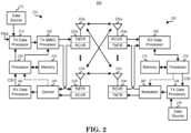
- FIG. 2 is a simplified block diagram of an embodiment of a transmitter system 210 (also known as the access network) and a receiver system 250 (also known as access terminal (AT) or user equipment (UE)) in a MIMO system 200.
- a transmitter system 210 also known as the access network
- a receiver system 250 also known as access terminal (AT) or user equipment (UE)
- traffic data for a number of data streams is provided from a data source 212 to a transmit (TX) data processor 214.
- TX transmit
- each data stream is transmitted over a respective transmit antenna.
- TX data processor 214 formats, codes, and interleaves the traffic data for each data stream based on a particular coding scheme selected for that data stream to provide coded data.
- the coded data for each data stream may be multiplexed with pilot data using OFDM techniques.
- the pilot data is typically a known data pattern that is processed in a known manner and may be used at the receiver system to estimate the channel response.
- the multiplexed pilot and coded data for each data stream is then modulated (i.e., symbol mapped) based on a particular modulation scheme (e.g., BPSK, QPSK, M-PSK, or M-QAM) selected for that data stream to provide modulation symbols.
- a particular modulation scheme e.g., BPSK, QPSK, M-PSK, or M-QAM
- the data rate, coding, and modulation for each data stream may be determined by instructions performed by processor 230.
- TX MIMO processor 220 may further process the modulation symbols (e.g., for OFDM).
- TX MIMO processor 220 then provides N T modulation symbol streams to N T transmitters (TMTR) 222a through 222t.
- TMTR TX MIMO processor 220 applies beamforming weights to the symbols of the data streams and to the antenna from which the symbol is being transmitted.
- Each transmitter 222 receives and processes a respective symbol stream to provide one or more analog signals, and further conditions (e.g., amplifies, filters, and upconverts) the analog signals to provide a modulated signal suitable for transmission over the MIMO channel.
- N T modulated signals from transmitters 222a through 222t are then transmitted from N T antennas 224a through 224t, respectively.
- the transmitted modulated signals are received by N R antennas 252a through 252r and the received signal from each antenna 252 is provided to a respective receiver (RCVR) 254a through 254r.
- Each receiver 254 conditions (e.g., filters, amplifies, and downconverts) a respective received signal, digitizes the conditioned signal to provide samples, and further processes the samples to provide a corresponding "received" symbol stream.
- An RX data processor 260 then receives and processes the N R received symbol streams from N R receivers 254 based on a particular receiver processing technique to provide N T "detected" symbol streams.
- the RX data processor 260 then demodulates, deinterleaves, and decodes each detected symbol stream to recover the traffic data for the data stream.
- the processing by RX data processor 260 is complementary to that performed by TX MIMO processor 220 and TX data processor 214 at transmitter system 210.
- a processor 270 periodically determines which pre-coding matrix to use (discussed below). Processor 270 formulates a reverse link message comprising a matrix index portion and a rank value portion.
- the reverse link message may comprise various types of information regarding the communication link and/or the received data stream.
- the reverse link message is then processed by a TX data processor 238, which also receives traffic data for a number of data streams from a data source 236, modulated by a modulator 280, conditioned by transmitters 254a through 254r, and transmitted back to transmitter system 210.
- the modulated signals from receiver system 250 are received by antennas 224, conditioned by receivers 222, demodulated by a demodulator 240, and processed by a RX data processor 242 to extract the reserve link message transmitted by the receiver system 250.
- Processor 230 determines which pre-coding matrix to use for determining the beamforming weights then processes the extracted message.
- FIG. 3 shows an alternative simplified functional block diagram of a communication device according to one embodiment of the invention.
- the communication device 300 in a wireless communication system can be utilized for realizing the UEs (or ATs) 116 and 122 in FIG. 1 or the base station (or AN) 100 in Fig. 1
- the wireless communications system is preferably the LTE system.
- the communication device 300 may include an input device 302, an output device 304, a control circuit 306, a central processing unit (CPU) 308, a memory 310, a program code 312, and a transceiver 314.
- the control circuit 306 executes the program code 312 in the memory 310 through the CPU 308, thereby controlling an operation of the communications device 300.
- the communications device 300 can receive signals input by a user through the input device 302, such as a keyboard or keypad, and can output images and sounds through the output device 304, such as a monitor or speakers.
- the transceiver 314 is used to receive and transmit wireless signals, delivering received signals to the control circuit 306, and outputting signals generated by the control circuit 306 wirelessly.
- FIG. 4 is a simplified block diagram of the program code 312 shown in FIG. 3 .
- the program code 312 includes an application layer 400, a Layer 3 portion 402, and a Layer 2 portion 404, and is coupled to a Layer 1 portion 406.
- the Layer 3 portion 402 generally performs radio resource control.
- the Layer 2 portion 404 generally performs link control.
- the Layer 1 portion 406 generally performs physical connections.
- the DOCOMO 5G White Paper introduces a 5G radio access concept that efficiently integrates both lower and higher frequency bands. Since higher frequency bands provide opportunities for wider spectrum but have coverage limitations because of higher path loss, it was proposed that a 5G system has a two-layer structure which consists of a coverage layer (e.g., consisting of macro cells) and a capacity layer (e.g., consisting of small cells or phantom cells).
- the coverage layer uses existing lower frequency bands to provide basic coverage and mobility.
- the capacity layer uses new higher frequency bands to provide high data rate transmission.
- the coverage layer could be supported by enhanced LTE RAT (Long Term Evolution Radio Access Technology), while the capacity layer could be supported by a new RAT dedicated to higher frequency bands.
- integration of the coverage and capacity layers is enabled by the tight interworking (e.g., dual connectivity) between the enhanced LTE RAT and the new RAT.
- Dual connectivity is a mode of operation for a UE (User Equipment) in RRC_CONNECTED, configured with a Master Cell Group and a Secondary Cell Group as discussed in 3GPP R2-145410.
- a Master Cell Group is a group of serving cells associated with the MeNB (Master Evolved Node B), comprising of the PCell (Primary Cell) and optionally one or more SCell (Secondary Cell).
- a Secondary Cell Group is a group of serving cells associated with the SeNB (Secondary Evolved Node B), comprising of a SpCell (Special Cell) and optionally one or more SCell (Secondary Cell).
- a UE configured with dual connectivity generally means that the UE is configured to utilize radio resources that are provided by two distinct schedulers, and located in two eNBs (MeNB and SeNB) connected via a non-ideal backhaul over the X2 interface. Furthermore, C-plane messages are communicated via MeNB. Further details of dual connectivity can be found in 3GPP R2-145410.
- a random access (RA) procedure may be performed upon SCG (Secondary Cell Group) addition, DL (downlink) data arrival, and UL (uplink) data arrival to achieve uplink synchronization.
- SCG Secondary Cell Group
- DL downlink
- UL uplink
- contention-based RA contention-free RA
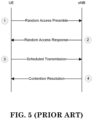
- a contention based RA procedure is shown in FIG. 5 and includes the following four steps:
- a contention-free RA procedure is shown in FIG. 6 and includes the following three steps:
- a UE After transmitting a RA preamble, a UE shall monitor a PDCCH for RA response(s) from an eNB (i.e., a base station) in a RA response window, which starts at the subframe (or TTI (Transmission Time Interval)) that contains the end of the preamble transmission plus three subframes and has length ra-ResponseWindowSize subframes, as discussed in 3GPP TS 36.321 V12.3.0. If the UE does not receive a valid RA response from the eNB within the RA response window, the UE shall retransmit a RA preamble until the maximum number of retransmissions has been reached or a valid RA response is received. Thus, it might take more than one run to complete a RA procedure. Details of a RA procedure can be found in 3GPP R2-145410 and TS 36.321 V12.3.0.
- a UE In the current LTE RAT, a UE periodically transmits a sounding reference symbol/signal (SRS) for channel quality estimation to enable frequency-selective scheduling on the uplink.
- SRS sounding reference symbol/signal
- Cells on the capacity layer may use beam forming, which is a signal processing technique used in antenna arrays for directional signal transmission or reception. This is achieved by combining elements in a phased array in such a way that signals at particular angles experience constructive interference while others experience destructive interference. Beam forming can be used at both the transmitting and receiving ends in order to achieve spatial selectivity. The improvement compared with omnidirectional reception/transmission is known as the receive/transmit gain.
- U.S. Patent Publication No. 2010/0165914 generally discloses the concept of beam division multiple access (BDMA) based on the beam forming technique.
- BDMA beam division multiple access
- a base station can communicate with a UE via a narrow beam to obtain the receive/transmit gain.
- two UEs in different beams can share the same radio resources at the same time; and thus the capacity of a mobile communication system can increase greatly.
- the base station should know the beam in which a UE can communicate with the base station.
- U.S. Patent No. 7,184,492 generally discloses using beam forming antenna to coherently transmit an information signal to a receiver using two or more directional beams.
- the phase and timing of the information signals carried by each directional beams are adjusted such that the signals arrive synchronously at the mobile terminal.
- Time synchronization may be obtained by delaying signals transmitted on selected directional beams to compensate for different propagation delays, or by preconditioning and filtering the signals using a channel coefficient matrix.
- each subframe may include two slots as follows:
- Downlink and uplink transmissions are organized into radio frames with 10 ms duration.
- Two radio frame structures are supported:
- Frame structure Type 1 is illustrated in Figure 5 .1-1 [which has been reproduced as FIG. 7 of the present application].
- Each 10 ms radio frame is divided into ten equally sized sub-frames.
- Each sub-frame consists of two equally sized slots.
- 10 subframes are available for downlink transmission and 10 subframes are available for uplink transmissions in each 10 ms interval. Uplink and downlink transmissions are separated in the frequency domain.
- Frame structure Type 2 is illustrated in Figure 5 .1-2 [which has been reproduced as FIG. 8 of the present application].
- Each 10 ms radio frame consists of two half-frames of 5 ms each.
- Each half-frame consists of eight slots of length 0.5 ms and three special fields: DwPTS, GP and UpPTS.
- the length of DwPTS and UpPTS is configurable subject to the total length of DwPTS, GP and UpPTS being equal to 1ms. Both 5ms and 10ms switch-point periodicity are supported.
- Subframe 1 in all configurations and subframe 6 in configuration with 5ms switch-point periodicity consist of DwPTS, GP and UpPTS.
- Subframe 6 in configuration with 10ms switch-point periodicity consists of DwPTS only. All other subframes consist of two equally sized slots.
- GP is reserved for downlink to uplink transition.
- Other Subframes/Fields are assigned for either downlink or uplink transmission. Uplink and downlink transmissions are separated in the time domain.
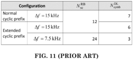
- Each downlink slot includes N symb DL OFDM symbols as shown in Figure 6 .2.2-1 (which has been reproduced as FIG. 10 of the present application) and in Table 6.2.3-1 (which has been reproduced as FIG. 11 of the present application) of 3GPP TS 36.211 V12.5.0.
- Figure 6 .2.2-1 of 3GPP TS 36.211 V12.5.0 has been reproduced as FIG. 10 of the present application.
- Table 6.2.3-1 "Physical resource blocks parameters" of 3GPP TS 36.211 V12.5.0 has been reproduced as FIG. 11 of the present application.
- a TDD (Time Division Duplex) optimized physical subframe structure for a UDN (Ultra Dense Network) system proposed by METIS Deliverable D2.4 "Proposed solutions for new radio access" is illustrated in FIG. 12 while following the main design principles listed below:
- a bi-directional (including both DL and UL resources) control part is embedded to the beginning of each subframe and time-separated from data part.
- Data part in one subframe contains data symbols for either transmission or reception.
- Demodulation Reference Signal (DMRS) symbols which are used to estimate the channel and its covariance matrix, could be located, for example, in the first OFDM (Orthogonal Frequency-Division Multiplexing) symbol in the dynamic data part and could be precoded with the same vector or matrix as data.
- DMRS Demodulation Reference Signal
- Short subframe lengths such as e.g. 0.25 ms on cmW frequencies when assuming 60 kHz SC spacing, are feasible.
- the frame numerology is further scaled when moving to mmW, leading to even shorter frame length (e.g., in the order of 50 ⁇ s).
- the bi-directional control part of the subframe allows the devices in the network to both receive and send control signals, such as scheduling requests (SRs) and scheduling grants (SGs), in every subframe.
- control signals such as scheduling requests (SRs) and scheduling grants (SGs)
- SRs scheduling requests
- SGs scheduling grants
- the control part may also contain reference signals (RS) and synchronization signals used for cell detection and selection, scheduling in frequency domain, precoder selection, and channel estimation.
- RS reference signals
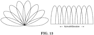
- a potential beam pattern applied by a base station for transmission and/or reception in a cell could be fixed as shown in FIG. 13 . That is the number of beams and the beam-widths of beams in a cell are fixed, while the beam-widths of beams in different directions could be different. Due to multiple propagation paths or overlapping between two neighboring beams, it is likely that multiple beams would be used by a UE for communicating with the base station. In this situation, the base station needs to determine the beam set used by a UE (e.g., by monitoring an uplink signal transmitted from the UE).
- the base station Since a random access (RA) procedure needs to be performed by a UE before data can be transferred via a cell, it would be beneficial for the base station to determine the initial beam set of a UE during the RA procedure, especially if a dedicated RA preamble is used. For example, the beam set could be determined according to the beam(s) via which the dedicated RA preamble(s) is (are) received from the UE.
- RA random access
- the base station would miss a dedicated RA preamble transmitted from a UE if none of the beams points to the direction of the UE when the RA preamble is transmitted.
- several runs of random access may be required to successfully complete a RA procedure, which would cause latency to the subsequent data transfer via the cell.
- resource sharing between the concerned UE and other UEs in the cell would be delayed. This is undesirable.
- a potential solution is for a UE to transmit multiple RA preambles in a short period of time before it starts monitoring a PDCCH for RA response(s) from the base station.
- the base station would then be allowed to complete scanning all beams of the cell so as to receive at least one RA preamble from the UE.
- a RA procedure could be successfully completed without too much latency.
- FIG. 14 shows an example of this solution according to one exemplary embodiment according to the invention.
- the UE is located in beams X and Y.
- the base station monitors preambles at T1, T2, and T3 for receiving preambles via different beams of the cell. In this example, multiple beams could be monitored at each time.
- the preamble transmitted by the UE is received via beams X and Y at T2.
- the beam set of the UE is ⁇ X , Y ⁇ . It is possible that preambles transmitted by the UE could be received at different times.
- the base station does not transmit any RA response to the UE until all the multiple beams of the cell has been monitored. In other words, the base station transmits a RA response to the UE after all beams of the cell has been monitored if there is any RA preamble received.
- the base station determines a beam set of the UE according to the beam(s) via which RA preamble(s) is (are) received from the UE. After the initial beam set of a UE has been determined, the base station needs to continue tracking the UE and update the beam set due to UE mobility. It seems possible for the base station to track the beam set of a UE based on periodic SRS-like reference signal (RS) transmissions from the UE, wherein it could be sufficient for the SRS-like RS to cover narrower bandwidth. Then, the beam set is updated according to the beam(s) via which the RS(s) is (are) received from the UE.
- RS SRS-like reference signal
- FIG. 15 illustrates an example of this solution according to one exemplary embodiment according to the invention.
- a UE periodically transmits RSs for beam set update after an initial beam set of the UE has been determined by a base station.
- the base station monitors RS at T1, T2, and T3 via different beams of the cell and RS is received via beams X and Y at T2.
- the beam set of the UE is updated to ⁇ X , Y ⁇ . Due to UE mobility, RS is received via beam Z alone at T6 during the second period. As a result, the new beam set is ⁇ Z ⁇ . In this example, multiple beams are monitored at each time. It is also possible that RSs transmitted by the UE could be received at different times.
- each UE would be tracked individually at UE specific times and is allocated with RS resources, wherein the RS resources define periodic resources for RS transmissions and there are multiple occasions with resources for transmissions of multiple RSs by the UE in each RS period.
- an occasion refers to a time unit (e.g., a symbol, a time slot, or a subframe).
- all UEs (which need to be tracked in the cell) are tracked at common occasions so that the base station only needs to monitor those occasions to receive RSs transmitted by all UEs.
- all UEs share one RS period.
- UEs may have different RS periods, while timings of all RS periods are synchronized. For example, there is a nominal RS period and a RS period of each UE is a multiple of the nominal RS period. FIG. 16 shows examples of these two options.
- each occasion of a RS period is shared by all UEs which need to be tracked (in case there are sufficient RS resources on each occasion for all UEs).
- different occasions of the RS period are occupied by different UEs.
- each UE would only need to transmit a single RS for base station to determine the beam set of the UE. Similar methods for beam tracking described above for a cell with analog beam-former are also applicable to a cell with digital beam-former. In this situation (i.e., a cell with digital beam-former), the base station would only need to allocate RS resources to each UE for one single RS transmission on one occasion in each RS period for beam tracking if digital beam-former is used. It is possible that all UEs share one RS period or UEs may have different RS periods. In one embodiment, each occasion of a RS period is shared by all LTEs which need to be tracked. In another embodiment, different occasions of the RS period are occupied by different UEs.
- a TDD optimized physical subframe structure for a UDN system is proposed by METIS Deliverable D2.4 "Proposed solutions for new radio access".
- an uplink control part may need to contain PUCCH (Physical Uplink Control Channel) signaling for HARQ ACK/NACK (Hybrid Automatic Repeat Request Acknowledgement/Negative Acknowledgement) and RS for UE beam set detection.
- PUCCH Physical Uplink Control Channel
- HARQ ACK/NACK Hybrid Automatic Repeat Request Acknowledgement/Negative Acknowledgement
- RS for UE beam set detection.
- the UE would send a HARQ ACK/NACK in response to a downlink transmission from a base station.
- PUCCH signaling for HARQ ACK/NACK and RS for UE beam set detection may be transmitted by different UEs and received by the base station via different beams, it is more flexible in term of scheduling to have at least two symbols in the uplink control part: (1) one symbol contains RS resources for UE beam set detection and (2) another symbol not contain any RS resource for UE beam set detection.
- the symbol which contains RS resources for UE beam set detection may also contain resources for HARQ ACK/NACK signaling. This embodiment would be feasible if the beam(s) used by the base station to receive PUCCH signaling for HARQ ACK/NACK is the same as the beam(s) used for monitoring RS for UE beam set detection. Otherwise, the base station may miss the PUCCH signaling for HARQ ACK/NACK, which would degrade the transmission performance.
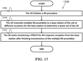
- FIG. 17 is a flow chart 1700, outlining a method for preamble transmissions by a UE in a cell of a wireless communication system, wherein there are multiple beams in the cell.
- the UE initiates a random access (RA) procedure.
- the UE transmits multiple RA preambles to a base station of the cell at different occasions for the base station to determine a beam set of the UE.
- RA random access
- the UE starts monitoring a Physical Downlink Control Channel (PDCCH) for RA response reception from the base station after finishing transmissions of the multiple RA preambles.
- PDCCH Physical Downlink Control Channel
- the UE monitors the PDCCH for RA response reception in a RA response window.
- the RA response window could start at a subframe that contains an end of a transmission of the last RA preamble of the multiple RA preambles plus a number of subframes and has a length configured to the UE. More specifically, the RA response window could start at a subframe that contains the end of the transmission of the last RA preamble transmission plus three (3) subframes. Furthermore, the UE could receive one RA response for the UE within the RA response window.
- the UE could decode each RA response individually without combining multiple RA responses.
- the UE could be within normal coverage of the base station, such as the received signal quality of the UE from the base station is above a threshold, so that the UE could decode each RA response individually without combining multiple RA responses.
- the device 300 includes a program code 312 stored in memory 310 of the transmitter.
- the CPU 308 could execute program code 312 (i) to initiate a RA procedure, (ii) to transmit multiple RA preambles to a base station of the cell at different occasions for the base station to determine a beam set of the UE, and (iii) to start monitoring a Physical Downlink Control Channel (PDCCH) for RA response reception from the base station after finishing transmissions of the multiple RA preambles.
- the CPU 308 can execute the program code 312 to perform all of the above-described actions and steps or others described herein.
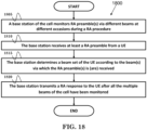
- FIG. 18 is a flow chart 1800 from the perspective of a base station.
- the flow chart 1800 outlines a method for beam finding in a cell of a wireless communication system, wherein there are multiple beams in the cell.
- a base station of the cell monitors RA preamble(s) via different beams at different occasions during a RA procedure.
- the base station receives at least a RA preamble from a UE.
- the base station determines a beam set of the UE according to the beam(s) via which the RA preamble(s) is (are) received.
- the base station transmits a RA response to the UE after all the multiple beams of the cell have been monitored.
- the base station transmits only one RA response to the UE in response to receptions of multiple RS preambles from the UE during the RA procedure.
- an occasion refers to a time unit (e.g., a symbol, a time slot, or a subframe).
- the RA preamble is dedicated to the UE.
- the RA preamble being dedicated to the UE could mean the RA preamble of the UE is distinguishable from RA preambles of other UEs in the cell in at least one of following domains: time domain, frequency domain, and sequence domain.
- the device 300 includes a program code 312 stored in memory 310 of the transmitter.
- the CPU 308 could execute program code 312 (i) to monitor RA preamble(s) via different beams at different occasions during a RA procedure, (ii) to receive at least a RA preamble from a UE, and (iii) to determine a beam set of the UE according to the beam(s) via which the RA preamble(s) is (are) received.
- the CPU 308 could execute program code 312 to transmit a RA response to the UE after all the multiple beams of the cell have been monitored.
- the CPU 308 can execute the program code 312 to perform all of the above-described actions and steps or others described herein.
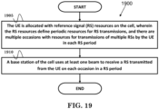
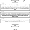
- FIG. 19 is a flow chart 1900, outlining a method for determining a beam set used by a UE in a cell of a wireless communication system, wherein there are multiple beams in the cell.
- the method outlined in the flow chart 1900 could be applied by a base station in distributed and centralized settings.
- the UE is allocated with reference signal (RS) resources on the cell, wherein the RS resources define periodic resources for RS transmissions, and there are multiple occasions with resources for transmissions of multiple RSs by the UE in each RS period.
- RS reference signal
- a base station of the cell uses at least one beam to receive a RS transmitted from the UE on each occasion in a RS period.
- the base station uses different sets of beams to receive RSs transmitted from the UE on different occasions in the RS period.
- the total beams could be used to receive RSs transmitted from the UE in the RS period cover all beams of the cell.
- the multiple occasions could be UE specific. Alternatively or additionally preferably, the multiple occasions could be shared by UEs which need to be tracked.
- the device 300 includes a program code 312 stored in memory 310 of the transmitter.
- the CPU 308 could execute program code 312 (i) to enable the UE to be allocated with RS resources on the cell, wherein the RS resources define periodic resources for RS transmissions, and there are multiple occasions with resources for transmissions of multiple RSs by the UE in each RS period, and (ii) to enable a base station to use at least one beam to receive a RS transmitted from the UE on each occasion in a RS period.
- the CPU 308 can execute the program code 312 to perform all of the above-described actions and steps or others described herein.
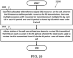
- FIG. 20 is a flow chart 2000, outlining a method for determining beam sets used by UEs in a cell of a wireless communication system, wherein each UE has its own beam set and there are multiple beams in the cell.
- the method outlined in the flow chart 2000 could be applied by a base station in a centralized setting and to the same RS period for all UEs.
- each UE is allocated with reference signal (RS) resources on the cell, wherein the RS resources define periodic resources for RS transmissions, there are multiple occasions with resources for transmissions of multiple RSs by each UE in each RS period, and one RS period is shared by UEs which need to be tracked.
- a base station of the cell uses at least one beam to receive RSs transmitted from UEs on each occasion in the RS period, wherein the total beams used to receive the RSs transmitted from UEs in the RS period cover all beams of the cell.
- the base station determines the beam set used by the UE according to the beam(s) via which RS(s) is (are) received from the UE.
- the base station could transmit a message to allocate the RS resources to the UE (for single connectivity).
- a second base station of a second cell serving the UE could transmit a message to allocate the RS resources to the UE (for dual connectivity).
- the beam set used by a UE contains at least one beam.
- an occasion refers to a time unit (e.g., a symbol, a time slot, or a subframe).
- the device 300 includes a program code 312 stored in memory 310 of the transmitter.
- the CPU 308 could execute program code 312 (i) to enable each UE to be allocated with RS resources on the cell, wherein the RS resources define periodic resources for RS transmissions, there are multiple occasions with resources for transmissions of multiple RSs by each UE in each RS period, and one RS period is shared by UEs which need to be tracked, and (ii) to enable a base station of the cell to use at least one beam to receive a RS transmitted from the UE on each occasion in a RS period.
- the CPU 308 can execute the program code 312 to perform all of the above-described actions and steps or others described herein.
- FIG. 21 is a flow chart 2100, in accordance with an exemplary embodiment according to the invention, outlining a method for determining beam sets used by UEs in a cell from the perspective of a base station.
- the method outlined in the flow chart 2100 could be applied by a base station in a centralized setting and to a UE-specific RS period.
- each UE is allocated with reference signal (RS) resources on the cell, wherein the RS resources define periodic resources for RS transmissions, there are multiple occasions with resources for transmissions of multiple RSs by each UE in each RS period, and a RS period of each UE is a multiple of a nominal RS period.
- a base station of the cell uses at least one beam to receive RSs transmitted from UEs on each occasion in a tracking period, wherein the total beams used to receive the RSs transmitted from UEs in the tracking period cover all beams of the cell.
- the tracking period could be determined according to the RS periods of UEs which need to be tracked.
- the tracking period could be a multiple of the nominal RS period.
- the tracking period could be equal to the nominal RS period.
- the base station determines the beam set used by the UE according to the beam(s) via which RS(s) is (are) received from the UE.
- the base station transmits a message to allocate the RS resources to the LTE (for single connectivity).
- a second base station of a second cell serving the UE could transmit a message to allocate the RS resources to the UE (for dual connectivity).
- the beam set used by a UE contains at least one beam.
- an occasion refers to a time unit (e.g., a symbol, a time slot, or a subframe).
- the device 300 includes a program code 312 stored in memory 310 of the transmitter.
- the CPU 308 could execute program code 312 (i) to enable each UE to be allocated with RS resources on the cell, wherein the RS resources define periodic resources for RS transmissions, there are multiple occasions with resources for transmissions of multiple RSs by each UE in each RS period, and a RS period of each UE is a multiple of a nominal RS period, (ii) to enable a base station of the cell to use at least one beam to receive RSs transmitted from UEs on each occasion in a tracking period, wherein the total beams used to receive the RSs transmitted from UEs in the tracking period cover all beams of the cell, and (iii) to enable the base station to determine the beam set used by the UE according to the beam(s) via which RS(s) is (are) received from the UE.
- the CPU 308 can execute the program code 312 to perform all of the above-
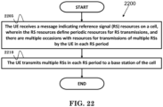
- FIG. 22 is a flow chart 2200, in accordance with an exemplary embodiment according to the invention, outlining a method for RS transmissions by a UE in a cell of a wireless system.
- the UE receives a message indicating reference signal (RS) resources on a cell, wherein the RS resources define periodic resources for RS transmissions, and there are multiple occasions with resources for transmissions of multiple RSs by the UE in each RS period.
- the UE transmits multiple RSs in each RS period to a base station of the cell.
- RS reference signal
- the UE receives the message from the base station (for single connectivity). Alternatively or additionally, the UE receives the message from a second base station of a second cell serving the UE (for dual connectivity). In addition, there are multiple beams in the cell.
- an occasion could refer to a time unit in FDD (Frequency Division Duplex) mode (e.g., a symbol, a time slot, or a subframe).
- FDD Frequency Division Duplex
- an occasion could refer to a time unit in TDD (Time Division Duplex) mode (e.g., a symbol in a normal subframe, a time slot, or a subframe).
- TDD Time Division Duplex
- the multiple occasions are contiguous, and each occasion of a RS period could be shared by all UEs which need to be tracked.
- different occasions of the RS period could be occupied by different UEs.
- the RSs could be dedicated to a particular UE, which means the RSs of the particular UE are distinguishable from RSs of other UEs in the cell in at least one of following domains: time domain, frequency domain, and/or sequence domain.
- the device 300 includes a program code 312 stored in memory 310 of the transmitter.
- the CPU 308 could execute program code 312 (i) to receive a message indicating reference signal (RS) resources on a cell, wherein the RS resources define periodic resources for RS transmissions, and there are multiple occasions with resources for transmissions of multiple RSs by the UE in each RS period, and (ii) to transmit multiple RSs in each RS period to a base station of the cell.
- the CPU 308 can execute the program code 312 to perform all of the above-described actions and steps or others described herein.
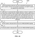
- FIG. 23 is a flow chart 2300, outlining a method for determining beam sets used by UEs in a cell of a wireless system, wherein each UE has its own beam set and there are multiple beams in the cell.
- the method outlined in the flow chart 2300 could be applied by a base station in a centralized setting and to the same RS period for all UEs.
- each UE is allocated with periodic RS resources on the cell for RS transmissions, wherein UEs which need to be tracked in the cell share one RS period.
- a base station of the cell uses all beams of the cell to receive RSs transmitted from UEs on each occasion with RS resources in each RS period.
- the RS resources in each RS period for UEs which need to be tracked are located in one subframe. Furthermore, preferably there is at least one occasion with RS resources in each RS period.
- the base station determines the beam set used by the UE according to the beam(s) via which RS(s) is (are) received from the UE.
- the base station could transmit a message to allocate the RS resources to the UE (for single connectivity).
- a second base station of a second cell serving the UE could transmit a message to allocate the RS resources to the UE (for dual connectivity).
- the beam set used by a UE contains at least one beam.
- the RSs are dedicated to the UE, which means the RSs of the UE are distinguishable from RSs of other UEs in the cell in at least one of following domains: time domain, frequency domain, and sequence domain.
- an occasion refers to a time unit e.g. a symbol, a time slot, or a subframe.
- each occasion of a RS period could be shared by all UEs which need to be tracked.
- different occasions of the RS period could be occupied by different UEs.
- the device 300 includes a program code 312 stored in memory 310 of the transmitter.
- the CPU 308 could execute program code 312 (i) to allocate each UE with periodic RS resources on the cell for RS transmissions, wherein UEs which need to be tracked in the cell share one RS period, and (ii) to enable a base station of the cell to use all beams of the cell to receive RSs transmitted from UEs on each occasion with RS resources in each RS period.
- the CPU 308 could further execute program code 312 to enable the base station to determine the beam set used by the UE according to the beam(s) via which RS(s) is (are) received from the UE.
- the CPU 308 can execute the program code 312 to perform all of the above-described actions and steps or others described herein.
- FIG. 24 is a flow chart 2400, outlining a method for determining beam sets used by UEs in a cell of a wireless system, wherein each UE has its own beam set and there are multiple beams in the cell.
- the method outlined in the flow chart 2400 could be applied by a base station in a centralized setting and to a UE-specific RS period.
- each UE is allocated with periodic RS resources on the cell for RS transmissions, wherein a RS period of the UE is a multiple of a nominal RS period.
- a base station of the cell uses all beams of the cell to receive RSs transmitted from UEs on each occasion with RS resources in each tracking period.
- the RS resources in each tracking period for UEs which need to be tracked are located in one subframe. Furthermore, preferably there is at least one occasion with RS resources in each tracking period.
- the tracking period is determined according to the RS periods of UEs which need to be tracked in the cell. Furthermore, preferably the tracking period is a multiple of the nominal RS period. In addition, preferably the tracking period is equal to the nominal RS period.
- the base station determines the beam set used by the UE according to the beam(s) via which RS(s) is (are) received from the LTE.
- the base station could transmit a message to allocate the RS resources to the UE (for single connectivity).
- a second base station of a second cell serving the UE could transmit a message to allocate the RS resources to the UE (for dual connectivity).
- the beam set used by a UE contains at least one beam.
- the RSs are dedicated to the UE, which means the RSs of the UE are distinguishable from RSs of other UEs in the cell in at least one of following domains: time domain, frequency domain, and sequence domain.
- an occasion refers to a time unit e.g. a symbol, a time slot, or a subframe.
- each occasion of a RS period could be shared by all UEs which need to be tracked.
- different occasions of the RS period could be occupied by different UEs.
- the device 300 includes a program code 312 stored in memory 310 of the transmitter.
- the CPU 308 could execute program code 312 (i) to allocate each UE with periodic RS resources on the cell for RS transmissions, wherein a RS period of the UE is a multiple of a nominal RS period, and (ii) to enable a base station of the cell to use all beams of the cell to receive RSs transmitted from UEs on each occasion with RS resources in each tracking period.
- the CPU 308 could further execute program code 312 to enable the base station to determine the beam set used by the UE according to the beam(s) via which RS(s) is (are) received from the UE.
- the CPU 308 can execute the program code 312 to perform all of the above-described actions and steps or others described herein.
- FIG. 25 is a flow chart 2500, outlining a method for defining a subframe structure for beam detection.
- a cell communicates with UEs in the cell via downlink transmissions and uplink receptions, wherein the downlink transmissions and uplink receptions are organized into radio frames.
- a radio frame is constructed with multiple subframes, wherein a subframe in the radio frame includes at least an uplink control part, and the uplink control part includes at least: (1) a first symbol, which is allocated with resources for the UEs to transmit reference signals for the cell to determine beam sets of the UEs, and (2) a second symbol, which is not allocated with resources for the UEs to transmit the reference signals for the cell to determine beam set of the UEs.
- a first symbol is allocated with resources for HARQ ACK/NACK (Hybrid Automatic Repeat Request Acknowledgement/Negative Acknowledgement) signaling in step 2515.
- a second symbol is allocated with resources for HARQ ACK/NACK signaling in step 2520.
- the device 300 includes a program code 312 stored in memory 310 of the transmitter.
- the CPU 308 could execute program code 312 (i) to enable a cell to communicate with UEs via downlink transmissions and uplink receptions, wherein the downlink transmissions and uplink receptions are organized into radio frames, and (ii) to construct a radio frame with multiple subframes, wherein a subframe in the radio frame includes at least an uplink control part, and the uplink control part includes at least: (1) a first symbol, which is allocated with resources for the UEs to transmit reference signals for the cell to determine beam sets of the UEs, and (2) a second symbol, which is not allocated with resources for the UEs to transmit the reference signals for the cell to determine beam sets of the UEs.
- the CPU 308 could further execute program code 312 to allocate the first symbol and the second symbol with resources for HARQ ACK/NACK signaling.
- the CPU 308 can execute the program code 312 to perform all of the above-described actions and steps or others described herein.
- FIG. 26 is a flow chart 2600, outlining a method for defining a subframe structure for beam detection.
- a UE communicates with a cell via uplink transmissions and downlink receptions, wherein the uplink transmissions and downlink receptions are organized into radio frames.
- a radio frame is constructed with multiple subframes, wherein a subframe in the radio frame includes at least an uplink control part, and the uplink control part includes at least: (1) a first symbol, which is allocated with resources for the UE to transmit reference signals for the cell to determine a beam set of the UE, and (2) a second symbol, which is not allocated with resources for the UE to transmit the reference signals for the cell to determine the beam set of the UE.
- a first symbol is allocated with resources for HARQ ACK/NACK signaling in step 2615.
- a second symbol is allocated with resources for HARQ ACK/NACK signaling in step 2520.
- the device 300 includes a program code 312 stored in memory 310 of the transmitter.
- the CPU 308 could execute program code 312 (i) to enable a UE to communicate with a cell via uplink transmissions and downlink receptions, wherein the uplink transmissions and downlink receptions are organized into radio frames, and (ii) to construct a radio frame with multiple subframes, wherein a subframe in the radio frame includes at least an uplink control part, and the uplink control part includes at least: (1) a first symbol, which is allocated with resources for the UE to transmit reference signals for the cell to determine a beam set of the UE, and (2) a second symbol, which is not allocated with resources for the UE to transmit the reference signals for the cell to determine the beam set of the UE.
- the CPU 308 could further execute program code 312 to allocate the first symbol and the second symbol with resources for HARQ ACK/NACK signaling.
- the CPU 308 can execute the program code 312 to perform all of the above-described actions and steps or others described herein.
- the subframe in the radio frame could contain a downlink control part and/or a data part.
- the subframe structure could be used in a TDD (Time Division Duplex) mode.
- the downlink transmissions and uplink receptions relevant to the UE could be performed by the cell on multiple beams in a beam set of the UE.
- a total number of beams in the cell could be fixed.
- the direction and/or the width of each beam in the cell could be fixed.
- the first and the second exemplary embodiments can be combined to implement a system of a user equipment and a base station where the base station can determine a beam set of the user equipment, wherein preferably the features of any one or any combination of the third to tenth exemplary embodiments might be implemented in order to further enhance this system.
- an apparatus may be implemented or a method may be practiced using any number of the aspects set forth herein.
- such an apparatus may be implemented or such a method may be practiced using other structure, functionality, or structure and functionality in addition to or other than one or more of the aspects set forth herein.
- concurrent channels may be established based on pulse repetition frequencies.
- concurrent channels may be established based on pulse position or offsets.
- concurrent channels may be established based on time hopping sequences.
- concurrent channels may be established based on pulse repetition frequencies, pulse positions or offsets, and time hopping sequences.
- the various illustrative logical blocks, modules, and circuits described in connection with the aspects disclosed herein may be implemented within or performed by an integrated circuit ("IC"), an access terminal, or an access point.
- the IC may comprise a general purpose processor, a digital signal processor (DSP), an application specific integrated circuit (ASIC), a field programmable gate array (FPGA) or other programmable logic device, discrete gate or transistor logic, discrete hardware components, electrical components, optical components, mechanical components, or any combination thereof designed to perform the functions described herein, and may execute codes or instructions that reside within the IC, outside of the IC, or both.
- a general purpose processor may be a microprocessor, but in the alternative, the processor may be any conventional processor, controller, microcontroller, or state machine.
- a processor may also be implemented as a combination of computing devices, e.g., a combination of a DSP and a microprocessor, a plurality of microprocessors, one or more microprocessors in conjunction with a DSP core, or any other such configuration.
- a software module e.g., including executable instructions and related data
- other data may reside in a data memory such as RAM memory, flash memory, ROM memory, EPROM memory, EEPROM memory, registers, a hard disk, a removable disk, a CD-ROM, or any other form of computer-readable storage medium known in the art.
- a sample storage medium may be coupled to a machine such as, for example, a computer/processor (which may be referred to herein, for convenience, as a "processor") such the processor can read information (e.g., code) from and write information to the storage medium.
- a sample storage medium may be integral to the processor.
- the processor and the storage medium may reside in an ASIC.
- the ASIC may reside in user equipment.
- the processor and the storage medium may reside as discrete components in user equipment.
- any suitable computer-program product may comprise a computer-readable medium comprising codes relating to one or more of the aspects of the disclosure.
- a computer program product may comprise packaging materials.
Landscapes
- Engineering & Computer Science (AREA)
- Computer Networks & Wireless Communication (AREA)
- Signal Processing (AREA)
- Mobile Radio Communication Systems (AREA)
Claims (11)
- Procédé pour déterminer un ensemble de faisceaux utilisé par un équipement utilisateur, également appelé UE, dans une cellule d'un système de communication sans fil, dans lequel il y a plusieurs faisceaux dans la cellule, comprenant :une station de base de la cellule détermine un ensemble de faisceaux initial de l'UE selon un/des faisceau(x) par lequel/lesquels des préambules d'accès aléatoire transmis par l'UE au cours d'une procédure d'accès aléatoire sont reçus de la station de base ;caractérisé en ce qu'il comprend en outre :la station de base attribue (1905) à l'UE des ressources de signal de référence, également appelé RS, sur la cellule après la procédure d'accès aléatoire,dans lequel les ressources RS définissent des ressources périodiques pour des transmissions RS avec une première période de répétition, et il y a plusieurs symboles contigus avec des ressources RS attribuées pour des transmissions de plusieurs RS par l'UE dans chaque première période de répétition ;la station de base de la cellule utilise au moins un faisceau (1910) pour recevoir un RS transmis par l'UE sur chaque symbole des plusieurs symboles contigus dans chaque première période de répétition ; etla station de base met à jour l'ensemble de faisceaux initial de l'UE selon ledit au moins un faisceau par lequel ledit RS sur chaque symbole des plusieurs symboles contigus dans chaque première période de répétition est reçu de l'UE.
- Procédé de la revendication 1, comprenant en outre : la station de base utilise différents ensembles de faisceaux pour recevoir des RS transmis par l'UE sur différents symboles dans chaque première période de répétition.
- Procédé de la revendication 1 ou 2, dans lequel la totalité des faisceaux utilisés pour recevoir des RS transmis par l'UE dans chaque première période de répétition couvrent tous les faisceaux de la cellule.
- Procédé de l'une des revendications 1 à 3, dans lequel les plusieurs symboles contigus avec des ressources pour des transmissions RS sont spécifiques à l'UE.
- Procédé de l'une des revendications 1 à 4, dans lequel les RS sont dédiés à l'UE.
- Procédé de la revendication 5, dans lequel les RS dédiés à l'UE signifient que les RS de l'UE peuvent être distingués des RS d'autres UE dans la cellule dans au moins l'un des domaines suivants : domaine temporel, domaine fréquentiel, et domaine de séquence.
- Procédé pour un équipement utilisateur, également appelé UE, dans une cellule d'un système de communication sans fil, comprenant :l'UE transmet plusieurs préambules d'accès aléatoire au cours d'une procédure d'accès aléatoire pour une station de base de la cellule pour déterminer un ensemble de faisceaux initial de l'UE ;caractérisé en ce qu'il comprend en outre :l'UE reçoit un message indiquant des ressources RS attribuées à l'UE sur une cellule (2205) après la procédure d'accès aléatoire,dans lequel les ressources RS définissent des ressources périodiques pour des transmissions RS avec une première période de répétition, etil y a plusieurs symboles contigus avec des ressources RS attribuées pour des transmissions de plusieurs RS par l'UE dans chaque première période de répétition ; etledit procédé comprend en outre le fait que l'UE transmet plusieurs RS sur les plusieurs symboles contigus dans chaque première période de répétition à la station de base pour mettre à jour l'ensemble de faisceaux initial de l'UE (2210).
- Procédé de la revendication 7, dans lequel les plusieurs symboles contigus avec des ressources pour des transmissions RS sont spécifiques à l'UE.
- Procédé de la revendication 7 ou 8, dans lequel les RS sont dédiés à l'UE.
- Procédé de la revendication 9, dans lequel les RS dédiés à l'UE signifient que les RS de l'UE peuvent être distingués des RS d'autres UE dans la cellule dans au moins l'un des domaines suivants : domaine temporel, domaine fréquentiel, et domaine de séquence.
- Équipement utilisateur, également appelé UE, (300), comprenant :un circuit de commande (306) ;un processeur (308) installé dans le circuit de commande (306) ; etune mémoire (310) installée dans le circuit de commande (306) et couplée au processeur (308) ;caractérisé en ce que le processeur (308) est configuré pour exécuter un code de programme (312) stocké dans la mémoire (310) pour effectuer les étapes du procédé telles que définies dans l'une quelconque des revendications 7 à 10.
Applications Claiming Priority (4)
| Application Number | Priority Date | Filing Date | Title |
|---|---|---|---|
| US201562107792P | 2015-01-26 | 2015-01-26 | |
| US201562107814P | 2015-01-26 | 2015-01-26 | |
| US201562166368P | 2015-05-26 | 2015-05-26 | |
| EP16152419.4A EP3048851B1 (fr) | 2015-01-26 | 2016-01-22 | Procédé et appareil de détection de faisceau dans un système de communication sans fil |
Related Parent Applications (2)
| Application Number | Title | Priority Date | Filing Date |
|---|---|---|---|
| EP16152419.4A Division-Into EP3048851B1 (fr) | 2015-01-26 | 2016-01-22 | Procédé et appareil de détection de faisceau dans un système de communication sans fil |
| EP16152419.4A Division EP3048851B1 (fr) | 2015-01-26 | 2016-01-22 | Procédé et appareil de détection de faisceau dans un système de communication sans fil |
Publications (2)
| Publication Number | Publication Date |
|---|---|
| EP3328151A1 EP3328151A1 (fr) | 2018-05-30 |
| EP3328151B1 true EP3328151B1 (fr) | 2023-10-18 |
Family
ID=55446581
Family Applications (3)
| Application Number | Title | Priority Date | Filing Date |
|---|---|---|---|
| EP16152419.4A Active EP3048851B1 (fr) | 2015-01-26 | 2016-01-22 | Procédé et appareil de détection de faisceau dans un système de communication sans fil |
| EP18152090.9A Active EP3328152B1 (fr) | 2015-01-26 | 2016-01-22 | Procédé et appareil de détection de faisceau dans un système de communication sans fil |
| EP18152087.5A Active EP3328151B1 (fr) | 2015-01-26 | 2016-01-22 | Procédé et appareil de détection de faisceau dans un système de communication sans fil |
Family Applications Before (2)
| Application Number | Title | Priority Date | Filing Date |
|---|---|---|---|
| EP16152419.4A Active EP3048851B1 (fr) | 2015-01-26 | 2016-01-22 | Procédé et appareil de détection de faisceau dans un système de communication sans fil |
| EP18152090.9A Active EP3328152B1 (fr) | 2015-01-26 | 2016-01-22 | Procédé et appareil de détection de faisceau dans un système de communication sans fil |
Country Status (3)
| Country | Link |
|---|---|
| US (4) | US10925061B2 (fr) |
| EP (3) | EP3048851B1 (fr) |
| ES (3) | ES2963430T3 (fr) |
Families Citing this family (36)
| Publication number | Priority date | Publication date | Assignee | Title |
|---|---|---|---|---|
| US9936519B2 (en) | 2015-03-15 | 2018-04-03 | Qualcomm Incorporated | Self-contained time division duplex (TDD) subframe structure for wireless communications |
| US10342012B2 (en) | 2015-03-15 | 2019-07-02 | Qualcomm Incorporated | Self-contained time division duplex (TDD) subframe structure |
| US10075970B2 (en) * | 2015-03-15 | 2018-09-11 | Qualcomm Incorporated | Mission critical data support in self-contained time division duplex (TDD) subframe structure |
| US9814058B2 (en) | 2015-05-15 | 2017-11-07 | Qualcomm Incorporated | Scaled symbols for a self-contained time division duplex (TDD) subframe structure |
| US9992790B2 (en) | 2015-07-20 | 2018-06-05 | Qualcomm Incorporated | Time division duplex (TDD) subframe structure supporting single and multiple interlace modes |
| US11005628B2 (en) | 2015-08-04 | 2021-05-11 | Futurewei Technologies, Inc. | Device, network, and method for wideband LTE single OFDM symbol uplink transmission |
| US11589347B2 (en) * | 2015-11-06 | 2023-02-21 | Motorola Mobility Llc | Method and apparatus for low latency transmissions |
| WO2017185259A1 (fr) * | 2016-04-27 | 2017-11-02 | 华为技术有限公司 | Procédé de transmission d'informations dans un réseau de communication optique sans fil, coordinateur et noeud terminal |
| WO2018048182A1 (fr) | 2016-09-12 | 2018-03-15 | Lg Electronics Inc. | Transmission de préambule d'accès aléatoires multiples pour une procédure d'accès aléatoire unique |
| EP3536093B1 (fr) * | 2016-11-04 | 2022-06-22 | Telefonaktiebolaget LM Ericsson (publ) | Améliorations apportées à des signaux de référence de mobilité pour une surveillance de liaison radio dans un système basé sur un faisceau |
| KR102092560B1 (ko) * | 2016-11-04 | 2020-03-25 | 주식회사 케이티 | 무선 통신에서 멀티 빔 기반 랜덤 액세스 절차를 수행하는 방법 및 장치 |
| CN108235444B (zh) | 2016-12-12 | 2021-09-10 | 北京三星通信技术研究有限公司 | 随机接入的方法及基站设备、用户设备 |
| AU2016432983A1 (en) | 2016-12-21 | 2019-08-01 | Guangdong Oppo Mobile Telecommunications Corp., Ltd. | Signal transmission method, terminal device and network device |
| WO2018123483A1 (fr) * | 2016-12-28 | 2018-07-05 | シャープ株式会社 | Dispositif terminal, dispositif de station de base et procédé de communication |
| US10841954B2 (en) * | 2017-01-13 | 2020-11-17 | Acer Incorporated | Device of handling a random access procedure |
| CN108366418B (zh) * | 2017-01-26 | 2023-12-19 | 华为技术有限公司 | 节点和功率控制方法 |
| US10506576B2 (en) | 2017-01-27 | 2019-12-10 | Qualcomm Incorporated | Multi-link new radio (NR)-physical downlink control channel (PDCCH) design |
| US20180227772A1 (en) * | 2017-02-06 | 2018-08-09 | Mediatek Inc. | Mechanism for Beam Reciprocity Determination and Uplink Beam Management |
| US10547375B1 (en) | 2017-02-13 | 2020-01-28 | Lockheed Martin Corporation | Efficient resource allocation for satellite LTE networks |
| CN117377120A (zh) | 2017-05-05 | 2024-01-09 | 诺基亚技术有限公司 | 关于多prach前导码和随机接入响应 |
| CN109417804B (zh) * | 2017-05-12 | 2021-03-30 | 华为技术有限公司 | 一种初始接入方法及设备 |
| CN110547033A (zh) * | 2017-07-20 | 2019-12-06 | Oppo广东移动通信有限公司 | 用于随机接入的方法和终端设备 |
| CN109392060B (zh) | 2017-08-02 | 2020-07-28 | 维沃移动通信有限公司 | 一种rar的监听方法、发送方法、相关设备及系统 |
| EP3668247A4 (fr) * | 2017-08-10 | 2021-03-10 | Beijing Xiaomi Mobile Software Co., Ltd. | Procédé et dispositif d'accès aléatoire, équipement d'utilisateur, et station de base |
| WO2019033288A1 (fr) * | 2017-08-16 | 2019-02-21 | 北京小米移动软件有限公司 | Procédé et dispositif d'accès aléatoire, équipement d'utilisateur et station de base |
| US10813136B2 (en) * | 2017-08-30 | 2020-10-20 | Qualcomm Incorporated | Dual connectivity with a network that utilizes an unlicensed frequency spectrum |
| US11304237B2 (en) * | 2017-11-28 | 2022-04-12 | Telefonaktiebolaget Lm Ericsson (Publ) | Random access with different TTI durations |
| WO2019119197A1 (fr) | 2017-12-18 | 2019-06-27 | 南通朗恒通信技术有限公司 | Équipement utilisateur utilisé dans une communication sans fil, procédé dans une station de base et dispositif |
| WO2019183940A1 (fr) * | 2018-03-30 | 2019-10-03 | 北京小米移动软件有限公司 | Procédé et dispositif de sélection de faisceau |
| WO2019210953A1 (fr) * | 2018-05-03 | 2019-11-07 | Telefonaktiebolaget Lm Ericsson (Publ) | Systèmes et procédés de commande d'un composant d'un nœud de réseau dans un système de communication |
| WO2020014967A1 (fr) * | 2018-07-20 | 2020-01-23 | 北京小米移动软件有限公司 | Procédé et appareil de gestion d'accès aléatoire |
| CN110958715A (zh) * | 2018-09-26 | 2020-04-03 | 华为技术有限公司 | 一种发送、接收随机接入前导的方法及通信装置 |
| CA3174302A1 (fr) * | 2020-04-09 | 2021-10-14 | Huang Huang | Procede et appareil de transmission de signal d'acces aleatoire |
| WO2022073490A1 (fr) * | 2020-10-09 | 2022-04-14 | 上海朗帛通信技术有限公司 | Procédé et dispositif utilisés dans un nœud pour une communication sans fil |
| WO2022077141A1 (fr) * | 2020-10-12 | 2022-04-21 | Oppo广东移动通信有限公司 | Procédé et appareil de détermination de fenêtre de réception de réponse d'accès direct, dispositif et support |
| US11751253B2 (en) | 2021-02-25 | 2023-09-05 | Lockheed Martin Corporation | Random access for broadband 4G and 5G over satellite |
Family Cites Families (24)
| Publication number | Priority date | Publication date | Assignee | Title |
|---|---|---|---|---|
| US7184492B2 (en) | 2003-02-10 | 2007-02-27 | Ericsson Inc. | Using antenna arrays in multipath environment |
| WO2008039034A2 (fr) * | 2006-09-29 | 2008-04-03 | Lg Electronics Inc. | Procédé d'attribution de ressources à un canal de commande de liaison montante |
| KR100945880B1 (ko) | 2007-09-28 | 2010-03-05 | 한국과학기술원 | 이동통신시스템에서의 빔분할다중접속시스템 및 방법 |
| US8111656B2 (en) * | 2008-05-02 | 2012-02-07 | Nokia Corporation | Method and apparatus for providing random access window configuration |
| US8660598B2 (en) * | 2009-11-06 | 2014-02-25 | Nec Laboratories America, Inc. | Systems and methods for prioritizing beams to enable efficient determination of suitable communication links |
| JP4913222B2 (ja) * | 2010-02-12 | 2012-04-11 | シャープ株式会社 | 無線通信システム、移動局装置、無線通信方法および集積回路 |
| US9019850B2 (en) * | 2011-04-11 | 2015-04-28 | Qualcomm Incorporated | CSI reporting for multiple carriers with different system configurations |
| US9585083B2 (en) * | 2011-06-17 | 2017-02-28 | Samsung Electronics Co., Ltd. | Apparatus and method for supporting network entry in a millimeter-wave mobile broadband communication system |
| US9079370B2 (en) * | 2011-07-21 | 2015-07-14 | Adc Telecommunications, Inc. | Method for extruding a drop cable |
| EP2818019A1 (fr) * | 2012-02-24 | 2014-12-31 | Interdigital Patent Holdings, Inc. | Accès aléatoire dans des spectres dynamiques et partagés |
| US9351288B2 (en) * | 2012-06-05 | 2016-05-24 | Samsung Electronics Co., Ltd. | Uplink channel sounding and channel state information estimation in mobile communication systems with multiple antennas |
| US9144082B2 (en) * | 2012-06-13 | 2015-09-22 | All Purpose Networks LLC | Locating and tracking user equipment in the RF beam areas of an LTE wireless system employing agile beam forming techniques |
| US9699811B2 (en) * | 2012-07-12 | 2017-07-04 | Samsung Electronics Co., Ltd. | Apparatus and method for random access with multiple antennas in a wireless network |
| EP3474579B1 (fr) * | 2012-10-05 | 2020-12-09 | InterDigital Patent Holdings, Inc. | Procédé et appareil d'amélioration de la couverture des dispositifs de communication de type de machine (mtc) |
| US9468022B2 (en) * | 2012-12-26 | 2016-10-11 | Samsung Electronics Co., Ltd. | Method and apparatus for random access in communication system with large number of antennas |
| KR102008467B1 (ko) * | 2012-12-27 | 2019-08-07 | 삼성전자주식회사 | 빔포밍 기반 무선 통신시스템의 상향링크 전력 제어 방법 및 장치 |
| CN110708099B (zh) * | 2013-01-25 | 2022-04-12 | 交互数字专利控股公司 | 用于确定资源的方法和无线发射/接收单元 |
| KR20140109633A (ko) * | 2013-03-06 | 2014-09-16 | 삼성전자주식회사 | 빔포밍을 사용하는 무선 통신 시스템에서 상향링크 랜덤 액세스 슬롯을 송수신하는 방법 및 장치 |
| KR102118693B1 (ko) * | 2013-06-24 | 2020-06-03 | 삼성전자주식회사 | 무선 통신 시스템에서 랜덤 액세스를 위한 적응적 송신 빔 패턴 결정 장치 및 방법 |
| WO2015008956A1 (fr) * | 2013-07-16 | 2015-01-22 | Lg Electronics Inc. | Procédé et appareil pour effectuer une procédure d'accès aléatoire dans un système de communication sans fil |
| US9794961B2 (en) * | 2013-10-31 | 2017-10-17 | Htc Corporation | Method of handling random access in wireless communication system |
| EP2887561B1 (fr) * | 2013-12-18 | 2019-07-03 | Alcatel Lucent | Appareils, procédés et programmes informatiques de formation de faisceaux pour un émetteur/récepteur de station de base et un émetteur/récepteur mobile |
| KR102169662B1 (ko) * | 2014-03-10 | 2020-10-23 | 삼성전자주식회사 | 무선 통신 시스템에서 빔 결정 장치 및 방법 |
| JP6572305B2 (ja) * | 2014-09-30 | 2019-09-04 | テレフオンアクチーボラゲット エルエム エリクソン(パブル) | ワイヤレス通信ネットワークにおいて信号を受信し及び送信するための、アクセスノード及びビーム形成方法 |
-
2016
- 2016-01-22 US US15/004,370 patent/US10925061B2/en active Active
- 2016-01-22 ES ES18152087T patent/ES2963430T3/es active Active
- 2016-01-22 EP EP16152419.4A patent/EP3048851B1/fr active Active
- 2016-01-22 EP EP18152090.9A patent/EP3328152B1/fr active Active
- 2016-01-22 EP EP18152087.5A patent/EP3328151B1/fr active Active
- 2016-01-22 ES ES16152419T patent/ES2786999T3/es active Active
- 2016-01-22 ES ES18152090T patent/ES2850174T3/es active Active
-
2017
- 2017-12-29 US US15/858,926 patent/US10477554B2/en active Active
-
2018
- 2018-01-09 US US15/866,065 patent/US20180132222A1/en not_active Abandoned
-
2021
- 2021-01-13 US US17/147,605 patent/US11483834B2/en active Active
Also Published As
| Publication number | Publication date |
|---|---|
| US20180132222A1 (en) | 2018-05-10 |
| US10925061B2 (en) | 2021-02-16 |
| ES2786999T3 (es) | 2020-10-14 |
| EP3328152A1 (fr) | 2018-05-30 |
| US20210136746A1 (en) | 2021-05-06 |
| EP3328152B1 (fr) | 2020-12-02 |
| US20180146468A1 (en) | 2018-05-24 |
| EP3048851B1 (fr) | 2020-03-11 |
| ES2963430T3 (es) | 2024-03-27 |
| US11483834B2 (en) | 2022-10-25 |
| ES2850174T3 (es) | 2021-08-26 |
| EP3328151A1 (fr) | 2018-05-30 |
| US10477554B2 (en) | 2019-11-12 |
| US20160219569A1 (en) | 2016-07-28 |
| EP3048851A1 (fr) | 2016-07-27 |
Similar Documents
| Publication | Publication Date | Title |
|---|---|---|
| US11483834B2 (en) | Method and apparatus for beam detection in a wireless communication system | |
| US11431456B2 (en) | Method and apparatus for implementing reference signal transmissions in a wireless communication system | |
| US11013006B2 (en) | Method and apparatus for beam tracking in a wireless communication system | |
| US20210250933A1 (en) | Method and apparatus for improving beam finding in a wireless communication system | |
| EP3104533B1 (fr) | Procédé et appareil pour la délivrance d'une signalisation de commande dans un système de communication sans fil |
Legal Events
| Date | Code | Title | Description |
|---|---|---|---|
| PUAI | Public reference made under article 153(3) epc to a published international application that has entered the european phase |
Free format text: ORIGINAL CODE: 0009012 |
|
| STAA | Information on the status of an ep patent application or granted ep patent |
Free format text: STATUS: THE APPLICATION HAS BEEN PUBLISHED |
|
| AC | Divisional application: reference to earlier application |
Ref document number: 3048851 Country of ref document: EP Kind code of ref document: P |
|
| AK | Designated contracting states |
Kind code of ref document: A1 Designated state(s): AL AT BE BG CH CY CZ DE DK EE ES FI FR GB GR HR HU IE IS IT LI LT LU LV MC MK MT NL NO PL PT RO RS SE SI SK SM TR |
|
| STAA | Information on the status of an ep patent application or granted ep patent |
Free format text: STATUS: REQUEST FOR EXAMINATION WAS MADE |
|
| 17P | Request for examination filed |
Effective date: 20180724 |
|
| RBV | Designated contracting states (corrected) |
Designated state(s): AL AT BE BG CH CY CZ DE DK EE ES FI FR GB GR HR HU IE IS IT LI LT LU LV MC MK MT NL NO PL PT RO RS SE SI SK SM TR |
|
| STAA | Information on the status of an ep patent application or granted ep patent |
Free format text: STATUS: EXAMINATION IS IN PROGRESS |
|
| 17Q | First examination report despatched |
Effective date: 20190226 |
|
| STAA | Information on the status of an ep patent application or granted ep patent |
Free format text: STATUS: EXAMINATION IS IN PROGRESS |
|
| STAA | Information on the status of an ep patent application or granted ep patent |
Free format text: STATUS: EXAMINATION IS IN PROGRESS |
|
| RIC1 | Information provided on ipc code assigned before grant |
Ipc: H04W 74/00 20090101ALN20230620BHEP Ipc: H04W 72/044 20230101ALI20230620BHEP Ipc: H04W 74/08 20090101AFI20230620BHEP |
|
| GRAP | Despatch of communication of intention to grant a patent |
Free format text: ORIGINAL CODE: EPIDOSNIGR1 |
|
| STAA | Information on the status of an ep patent application or granted ep patent |
Free format text: STATUS: GRANT OF PATENT IS INTENDED |
|
| RAP1 | Party data changed (applicant data changed or rights of an application transferred) |
Owner name: ASUS TECHNOLOGY LICENSING INC. |
|
| RIC1 | Information provided on ipc code assigned before grant |
Ipc: H04W 74/00 20090101ALN20230724BHEP Ipc: H04W 72/044 20230101ALI20230724BHEP Ipc: H04W 74/08 20090101AFI20230724BHEP |
|
| INTG | Intention to grant announced |
Effective date: 20230808 |
|
| GRAS | Grant fee paid |
Free format text: ORIGINAL CODE: EPIDOSNIGR3 |
|
| GRAA | (expected) grant |
Free format text: ORIGINAL CODE: 0009210 |
|
| STAA | Information on the status of an ep patent application or granted ep patent |
Free format text: STATUS: THE PATENT HAS BEEN GRANTED |
|
| AC | Divisional application: reference to earlier application |
Ref document number: 3048851 Country of ref document: EP Kind code of ref document: P |
|
| AK | Designated contracting states |
Kind code of ref document: B1 Designated state(s): AL AT BE BG CH CY CZ DE DK EE ES FI FR GB GR HR HU IE IS IT LI LT LU LV MC MK MT NL NO PL PT RO RS SE SI SK SM TR |
|
| P01 | Opt-out of the competence of the unified patent court (upc) registered |
Effective date: 20230913 |
|
| REG | Reference to a national code |
Ref country code: GB Ref legal event code: FG4D |
|
| REG | Reference to a national code |
Ref country code: CH Ref legal event code: EP |
|
| REG | Reference to a national code |
Ref country code: IE Ref legal event code: FG4D |
|
| REG | Reference to a national code |
Ref country code: DE Ref legal event code: R096 Ref document number: 602016083592 Country of ref document: DE |
|
| PGFP | Annual fee paid to national office [announced via postgrant information from national office to epo] |
Ref country code: NL Payment date: 20231026 Year of fee payment: 9 |
|
| REG | Reference to a national code |
Ref country code: NL Ref legal event code: FP |
|
| PGFP | Annual fee paid to national office [announced via postgrant information from national office to epo] |
Ref country code: GB Payment date: 20231101 Year of fee payment: 9 |
|
| PGFP | Annual fee paid to national office [announced via postgrant information from national office to epo] |
Ref country code: FR Payment date: 20231027 Year of fee payment: 9 |
|
| REG | Reference to a national code |
Ref country code: LT Ref legal event code: MG9D |
|
| REG | Reference to a national code |
Ref country code: AT Ref legal event code: MK05 Ref document number: 1623626 Country of ref document: AT Kind code of ref document: T Effective date: 20231018 |
|
| REG | Reference to a national code |
Ref country code: ES Ref legal event code: FG2A Ref document number: 2963430 Country of ref document: ES Kind code of ref document: T3 Effective date: 20240327 |
|
| PG25 | Lapsed in a contracting state [announced via postgrant information from national office to epo] |
Ref country code: GR Free format text: LAPSE BECAUSE OF FAILURE TO SUBMIT A TRANSLATION OF THE DESCRIPTION OR TO PAY THE FEE WITHIN THE PRESCRIBED TIME-LIMIT Effective date: 20240119 |
|
| PG25 | Lapsed in a contracting state [announced via postgrant information from national office to epo] |
Ref country code: IS Free format text: LAPSE BECAUSE OF FAILURE TO SUBMIT A TRANSLATION OF THE DESCRIPTION OR TO PAY THE FEE WITHIN THE PRESCRIBED TIME-LIMIT Effective date: 20240218 |
|
| PG25 | Lapsed in a contracting state [announced via postgrant information from national office to epo] |
Ref country code: LT Free format text: LAPSE BECAUSE OF FAILURE TO SUBMIT A TRANSLATION OF THE DESCRIPTION OR TO PAY THE FEE WITHIN THE PRESCRIBED TIME-LIMIT Effective date: 20231018 |
|
| PGFP | Annual fee paid to national office [announced via postgrant information from national office to epo] |
Ref country code: ES Payment date: 20240201 Year of fee payment: 9 |
|
| PG25 | Lapsed in a contracting state [announced via postgrant information from national office to epo] |
Ref country code: AT Free format text: LAPSE BECAUSE OF FAILURE TO SUBMIT A TRANSLATION OF THE DESCRIPTION OR TO PAY THE FEE WITHIN THE PRESCRIBED TIME-LIMIT Effective date: 20231018 |
|
| PG25 | Lapsed in a contracting state [announced via postgrant information from national office to epo] |
Ref country code: LT Free format text: LAPSE BECAUSE OF FAILURE TO SUBMIT A TRANSLATION OF THE DESCRIPTION OR TO PAY THE FEE WITHIN THE PRESCRIBED TIME-LIMIT Effective date: 20231018 Ref country code: IS Free format text: LAPSE BECAUSE OF FAILURE TO SUBMIT A TRANSLATION OF THE DESCRIPTION OR TO PAY THE FEE WITHIN THE PRESCRIBED TIME-LIMIT Effective date: 20240218 Ref country code: GR Free format text: LAPSE BECAUSE OF FAILURE TO SUBMIT A TRANSLATION OF THE DESCRIPTION OR TO PAY THE FEE WITHIN THE PRESCRIBED TIME-LIMIT Effective date: 20240119 Ref country code: BG Free format text: LAPSE BECAUSE OF FAILURE TO SUBMIT A TRANSLATION OF THE DESCRIPTION OR TO PAY THE FEE WITHIN THE PRESCRIBED TIME-LIMIT Effective date: 20240118 Ref country code: AT Free format text: LAPSE BECAUSE OF FAILURE TO SUBMIT A TRANSLATION OF THE DESCRIPTION OR TO PAY THE FEE WITHIN THE PRESCRIBED TIME-LIMIT Effective date: 20231018 Ref country code: PT Free format text: LAPSE BECAUSE OF FAILURE TO SUBMIT A TRANSLATION OF THE DESCRIPTION OR TO PAY THE FEE WITHIN THE PRESCRIBED TIME-LIMIT Effective date: 20240219 |
|
| PGFP | Annual fee paid to national office [announced via postgrant information from national office to epo] |
Ref country code: DE Payment date: 20231027 Year of fee payment: 9 |