EP3882601B1 - Zellklassifizierungsverfahren, klassifizierungsvorrichtung und programm - Google Patents
Zellklassifizierungsverfahren, klassifizierungsvorrichtung und programm Download PDFInfo
- Publication number
- EP3882601B1 EP3882601B1 EP21157851.3A EP21157851A EP3882601B1 EP 3882601 B1 EP3882601 B1 EP 3882601B1 EP 21157851 A EP21157851 A EP 21157851A EP 3882601 B1 EP3882601 B1 EP 3882601B1
- Authority
- EP
- European Patent Office
- Prior art keywords
- signal
- result
- measurement sample
- preparation condition
- specimen
- Prior art date
- Legal status (The legal status is an assumption and is not a legal conclusion. Google has not performed a legal analysis and makes no representation as to the accuracy of the status listed.)
- Active
Links
Images







Classifications
-
- G—PHYSICS
- G01—MEASURING; TESTING
- G01N—INVESTIGATING OR ANALYSING MATERIALS BY DETERMINING THEIR CHEMICAL OR PHYSICAL PROPERTIES
- G01N15/00—Investigating characteristics of particles; Investigating permeability, pore-volume or surface-area of porous materials
- G01N15/10—Investigating individual particles
- G01N15/14—Optical investigation techniques, e.g. flow cytometry
- G01N15/1429—Signal processing
- G01N15/1433—Signal processing using image recognition
-
- G—PHYSICS
- G01—MEASURING; TESTING
- G01N—INVESTIGATING OR ANALYSING MATERIALS BY DETERMINING THEIR CHEMICAL OR PHYSICAL PROPERTIES
- G01N15/00—Investigating characteristics of particles; Investigating permeability, pore-volume or surface-area of porous materials
- G01N15/10—Investigating individual particles
- G01N15/14—Optical investigation techniques, e.g. flow cytometry
- G01N15/1456—Optical investigation techniques, e.g. flow cytometry without spatial resolution of the texture or inner structure of the particle, e.g. processing of pulse signals
- G01N15/1459—Optical investigation techniques, e.g. flow cytometry without spatial resolution of the texture or inner structure of the particle, e.g. processing of pulse signals the analysis being performed on a sample stream
-
- G—PHYSICS
- G01—MEASURING; TESTING
- G01N—INVESTIGATING OR ANALYSING MATERIALS BY DETERMINING THEIR CHEMICAL OR PHYSICAL PROPERTIES
- G01N15/00—Investigating characteristics of particles; Investigating permeability, pore-volume or surface-area of porous materials
- G01N15/10—Investigating individual particles
-
- G—PHYSICS
- G01—MEASURING; TESTING
- G01N—INVESTIGATING OR ANALYSING MATERIALS BY DETERMINING THEIR CHEMICAL OR PHYSICAL PROPERTIES
- G01N35/00—Automatic analysis not limited to methods or materials provided for in any single one of groups G01N1/00 - G01N33/00; Handling materials therefor
- G01N35/02—Automatic analysis not limited to methods or materials provided for in any single one of groups G01N1/00 - G01N33/00; Handling materials therefor using a plurality of sample containers moved by a conveyor system past one or more treatment or analysis stations
- G01N35/04—Details of the conveyor system
-
- G—PHYSICS
- G16—INFORMATION AND COMMUNICATION TECHNOLOGY [ICT] SPECIALLY ADAPTED FOR SPECIFIC APPLICATION FIELDS
- G16B—BIOINFORMATICS, i.e. INFORMATION AND COMMUNICATION TECHNOLOGY [ICT] SPECIALLY ADAPTED FOR GENETIC OR PROTEIN-RELATED DATA PROCESSING IN COMPUTATIONAL MOLECULAR BIOLOGY
- G16B5/00—ICT specially adapted for modelling or simulations in systems biology, e.g. gene-regulatory networks, protein interaction networks or metabolic networks
-
- G—PHYSICS
- G16—INFORMATION AND COMMUNICATION TECHNOLOGY [ICT] SPECIALLY ADAPTED FOR SPECIFIC APPLICATION FIELDS
- G16B—BIOINFORMATICS, i.e. INFORMATION AND COMMUNICATION TECHNOLOGY [ICT] SPECIALLY ADAPTED FOR GENETIC OR PROTEIN-RELATED DATA PROCESSING IN COMPUTATIONAL MOLECULAR BIOLOGY
- G16B50/00—ICT programming tools or database systems specially adapted for bioinformatics
-
- G—PHYSICS
- G01—MEASURING; TESTING
- G01N—INVESTIGATING OR ANALYSING MATERIALS BY DETERMINING THEIR CHEMICAL OR PHYSICAL PROPERTIES
- G01N15/00—Investigating characteristics of particles; Investigating permeability, pore-volume or surface-area of porous materials
- G01N15/01—Investigating characteristics of particles; Investigating permeability, pore-volume or surface-area of porous materials specially adapted for biological cells, e.g. blood cells
- G01N2015/016—White blood cells
-
- G—PHYSICS
- G01—MEASURING; TESTING
- G01N—INVESTIGATING OR ANALYSING MATERIALS BY DETERMINING THEIR CHEMICAL OR PHYSICAL PROPERTIES
- G01N15/00—Investigating characteristics of particles; Investigating permeability, pore-volume or surface-area of porous materials
- G01N15/10—Investigating individual particles
- G01N2015/1006—Investigating individual particles for cytology
-
- G—PHYSICS
- G01—MEASURING; TESTING
- G01N—INVESTIGATING OR ANALYSING MATERIALS BY DETERMINING THEIR CHEMICAL OR PHYSICAL PROPERTIES
- G01N15/00—Investigating characteristics of particles; Investigating permeability, pore-volume or surface-area of porous materials
- G01N15/10—Investigating individual particles
- G01N15/14—Optical investigation techniques, e.g. flow cytometry
- G01N2015/1402—Data analysis by thresholding or gating operations performed on the acquired signals or stored data
-
- G—PHYSICS
- G01—MEASURING; TESTING
- G01N—INVESTIGATING OR ANALYSING MATERIALS BY DETERMINING THEIR CHEMICAL OR PHYSICAL PROPERTIES
- G01N35/00—Automatic analysis not limited to methods or materials provided for in any single one of groups G01N1/00 - G01N33/00; Handling materials therefor
- G01N35/02—Automatic analysis not limited to methods or materials provided for in any single one of groups G01N1/00 - G01N33/00; Handling materials therefor using a plurality of sample containers moved by a conveyor system past one or more treatment or analysis stations
- G01N35/04—Details of the conveyor system
- G01N2035/0401—Sample carriers, cuvettes or reaction vessels
- G01N2035/0412—Block or rack elements with a single row of samples
-
- G—PHYSICS
- G16—INFORMATION AND COMMUNICATION TECHNOLOGY [ICT] SPECIALLY ADAPTED FOR SPECIFIC APPLICATION FIELDS
- G16B—BIOINFORMATICS, i.e. INFORMATION AND COMMUNICATION TECHNOLOGY [ICT] SPECIALLY ADAPTED FOR GENETIC OR PROTEIN-RELATED DATA PROCESSING IN COMPUTATIONAL MOLECULAR BIOLOGY
- G16B40/00—ICT specially adapted for biostatistics; ICT specially adapted for bioinformatics-related machine learning or data mining, e.g. knowledge discovery or pattern finding
Definitions
- the present invention relates to a cell classification method, a classification device, and a program.
- Japanese Application Publication No. 2016-514267 discloses a system in which a whole-blood measurement sample prepared according to a predetermined preparation condition is analyzed to identify, classify, and/or quantify white blood cells and subpopulations of the white blood cells in the sample.
- the measurement sample prepared according to the predetermined preparation condition is analyzed when white blood cells in blood are classified into the plurality of types. Meanwhile, there is a case where the white blood cells cannot be accurately classified depending on the property of a specimen. For example, there is a case where neutrophils and monocytes have substantially the same size and substantially the same membrane permeability for a staining liquid depending on the specimen, and in this case, the neutrophils and the monocytes cannot be accurately classified.
- the measurement sample prepared according to the predetermined preparation condition is analyzed, and thus an analysis result with an insufficient accuracy is outputted depending on the property of the specimen.
- EP 1887 357 A2 discusses a determining process where it is determined that a number of white blood cells is normal or abnormal based on rules.
- an object of the present invention is to inhibit an analysis result with an insufficient accuracy from being outputted depending on the property of a specimen.
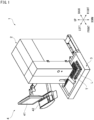
- FIG. 1 is a perspective view showing the appearance of an analyzer 1 according to the present embodiment.
- the analyzer 1 is a multi-item blood cell analyzer that counts blood cells, i.e., white blood cells contained in a blood specimen.
- the analyzer 1 includes: a measurement unit 2; a transport unit 3 disposed on the front side of the measurement unit 2; and an information processing unit 4.
- a blood specimen that is peripheral blood collected from a patient is contained in a specimen container (blood collection tube) T.
- a plurality of the specimen containers T are supported on a sample rack L.
- the sample rack L is transported by the transport unit 3, and each of the blood specimens is supplied to the measurement unit 2.
- the information processing unit 4 includes a display part 41 and an input part 42 and is communicably connected to the measurement unit 2, the transport unit 3, and a host computer 5 (see FIG. 2 ).
- the information processing unit 4 controls operations of the measurement unit 2 and the transport unit 3, performs analysis on the basis of the result of measurement performed by the measurement unit 2, and transmits the result of the analysis to the host computer 5 (see FIG. 2 ).
- FIG. 2 schematically illustrates an example of a configuration of the measurement unit 2.
- the measurement unit 2 includes a hand part 21, a specimen container setting part 22, a bar code unit 23, a specimen suction part 24, a sample preparation part 25, and a detector 26.
- the specimen suction part 24 includes a piercer 24a and suctions a specimen from each of the specimen containers T.
- the sample preparation part 25 includes a mixing chamber MC and a heater H.
- the sample preparation part 25 mixes a reagent with the specimen, to prepare a measurement sample that is used for measurement.
- the detector 26 includes an optical detector D and detects blood cells from the measurement sample.
- Each of the components of the measurement unit 2 is controlled by the information processing unit 4.
- Each specimen container T positioned at a position P1 by the transport unit 3 is gripped by the hand part 21 and pulled out upward from the sample rack L. Then, the hand part 21 is swung so that the specimen in the specimen container T is agitated. The specimen container T for which agitation has been finished is set, by the hand part 21, to the specimen container setting part 22 positioned at the position P1. Thereafter, the specimen container T is transported to a position P2 by the specimen container setting part 22.
- the bar code unit 23 disposed near the position P2 reads a specimen number from a bar code label pasted on the specimen container T. Thereafter, the specimen container T is transported to a position P3 by the specimen container setting part 22. When the specimen container T is positioned at the position P3, a predetermined amount of the specimen is suctioned from the specimen container T via the piercer 24a by the specimen suction part 24. When suction of the specimen is finished, the specimen container T is transported frontward by the specimen container setting part 22 and returned to the original support position on the sample rack L by the hand part 21. After the piercer 24a is transferred to a position in the mixing chamber MC, a predetermined amount of the specimen suctioned via the piercer 24a is discharged into the mixing chamber MC by the specimen suction part 24.
- the sample preparation part 25 mixes the blood specimen and a reagent with each other according to a predetermined preparation condition, to prepare a measurement sample.
- the reagent contains a hemolytic agent (first reagent) and a fluorescent substance (second reagent). Red blood cells and platelets in the blood are hemolyzed with the hemolytic agent, and white blood cells in the blood are stained with the fluorescent substance.
- the measurement sample prepared by the sample preparation part 25 is supplied to the optical detector D of the detector 26.
- FIG. 3 schematically illustrates an example of a configuration of the optical detector D.
- the optical detector D includes a flow cell D1, a sheath flow system D2, a beam spot forming system D3, a forward scattered light receiving system D4, a side scattered light receiving system D5, and a fluorescence receiving system D6.
- the sheath flow system D2 is configured to send the measurement sample into the flow cell D1 and generate a liquid flow in the flow cell D 1.
- the beam spot forming system D3 is configured such that light emitted from a semiconductor laser D31 passes through a collimator lens D32 and a condenser lens D33 and is applied to the flow cell D1. Thus, the laser light is applied to blood cells contained in the liquid flow passing through the inside of the flow cell D1.
- the beam spot forming system D3 further includes a beam stopper D34.
- the forward scattered light receiving system D4 is configured to condense scattered light advancing forward (forward scattered light) by a forward condenser lens D41 and receive light, which has passed through a pinhole D42, by a photodiode D43.
- the photodiode D43 outputs a forward scattered light signal (FSC) on the basis of a peak value of the received forward scattered light.
- the side scattered light receiving system D5 is configured to condense scattered light advancing sideways (side scattered light) by a side condenser lens D51, reflect a portion of the light by a dichroic mirror D52, and receive the portion by a photodiode D53.
- the photodiode D53 outputs a side scattered light signal (SSC) on the basis of a peak value of the received side scattered light.
- Light scattering is a phenomenon that occurs when the advancing direction of light is changed owing to the presence of a particle such as a blood cell as an obstacle in the advancing direction of the light. If the scattered light is detected, information about the size and the material properties of the particle can be obtained. In particular, information about the size of the particle (blood cell) can be obtained from forward scattered light. Further, information about the inside of the particle can be obtained from side scattered light. If laser light is applied to a blood cell particle, the intensity of the side scattered light is dependent on the complexity (the shape, the size, and the density of the nucleus and the amount of granules) inside the cell.
- the fluorescence receiving system D6 is configured to: allow a light (fluorescence), which has been transmitted through the dichroic mirror D52, of the side scattered light to further pass through a spectral filter D61; and receive the fluorescence by an avalanche photodiode D62.
- the avalanche photodiode D62 outputs a side fluorescence signal (SFL) on the basis of a peak value of the received fluorescence.
- the forward scattered light signal (FSC), the side scattered light signal (SSC), and the side fluorescence signal (SFL) obtained from each blood cell by the optical detector D are transmitted to the information processing unit 4.
- FIG. 4 illustrates an example of a configuration of the information processing unit 4.
- the information processing unit 4 is implemented by a personal computer and includes a body 40, the display part 41, and the input part 42.
- the body 40 includes a CPU 401, a ROM 402, a RAM 403, a hard disk 404, a read-out device 405, an image output interface 406, an input/output interface 407, and a communication interface 408.
- the CPU 401 executes a computer program stored in the ROM 402 and a computer program loaded to the RAM 403.
- the RAM 403 is used for reading out computer programs recorded in the ROM 402 and the hard disk 404.
- the RAM 403 is used also as a work area for the CPU 401 when these computer programs are executed.
- the hard disk 404 stores an operating system, a computer program to be executed by the CPU 401, and data used for executing the computer program.
- the hard disk 404 stores a program 404a for executing a process for the information processing unit 4.
- the read-out device 405 is implemented by a CD drive, a DVD drive, or the like, and can read out a computer program and data recorded in a non-transitory computer readable recording medium 405a. If the above program 404a is recorded in the recording medium 405a, the program 404a having been read out from the recording medium 405a by the read-out device 405 is stored in the hard disk 404.
- the image output interface 406 outputs, to the display part 41, a video signal corresponding to image data.
- the display part 41 displays an image on the basis of the video signal outputted from the image output interface 406.
- a user inputs an instruction through the input part 42.
- the input/output interface 407 receives a signal inputted through the input part 42.
- the communication interface 408 is connected to the measurement unit 2, the transport unit 3, and the host computer 5, and the CPU 401 transmits/receives an instruction signal and data to/from these devices via the communication interface 408.
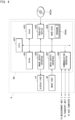
- FIG. 5 illustrates an example of a functional configuration of the information processing unit 4.
- a controller 500 is implemented through read-out and execution of a computer program by the CPU 401.
- a storage 505 is implemented by using the RAM 403 or the hard disk 404.
- the controller 500 includes: a measurement controller 501 configured to measure a specimen by controlling operations of the measurement unit 2 and the transport unit 3; an analysis processor 502 configured to, for example, classify white blood cells and count the number of blood cells on the basis of forward scattered light signals (FSC), side scattered light signals (SSC), and side fluorescence signals (SFL) measured by the detector 26 of the measurement unit 2; a display controller 503 configured to perform processing of displaying a measured number of blood cells in each type of white blood cell, a scattergram (distribution chart), etc., on the display part 41; and an input processor 504 configured to receive an input from the user through the input part 42.
- FSC forward scattered light signals
- SSC side scattered light signals
- SFL side fluorescence signals
- the storage 505 stores, for each blood cell, measurement information received from the measurement unit 2 and indicating the level of a forward scattered light signal (FSC), the level of a side scattered light signal (SSC), and the level of a side fluorescence signal (SFL).
- the measurement information expresses each of the level of the forward scattered light signal (FSC), the level of the side scattered light signal (SSC), and the level of the side fluorescence signal (SFL) by a quantized value called a "channel". The channel will be described later.
- the analysis processor 502 classifies, on the basis of the measurement information stored in the storage 505, white blood cells existing in the blood specimen into lymphocyte (LYMPH), monocyte (MONO), neutrophil (NEUT), basophil (BASO), and eosinophil (EO).
- the analysis processor 502 counts the number of blood cells in each of the classified types.
- the analysis processor 502 creates a scattergram (distribution chart) on the basis of the measurement information, to classify the white blood cells existing in the blood specimen.
- the scattergram is a two-dimensional distribution chart in which two types of signals out of the forward scattered light signal (FSC) outputted from the photodiode D43, the side scattered light signal (SSC) outputted from the photodiode D53, and the side fluorescence signal (SFL) outputted from the avalanche photodiode D62 are used as a vertical axis and a horizontal axis.
- FSC forward scattered light signal
- SSC side scattered light signal
- SFL side fluorescence signal
- the types of white blood cells that can be classified differ depending on the two types of signals to be used out of the forward scattered light signal (FSC), the side scattered light signal (SSC), and the side fluorescence signal (SFL).
- FSC forward scattered light signal
- SSC side scattered light signal
- SFL side fluorescence signal
- basophils and white blood cells other than basophils can be classified by using the forward scattered light signal (FSC) and the side fluorescence signal (SFL).
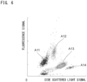
- the scattergram shown in FIG. 6 is an example of the case where dots corresponding to individual blood cells are plotted on a two-dimensional distribution chart in which the side scattered light signal (SSC) is used as a horizontal axis and the side fluorescence signal (SFL) is used as a vertical axis.
- the blood cells can be classified by the same method as the following method also in the case where basophils and white blood cells other than the basophils are classified by using the forward scattered light signal (FSC) and the side fluorescence signal (SFL) as two axes.
- FSC forward scattered light signal
- SFL side fluorescence signal
- the analysis processor 502 classifies each of the dots on the scattergram into any of four clusters corresponding to the four respective subclasses of white blood cells (a cluster A11 of lymphocytes, a cluster A12 of monocytes, a cluster A13 of neutrophils, and a cluster A14 of eosinophils). Specifically, for example, the belonging degrees of each of the blood cells to the clusters are obtained from the distances between a dot plotted on the scattergram and corresponding to the blood cell and the positions of preset centers of gravity of the clusters. Then, the blood cell is assigned to a corresponding cluster according to the belonging degrees.
- the information processing unit 4 obtains, on the basis of these digital signals, a scattergram in which i-channels are used for an X-axis and j-channels are used for a Y-axis as shown in FIG. 7 .
- each of the X-axis and the Y-axis has 256 channels.
- the scattergram is composed of a total of 256 ⁇ 256 basic elements indicating the states of blood cells.
- Each of the basic elements stores the number of blood cells corresponding to the basic element.
- the value of a basic element at channel 1 in the X-axis and channel 2 in the Y-axis indicates that there are six blood cells for each of which: the intensity of a signal indicating the size of the cytoplasm of the blood cell is 1; and the intensity of a composite signal indicating the densities and the sizes of the nucleus and granules of the blood cell is 2.
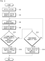
- FIG. 8 is a flowchart showing an example of processing of assigning each blood cell to any of the clusters.
- the information processing unit 4 performs initial division (S2). The initial division is performed as follows while the number of blood cells in each of the basic elements of the scattergram shown in FIG. 7 is ignored.
- S2 initial division
- the initial division is performed as follows while the number of blood cells in each of the basic elements of the scattergram shown in FIG. 7 is ignored.
- lymphocytes the distribution of the basic elements is divided by a fixed region in which the lymphocytes are assumed to be obviously distributed.
- monocytes the distribution of the basic elements is divided by a fixed region in which the monocytes are assumed to be obviously distributed.
- neutrophils the distribution of the basic elements is divided by a fixed region in which the neutrophils are assumed to be obviously distributed.
- the distribution of the basic elements is divided by a fixed region in which the eosinophils are assumed to be obviously distributed.
- the distribution of the basic elements is divided by a fixed region in which the ghosts are assumed to be obviously distributed.
- Each of the fixed regions is preset.
- the belonging degree of each of the blood cells existing in a corresponding fixed region is defined as 1.
- the information processing unit 4 calculates an initial center of gravity of the cluster of lymphocytes by using the following Mathematical expression 1 and Mathematical expression 2 (S4).
- X G 1 ⁇ i ⁇ j Nij ⁇ i / ⁇ i ⁇ j Nij
- Y G 1 ⁇ i ⁇ j Nij ⁇ i / ⁇ i ⁇ j Nij
- N ij is the number of blood cells at a basic element i, j.
- the positions of centers of gravity are obtained in the same manner as for the clusters of monocytes, neutrophils, eosinophils, and ghosts.
- the information processing unit 4 calculates the belonging degrees, to the clusters, of each of blood cells that do not belong to any of the fixed regions (S6). More specifically, the information processing unit 4 calculates the belonging degrees to the clusters on the basis of the distances from the position of each of the blood cells to the positions of the centers of gravity of the clusters.
- the distance from the position of the blood cell to each of the positions of the centers of gravity of the clusters is not the distance (Euclidean distance) between the position of the blood cell and the position of the cluster, but the length of the minor axis of a predetermined ellipse is defined as the distance between the position of the blood cell and the position of the cluster.
- the predetermined ellipse refers to an ellipse that has a center at the position of the center of gravity of a cluster and that has a specific tilt having been set in advance according to the cluster.
- a given blood cell is positioned on the arc of the ellipse. If the minor axis of the ellipse is defined as "a”, the major axis thereof is represented by "ak” ("k" is a coefficient of proportionality).
- the information processing unit 4 calculates the belonging degrees, to the clusters, of each blood cell that does not belong to any of the fixed regions.
- the belonging degree of each blood cell to the cluster is used as a weight to calculate a weighted center of gravity (S8).
- the weighted center of gravity is obtained according to, for example, Mathematical expression 4 and Mathematical expression 5.
- X G 1 ′ ⁇ i ⁇ j Uij ⁇ Nij ⁇ i / ⁇ i ⁇ j Uij ⁇ Nij
- Y G 1 ′ ⁇ i ⁇ j Uij ⁇ Nij ⁇ j / ⁇ i ⁇ j Uij ⁇ Nij
- U ij represents the belonging degree of a blood cell at a basic element i, j to a certain cluster G1.
- the weighted center of gravity of each cluster is obtained in this manner, the weighted center of gravity is compared with a corresponding one of the positions of the initial centers of gravity of the clusters obtained in step S4, and whether the change amount therebetween is a predetermined amount, e.g. 0, is determined (S10). If the change amount is not the predetermined amount, the position of the presently-obtained weighted center of gravity of the cluster is used in place of the initial center of gravity of the cluster, and the processing procedures of steps S6, S8, and S10 are repeated.
- a predetermined amount e.g. 0
- the distances from the position of each blood cell to the positions of the weighted centers of gravity of the clusters are obtained; the belonging degrees of the blood cell to the clusters are obtained on the basis of the distances; the positions of weighted centers of gravity of the clusters are newly obtained on the basis of the belonging degrees; and whether the change amount between each of the positions of the new weighted centers of gravity of the clusters and the position of the previous weighted center of gravity of the cluster is the predetermined amount, is determined. If the change amount is not the predetermined amount again, the position of the presently-obtained weighted center of gravity of the cluster is set as the position of an initial center of gravity thereof, and the processing procedures of steps S6, S8, and S10 are repeated.
- step S10 determines whether the number of times of execution of steps S6, S8, and S10 is the predetermined number of times (S12). If the number reaches the predetermined number of times, the information processing unit 4 displays, on the display part 41, an indication that analysis is impossible (S14), and ends the processing.
- the information processing unit 4 determines final belonging of each blood cell to a corresponding cluster, to determine the number of blood cells in each cluster (step S16).
- the blood cell may be regarded as belonging to a cluster in which the blood cell has a maximum value out of the finally obtained belonging degrees.
- the belonging degree of each of these blood cells to the cluster of lymphocytes is 0.95
- the belonging degree thereof to the cluster of monocytes is 0.03
- the belonging degree thereof to the cluster of neutrophils is 0.03
- the belonging degree thereof to the cluster of eosinophils is 0.02
- the belonging degree thereof to the cluster of ghosts is 0, all of these ten blood cells are regarded as belonging to the cluster of lymphocytes in which the blood cells have the maximum belonging degree.
- each blood cell existing in the scattergram is assigned to any of the clusters.
- the analyzer 1 first performs processing of classifying white blood cells and counting the number of blood cells with use of a measurement sample prepared according to a predetermined preparation condition; and outputting an analysis result. This processing is referred to as a "normal mode" in the present embodiment. If the analyzer 1 determines that the white blood cells may not have been sufficiently classified in the normal mode, the analyzer 1 performs processing of preparing a measurement sample under a different preparation condition; classifying white blood cells and counting the number of blood cells again; and outputting an analysis result. This processing is referred to as an "extension mode" in the present embodiment.
- FIG. 9 is a flowchart showing an example of processing procedures to be executed by the analyzer 1.
- step S100 the sample preparation part 25 of the measurement unit 2 mixes a blood specimen and a reagent with each other according to a predetermined preparation condition, to prepare a measurement sample.
- a predetermined preparation condition is referred to as "preparation condition A”.
- Preparation condition A is a condition regarding a time length during which the reagent is reacted with the blood specimen.
- Preparation condition A (the same applies to preparation condition B described below) may be at least either one condition among a condition regarding the temperature when the reagent is reacted with the blood specimen and a condition regarding the mixing ratio between the blood specimen and the reagent.
- the condition regarding the time length during which the reagent is reacted with the blood specimen may be a condition regarding a time length of heating when the blood specimen and the reagent are blended and heated by a heater.
- the reaction time, the temperature, and the mixing ratio in preparation condition A are set in advance to a value that allows white blood cells to be classified into lymphocytes, monocytes, neutrophils, basophils, and eosinophils in the case of a healthy blood specimen.
- the detector 26 of the measurement unit 2 applies light (laser light) to the prepared measurement sample, to obtain light signals.
- the controller 500 of the information processing unit 4 classifies white blood cells contained in the blood specimen on the basis of the light signals and counts the number of blood cells in each type of white blood cell.
- step S101 the controller 500 of the information processing unit 4 outputs a scattergram and/or the number of blood cells in each type of white blood cell as the result of classification of the white blood cells.
- step S 102 the controller 500 evaluates, for the measurement sample prepared according to preparation condition A, classification performance regarding classification of white blood cells (cell classification), to determine whether or not the white blood cells have been sufficiently separated.
- classification performance means an index indicating the extent of accuracy with which a plurality of types of cells have been classified. More specifically, the classification performance means an index indicating that the blood specimen has been accurately classified into the types of white blood cells (lymphocytes, monocytes, neutrophils, basophils, and eosinophils) by analyzing the light signals.
- the controller 500 determines that the white blood cells have not been sufficiently classified.
- the controller 500 determines that the white blood cells have been sufficiently classified (may be rephrased as "if the classification performance does not satisfy a predetermined condition"), the controller 500 ends the processing without performing transition to the extension mode. Meanwhile, if the controller 500 determines that the white blood cells may not have been sufficiently classified (may be rephrased as "if the classification performance satisfies the predetermined condition"), the controller 500 proceeds to the processing procedure of step S103 in order to perform transition to the extension mode.
- the case where the white blood cells may not have been sufficiently classified is considered to occur if, for example, an unhealthy blood specimen such as blood collected from a subject who suffers from a certain disease is analyzed.
- step S 103 the sample preparation part 25 of the measurement unit 2 mixes the blood specimen and the reagent with each other according to preparation condition A again, to prepare a measurement sample. Subsequently, the detector 26 of the measurement unit 2 applies light to the prepared measurement sample, to obtain light signals. Subsequently, the controller 500 of the information processing unit 4 classifies white blood cells contained in the blood specimen by using the light signals and counts the number of blood cells in each type of white blood cell.
- step S 104 the sample preparation part 25 of the measurement unit 2 mixes the blood specimen and the reagent with each other according to preparation condition B different from preparation condition A, to prepare a measurement sample. Subsequently, the detector 26 of the measurement unit 2 applies light to the prepared measurement sample, to obtain light signals. Subsequently, the controller 500 of the information processing unit 4 classifies white blood cells contained in the blood specimen by using the light signals and counts the number of blood cells in each type of white blood cell.
- step S105 the controller 500 compares the result of the classification of the white blood cells performed by using the light signals obtained under preparation condition A and the result of the classification of the white blood cells performed by using the light signals obtained under preparation condition B. If the result of the comparison between the result of the classification under preparation condition A and the result of the classification under preparation condition B is within a predetermined range, the controller 500 determines that the white blood cells have been sufficiently classified under preparation condition A, and proceeds to the processing procedure of step S106. Meanwhile, if the result of the comparison is outside the predetermined range, the controller 500 determines that the white blood cells have been more appropriately classified in the result of the classification under preparation condition B than in the result of the classification under preparation condition A, and proceeds to the processing procedure of step S107.
- step S106 the controller 500 outputs an analysis result including the number of blood cells in each type of white blood cell on the basis of the result of the comparison in step S 105. More specifically, the controller 500 outputs the counted number of each type of white blood cell and/or a scattergram that are based on the light signals obtained under preparation condition A.
- step S107 the controller 500 outputs an analysis result including the number of blood cells in each type of white blood cell on the basis of the result of the comparison in step S105.
- the controller 500 outputs, to the display part 41, the counted number of each type of white blood cell and/or a scattergram that are based on the light signals obtained under preparation condition A and information about the reliability of the counted number of each type of white blood cell.
- the information about the reliability may be, for example, a flag or a character string indicating that the counted number of each type of white blood cell and/or the scattergram has low reliability.
- the controller 500 classifies white blood cells by using two light signals, i.e., the side fluorescence signal (SFL) and the side scattered light signal (SSC) which are emitted from measurement sample A (or measurement sample B).
- White blood cells may be classified by using at least two light signals among two types of scattered lights (that is, the forward scattered light signal (FSC) and the side scattered light signal (SSC)) each having a different angle, and the side fluorescence signal (SFL).
- the controller 500 obtains the result of classification of white blood cells on the basis of a scattergram obtained by plotting, in different axes, two light signals, i.e., the side fluorescence signal (SFL) and the side scattered light signal (SSC).
- SFL side fluorescence signal
- SSC side scattered light signal
- the controller 500 obtains, by using the side fluorescence signal (SFL) and the side scattered light signal (SSC), a classification result in which the blood specimen is classified into four types, i.e., lymphocyte, monocyte, neutrophil, and eosinophil.
- SFL side fluorescence signal
- SSC side scattered light signal
- the controller 500 may obtain, by using all of the forward scattered light signal (FSC), the side scattered light signal (SSC), and the side fluorescence signal (SFL), a classification result in which the blood specimen is classified into five types, i.e., lymphocyte, monocyte, neutrophil, basophil, and eosinophil.
- FSC forward scattered light signal
- SSC side scattered light signal
- SFL side fluorescence signal
- Preparation condition A, the measurement sample, and the light signals in the processing procedure of step S103 described above are referred to as a first preparation condition, a first measurement sample, and first light signals, respectively.
- preparation condition B, the measurement sample, and the light signals in the processing procedure of step S104 are referred to as a second preparation condition, a second measurement sample, and second light signals, respectively.
- preparation condition A, the measurement sample, and the light signals in the processing procedure of step S100 are referred to as a third preparation condition, a third measurement sample, and third light signals, respectively.
- preparation condition A, the measurement sample, and the light signals in the processing procedure of step S100 are referred to as the first preparation condition, the first measurement sample, and the first light signals, respectively.
- preparation condition B, the measurement sample, and the light signals in the processing procedure of step S104 are referred to as the second preparation condition, the second measurement sample, and the second light signals, respectively.
- step S100 and step S103 preparation of a sample under preparation condition A, light signal measurement, and classification, are executed in step S100 and step S103. Consequently, even if a long time elapses from the sample preparation in step S100 until the sample preparation in step S103, the sample preparation under preparation condition A is performed by using a sample in a state that is similar to the state of a sample to be prepared according to preparation condition B in step S104. Therefore, the accuracy of the analysis result to be outputted in step S106 or step S107 can be improved.
- the controller 500 outputs, in the processing procedure of step S107, the counted number of each type of white blood cell and/or a scattergram that are based on the light signals obtained under preparation condition B.
- the controller 500 may not perform the processing procedures of step S103 and step S105 out of the processing procedures shown in FIG. 9 . That is, if an evaluation result obtained by evaluating the classification performance for white blood cells for which the light signals obtained under preparation condition A have been used satisfies the predetermined condition, the controller 500 executes the processing procedure of step S104 without executing the processing procedure of step S103. Further, the controller 500 classifies white blood cells contained in the blood specimen by using the light signals that have been obtained under preparation condition B and that have been obtained in the processing procedure of step S104, counts the number of each type of blood cells, and outputs the counted number of each type of white blood cell and/or a scattergram to the display part 41.
- preparation condition A, the measurement sample, and the light signals in the processing procedure of step S100 are referred to as the first preparation condition, the first measurement sample, and the first light signals, respectively.
- preparation condition B, the measurement sample, and the light signals in the processing procedure of step S104 are referred to as the second preparation condition, the second measurement sample, and the second light signals, respectively.
- the controller 500 receives a measurement instruction, to measure the blood specimen not in the normal mode but in the extension mode, from a user through the input part 42. In this case, when the controller 500 receives the measurement instruction, the controller 500 does not perform the processing procedures of step S100 to step S102 out of the processing procedures shown in FIG. 9 (that is, the normal mode is not used).
- the controller 500 performs processing in which modification 1 and modification 3 described above are combined with each other. That is, if the controller 500 receives, from the user, the measurement instruction to measure the blood specimen not in the normal mode but in the extension mode, the controller 500 does not perform the processing procedures of step S100 to step S102 out of the processing procedures shown in FIG. 9 (that is, the normal mode is not used). In addition, in the processing procedure of step S107, the counted number of each type of white blood cell and/or a scattergram that are based on the light signals obtained under preparation condition B is outputted.
- Preparation condition B is a condition in which the time during which the reagent is reacted with the blood specimen is set to be longer than that in preparation condition A.
- preparation condition B may be a condition in which the temperature when the reagent is reacted with the blood specimen is set to be higher than that in preparation condition A.
- preparation condition B may be a condition in which, regarding the mixing ratio between the blood specimen and the reagent, the proportion of the reagent is set to be higher than that in preparation condition A.
- processing of determining whether or not the white blood cells have been sufficiently classified (S 102) in processing of determining whether or not to perform transition from the normal mode to the extension mode; and processing of outputting, in the extension mode, an analysis result through comparison between the result of classification of white blood cells under preparation condition A and the result of classification of white blood cells under preparation condition B (S105 to S107).
- Pattern A is a method in which the number of cells belonging to one cluster among a plurality of clusters existing in a scattergram is used to perform determination or comparison for the results of classification of white blood cells.
- the controller 500 determines that the white blood cells may not have been sufficiently classified (that is, determines that the classification performance satisfies the predetermined condition). Meanwhile, if the counted numbers of all types of white blood cells are values other than the predetermined value (for example, 0) or are equal to or larger than the predetermined value, the controller 500 determines that the white blood cells have been sufficiently classified (that is, determines that the classification performance does not satisfy the predetermined condition).
- the controller 500 determines that the white blood cells have not been sufficiently classified.
- the controller 500 outputs an analysis result including the number of blood cells in each type of white blood cell on the basis of the result of the comparison between the number of cells belonging to one cluster among a plurality of clusters included in a scattergram obtained under preparation condition A and the number of cells belonging to the one cluster among a plurality of clusters included in a scattergram obtained under preparation condition B.
- the controller 500 determines that the white blood cells have been sufficiently classified under preparation condition A, and proceeds to the processing procedure of step S106. Meanwhile, if this difference is outside the predetermined range, the controller 500 determines that the white blood cells have been more appropriately classified in the result of the classification under preparation condition B than in the result of the classification under preparation condition A, and proceeds to the processing procedure of step S107.
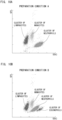
- FIG. 10A illustrates an example of the result of the classification under preparation condition A
- FIG. 10B illustrates an example of the result of the classification under preparation condition B.
- no cluster of eosinophils exists (the number of eosinophils is 0) in the result of the classification under preparation condition A
- a cluster of eosinophils exists (the number of eosinophils is equal to or larger than 100) in the result of the classification under preparation condition B. Therefore, the controller 500 determines that the white blood cells have been more appropriately classified in the result of the classification under preparation condition B than in the result of the classification under preparation condition A.
- Pattern B is a method in which the number of clusters existing in a scattergram is used to perform determination or comparison for the results of classification of white blood cells.
- the controller 500 determines that the white blood cells may not have been sufficiently classified (that is, determines that the classification performance satisfies the predetermined condition). Meanwhile, if the number of clusters is the predetermined value, the controller 500 determines that the white blood cells have been sufficiently classified (that is, determines that the classification performance does not satisfy the predetermined condition).
- the predetermined value is set in advance according to the type of the scattergram.
- the predetermined value is four types (neutrophil, lymphocyte, monocyte, and eosinophil).
- the controller 500 outputs an analysis result including the number of blood cells in each type of white blood cell on the basis of the result of the comparison between the number of clusters existing in a scattergram obtained under preparation condition A and the number of clusters existing in a scattergram obtained under preparation condition B.
- the controller 500 determines that the white blood cells have been sufficiently classified under preparation condition A, and proceeds to the processing procedure of step S106. Meanwhile, if this difference is outside the predetermined range (for example, the difference is equal to or larger than 1), the controller 500 determines that the white blood cells have been more appropriately classified in the result of the classification under preparation condition B than in the result of the classification under preparation condition A, and proceeds to the processing procedure of step S107.
- a predetermined range for example, the difference is 0
- the controller 500 determines that the white blood cells have been sufficiently classified under preparation condition A, and proceeds to the processing procedure of step S106. Meanwhile, if this difference is outside the predetermined range (for example, the difference is equal to or larger than 1), the controller 500 determines that the white blood cells have been more appropriately classified in the result of the classification under preparation condition B than in the result of the classification under preparation condition A, and proceeds to the processing procedure of step S107.
- the controller 500 determines that the white blood cells have been more appropriately classified in the result of the classification under preparation condition B than in the result of the classification under preparation condition A.
- Pattern C is a method in which the distance between two clusters included in a scattergram is used to perform determination or comparison for the results of classification of white blood cells.
- the controller 500 determines that the white blood cells may not have been sufficiently classified (that is, determines that the classification performance satisfies the predetermined condition). Meanwhile, if the distance between the two clusters is larger than the predetermined value, the controller 500 determines that the white blood cells have been sufficiently classified (that is, determines that the classification performance does not satisfy the predetermined condition).
- the controller 500 determines that the white blood cells have not been sufficiently classified.
- the controller 500 outputs an analysis result including the number of blood cells in each type of white blood cell on the basis of the result of the comparison between the distance between two clusters included in a scattergram obtained under preparation condition A and the distance between the two clusters included in a scattergram obtained under preparation condition B.
- the controller 500 determines that the white blood cells have been sufficiently classified under preparation condition A, and proceeds to the processing procedure of step S106. Meanwhile, if this difference is outside the predetermined range (for example, in the case of being longer than 10 channels, or the like), the controller 500 determines that the white blood cells have been more appropriately classified in the result of the classification under preparation condition B than in the result of the classification under preparation condition A, and proceeds to the processing procedure of step S107.
- a predetermined range for example, equal to or shorter than 10 channels or the like
- the distance between a cluster of neutrophils and a cluster of eosinophils is 25 channels in the result of the classification under preparation condition A, but the distance between the cluster of neutrophils and the cluster of eosinophils is 50 channels in the result of the classification under preparation condition B.
- the difference between the distances between the clusters is 25 channels and outside the predetermined range (10 channels). Therefore, the controller 500 determines that the white blood cells have been more appropriately classified in the result of the classification under preparation condition B than in the result of the classification under preparation condition A.
- the distance between clusters may be obtained by comparing the average values, in the X-axis, of the positions of blood cells belonging to the clusters, with each other.
- the distance between clusters is not limited thereto and may be obtained by comparing the average values, in the Y-axis, of the positions of blood cells belonging to the clusters, with each other.
- the two clusters may be set in advance according to the type of the scattergram.
- the distances between a cluster of lymphocytes and a cluster of monocytes may be set to be compared with each other
- the distances between the cluster of monocytes and a cluster of neutrophils may be set to be compared with each other
- the distances between the cluster of neutrophils and a cluster of eosinophils may be set to be compared with each other.
- Pattern D is a method in which the extent to which the boundaries of two clusters existing in a scattergram are in contact with each other is used to perform determination or comparison for the results of classification of white blood cells.
- the controller 500 determines that the white blood cells may not have been sufficiently classified (that is, determines that the classification performance satisfies the predetermined condition). Meanwhile, if the extent to which the boundaries of the two clusters are in contact with each other is larger than the predetermined value, the controller 500 determines that the white blood cells have been sufficiently classified (that is, determines that the classification performance does not satisfy the predetermined condition).
- the controller 500 outputs an analysis result including the number of blood cells in each type of white blood cell on the basis of the result of the comparison between the extent to which the boundaries of two clusters included in a scattergram obtained under preparation condition A are in contact with each other and the extent to which the boundaries of the two clusters included in a scattergram obtained under preparation condition B are in contact with each other.
- the controller 500 determines that the white blood cells have been sufficiently classified under preparation condition A, and proceeds to the processing procedure of step S106. Meanwhile, if this difference is outside the predetermined range, the controller 500 determines that the white blood cells have been more appropriately classified in the result of the classification under preparation condition B than in the result of the classification under preparation condition A, and proceeds to the processing procedure of step S107.
- FIG. 12A illustrates an example of the result of the classification under preparation condition A
- FIG. 12B illustrates an example of the result of the classification under preparation condition B
- a cluster of neutrophils and a cluster of eosinophils are in contact with each other in the result of the classification under preparation condition A, but the cluster of neutrophils and the cluster of eosinophils are not in contact with each other in the result of the classification under preparation condition B. Therefore, the controller 500 determines that the white blood cells have been more appropriately classified in the result of the classification under preparation condition B than in the result of the classification under preparation condition A.
- FIG. 13A illustrates an example of calculation of the extent to which the boundaries of two clusters are in contact with each other.
- FIG. 13B illustrates an example of the calculation of the extent to which the boundaries of the two clusters are in contact with each other.
- FIG. 13A and FIG. 13B are enlarged diagrams of areas in which the cluster of neutrophils and the cluster of eosinophils are in contact with each other in the scattergrams.
- the vertical direction is an axis (Y-axis) based on the side fluorescence signal (SFL), and the horizontal direction is an axis (X-axis) based on the side scattered light signal (SSC).
- the extent to which the boundaries of two clusters are in contact with each other is a value obtained by counting the number of coordinates, among coordinates existing around each coordinate on the boundary of either one cluster out of the two clusters, at which blood cells belonging to the other cluster exist.
- the coordinate at which neutrophils exist is one coordinate on the upper left side of the coordinate of A4.
- the coordinates at which neutrophils exist are three coordinates on the left, upper left, and upper sides of the coordinate of A8.
- the extent to which the boundaries of the cluster of neutrophils and the cluster of eosinophils are in contact with each other is "9".
- the extent to which the boundaries of the cluster of neutrophils and the cluster of eosinophils are in contact with each other is "1".
- the number of coordinates may be counted on the basis of the cluster of neutrophils. For example, the number of coordinates at which eosinophils exist among coordinates existing around each coordinate on the boundary of the cluster of neutrophils, is counted.
- the two clusters, the contact extents of which are to be compared with each other may be set in advance according to the type of the scattergram.
- the extents to which a cluster of lymphocytes and a cluster of monocytes are in contact with each other may be compared with each other
- the extents to which the cluster of monocytes and a cluster of neutrophils are in contact with each other may be compared with each other
- the extents to which the cluster of neutrophils and a cluster of eosinophils are in contact with each other may be compared with each other.
- Pattern E is a method in which the distribution shape of blood cells of a cluster existing in a scattergram is used to perform determination or comparison for the results of classification of white blood cells.
- the controller 500 determines that the white blood cells may not have been sufficiently classified (that is, determines that the classification performance satisfies the predetermined condition). Meanwhile, if the distribution shape of the blood cells, in the X-axis or the Y-axis, of the at least one cluster existing in the scattergram does not satisfy the predetermined condition, the controller 500 determines that the white blood cells have been sufficiently classified (that is, determines that the classification performance does not satisfy the predetermined condition).
- the predetermined condition may be that two or more peaks exist when the numbers of blood cells existing in respective channels in the X-axis are represented by a histogram.
- the method for calculating the numbers of the blood cells existing in the respective channels in the X-axis will be described with reference to FIG. 7 .
- the controller 500 outputs an analysis result including the number of blood cells in each type of white blood cell on the basis of the result of the comparison between the distribution shape of blood cells, in the X-axis or the Y-axis, of a predetermined cluster existing in a scattergram obtained under preparation condition A and the distribution shape of blood cells, in the X-axis or the Y-axis, of the predetermined cluster existing in a scattergram obtained under preparation condition B.
- the controller 500 determines that the white blood cells have been sufficiently classified under preparation condition A, and proceeds to the processing procedure of step S106.
- the controller 500 determines that the white blood cells have been more appropriately classified in the result of the classification under preparation condition B than in the result of the classification under preparation condition A, and proceeds to the processing procedure of step S107.
- the predetermined cluster used for determining the number of peaks may be any of a cluster of lymphocytes, a cluster of monocytes, a cluster of neutrophils, a cluster of eosinophils, and a cluster of basophils.
- one cluster for example, a cluster of neutrophils may be set in advance.
- FIG. 14A illustrates an example of the result of the classification under preparation condition A
- FIG. 14B illustrates an example of the result of the classification under preparation condition B
- two peaks exist in a cluster of neutrophils in the case of preparation condition A, but only one peak exists in the cluster of neutrophils in the case of preparation condition B.
- the number of clusters under preparation condition A is three, but the number of clusters under preparation condition B is four. Therefore, the controller 500 determines that the white blood cells have been more appropriately classified in the result of the classification under preparation condition B than in the result of the classification under preparation condition A.
- Pattern F is a method in which the number of clusters existing in a scattergram and the number of boundary particles are used to perform determination or comparison for the results of classification of white blood cells.
- the controller 500 outputs an analysis result including the number of blood cells in each type of white blood cell on the basis of the result of the comparison between: the number of clusters existing in a scattergram obtained under preparation condition A and the number of boundary particles in a predetermined one of the clusters; and the number of clusters existing in a scattergram obtained under preparation condition B and the number of boundary particles in the predetermined cluster.
- the controller 500 determines that the white blood cells have been sufficiently classified under preparation condition A, and proceeds to the processing procedure of step S106.
- the controller 500 determines that the white blood cells have been more appropriately classified in the result of the classification under preparation condition B than in the result of the classification under preparation condition A, and proceeds to the processing procedure of step S107.
- the number of boundary particles in a predetermined cluster means the number of blood cells that exist on a boundary portion in the predetermined cluster and that are of a type different from that of the predetermined cluster.
- SFL side fluorescence signal
- SSC side scattered light signal
- the counted number of the blood cells that can be classified as eosinophils corresponds to "the number of boundary particles in the predetermined cluster”.
- Pattern G is a method in which the width of a predetermined cluster and the number of clusters existing in a scattergram are used to perform determination or comparison for the results of classification of white blood cells.
- the controller 500 outputs an analysis result including the number of blood cells in each type of white blood cell on the basis of the result of the comparison between: the width of a predetermined cluster and the number of clusters existing in a scattergram obtained under preparation condition A; and the width of the predetermined cluster and the number of clusters existing in a scattergram obtained under preparation condition B.
- the controller 500 determines that the white blood cells have been sufficiently classified under preparation condition A, and proceeds to the processing procedure of step S106.
- the controller 500 determines that the white blood cells have been more appropriately classified in the result of the classification under preparation condition B than in the result of the classification under preparation condition A, and proceeds to the processing procedure of step S107.
- FIG. 16A illustrates an example of the result of the classification under preparation condition A
- FIG. 16B illustrates an example of the result of the classification under preparation condition B
- the width of a cluster of neutrophils under preparation condition A is 50 channels
- the width of the cluster of neutrophils under preparation condition B is 40 channels
- the number of clusters under preparation condition A is three, but the number of clusters under preparation condition B is four. Therefore, the controller 500 determines that the white blood cells have been more appropriately classified in the result of the classification under preparation condition B than in the result of the classification under preparation condition A.
- the width of the cluster may be a width in the X-axis or a width in the Y-axis.
- the width of the cluster may be a width, in the X-axis (or Y-axis), that includes channels in each of which the number of blood cells existing in the channel is equal to or larger than a predetermined number.
- the scattergram under preparation condition A and the scattergram under preparation condition B described above are referred to as a first distribution chart and a second distribution chart, respectively.
- the result of the classification of white blood cells performed by using light signals obtained under preparation condition A may be expressed as at least one of "the number of white blood cells belonging to one cluster among a plurality of clusters included in a scattergram under preparation condition A", “the number of a plurality of clusters included in a scattergram under preparation condition A”, “the distance between two clusters included in a scattergram under preparation condition A”, “the extent to which the boundaries of two clusters included in a scattergram under preparation condition A are in contact with each other", and "the width of a predetermined cluster among a plurality of clusters included in a scattergram under preparation condition A".
- the result of the classification of white blood cells performed by using light signals obtained under preparation condition B may be expressed as at least one of "the number of white blood cells belonging to one cluster among a plurality of clusters included in a scattergram under preparation condition B", “the number of a plurality of clusters included in a scattergram under preparation condition B", “the distance between two clusters included in a scattergram under preparation condition B”, “the extent to which the boundaries of two clusters included in a scattergram under preparation condition B are in contact with each other", and "the width of a predetermined cluster among a plurality of clusters included in a scattergram under preparation condition B".
- the result of the comparison between the result of the classification under preparation condition A and the result of the classification under preparation condition B may be expressed as at least one of "the result of the comparison between the number of white blood cells belonging to the one cluster among the plurality of clusters included in the scattergram under preparation condition A and the number of white blood cells belonging to the one cluster among the plurality of clusters included in the scattergram under preparation condition B", "the result of the comparison between the number of the plurality of clusters included in the scattergram under preparation condition A and the number of the plurality of clusters included in the scattergram under preparation condition B", “the result of the comparison between the distance between the two clusters included in the scattergram under preparation condition A and the distance between the two clusters included in the scattergram under preparation condition B", "the result of the comparison between the extent to which the boundaries of the two clusters included in the scattergram under preparation condition A are in contact with each other and the extent to which the boundaries of the two clusters included in the scattergram under preparation condition B are in contact with each other", and "the result of the comparison between the extent to
- a blood specimen having been subjected to preparation on the basis of preparation condition A is measured in the normal mode. If determination that white blood cells may not have been sufficiently classified in the normal mode is made, transition is made to the extension mode in which classification of white blood cells is performed on both of the blood specimen having been subjected to preparation on the basis of preparation condition A and the blood specimen having been subjected to preparation on the basis of preparation condition B. In addition, both results of classification are compared with each other, and an analysis result including the result of the comparison is outputted. This makes it possible to inhibit an analysis result with an insufficient accuracy from being outputted depending on the property of the specimen.
- the present disclosure is not limited to the example.
- the present disclosure may be applied to an example in which neutrophils and monocytes are classified by using the side fluorescence signal (SFL) and the side scattered light signal (SSC).
- the reaction time for a specimen and a reagent under the preparation condition in step S104 shown in FIG. 9 may be set to be shorter than the reaction time for the specimen and the reagent under the preparation condition in step S103 shown in FIG. 9 .
- reaction temperature under the preparation condition in step S104 may be set to be lower than the reaction temperature under the preparation condition in step S103, or the mixing ratio of the reagent under the preparation condition in step S104 may be set to be lower than the mixing ratio of the reagent under the preparation condition in step S103.
- the types of light signals used for classifying blood cells are not limited, and two types other than the above-described combinations may be combined with each other. Alternatively, three or more types of light signals may be combined with one another. Alternatively, one type of light signal may be used.
- the type of cells to be classified under the two types of preparation conditions is also not limited to white blood cells and may be red blood cells, platelets, or other blood cells.
- an analyzer 1 for analyzing urine may be configured to classify red blood cells, white blood cells, epithelial cells, squamous epithelial cells, casts, and bacteria contained in urine and count the number of each of the classified types.
- the above-described embodiment is not limited to a mode in which: light is applied to a first measurement sample and a second measurement sample; and light signals are obtained.
- the present disclosure may be applied to a cell analyzer configured to: obtain electrical signals generated when the first measurement sample and the second measurement sample pass through a small hole to which voltage has been applied; and classify cells by using the obtained electrical signals.
- the "first light signal” may be referred to as a "first signal”
- the "second light signal” may be referred to as a "second signal”
- the "third light signal” may be referred to as a "third signal”.
Landscapes
- Physics & Mathematics (AREA)
- Health & Medical Sciences (AREA)
- Life Sciences & Earth Sciences (AREA)
- Chemical & Material Sciences (AREA)
- General Health & Medical Sciences (AREA)
- Engineering & Computer Science (AREA)
- Biochemistry (AREA)
- Analytical Chemistry (AREA)
- General Physics & Mathematics (AREA)
- Immunology (AREA)
- Pathology (AREA)
- Bioinformatics & Cheminformatics (AREA)
- Dispersion Chemistry (AREA)
- Theoretical Computer Science (AREA)
- Spectroscopy & Molecular Physics (AREA)
- Biophysics (AREA)
- Bioinformatics & Computational Biology (AREA)
- Biotechnology (AREA)
- Evolutionary Biology (AREA)
- Medical Informatics (AREA)
- Bioethics (AREA)
- Physiology (AREA)
- Molecular Biology (AREA)
- Databases & Information Systems (AREA)
- Signal Processing (AREA)
- Investigating Or Analysing Biological Materials (AREA)
- Apparatus Associated With Microorganisms And Enzymes (AREA)
- Measuring Or Testing Involving Enzymes Or Micro-Organisms (AREA)
- Investigating, Analyzing Materials By Fluorescence Or Luminescence (AREA)
- Computer Vision & Pattern Recognition (AREA)
Claims (14)
- Zellklassifizierungsverfahren, das von einem Analysegerät auszuführen ist, um in einer Probe enthaltene Zellen zu klassifizieren, wobei das Zellklassifizierungsverfahren umfasst:Vorbereiten einer ersten Messprobe durch Mischen einer Probe und eines Reagens unter einer ersten Präparationsbedingung (S103);Erhalten eines ersten Signals aus der vorbereiteten ersten Messprobe;Klassifizieren der in der ersten Messprobe enthaltenen Zellen unter Verwendung des ersten Signals;Vorbereiten einer zweiten Messprobe durch Mischen der Probe und des Reagens unter einer zweiten Präparationsbedingung, die sich von der ersten Präparationsbedingung unterscheidet (S104);Erhalten eines zweiten Signals aus der vorbereiteten zweiten Messprobe;Klassifizieren der in der zweiten Messprobe enthaltenen Zellen unter Verwendung des zweiten Signals;Vergleichen (S105) eines Ergebnisses der unter Verwendung des ersten Signals durchgeführten Zellklassifizierung und eines Ergebnisses der unter Verwendung des zweiten Signals durchgeführten Zellklassifizierung miteinander, undAusgeben eines Analyseergebnisses (S106, S107), einschließlich einer Anzahl von Zellen auf der Grundlage eines Ergebnisses des Vergleichs.
- Zellklassifizierungsverfahren nach Anspruch 1, wobei
das Ausgeben des Analyseergebnisses einschließt:Ausgeben einer Anzahl von Zellen, die auf dem ersten Signal basiert, wenn das Ergebnis des Vergleichs innerhalb eines vorgegebenen Bereichs liegt; undAusgeben der Anzahl von Zellen, die auf dem ersten Signal basiert, und von Informationen über die Zuverlässigkeit der Anzahl von Zellen, wenn das Ergebnis des Vergleichs außerhalb des vorgegebenen Bereichs liegt. - Zellklassifizierungsverfahren nach Anspruch 1, wobei
das Ausgeben des Analyseergebnisses einschließt:Ausgeben einer Anzahl von Zellen, die auf dem ersten Signal basiert, wenn das Ergebnis des Vergleichs innerhalb eines vorgegebenen Bereichs liegt; undAusgeben einer Anzahl von Zellen, die auf dem zweiten Signal basiert, wenn das Ergebnis des Vergleichs außerhalb des vorgegebenen Bereichs liegt. - Zellklassifizierungsverfahren nach einem der Ansprüche 1 bis 3, weiter umfassend Erhalten einer Messanweisung für eine Probe, wobeibeim Erhalt der Messanweisungen,das Vorbereiten der ersten Messprobe,das Erhalten des ersten Signals,das Klassifizieren der Zellen unter Verwendung des ersten Signals,das Vorbereiten der zweiten Messprobe,das Erhalten des zweiten Signals,das Klassifizieren der Zellen unter Verwendung des zweiten Signals, unddas Ausgeben des Analyseergebnisses,ausgeführt werden.
- Zellklassifizierungsverfahren nach einem der Ansprüche 1 bis 4,weiter umfassend: Vorbereiten einer dritten Messprobe durch Behandeln der Probe unter der ersten Präparationsbedingung;Erhalten eines dritten Signals von der vorbereiteten dritten Messprobe; undKlassifizieren, unter Verwendung des dritten Signals, von Zellen, die in der dritten Messprobe enthalten sind,wenn ein Ergebnis der Zellklassifizierung, die unter Verwendung des dritten Signals durchgeführt wurde, eine vorbestimmte Bedingung erfüllt,das Vorbereiten der ersten Messprobe,das Erhalten des ersten Signals,das Klassifizieren der in der ersten Messprobe enthaltenen Zellen,das Vorbereiten der zweiten Messprobe,das Erhalten des zweiten Signals,das Klassifizieren der in der zweiten Messprobe enthaltenen Zellen, unddas Ausgeben des Analyseergebnisses,ausgeführt werden.
- Zellklassifizierungsverfahren nach einem der Ansprüche 1 bis 5, wobei
jede der ersten und zweiten Präparationsbedingung zumindest eine Bedingung ist aus: einer Bedingung bezüglich einer Zeitdauer, während der ein Reagenz mit der Probe reagiert; einer Bedingung bezüglich einer Temperatur, wenn ein Reagenz mit der Probe reagiert; und einer Bedingung bezüglich eines Mischungsverhältnisses zwischen der Probe und einem Reagenz. - Zellklassifizierungsverfahren nach einem der Ansprüche 1 bis 6, wobeidas erste Signal ein erstes Lichtsignal ist,das Erhalten des ersten Signals das Anwenden des Lichts auf die erste Messprobe ist, um das erste Lichtsignal zu erhalten,das zweite Signal ein zweites Lichtsignal ist, unddas Erhalten des zweiten Signals das Anwenden des Lichts auf die zweite Messprobe ist, um das zweite Lichtsignal zu erhalten.
- Zellklassifizierungsverfahren nach Anspruch 7, wobeidas erste Lichtsignal zumindest zwei Lichtsignale aus zwei Typen von gestreutem Licht einschließt, die jeweils einen unterschiedlichen Winkel und Fluoreszenz aufweisen, welche von der ersten Messprobe emittiert werden,das zweite Lichtsignal zumindest zwei Lichtsignale aus zwei Typen von gestreutem Licht einschließt, die jeweils einen unterschiedlichen Winkel und Fluoreszenz aufweisen, welche von der zweiten Messprobe emittiert werden,ein Ergebnis der Zellklassifizierung, durchgeführt unter Verwendung des ersten Lichtsignals, auf Basis eines ersten Verteilungsdiagramms erhalten wird, welches durch Auftragen, auf verschiedene Achsen, der mindesten zwei in dem ersten Lichtsignal eingeschlossenen Lichtsignale erhalten wird, undein Ergebnis der Zellklassifizierung, durchgeführt unter Verwendung des zweiten Lichtsignals, auf Basis eines zweiten Verteilungsdiagramms erhalten wird, welches durch Auftragen, auf verschiedene Achsen, der mindesten zwei in dem zweiten Lichtsignal eingeschlossenen Lichtsignale erhalten wird.
- Zellklassifizierungsverfahren nach Anspruch 8, wobeidas Ergebnis der Zellklassifizierung, durchgeführt unter Verwendung des ersten Lichtsignals, zumindest eines ist auseiner Anzahl von Zellen, die zu einem Cluster aus einer Vielzahl von in dem ersten Verteilungsdiagramm eingeschlossenen Clustern gehören,einer Anzahl einer Vielzahl von in dem ersten Verteilungsdiagramm eingeschlossenen Clustern,einem Abstand zwischen zwei in dem ersten Verteilungsdiagramm eingeschlossenen Clustern,einem Ausmaß, in dem Grenzen von zwei in dem ersten Verteilungsdiagramm eingeschlossenen Clustern miteinander in Kontakt stehen, undeiner Breite eines vorbestimmten Clusters aus einer Vielzahl von in dem ersten Verteilungsdiagramm eingeschlossenen Clustern,das Ergebnis der Zellklassifizierung, durchgeführt unter Verwendung des zweiten Lichtsignals, zumindest eines ist auseiner Anzahl von Zellen, die zu einem Cluster aus einer Vielzahl von in dem zweiten Verteilungsdiagramm eingeschlossenen Cluster gehören,einer Anzahl einer Vielzahl von in dem zweiten Verteilungsdiagramm eingeschlossenen Clustern,einem Abstand zwischen zwei in dem zweiten Verteilungsdiagramm eingeschlossenen Clustern,einem Ausmaß, in dem Grenzen von zwei in dem zweiten Verteilungsdiagramm eingeschlossenen Clustern miteinander in Kontakt stehen, undeiner Breite eines vorbestimmten Clusters aus einer Vielzahl von in dem zweiten Verteilungsdiagramm eingeschlossenen Clustern, unddas Ergebnis des Vergleichs zumindest eines ist auseinem Ergebnis eines Vergleichs zwischen der Anzahl der Zellen, die zu dem einen Cluster aus der Vielzahl von in dem ersten Verteilungsdiagramm eingeschlossenen Clustern gehören, und der Anzahl der Zellen, die zu dem einen Cluster aus der Vielzahl von in dem zweiten Verteilungsdiagramm eingeschlossenen Clustern gehören,einem Ergebnis eines Vergleichs zwischen der Anzahl der Vielzahl von in dem ersten Verteilungsdiagramm eingeschlossenen Clustern und der Anzahl der Vielzahl von in dem zweiten Verteilungsdiagramm eingeschlossenen Clustern,einem Ergebnis eines Vergleichs zwischen dem Abstand zwischen den zwei Clustern, die in dem ersten Verteilungsdiagramm eingeschlossen sind, und dem Abstand zwischen den zwei Clustern, die in dem zweiten Verteilungsdiagramm eingeschlossen sind,einem Ergebnis eines Vergleichs zwischen einem Ausmaß, in dem die Grenzen von zwei Clustern in dem ersten Verteilungsdiagramm eingeschlossenen Clustern miteinander in Kontakt stehen, und einem Ausmaß, in dem die Grenzen von zwei in dem zweiten Verteilungsdiagramm eingeschlossenen Clustern miteinander in Kontakt stehen, undeinem Ergebnis eines Vergleichs zwischen der Breite des vorbestimmten Clusters aus der Vielzahl von in dem ersten Verteilungsdiagramm eingeschlossenen Clustern und der Breite des vorbestimmten Clusters aus der Vielzahl von in dem zweiten Verteilungsdiagramm eingeschlossenen Clustern.
- Zellklassifizierungsverfahren nach einem der Ansprüche 1 bis 9, wobeidie Probe Blut ist, unddie zu klassifizierenden Zellen zumindest Lymphozyten, Monozyten, Neutrophile und Eosinophile einschließen.
- Zellklassifizierungsverfahren nach einem der Ansprüche 1 bis 10, wobei
das erste Signal und das zweite Signal durch einen selben Detektor erhalten werden. - Zellklassifizierungsverfahren nach einem der Ansprüche 1 bis 11, wobeidas erste Signal von der ersten Messprobe, die durch eine Durchflusszelle fließt, erhalten wird, unddas zweite Signal von der zweiten Messprobe, die durch eine Durchflusszelle fließt, erhalten wird.
- Analysator (1), der konfiguriert ist zum Klassifizieren von Zellen, die in einer Probe enthalten sind, wobei der Analysator umfasst:ein Probenvorbereitungsteil (25), das konfiguriert ist zum Erzeugen einer Messprobe durch Vorbereiten der Probe mit einem Reagenzeinen Detektor (26), der konfiguriert ist zum Erhalten eines Signals von einer Messprobe; undeine Steuereinheit (500), wobeidie Steuereinheit konfiguriert ist, umdas Probenvorbereitungsteil zu veranlassen, Folgendes auszuführenVorbereiten einer ersten Messprobe durch Mischen einer Probe und eines Reagens unter einer ersten Präparationsbedingung undVorbereiten einer zweiten Messprobe durch Mischen der Probe und des Reagens unter einer zweiten Präparationsbedingung, die sich von der ersten Präparationsbedingung unterscheidet,den Detektor zu veranlassen, Folgendes auszuführenErhalten eines ersten Signals von der vorbereiteten ersten Messprobe undErhalten eines zweiten Signals von der vorbereiteten zweiten Messprobe, Klassifizieren der in der Probe enthaltenen Zellen unter Verwendung des ersten Signals, undKlassifizieren der in der Probe enthaltenen Zellen unter Verwendung des zweiten Signals, undVergleichen eines Ergebnisses der unter Verwendung des ersten Signals durchgeführten Zellklassifizierung und eines Ergebnisses der unter Verwendung des zweiten Signals durchgeführten Zellklassifizierung miteinander (S105), undAusgeben eines Analyseergebnisses auf der Grundlage eines Ergebnisses des Vergleichs.
- Programm, das konfiguriert ist, um einen Computer (4) zu veranlassen, Folgendes auszuführen:Veranlassen eines Probenvorbereitungsteils (25), das konfiguriert ist zum Erzeugen einer Messprobe durch Vorbereiten einer Probe mit einem Reagenz, Folgendes auszuführenVorbereiten einer ersten Messprobe durch Mischen einer Probe und eines Reagens unter einer ersten Präparationsbedingung, undVorbereiten einer zweiten Messprobe durch Mischen der Probe und des Reagens unter einer zweiten Präparationsbedingung, die sich von der ersten Präparationsbedingung unterscheidet;Veranlassen eines Detektors (26), der konfiguriert ist zum Erhalten eines Signals von der Messprobe, um Folgendes auszuführenErhalten eines ersten Signals von der vorbereiteten ersten Messprobe undErhalten eines zweiten Signals aus der vorbereiteten zweiten Messprobe;Klassifizieren der in der Probe enthaltenen Zellen unter Verwendung des ersten Signals;Klassifizieren der in der Probe enthaltenen Zellen unter Verwendung des zweiten Signals; undVergleichen eines Ergebnisses der unter Verwendung des ersten Signals durchgeführten Zellklassifizierung und eines Ergebnisses der unter Verwendung des zweiten Signals durchgeführten Zellklassifizierung miteinander (S105), und Ausgeben eines Analyseergebnisses (S106, S107) auf der Grundlage eines Ergebnisses des Vergleichs.
Applications Claiming Priority (1)
| Application Number | Priority Date | Filing Date | Title |
|---|---|---|---|
| JP2020049794A JP7357425B2 (ja) | 2020-03-19 | 2020-03-19 | 細胞分類方法、分類装置及びプログラム。 |
Publications (2)
| Publication Number | Publication Date |
|---|---|
| EP3882601A1 EP3882601A1 (de) | 2021-09-22 |
| EP3882601B1 true EP3882601B1 (de) | 2024-03-13 |
Family
ID=74668688
Family Applications (1)
| Application Number | Title | Priority Date | Filing Date |
|---|---|---|---|
| EP21157851.3A Active EP3882601B1 (de) | 2020-03-19 | 2021-02-18 | Zellklassifizierungsverfahren, klassifizierungsvorrichtung und programm |
Country Status (4)
| Country | Link |
|---|---|
| US (1) | US11965817B2 (de) |
| EP (1) | EP3882601B1 (de) |
| JP (2) | JP7357425B2 (de) |
| CN (1) | CN113495050B (de) |
Families Citing this family (2)
| Publication number | Priority date | Publication date | Assignee | Title |
|---|---|---|---|---|
| WO2024168532A1 (zh) * | 2023-02-14 | 2024-08-22 | 深圳迈瑞动物医疗科技股份有限公司 | 一种动物用血液分析装置及方法 |
| CN115839912B (zh) * | 2023-02-14 | 2023-07-11 | 深圳迈瑞动物医疗科技股份有限公司 | 一种动物用血液分析装置及方法 |
Family Cites Families (22)
| Publication number | Priority date | Publication date | Assignee | Title |
|---|---|---|---|---|
| JP3871624B2 (ja) * | 2001-07-26 | 2007-01-24 | シスメックス株式会社 | 粒子分析装置 |
| CN100588941C (zh) * | 2003-06-12 | 2010-02-10 | 西泰克公司 | 使用散点图分布对载玻片进行分类的系统 |
| JP4805564B2 (ja) | 2004-10-22 | 2011-11-02 | シスメックス株式会社 | 生体試料分析装置および方法 |
| US7958063B2 (en) * | 2004-11-11 | 2011-06-07 | Trustees Of Columbia University In The City Of New York | Methods and systems for identifying and localizing objects based on features of the objects that are mapped to a vector |
| JP2007024844A (ja) * | 2005-07-21 | 2007-02-01 | Sysmex Corp | 血液分析方法及び血液分析装置 |
| JP4922682B2 (ja) * | 2006-06-29 | 2012-04-25 | シスメックス株式会社 | 分析装置 |
| SE530750C2 (sv) * | 2006-07-19 | 2008-09-02 | Hemocue Ab | En mätapparat, en metod och ett datorprogram |
| JP5318364B2 (ja) * | 2007-01-31 | 2013-10-16 | 日本電子株式会社 | 試料保持体、試料検査装置及び試料検査方法、並びに試料保持体の製造方法 |
| JP4926812B2 (ja) * | 2007-02-01 | 2012-05-09 | シスメックス株式会社 | 血球分析装置および体液分析方法 |
| JP5006107B2 (ja) * | 2007-05-30 | 2012-08-22 | シスメックス株式会社 | 表示方法および血液分析装置 |
| JP5511149B2 (ja) | 2008-03-28 | 2014-06-04 | シスメックス株式会社 | 生体試料分析装置及び生体試料分析方法 |
| CN102016577B (zh) * | 2008-05-09 | 2015-06-17 | 希森美康株式会社 | 血液分析装置,血液分析方法及溶血剂 |
| US20120088230A1 (en) * | 2010-10-11 | 2012-04-12 | Monique Givens | System And Method For Cell Analysis |
| JP5583629B2 (ja) | 2011-04-28 | 2014-09-03 | シスメックス株式会社 | 白血球の分類計数方法、白血球分類試薬キット及び白血球分類試薬 |
| US20160320381A1 (en) * | 2011-09-25 | 2016-11-03 | Theranos, Inc. | Systems and methods for multi-analysis |
| JP5865009B2 (ja) * | 2011-10-25 | 2016-02-17 | シスメックス株式会社 | 活性化好中球の検出方法 |
| US9322767B2 (en) * | 2012-04-17 | 2016-04-26 | i-calQ, LLC | Device for performing a blood, cell, and/or pathogen count and methods for use thereof |
| JP6001425B2 (ja) * | 2012-11-26 | 2016-10-05 | シスメックス株式会社 | 血球分析方法、血球分析装置およびプログラム |
| CN104981692B (zh) * | 2013-03-12 | 2019-09-20 | 雅培实验室 | 用于分析白细胞的试剂、体系及方法 |
| JP6092132B2 (ja) * | 2014-01-29 | 2017-03-08 | シスメックス株式会社 | 血球分析装置 |
| EP3248110B1 (de) * | 2015-01-22 | 2025-07-02 | The Board of Trustees of the Leland Stanford Junior University | Verfahren und systeme zur bestimmung von proportionen verschiedener zelluntereinheiten |
| JP6621620B2 (ja) | 2015-08-31 | 2019-12-18 | シスメックス株式会社 | 血液分析方法ならびにそれに用いる染色液および血液分析装置 |
-
2020
- 2020-03-19 JP JP2020049794A patent/JP7357425B2/ja active Active
-
2021
- 2021-02-18 EP EP21157851.3A patent/EP3882601B1/de active Active
- 2021-03-04 US US17/192,499 patent/US11965817B2/en active Active
- 2021-03-08 CN CN202110249793.0A patent/CN113495050B/zh active Active
-
2023
- 2023-09-21 JP JP2023154053A patent/JP7597493B2/ja active Active
Also Published As
| Publication number | Publication date |
|---|---|
| US20210293692A1 (en) | 2021-09-23 |
| JP2021148651A (ja) | 2021-09-27 |
| CN113495050A (zh) | 2021-10-12 |
| CN113495050B (zh) | 2025-06-13 |
| JP7357425B2 (ja) | 2023-10-06 |
| US11965817B2 (en) | 2024-04-23 |
| JP7597493B2 (ja) | 2024-12-10 |
| EP3882601A1 (de) | 2021-09-22 |
| JP2023179520A (ja) | 2023-12-19 |
Similar Documents
| Publication | Publication Date | Title |
|---|---|---|
| CN111542744B (zh) | 血液分析仪、血液分析方法和计算机可读存储介质 | |
| US11105742B2 (en) | Nucleated red blood cell warning method and device, and flow cytometer using the same | |
| US11415575B2 (en) | Sample analyzer and computer program product | |
| US7943383B2 (en) | Apparatus and method for automatically determining the validity of white blood sample measurements based on the characteristics of optical scattering data | |
| US9453790B2 (en) | Blood analyzer, blood analyzing method, and computer program product | |
| US7936456B2 (en) | Particle analyzer and particle analyzing method | |
| EP2784480B1 (de) | Blutzellenanalysator und Blutzellenanalyseverfahren | |
| EP2784479B1 (de) | Blutzellenanalysator und Blutzellenanalyseverfahren | |
| US6842233B2 (en) | Method of classifying particles on two-dimensional frequency distribution map and blood analyzer utilizing the same | |
| CN110244032A (zh) | 细胞分析仪及细胞分析仪的分类方法 | |
| JP7597493B2 (ja) | 細胞分類方法、分類装置及びプログラム | |
| US8349256B2 (en) | Blood cell analyzer, blood cell analyzing method, and computer program product | |
| CN114450589A (zh) | 分析血液样本中红细胞方法及血液分析系统 | |
| EP2889379B1 (de) | Verfahren zum Nachweis von Fadenwurmlarven im Blut sowie Blutanalysator | |
| CN115219392A (zh) | 样本分析仪和样本分析方法 | |
| JP2024095228A5 (de) | ||
| EP4715365A1 (de) | Probenanalysegerät und probenanalyseverfahren |
Legal Events
| Date | Code | Title | Description |
|---|---|---|---|
| PUAI | Public reference made under article 153(3) epc to a published international application that has entered the european phase |
Free format text: ORIGINAL CODE: 0009012 |
|
| STAA | Information on the status of an ep patent application or granted ep patent |
Free format text: STATUS: THE APPLICATION HAS BEEN PUBLISHED |
|
| AK | Designated contracting states |
Kind code of ref document: A1 Designated state(s): AL AT BE BG CH CY CZ DE DK EE ES FI FR GB GR HR HU IE IS IT LI LT LU LV MC MK MT NL NO PL PT RO RS SE SI SK SM TR |
|
| STAA | Information on the status of an ep patent application or granted ep patent |
Free format text: STATUS: REQUEST FOR EXAMINATION WAS MADE |
|
| 17P | Request for examination filed |
Effective date: 20220317 |
|
| RBV | Designated contracting states (corrected) |
Designated state(s): AL AT BE BG CH CY CZ DE DK EE ES FI FR GB GR HR HU IE IS IT LI LT LU LV MC MK MT NL NO PL PT RO RS SE SI SK SM TR |
|
| GRAP | Despatch of communication of intention to grant a patent |
Free format text: ORIGINAL CODE: EPIDOSNIGR1 |
|
| STAA | Information on the status of an ep patent application or granted ep patent |
Free format text: STATUS: GRANT OF PATENT IS INTENDED |
|
| RIC1 | Information provided on ipc code assigned before grant |
Ipc: G01N 35/04 20060101ALI20230912BHEP Ipc: G01N 15/14 20060101ALI20230912BHEP Ipc: G01N 15/00 20060101AFI20230912BHEP |
|
| INTG | Intention to grant announced |
Effective date: 20230929 |
|
| GRAS | Grant fee paid |
Free format text: ORIGINAL CODE: EPIDOSNIGR3 |
|
| GRAA | (expected) grant |
Free format text: ORIGINAL CODE: 0009210 |
|
| STAA | Information on the status of an ep patent application or granted ep patent |
Free format text: STATUS: THE PATENT HAS BEEN GRANTED |
|
| AK | Designated contracting states |
Kind code of ref document: B1 Designated state(s): AL AT BE BG CH CY CZ DE DK EE ES FI FR GB GR HR HU IE IS IT LI LT LU LV MC MK MT NL NO PL PT RO RS SE SI SK SM TR |
|
| REG | Reference to a national code |
Ref country code: GB Ref legal event code: FG4D |
|
| REG | Reference to a national code |
Ref country code: CH Ref legal event code: EP |
|
| REG | Reference to a national code |
Ref country code: DE Ref legal event code: R096 Ref document number: 602021010244 Country of ref document: DE |
|
| REG | Reference to a national code |
Ref country code: IE Ref legal event code: FG4D |
|
| PG25 | Lapsed in a contracting state [announced via postgrant information from national office to epo] |
Ref country code: LT Free format text: LAPSE BECAUSE OF FAILURE TO SUBMIT A TRANSLATION OF THE DESCRIPTION OR TO PAY THE FEE WITHIN THE PRESCRIBED TIME-LIMIT Effective date: 20240313 |
|
| REG | Reference to a national code |
Ref country code: LT Ref legal event code: MG9D |
|
| PG25 | Lapsed in a contracting state [announced via postgrant information from national office to epo] |
Ref country code: GR Free format text: LAPSE BECAUSE OF FAILURE TO SUBMIT A TRANSLATION OF THE DESCRIPTION OR TO PAY THE FEE WITHIN THE PRESCRIBED TIME-LIMIT Effective date: 20240614 |
|
| REG | Reference to a national code |
Ref country code: NL Ref legal event code: MP Effective date: 20240313 |
|
| PG25 | Lapsed in a contracting state [announced via postgrant information from national office to epo] |
Ref country code: HR Free format text: LAPSE BECAUSE OF FAILURE TO SUBMIT A TRANSLATION OF THE DESCRIPTION OR TO PAY THE FEE WITHIN THE PRESCRIBED TIME-LIMIT Effective date: 20240313 Ref country code: RS Free format text: LAPSE BECAUSE OF FAILURE TO SUBMIT A TRANSLATION OF THE DESCRIPTION OR TO PAY THE FEE WITHIN THE PRESCRIBED TIME-LIMIT Effective date: 20240613 |
|
| PG25 | Lapsed in a contracting state [announced via postgrant information from national office to epo] |
Ref country code: ES Free format text: LAPSE BECAUSE OF FAILURE TO SUBMIT A TRANSLATION OF THE DESCRIPTION OR TO PAY THE FEE WITHIN THE PRESCRIBED TIME-LIMIT Effective date: 20240313 |
|
| PG25 | Lapsed in a contracting state [announced via postgrant information from national office to epo] |
Ref country code: RS Free format text: LAPSE BECAUSE OF FAILURE TO SUBMIT A TRANSLATION OF THE DESCRIPTION OR TO PAY THE FEE WITHIN THE PRESCRIBED TIME-LIMIT Effective date: 20240613 Ref country code: NO Free format text: LAPSE BECAUSE OF FAILURE TO SUBMIT A TRANSLATION OF THE DESCRIPTION OR TO PAY THE FEE WITHIN THE PRESCRIBED TIME-LIMIT Effective date: 20240613 Ref country code: LT Free format text: LAPSE BECAUSE OF FAILURE TO SUBMIT A TRANSLATION OF THE DESCRIPTION OR TO PAY THE FEE WITHIN THE PRESCRIBED TIME-LIMIT Effective date: 20240313 Ref country code: HR Free format text: LAPSE BECAUSE OF FAILURE TO SUBMIT A TRANSLATION OF THE DESCRIPTION OR TO PAY THE FEE WITHIN THE PRESCRIBED TIME-LIMIT Effective date: 20240313 Ref country code: GR Free format text: LAPSE BECAUSE OF FAILURE TO SUBMIT A TRANSLATION OF THE DESCRIPTION OR TO PAY THE FEE WITHIN THE PRESCRIBED TIME-LIMIT Effective date: 20240614 Ref country code: FI Free format text: LAPSE BECAUSE OF FAILURE TO SUBMIT A TRANSLATION OF THE DESCRIPTION OR TO PAY THE FEE WITHIN THE PRESCRIBED TIME-LIMIT Effective date: 20240313 Ref country code: ES Free format text: LAPSE BECAUSE OF FAILURE TO SUBMIT A TRANSLATION OF THE DESCRIPTION OR TO PAY THE FEE WITHIN THE PRESCRIBED TIME-LIMIT Effective date: 20240313 Ref country code: BG Free format text: LAPSE BECAUSE OF FAILURE TO SUBMIT A TRANSLATION OF THE DESCRIPTION OR TO PAY THE FEE WITHIN THE PRESCRIBED TIME-LIMIT Effective date: 20240313 |
|
| REG | Reference to a national code |
Ref country code: AT Ref legal event code: MK05 Ref document number: 1666177 Country of ref document: AT Kind code of ref document: T Effective date: 20240313 |
|
| PG25 | Lapsed in a contracting state [announced via postgrant information from national office to epo] |
Ref country code: SE Free format text: LAPSE BECAUSE OF FAILURE TO SUBMIT A TRANSLATION OF THE DESCRIPTION OR TO PAY THE FEE WITHIN THE PRESCRIBED TIME-LIMIT Effective date: 20240313 Ref country code: LV Free format text: LAPSE BECAUSE OF FAILURE TO SUBMIT A TRANSLATION OF THE DESCRIPTION OR TO PAY THE FEE WITHIN THE PRESCRIBED TIME-LIMIT Effective date: 20240313 |
|
| PG25 | Lapsed in a contracting state [announced via postgrant information from national office to epo] |
Ref country code: NL Free format text: LAPSE BECAUSE OF FAILURE TO SUBMIT A TRANSLATION OF THE DESCRIPTION OR TO PAY THE FEE WITHIN THE PRESCRIBED TIME-LIMIT Effective date: 20240313 |
|
| PG25 | Lapsed in a contracting state [announced via postgrant information from national office to epo] |
Ref country code: NL Free format text: LAPSE BECAUSE OF FAILURE TO SUBMIT A TRANSLATION OF THE DESCRIPTION OR TO PAY THE FEE WITHIN THE PRESCRIBED TIME-LIMIT Effective date: 20240313 |
|
| PG25 | Lapsed in a contracting state [announced via postgrant information from national office to epo] |
Ref country code: IS Free format text: LAPSE BECAUSE OF FAILURE TO SUBMIT A TRANSLATION OF THE DESCRIPTION OR TO PAY THE FEE WITHIN THE PRESCRIBED TIME-LIMIT Effective date: 20240713 |
|
| PG25 | Lapsed in a contracting state [announced via postgrant information from national office to epo] |
Ref country code: SM Free format text: LAPSE BECAUSE OF FAILURE TO SUBMIT A TRANSLATION OF THE DESCRIPTION OR TO PAY THE FEE WITHIN THE PRESCRIBED TIME-LIMIT Effective date: 20240313 Ref country code: PT Free format text: LAPSE BECAUSE OF FAILURE TO SUBMIT A TRANSLATION OF THE DESCRIPTION OR TO PAY THE FEE WITHIN THE PRESCRIBED TIME-LIMIT Effective date: 20240715 |
|
| PG25 | Lapsed in a contracting state [announced via postgrant information from national office to epo] |
Ref country code: CZ Free format text: LAPSE BECAUSE OF FAILURE TO SUBMIT A TRANSLATION OF THE DESCRIPTION OR TO PAY THE FEE WITHIN THE PRESCRIBED TIME-LIMIT Effective date: 20240313 Ref country code: EE Free format text: LAPSE BECAUSE OF FAILURE TO SUBMIT A TRANSLATION OF THE DESCRIPTION OR TO PAY THE FEE WITHIN THE PRESCRIBED TIME-LIMIT Effective date: 20240313 |
|
| PG25 | Lapsed in a contracting state [announced via postgrant information from national office to epo] |
Ref country code: AT Free format text: LAPSE BECAUSE OF FAILURE TO SUBMIT A TRANSLATION OF THE DESCRIPTION OR TO PAY THE FEE WITHIN THE PRESCRIBED TIME-LIMIT Effective date: 20240313 |
|
| PG25 | Lapsed in a contracting state [announced via postgrant information from national office to epo] |
Ref country code: PL Free format text: LAPSE BECAUSE OF FAILURE TO SUBMIT A TRANSLATION OF THE DESCRIPTION OR TO PAY THE FEE WITHIN THE PRESCRIBED TIME-LIMIT Effective date: 20240313 |
|
| PG25 | Lapsed in a contracting state [announced via postgrant information from national office to epo] |
Ref country code: SK Free format text: LAPSE BECAUSE OF FAILURE TO SUBMIT A TRANSLATION OF THE DESCRIPTION OR TO PAY THE FEE WITHIN THE PRESCRIBED TIME-LIMIT Effective date: 20240313 |
|
| PG25 | Lapsed in a contracting state [announced via postgrant information from national office to epo] |
Ref country code: SM Free format text: LAPSE BECAUSE OF FAILURE TO SUBMIT A TRANSLATION OF THE DESCRIPTION OR TO PAY THE FEE WITHIN THE PRESCRIBED TIME-LIMIT Effective date: 20240313 Ref country code: SK Free format text: LAPSE BECAUSE OF FAILURE TO SUBMIT A TRANSLATION OF THE DESCRIPTION OR TO PAY THE FEE WITHIN THE PRESCRIBED TIME-LIMIT Effective date: 20240313 Ref country code: RO Free format text: LAPSE BECAUSE OF FAILURE TO SUBMIT A TRANSLATION OF THE DESCRIPTION OR TO PAY THE FEE WITHIN THE PRESCRIBED TIME-LIMIT Effective date: 20240313 Ref country code: PT Free format text: LAPSE BECAUSE OF FAILURE TO SUBMIT A TRANSLATION OF THE DESCRIPTION OR TO PAY THE FEE WITHIN THE PRESCRIBED TIME-LIMIT Effective date: 20240715 Ref country code: PL Free format text: LAPSE BECAUSE OF FAILURE TO SUBMIT A TRANSLATION OF THE DESCRIPTION OR TO PAY THE FEE WITHIN THE PRESCRIBED TIME-LIMIT Effective date: 20240313 Ref country code: IS Free format text: LAPSE BECAUSE OF FAILURE TO SUBMIT A TRANSLATION OF THE DESCRIPTION OR TO PAY THE FEE WITHIN THE PRESCRIBED TIME-LIMIT Effective date: 20240713 Ref country code: EE Free format text: LAPSE BECAUSE OF FAILURE TO SUBMIT A TRANSLATION OF THE DESCRIPTION OR TO PAY THE FEE WITHIN THE PRESCRIBED TIME-LIMIT Effective date: 20240313 Ref country code: CZ Free format text: LAPSE BECAUSE OF FAILURE TO SUBMIT A TRANSLATION OF THE DESCRIPTION OR TO PAY THE FEE WITHIN THE PRESCRIBED TIME-LIMIT Effective date: 20240313 Ref country code: AT Free format text: LAPSE BECAUSE OF FAILURE TO SUBMIT A TRANSLATION OF THE DESCRIPTION OR TO PAY THE FEE WITHIN THE PRESCRIBED TIME-LIMIT Effective date: 20240313 |
|
| PG25 | Lapsed in a contracting state [announced via postgrant information from national office to epo] |
Ref country code: IT Free format text: LAPSE BECAUSE OF FAILURE TO SUBMIT A TRANSLATION OF THE DESCRIPTION OR TO PAY THE FEE WITHIN THE PRESCRIBED TIME-LIMIT Effective date: 20240313 |
|
| REG | Reference to a national code |
Ref country code: DE Ref legal event code: R097 Ref document number: 602021010244 Country of ref document: DE |
|
| PG25 | Lapsed in a contracting state [announced via postgrant information from national office to epo] |
Ref country code: IT Free format text: LAPSE BECAUSE OF FAILURE TO SUBMIT A TRANSLATION OF THE DESCRIPTION OR TO PAY THE FEE WITHIN THE PRESCRIBED TIME-LIMIT Effective date: 20240313 |
|
| PG25 | Lapsed in a contracting state [announced via postgrant information from national office to epo] |
Ref country code: DK Free format text: LAPSE BECAUSE OF FAILURE TO SUBMIT A TRANSLATION OF THE DESCRIPTION OR TO PAY THE FEE WITHIN THE PRESCRIBED TIME-LIMIT Effective date: 20240313 |
|
| PLBE | No opposition filed within time limit |
Free format text: ORIGINAL CODE: 0009261 |
|
| STAA | Information on the status of an ep patent application or granted ep patent |
Free format text: STATUS: NO OPPOSITION FILED WITHIN TIME LIMIT |
|
| PG25 | Lapsed in a contracting state [announced via postgrant information from national office to epo] |
Ref country code: DK Free format text: LAPSE BECAUSE OF FAILURE TO SUBMIT A TRANSLATION OF THE DESCRIPTION OR TO PAY THE FEE WITHIN THE PRESCRIBED TIME-LIMIT Effective date: 20240313 |
|
| 26N | No opposition filed |
Effective date: 20241216 |
|
| PG25 | Lapsed in a contracting state [announced via postgrant information from national office to epo] |
Ref country code: SI Free format text: LAPSE BECAUSE OF FAILURE TO SUBMIT A TRANSLATION OF THE DESCRIPTION OR TO PAY THE FEE WITHIN THE PRESCRIBED TIME-LIMIT Effective date: 20240313 |
|
| PG25 | Lapsed in a contracting state [announced via postgrant information from national office to epo] |
Ref country code: MC Free format text: LAPSE BECAUSE OF FAILURE TO SUBMIT A TRANSLATION OF THE DESCRIPTION OR TO PAY THE FEE WITHIN THE PRESCRIBED TIME-LIMIT Effective date: 20240313 |
|
| REG | Reference to a national code |
Ref country code: CH Ref legal event code: PL |
|
| PG25 | Lapsed in a contracting state [announced via postgrant information from national office to epo] |
Ref country code: LU Free format text: LAPSE BECAUSE OF NON-PAYMENT OF DUE FEES Effective date: 20250218 |
|
| PG25 | Lapsed in a contracting state [announced via postgrant information from national office to epo] |
Ref country code: CH Free format text: LAPSE BECAUSE OF NON-PAYMENT OF DUE FEES Effective date: 20250228 |
|
| REG | Reference to a national code |
Ref country code: BE Ref legal event code: MM Effective date: 20250228 |
|
| PGFP | Annual fee paid to national office [announced via postgrant information from national office to epo] |
Ref country code: FR Payment date: 20251231 Year of fee payment: 6 |
|
| PG25 | Lapsed in a contracting state [announced via postgrant information from national office to epo] |
Ref country code: BE Free format text: LAPSE BECAUSE OF NON-PAYMENT OF DUE FEES Effective date: 20250228 |
|
| PG25 | Lapsed in a contracting state [announced via postgrant information from national office to epo] |
Ref country code: IE Free format text: LAPSE BECAUSE OF NON-PAYMENT OF DUE FEES Effective date: 20250218 |
|
| PGFP | Annual fee paid to national office [announced via postgrant information from national office to epo] |
Ref country code: GB Payment date: 20260106 Year of fee payment: 6 |
|
| PGFP | Annual fee paid to national office [announced via postgrant information from national office to epo] |
Ref country code: DE Payment date: 20251230 Year of fee payment: 6 |