EP3882109A1 - Aussenrahmenprofil für einen aussenrahmen für ein nutzfahrzeug - Google Patents
Aussenrahmenprofil für einen aussenrahmen für ein nutzfahrzeug Download PDFInfo
- Publication number
- EP3882109A1 EP3882109A1 EP21000079.0A EP21000079A EP3882109A1 EP 3882109 A1 EP3882109 A1 EP 3882109A1 EP 21000079 A EP21000079 A EP 21000079A EP 3882109 A1 EP3882109 A1 EP 3882109A1
- Authority
- EP
- European Patent Office
- Prior art keywords
- profile
- outer frame
- profile part
- frame
- frame profile
- Prior art date
- Legal status (The legal status is an assumption and is not a legal conclusion. Google has not performed a legal analysis and makes no representation as to the accuracy of the status listed.)
- Granted
Links
Images


Classifications
-
- B—PERFORMING OPERATIONS; TRANSPORTING
- B62—LAND VEHICLES FOR TRAVELLING OTHERWISE THAN ON RAILS
- B62D—MOTOR VEHICLES; TRAILERS
- B62D21/00—Understructures, i.e. chassis frame on which a vehicle body may be mounted
- B62D21/18—Understructures, i.e. chassis frame on which a vehicle body may be mounted characterised by the vehicle type and not provided for in groups B62D21/02 - B62D21/17
-
- B—PERFORMING OPERATIONS; TRANSPORTING
- B60—VEHICLES IN GENERAL
- B60P—VEHICLES ADAPTED FOR LOAD TRANSPORTATION OR TO TRANSPORT, TO CARRY, OR TO COMPRISE SPECIAL LOADS OR OBJECTS
- B60P7/00—Securing or covering of load on vehicles
- B60P7/06—Securing of load
- B60P7/08—Securing to the vehicle floor or sides
- B60P7/0807—Attachment points
-
- B—PERFORMING OPERATIONS; TRANSPORTING
- B62—LAND VEHICLES FOR TRAVELLING OTHERWISE THAN ON RAILS
- B62D—MOTOR VEHICLES; TRAILERS
- B62D33/00—Superstructures for load-carrying vehicles
- B62D33/04—Enclosed load compartments ; Frameworks for movable panels, tarpaulins or side curtains
- B62D33/046—Enclosed load compartments ; Frameworks for movable panels, tarpaulins or side curtains built up with flat self-supporting panels; Fixed connections between panels
Definitions
- the present invention relates to an outer frame profile for an outer frame for a commercial vehicle, in particular for a chassis of a commercial vehicle, which is formed from at least one frame profile from at least three profile parts with the same or different wall thickness, with a first profile part which at least partially forms the outside of the outer frame , with at least one front frame section and at least one rear frame section, with a second profile part with a low height at least partially in contact with the first profile part on the front frame section, and with a third profile part with a higher structural height than the second profile part on the rear frame section at least in sections against the first profile part in such a way that different substructure heights are formed in the longitudinal extension of the frame profile, according to the preamble of claim 1.
- a commercial vehicle structure in particular a sliding tarpaulin structure, with at least one lateral stanchion which extends between a roof and a floor of the commercial vehicle structure, and a side tarpaulin which is stretched over the stanchion in a closed state.
- the lower longitudinal end of the stanchion is attached to the outside of an outer frame of the utility vehicle body.
- the DE19706493A1 relates to superstructures for truck towing vehicles, towing cable trailers, center-axle trailers and semitrailers.
- the known commercial vehicle bodies have the disadvantage that they require special designs of outer frames in order to be able to form different bodies.
- outer frame structures used for the known commercial vehicle superstructures it is also disadvantageous that they always have the same wall thickness in differently stressed areas.
- Lashing or lashing hooks implemented through the outer frame for securing the load for example, cause deformations of the outer frame when the outer frame profile is insufficiently thick when subjected to tensile loads.
- the object of the invention is to at least partially improve the commercial vehicle bodies known from the prior art.
- it is the object of the present invention to design an outer frame in such a way that it remains dimensionally stable in particularly stressed areas.
- an outer frame profile for an outer frame for a utility vehicle in particular for a chassis of a utility vehicle with the features of claim 1
- an outer frame comprising the outer frame profile according to the invention with the features of claim 11
- a chassis for a utility vehicle body solved the outer frame according to the invention with the features of claim 12.
- an “outer frame” is to be understood as a frame which at least partially delimits the loading floor of a utility vehicle.
- the outer frame profile disclosed in this application is to be understood as a first frame section of the outer frame, which is formed in the longitudinal extension on one side of the utility vehicle and which is also designed in mirror symmetry on the other side of the utility vehicle as a second frame section of the outer frame, which is formed with the same or is designed to the other outer frame profile different functions.
- Adding the wall thicknesses is to be understood in the context of the present invention as a section-wise reinforcement of the wall of the frame profile in the areas in which the first profile part is "backed” with a further profile part attached to it.
- This regional configuration also serves overall for structural stabilization or stiffening of the first profile part and thus overall for the formation of a stable and multifunctional outer frame.
- a "utility vehicle” is to be understood as meaning, in particular, a trailer, such as a curtainsider, a mega curtainsider or a trailer with a box body, in the case of a tarpaulin structure
- Stanchions serve as vertical struts between the roof of the trailer and the loading floor of the trailer or, in the case of a box body, panels are supported on the outer frame and are connected to it.
- the areas of the profile part forming the outside of the outer frame profile part according to the invention that are heavily stressed, for example, by tensile loading during load securing, are reinforced by the backing of at least one further frame profile part.
- the wall thicknesses of the profile parts lying against one another add up.
- the first profile part can be used unchanged for various commercial vehicle bodies and particularly advantageously without a step in the transition from the rear area to the front Area of the outer frame are designed.
- a front area of the outer frame according to the invention can be formed with a lower height compared to a higher height in the rear area of the outer frame by creating and connecting to a rear area of the outer frame third frame profile part are designed.
- the requirements for the different heights in the front and rear areas of the outer frame which result from the functions of a chassis for a commercial vehicle structure, do not affect the architecture of the first profile part forming the outside of the outer frame.
- the stepless outer frame forms a system connection for case panels as well as for tarpaulin superstructures.
- wall thicknesses of 3 mm to 4 mm are known for the outer frame profiles.
- the profiles are usually extruded profiles or profile parts welded together in order to design a front and a rear area of the outer frame. This creates a step between the rear and the front area of the outer frame in the chassis offset area with the wall thickness of the joined profile parts remaining the same.
- connection of the second and the third profile part to the first profile part with the same wall thickness for the first profile part, the second profile part and the third profile part, the frame profile in the sections in which the second profile part and the third profile part to rest against the first profile part, the wall thickness of the frame profile forming the outer frame is doubled.
- the increased or reinforced wall thickness in particular the material doubling, is preferably formed in sections of the frame profile in which openings for fastening elements are provided.
- the openings are advantageously used to grip lashing hooks or to let in lashing eyes for securing loads by means of tension belts.
- the tension belts are usually designed as 2 barrel belts and up to 4 barrel belts.
- the wall thickness for the profile parts of the frame profile for the outer frame according to the invention is advantageously between 1.5 mm to 5 mm, preferably between 2 mm to 4 mm and particularly preferably the profile parts for the outer frame according to the invention have a wall thickness of 2 mm.
- the profile parts are preferably made of a material with a high-strength material quality, which also has an advantageous effect on the stability of the outer frame profile according to the invention.
- the reinforced one has a beneficial effect Wall thickness, in particular in the shoulder area of the outer frame profile according to the invention facing the vehicle floor, prevents the profile from bending or bending when there is pressure on the vehicle floor, for example when a forklift truck is used or when goods are transported.
- the first profile part is designed steplessly in the longitudinal extension of the frame profile with a constant height, the outer frame profile according to the invention having a front and a rear height.
- the design of the case panels known from the prior art with different overall heights or the tarpaulin adapted to a step in the outer frame is advantageously omitted in the inventive stepless design of the inventive frame profile composed of at least three profile parts for an outer frame.
- the outer frame profile according to the invention can also be formed from only two profile parts, namely the first and second profile part, which then together form the rear area and the front area of the outer frame profile for the outer frame. Due to the dimensions of the vehicle wheels that are used in standard trailers, a different substructure height between the front and the rear area of the utility vehicle is not necessary.
- the functions and properties mentioned for the outer frame profile according to the invention are also retained for this special construction consisting of only two profile parts for the construction of standard trailers.
- the first profile part of the frame profile according to the invention for the outer frame is preferably designed as a profile that is continuous.
- the second profile part and the third profile part are placed against the first profile part and connected to it, the second profile part preferably being abutted once, namely at the end of the third profile part.
- at least one connection element is advantageously used, which can advantageously be brought into contact with the second profile part and the third profile part at least in sections in the longitudinal extension of the frame profile.
- the connection between the connecting element and the second profile part can be designed as an at least non-positive and / or positive and / or material connection.
- the aforementioned parts are preferably glued, welded, screwed, riveted or clinched to one another.
- the joint between the third and the second profile part is advantageously in or behind the chassis offset area or in the area of support jacks of the commercial vehicle body.
- the first profile part advantageously has a deformation in the form of an undercut or an undercut, at least in sections.
- the undercut advantageously serves as a floor support, namely for receiving floor panels.
- the floor panels introduced into the undercut are preferably glued to the first frame profile part and form, overall over the longitudinal extension of several floor panels glued to the outer frame according to the invention, a pane that advantageously improves the driving characteristics of the commercial vehicle built with the outer frame according to the invention compared to known commercial vehicles.
- the third profile part preferably has a deformation formed parallel to the longitudinal extension of the frame profile on a leg which is orthogonal to the longitudinal extension of the third profile part and points downward on.
- the deformation is advantageously carried out in the form of a U-shaped deformation.
- the deformation advantageously also serves as a fastening receptacle, advantageously in the form of a clamp by bringing the two legs of the U-shaped deformation together.
- the deformation on the downward-facing leg can also be used as a conduit for laying electrical or fluid technology connections .
- the attachment parts can also be fastened to the profile part by means of fastening elements such as screws or rivets.
- the first profile part has a deformation formed parallel to the longitudinal extension of the frame profile on a downwardly pointing leg lying orthogonally to the longitudinal extension of the first profile part.
- the deformation is preferably designed in the form of an upwardly tapering eye or advantageously in the form of a shackle.
- the lower edge of the leg is designed in the form of a rounding. The deformation with the rounding is advantageously used on the one hand to stiffen the downwardly pointing leg of the first profile and on the other hand, the rounding avoids the formation of a cutting edge.
- the deformation is advantageously used to fold over a tarpaulin and to fasten the tarpaulin by means of a tarpaulin tensioner acting on the deformation.
- the tarpaulin folded around the deformation, in conjunction with the tarpaulin tensioner acting on the deformation, advantageously enables the loading space to be sealed, which is at least partially encompassed by the outer frame.
- the outer frame comprises at least two outer frame profiles according to the invention which are arranged parallel and spaced from one another.
- the vehicle floor of the utility vehicle lies between the two outer frame profile parts in the form of floor panels connected to the outer frame profile parts.
- a chassis for a utility vehicle structure comprising at least the outer frame according to the invention.
- the outer frame according to the invention with its higher rear area and with its lower front area allows the formation of a chassis as it is known for commercial vehicles, in particular for trailers, although according to the invention the continuous first profile, which can also be referred to as the master profile, allows different commercial vehicle structures and this is designed steplessly.
- Fig. 1 shows a sectional drawing in cross section through the rear frame section 30 of an outer frame profile 1 according to the invention for an outer frame for a utility vehicle.
- a box body is shown as a utility vehicle structure, which can be assembled from individual box wall panels 100.
- the case wall panels 100 can be fastened to the outer frame profile 1, for example, by gluing or by means of fastening elements, for example by means of Toptite screws.
- a rubbing strip 200 is attached to the side of the case wall panel 100 lying on the floor of the utility vehicle.
- the illustrated outer frame profile 1 is composed in the present case of three profile parts 11, 12, 13. In the rear frame section 30 shown, the outer frame profile 1 is formed by the first profile part 11 and by the third profile part 13.
- Both the first profile part 11 and the third profile part 13 have a downwardly pointing legs 11.1 and 13.1, at the ends of which a deformation 11.2 and 13.2 is formed.
- the deformation 11.2 on the leg 11.1 serves in addition to a stiffening of the profile part 11 on the underside and to avoid the formation of a sharp edge of the profile part 11, in particular for folding a tarpaulin around the deformation 11.2 formed as a rounding and for the engagement of tarpaulin tensioners.
- the deformation 13.2 on the leg 13.1 serves not only to stabilize or reinforce the underside of the profile part 13 and to avoid the formation of a sharp edge as a fastening device, for example by screwing or riveting, for example for side lighting, splash protection, tool box or underrun protection, or for leading through lines, serve as electrical or fluid power lines.
- the leg 13.1 can advantageously be shaped outwards, in particular in the form of a bulge (see detailed view Figure 6 ).
- the deformation 13.2 can, however, advantageously also be designed as a clamp fastening with a clamping effect by pressing the two legs of the U-shaped deformation 13.2 together.
- the profile part 13 rests behind the profile part 11 and is modeled or reshaped to the shape of the profile part 11 in such a way that the total wall thickness of both profile parts is added in the contact area of the two profile parts 11 and 13.
- the profile part 11 and the profile part 13 have the same wall thickness, so that there is a duplication of material with regard to the added wall thicknesses.
- the material doubling of the wall thickness by placing the profile part 13 on the profile part 11 occurs in the present case up to approximately half of an upper plateau 11.5 of the profile part 11, which closes approximately at the upper level of floor panels that form the vehicle floor (not shown here).
- the plateau 11.5 is also reinforced.
- the contact of the profile part 13 on the profile part 11 can also be continued, namely to the right in the figure to the end of the profile part 11.
- the reinforcement in the Shoulder area 11.4 of the first profile part 11 through the molding and the contact of the second profile part 12 and the third profile part 13 is used to support the plateau 11.5 and the floor receptacle.
- this leads to a stabilization of an outer frame formed from the outer frame profiles 1, in particular when there is a load, in particular a pressure load, on the vehicle floor.
- the profile part 11 falls after the plateau 11.5 in a downward pointing non-perpendicular leg 11.6.
- the profile part 11 forms an undercut 11.7 or an undercut for receiving floor panels.
- the floor panels introduced into the undercut 11.7 are preferably glued to the profile part 11 and form a disc over the longitudinal extent of the outer frame of several floor panels glued to the outer frame profile 1 according to the invention, which improves the driving characteristics of the commercial vehicle.
- the first outer frame profile 1, which forms the outer frame By joining the first outer frame profile 1, which forms the outer frame, after the introduction and gluing of the floor panels into the undercut 11.7 of the frame or profile part 11 with the second outer frame profile 1, which forms the outer frame and which, as described above, is mirror-symmetrical in the longitudinal extension of the utility vehicle and at a distance from the first Outer frame profile 1 is arranged in order to form the outer frame, which at least partially frames or borders the vehicle floor, the floor panels inserted into the undercut 11.7 of the profile part 11 are already at least force and / or due to the deformation of the profile part 11 forming the undercut 11.7 positively connected to the two outer frame profiles 1, which form the outer frame.
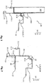
- Fig. 2 shows a sectional drawing in cross section through the front frame section 20 with the rear frame section 30 of an outer frame profile 1 according to the invention lying behind it.
- the outer frame profile 1 shown here is composed of three profile parts 11, 12 and 13.
- the outer frame profile 1 is attached to the front frame section 20 through the first profile part 11 and a third Profile part 13 is formed.
- connection element 80 in the form of a connection profile which is in contact with this in sections and is connected to the profile parts 12 and 13, which is shown in FIG Figure 3 is shown, it can be seen that the front profile part 12 has a different structural height than the rear profile part 13, whereby different substructure heights are configured in the longitudinal extension of the outer frame of the utility vehicle.
- the shape and the overall height of the outer side of the outer frame or the profile part 11 forming the outer side of the outer frame profile 1 remains the same over its entire longitudinal extent, which advantageously creates a step at a transition between the front area 20 and the rear area 30 of the outer frame profile 1 is avoided.
- a lashing eye 42 was added, which is used to secure the load via a tensioning strap or lashing strap passed through the lashing eye 42.
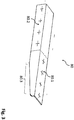
- Fig. 3 shows the connecting element 80 from Figure 2 in a perspective view parallel to the longitudinal extension of the outer frame profile 1.
- the connecting element 80 is designed in the form of a connecting profile with an upper contact surface 80.1 and a lateral contact surface 80.2, via which the connecting element 80 can be connected to the profile parts 11, 12 and 13.
- the lateral contact surface 80.2 is notched in sections in the form of a bevel 80.3 and, when the profile parts 12 and 13 are connected, lies with this bevel 80.3 in the chassis offset area of the utility vehicle.
- the connecting element 80 covers the outer frame profile joint between the profile part 12 and the profile part 13.
- Figure 4 shows that in Figure 2 Outer frame profile 1 shown with a lashing or lashing hook 41 extending through the frame profile 1 or through the outer frame and one received in the shoulder 11.4 Lashing eye 42.
- the lashing hook 41 engages through an opening 40 configured in the frame profile 1.
- the opening is configured in a region of the wall of the frame profile 1, which is reinforced by two profile parts 11 and 12 or 11 and 13 lying against one another, in the present case the wall thickness is doubled.
- Figure 5 shows that in Figure 1 Outer frame profile shown 1.
- an outer frame accommodating a box body this is in Figure 4
- a connection element 3.1, 3.2 formed from two connection elements 3.1 and 3.2 is connected to the outer frame.
- recesses are provided in the profile part.
- the connection elements 3.1 and 3.2 are arranged on a common base support 120 in the form of a flat iron and form a modular unit.
- connection elements on the base carrier simplifies the assembly of two or more connection elements 3.1,3.2 on the outer frame formed from the outer frame profile 1 according to the invention, and on the other hand the stop area of the stanchion on the outer frame of the chassis of the utility vehicle is reinforced.
- a further stabilizing effect of the outer frame reinforced by the base support 120 is that the wall thickness of the base support 120 and the material doubling of the wall thickness through the connection elements 3.1 and 3.2 through their through bores and fastening elements 700, in the form of expansion screws, is another stabilizing effect. which causes an additional stabilization of the attachment of the stanchion to the outer frame.
- the stanchion is advantageous over one from the German patent application 10 2020 102 186.0 Known locking system connected to the outer frame via the connection elements 3.1 and 3.2. Reference is hereby expressly made to the disclosure content of this patent application and this becomes Subject of the present description and thus made the disclosure content of the present application.
- FIG 6 the arrangement of the outer frame profile 1 above a vehicle wheel 300 of a utility vehicle is shown in an overview illustration in cross section through the rear area of the outer frame profile.
- the deformation 13.2 is designed as a clamp into which a splash guard 400 for fastening to the outer frame profile 1 is clamped in the present case.
- the leg 13.1 is slightly deformed outwards (in the illustration) to the left, or this has a bulge that provides free space for the arrangement of the vehicle wheel 300 trains. It is advantageous here that the continuous profile part 11 remains free from deformation in order to form a free space for the vehicle wheel 300 or the vehicle wheels 300.
- Figure 7 shows an outer frame profile 1 according to the invention in a sectional drawing in cross section through the rear frame section 1.
- a pallet stop 500 is arranged on the outer frame profile 1, which via a fastening element 800, which in the present case is in the form of a bolt through the pallet stop 500 and through the outer frame profile 1 in the area of the shoulder 11.4 is guided, attached to the outer frame profile 1.
- the pallet stop 500 advantageously runs parallel in the longitudinal direction to the outer frame profile 1, particularly advantageously over the entire length of the profile part 11.
- the sealing profile 900 is advantageously made of a plastic or a plastic composite material or in the form of a sealing tape, which is made, for example, of a plastic-like or a rubber-like or a rubber-elastic material is designed.
- the possibility of deforming the deformation 13.2 to form a clamping is shown in broken lines.
- Figure 8 shows the rear frame section 30 of the outer frame profile 1 according to the invention Figure 7 with a lashing hook 41 guided through the outer frame profile 1 as a sectional drawing in cross section through the frame profile 10.
- a lashing strap 41.1 is attached to the lashing hook 41 and is used to secure the load.
- a floor panel 1000 is inserted into the undercut 11.7 or glued to the profile part 11.
- the Figure 9 shows the rear frame section 30 of the outer frame profile 1 according to the invention Figure 8 with a lashing eye 42 guided through the outer frame profile 1 as a sectional drawing in cross section through the frame profile 10.
- the lashing eye 42 is shown in two positions, a lower position 42.1 and an upper position 42.2.
- the lashing eye 21 is located in the space formed between the sealing profile 900 and the outer frame profile 1 and is relieved of tension in this position 42.1.
- the lashing eye 42 is received in the shoulder area 11.4 of the outer frame profile 1 in such a way that the lashing eye 42 does not exceed the upper area of the outer frame profile 1 formed by the plateau 11.5
- the truck in the lower position 42.1 is not damaged.
- FIG. 10 a sectional drawing in cross section through the rear frame section 30 of an outer frame profile 1 according to the invention for an outer frame for a utility vehicle.
- the present is as a commercial vehicle body a box body is shown which can be assembled from individual box wall panels 100, as shown in FIG Figure 1 is shown.
- the load is secured using a lashing eye 42, which in the present case is threaded into the outer frame profile 1 via the shoulder area 11.4 and engages in the lashing eye 42 when the hook 41.3, to which a lashing item 41.1 is attached, is threaded.
- the panels 100 cover the holes 40 for receiving the lashing hooks 41.
Landscapes
- Engineering & Computer Science (AREA)
- Chemical & Material Sciences (AREA)
- Combustion & Propulsion (AREA)
- Transportation (AREA)
- Mechanical Engineering (AREA)
- Body Structure For Vehicles (AREA)
Abstract
Description
- Die vorliegende Erfindung betrifft ein Außenrahmenprofil für einen Außenrahmen für ein Nutzfahrzeug, insbesondere für ein Chassis eines Nutzfahrzeuges, welches aus wenigstens einem Rahmenprofil aus zumindest drei Profilteilen mit gleicher oder unterschiedlicher Wandstärke gebildet ist, mit einem ersten Profilteil, das zumindest abschnittsweise die Außenseite des Außenrahmens bildet, mit zumindest einem vorderen Rahmenabschnitt und zumindest einem hinteren Rahmenabschnitt, wobei an dem vorderen Rahmenabschnitt ein zweites Profilteil mit einer niedrigen Höhe zumindest abschnittweise an dem ersten Profilteil derart anliegt, und wobei an dem hinteren Rahmenabschnitt ein drittes Profilteil mit einer zu dem zweiten Profilteil höheren Aufbauhöhe zumindest abschnittweise an dem ersten Profilteil derart anliegt, dass unterschiedliche Unterbauhöhen in Längserstreckung des Rahmenprofils ausgebildet sind, nach dem Oberbegriff von Anspruch 1.
- Aus der
DE102014103156A1 ist ein Nutzfahrzeugaufbau bekannt, insbesondere ein Schiebeplanenaufbau, mit wenigstens einer seitlichen Runge, die sich zwischen einem Dach und einem Boden des Nutzfahrzeugaufbaus erstreckt, und einer Seitenplane, die in einem Schließzustand über die Runge gespannt ist. Das untere Längsende der Runge ist außen an einem Außenrahmen des Nutzfahrzeugaufbaus befestigt. - Die
DE19706493A1 betrifft Aufbauten für Lkw-Zugfahrzeuge, Zugkabelanhänger, Zentralachsanhänger und Sattelanhänger. - Bei den bekannten Nutzfahrzeugaufbauten ist nachteilig, dass diese spezielle Ausgestaltungen von Außenrahmen benötigen, um unterschiedliche Aufbauten ausbilden zu können. Bei den für die bekannten Nutzfahrzeugaufbauten verwendeten Außenrahmenstrukturen ist zudem nachteilig, dass diese in unterschiedlich beanspruchten Bereichen stets die gleiche Wandstärke aufweisen. Für die Ladungssicherung durch den Außenrahmen durchgeführte Zurr- oder Verzurrhaken verursachen beispielsweise bei unzureichender Wandstärke des Außenrahmenprofils bei Zugbelastung Verformungen des Außenrahmens.
- Aufgabe der Erfindung ist es, die aus dem Stand der Technik bekannten Nutzfahrzeugaufbauten zumindest teilweise zu verbessern. Insbesondere ist es die Aufgabe der vorliegenden Erfindung einen Außenrahmen derart auszugestalten, dass dieser in besonders beanspruchten Bereichen formstabil bleibt.
- Die voranstehende Aufgabe wird durch ein Außenrahmenprofil für einen Außenrahmen für ein Nutzfahrzeug, insbesondere für ein Chassis eines Nutzfahrzeuges mit den Merkmalen des Anspruchs 1, durch einen Außenrahmen, umfassend das erfindungsgemäße Außenrahmenprofil mit den Merkmalen des Anspruchs 11 sowie durch ein Chassis für einen Nutzfahrzeugaufbau, umfassend den erfindungsgemäßen Außenrahmen mit den Merkmalen des Anspruchs 12 gelöst. Weitere Vorteile, Merkmale und Details der Erfindung ergeben sich aus den Unteransprüchen, der Beschreibung und den Zeichnungen. Dabei gelten Merkmale und Details, die im Zusammenhang mit dem erfindungsgemäßen Außenrahmenprofil beschrieben sind, selbstverständlich auch im Zusammenhang mit dem erfindungsgemäßen Außenrahmen und dem erfindungsgemäßen Chassis und jeweils umgekehrt, so dass bezüglich der Offenbarung zu den einzelnen Erfindungsaspekten stets wechselseitig Bezug genommen wird, bzw. werden kann.
- Das erfindungsgemäße Außenrahmenprofil für einen Außenrahmen für ein Nutzfahrzeug, insbesondere für ein Chassis eines Nutzfahrzeuges, welches aus wenigstens einem Rahmenprofil aus zumindest drei Profilteilen mit gleicher oder unterschiedlicher Wandstärke gebildet ist, mit einem ersten Profilteil, das zumindest abschnittsweise die Außenseite des Außenrahmens bildet, mit zumindest einem vorderen Rahmenabschnitt und zumindest einem hinteren Rahmenabschnitt, wobei an dem vorderen Rahmenabschnitt ein zweites Profilteil mit einer niedrigen Höhe zumindest abschnittweise an dem ersten Profilteil derart anliegt, und wobei an dem hinteren Rahmenabschnitt ein drittes Profilteil mit einer zu dem zweiten Profilteil höheren Aufbauhöhe zumindest abschnittweise an dem ersten Profilteil derart anliegt, dass unterschiedliche Unterbauhöhen in Längserstreckung des Rahmenprofils ausgebildet sind, schließt die technische Lehre ein, dass in den Abschnitten, in denen das zweite Profilteil und das dritte Profilteil an dem ersten Profilteil anliegen, sich die Wandstärke des ersten Profilteils mit der Wandstärke des zweiten Profilteils und/oder der Wandstärke des dritten Profilteils addiert.
- Im Sinne der vorliegenden Erfindung soll als "Außenrahmen" ein den Ladeboden eines Nutzfahrzeuges zumindest abschnittsweise umgrenzender Rahmen verstanden werden. Entsprechend ist das in dieser Anmeldung offenbarte Außenrahmenprofil als ein erster Rahmenabschnitt des Außenrahmens zu verstehen, welches in Längserstreckung auf einer Seite des Nutzfahrzeuges ausgebildet ist und das spiegelsymmetrisch auch auf der anderen Seite des Nutzfahrzeuges als zweiter Rahmenabschnitt des Außenrahmens ausgebildet ist, das mit den gleichen oder zu dem anderen Außenrahmenprofil unterschiedlichen Funktionen ausgestaltet ist.
- Als "Addierung der Wandstärken" soll im Sinne der vorliegenden Erfindung eine abschnittsweise Verstärkung der Wand des Rahmenprofils in den Bereichen, in denen das erste Profilteil mit einem weiteren daran anliegenden Profilteil "hinterfüttert" ist, verstanden werden. Diese bereichsweise Ausgestaltung dient auch insgesamt zur strukturellen Stabilisierung bzw. zur Versteifung des ersten Profilteils und somit insgesamt zur Ausbildung eines stabilen und multifunktionellen Außenrahmens.
- Im Sinne der vorliegenden Erfindung soll als "Nutzfahrzeug" insbesondere ein Trailer, wie beispielsweise ein Curtainsider, ein Mega-Curtainsider oder auch ein Trailer mit Kofferaufbau verstanden werden, wobei im Fall eines Planenaufbaus Rungen als vertikale Verstrebungen zwischen dem Dach des Trailers und dem Ladeboden des Trailers dienen oder im Falle eines Kofferaufbaus sich Paneele auf dem Außenrahmen abstützen und mit diesem verbunden sind.
- Im Gegensatz zu den bekannten Außenrahmen, die aus einem Profil mit durchgehend gleicher Wandstärke ausgebildet sind, sind die beispielsweise durch Zugbelastung bei der Ladungssicherung stark belasteten Bereiche des die Außenseite des erfindungsgemäßen Außenrahmenprofilteils bildenden Profilteils durch die Hinterlegung zumindest eines weiteren Rahmenprofilteils verstärkt. Dadurch addieren sich erfindungsgemäß die Wandstärken der aneinander liegenden Profilteile. Zudem kann durch die Ausgestaltung eines Rahmenprofils aus zumindest drei Profilteilen bei einem durchgehenden ersten Profilteil, welches die Außenseite des Außenrahmens bzw. des Außenrahmenprofils bildet, das erste Profilteil unverändert für verschiedene Nutzfahrzeugaufbauten und insbesondere vorteilhaft ohne eine Ausbildung einer Stufe im Übergang vom hinteren Bereich zum vorderen Bereich des Außenrahmens ausgestaltet werden. Durch das Anlegen und die Verbindung des ersten Profilteils mit einem zweiten Profilteil kann ein vorderer Bereich des erfindungsgemäßen Außenrahmens mit einer geringeren Höhe im Vergleich zu einer höheren Höhe im hinteren Bereich des Außenrahmens durch das Anlegen und die Verbindung mit einem für den hinteren Bereich des Außenrahmens ausgebildeten dritten Rahmenprofilteil ausgestaltet werden. Die Anforderungen für die unterschiedlichen Höhen im vorderen und im hinteren Bereich des Außenrahmens, die sich aus den Funktionen eines Chassis für einen Nutzfahrzeugaufbau ergeben, wirken sich dabei erfindungsgemäß nicht auf die Architektur des die Außenseite des Außenrahmen bildenden ersten Profilteils aus. Der stufenlos ausgebildete Außenrahmen bildet dabei erfindungsgemäß einen Systemanschluss für Kofferpaneele als auch für Planenaufbauten.
- Aus dem Stand der Technik sind für die Außenrahmenprofile Wandstärken von 3 mm bis 4 mm bekannt. Bei den Profilen handelt es sich in üblicher Weise um Strangpressprofile oder um zusammengeschweißte Profilteile, um einen vorderen und einen hinteren Bereich des Außenrahmens auszugestalten. Dadurch entsteht im Fahrgestellkröpfungsbereich bei gleichbleibender Wandstärke der aneinandergefügten Profilteile eine Stufe zwischen dem hinteren und dem vorderen Bereich des Außenrahmens.
- In vorteilhafter Weise wird durch das Anlegen die Verbindung des zweiten und des dritten Profilteils an das erste Profilteil bei gleicher Wandstärke für das erste Profilteil, das zweite Profilteil und das dritte Profilteil das Rahmenprofil in den Abschnitten, in denen das zweite Profilteil und das dritte Profilteil an dem ersten Profilteil anliegen, die Wandstärke des den Außenrahmen bildenden Rahmenprofils verdoppelt.
- Vorzugsweise wird die erhöhte oder verstärkte Wandstärke, insbesondere die Materialdopplung, in Abschnitten des Rahmenprofils ausgebildet, in denen Öffnungen für Befestigungselemente vorgesehen sind. Die Öffnungen dienen vorteilhaft zum Ein- bzw. Durchgriff von Zurrhaken oder zum Einlassen von Zurrösen für eine Ladungssicherung mittels Spanngurten. Die Spanngurte sind in üblicher Weise als 2 Tonnengurte und bis zu 4 Tonnengurte ausgelegt. Die Wandstärke für die Profilteile des Rahmenprofils für den erfindungsgemäßen Außenrahmen liegt vorteilhaft zwischen 1,5 mm bis 5 mm, bevorzugt zwischen 2 mm bis 4 mm und besonders bevorzugt weisen die Profilteile für den erfindungsgemäßen Außenrahmen eine Wandstärke von 2 mm auf. Bei Doppelung der Wandstärke ergibt sich in den besonders belasteten Bereichen des Außenrahmens dadurch eine Wandstärke von 4 mm, was gegenüber den bekannten Wandstärken von 3 mm eine Bördelung durch Zug über die Spanngurte bei der Ladungssicherung wirkungsvoll verhindert. Zudem sind die Profilteile vorzugsweise aus einem Material mit hochfester Materialgüte ausgebildet, was sich zusätzlich vorteilhaft auf die Stabilität des erfindungsgemäßen Außenrahmenprofils ausübt. Vorteilhaft wirkt die verstärkte Wandstärke, insbesondere in dem zum Fahrzeugboden hin liegenden Schulterbereich des erfindungsgemäßen Außenrahmenprofils, einem Abbiegen oder Verbiegen des Profils bei Druckbelastung auf den Fahrzeugboden, beispielsweise durch Befahren mit einem Stapler oder bei Beförderung von Transportgut, entgegen.
- Wie bereits beschrieben, ist das erste Profilteil in Längserstreckung des Rahmenprofils mit einer gleichbleibenden Höhe stufenlos ausgebildet, wobei das erfindungsgemäße Außenrahmenprofil erfindungsgemäß eine vordere und eine hintere Höhe aufweist. Daraus ergibt sich vorteilhaft, dass Kofferpaneele oder eine Plane mit gleichbleibender Höhe für einen Nutzfahrzeugaufbau ausgestaltet werden können. Die Ausgestaltung der aus dem Stand der Technik bekannten Kofferpaneele mit unterschiedlicher Bauhöhe oder die an eine Stufe im Außenrahmen angepasste Plane entfällt vorteilhaft bei der erfindungsgemäßen stufenlosen Ausgestaltung des aus zumindest drei Profilteilen zusammengesetzten erfindungsgemäßen Rahmenprofils für einen Außenrahmen.
- Soll als Nutzfahrzeug ein Standardtrailer ausgestaltet werden kann das erfindungsgemäße Außenrahmenprofil auch nur aus zwei Profilteilen gebildet werden, nämlich dem ersten und dem zweiten Profilteil, welche dann gemeinsam den hinteren Bereich und den vorderen Bereich des Außenrahmenprofils für den Außenrahmen bilden. Aufgrund der Abmessungen der Fahrzeugräder, die bei Standardtrailern eingesetzt werden ist eine unterschiedliche Unterbauhöhe zwischen dem vorderen und dem hinteren Bereich des Nutzfahrzeuges nicht notwendig. Die für das erfindungsgemäße Außenrahmenprofil genannten Funktionen und Eigenschaften bleiben auch für diese besondere Konstruktion aus nur zwei Profilteilen für den Bau von Standardtrailern erhalten.
- Vorzugsweise ist das erste Profilteil des erfindungsgemäßen Rahmenprofils für den Außenrahmen als ein Profil, das durchlaufend ist, ausgebildet. Demgegenüber sind zur Ausgestaltung eines vorderen und eines hinteren Bereiches das zweite Profilteil und das dritte Profilteil an das erste Profilteil angelegt und mit diesem verbunden, wobei das zweite Profilteil vorzugsweise einmal gestoßen ist, nämlich an dem dritten Profilteil stirnseitig an diesem anliegt. Zur Verbindung zwischen dem zweiten und dem dritten Profilteil dient vorteilhaft zumindest ein Verbindungelement, das vorteilhaft zumindest abschnittsweise in Längserstreckung des Rahmenprofils an dem zweiten Profilteil und dem dritten Profilteil zur Anlage gebracht werden kann. Die Verbindung zwischen dem Verbindungselement und dem zweiten Profilteil kann als zumindest kraft- und/oder form- und/oder stoffschlüssige Verbindung ausgeführt werden. Vorzugsweise werden die zuvor genannten Teile miteinander verklebt, verschweißt, verschraubt, vernietet oder geclincht. Der Stoß zwischen dem dritten und dem zweiten Profilteil liegt vorteilhaft im oder hinter dem Fahrgestellkröpfungsbereichs bzw. im Bereich von Stützwinden des Nutzfahrzeugaufbaus.
- In vorteilhafter Weise weist das erste Profilteil zumindest abschnittsweise eine Umformung in Form einer Hinterschneidung oder eines Hinterschnitts auf. Die Hinterschneidung dient vorteilhaft als Bodenauflage, nämlich zur Aufnahme von Bodenpaneelen. Die in die Hinterschneidung eingeführten Bodenpaneele werden vorzugsweise mit dem ersten Rahmenprofilteil verklebt und bilden insgesamt über die Längserstreckung mehrerer an dem erfindungsgemäßen Außenrahmen verklebter Bodenpaneele eine Scheibe, die vorteilhaft die Fahreigenschaften des mit dem erfindungsgemäßen Außenrahmen aufgebauten Nutzfahrzeuges gegenüber den bekannten Nutzfahrzeugen verbessern.
- Vorzugsweise weist das dritte Profilteil eine parallel zur Längserstreckung des Rahmenprofils ausgebildete Umformung an einem orthogonal zur Längserstreckung des dritten Profilteils liegenden nach unten weisenden Schenkel auf. Die Umformung erfolgt vorteilhaft in Form einer U-förmigen Verformung. Neben stabilisierenden Eigenschaften, nämlich zu unterseitigen Versteifung des dritten Profils, dient die Umformung vorteilhaft auch als Befestigungsaufnahme, vorteilhaft in Form einer Klemmung durch Zusammenführen der beiden Schenkel der U-förmigen Verformung. Neben der beispielhaften Befestigung von Anbauteilen wie beispielsweise eine Seitenbeleuchtung, ein Spritzschutz, vorteilhaft im hinteren Bereich des Außenrahmens, ein Werkzeugkasten und/oder ein Unterfahrschutz, kann die Umformung an dem nach unten weisenden Schenkel auch als Leitungsbahn zum Verlegen von elektrischen oder fluidtechnischen Verbindungen verwendet werden. Die Befestigung der Anbauteile an dem Profilteil kann auch mittels Befestigungselementen, wie beispielsweise Schrauben oder Nieten, erfolgen.
- In vorteilhafter Weise weist das erste Profilteil eine parallel zur Längserstreckung des Rahmenprofils ausgebildete Umformung an einem orthogonal zur Längserstreckung des ersten Profilteils liegenden nach unten weisenden Schenkel auf. Die Umformung ist vorzugsweise in Form einer nach oben hin sich verjüngenden Öse oder vorteilhaft in Form eines Schäkels ausgebildet. Insbesondere ist die untere Kante des Schenkels in Form einer Abrundung ausgestaltet. Die Umformung mit der Abrundung dient vorteilhaft zum einen zur unterseitigen Versteifung des nach unten weisenden Schenkels des ersten Profils und zum anderen wird durch die Abrundung die Ausbildung einer Schnittkante vermieden. Bei Planenaufbauten dient die Umformung vorteilhaft zur Umlage einer Plane und der Befestigung der Plane mittels eines an der Umformung angreifenden Planenspanners. Die um die Umformung umgelegte Plane in Verbindung mit dem an der Umformung angreifenden Planenspanners ermöglicht in vorteilhafter Weise eins Abdichtung des Laderaums, der von dem Außenrahmen zumindest abschnittsweise umgriffen wird.
- Ein weiterer Erfindungsaspekt der vorliegenden Erfindung ist ein aus dem erfindungsgemäßen Außenrahmenprofil gebildeter Außenrahmen. Der Außenrahmen umfasst dabei zumindest zwei erfindungsgemäße Außenrahmenprofile die parallel und beabstandet zueinander angeordnet sind. Zwischen den beiden Außenrahmeprofilteilen liegt der Fahrzeugboden des Nutzfahrzeuges in Form von mit den Außenrahmenprofilteilen verbundenen Bodenpaneelen.
- Schließlich ist ein weiterer Erfindungsaspekt der vorliegenden Erfindung ein Chassis für einen Nutzfahrzeugaufbau, umfassend zumindest den erfindungsgemäßen Außenrahmen. Der erfindungsgemäße Außenrahmen mit seinem höheren hinteren Bereich und mit seinem niedrigeren vorderen Bereich erlaubt die Ausbildung eines Chassis, wie es für Nutzfahrzeug, insbesondere für Trailer bekannt ist, wobei jedoch erfindungsgemäß das durchlaufende erste Profil, welches auch als Masterprofil bezeichnet werden kann, unterschiedliche Nutzfahrzeugaufbauten zulässt und dieses stufenlos ausgestaltet ist.
- Um hier Wiederholungen bezüglich der Vorteile des erfindungsgemäßen Außenrahmens bzw. des erfindungsgemäßen Chassis für einen Nutzfahrzeugaufbau zu vermeiden, wird auf die Beschreibung der vorteilhaften Ausgestaltungen des erfindungsgemäßen Außenrahmenprofils verwiesen und es wird vollumfänglich auf die Offenbarung durch diese Beschreibung zurückgegriffen und umgekehrt.
- Weitere, die Erfindung verbessernde Maßnahmen werden nachstehend mit der Beschreibung von bevorzugten Ausführungsbeispielen der Erfindung anhand der Figuren näher dargestellt. Dabei können die in den Ansprüchen und in der Beschreibung erwähnten Merkmale jeweils einzeln für sich oder in beliebiger Kombination erfindungswesentlich sein. Dabei ist zu beachten, dass die in den Figuren dargestellten Ausführungsbeispiele nur beschreibenden Charakter haben und diese nicht dazu gedacht ist, die Erfindung in irgendeiner Form einzuschränken.
- Es zeigen:
-
Fig. 1 eine Schnittzeichnung im Querschnitt durch den hinteren Rahmenabschnitt eines erfindungsgemäßen Außenrahmenprofils mit einem als Kofferaufbau ausgestalteten Nutzfahrzeugaufbau, -
Fig. 2 eine Schnittzeichnung im Querschnitt durch den vorderen Rahmenabschnitt im Bereich des Stoßes zwischen dem zweiten und dem dritten Profilteil mit einem die Profilteile verbindenden Verbindungselement eines erfindungsgemäßen Außenrahmenprofils, -
Fig. 3 das Verbindungselement ausFigur 2 in einer perspektivischen Darstellung, -
Fig. 4 eine Schnittzeichnung im Querschnitt durch das Rahmenprofil des erfindungsgemäßen Außenrahmenprofils mit einem durch das Rahmenprofil greifenden Zurrhaken und einer im Rahmenprofil aufgenommenen Zurröse, -
Fig. 5 die Schnittzeichnung des hinteren Rahmenprofils ausFigur 1 mit einem an dem Rahmen angeordneten Anschlusselement für eine Runge, -
Fig. 6 eine Übersichtsdarstellung des Außenrahmenprofils im hinteren Bereich über einem Fahrzeugrad im Querschnitt durch das Rahmenprofil des erfindungsgemäßen Außenrahmenprofils, bzw. im Querschnitt durch das Chassis eine Nutzfahrzeuges, -
Fig. 7 eine Schnittzeichnung im Querschnitt durch den hinteren Rahmenabschnitt eines erfindungsgemäßen Außenrahmenprofils mit einem am Außenrahmenprofil angeordneten Palettenanschlag und einem Dichtungsprofil, -
Fig. 8 zeigt den hinteren Rahmenabschnitt des erfindungsgemäßen Außenrahmenprofils ausFigur 7 mit einem durch das Außenrahmenprofil geführten Zurrhaken als Schnittzeichnung im Querschnitt durch das Rahmenprofil, -
Fig. 9 zeigt den hinteren Rahmenabschnitt des erfindungsgemäßen Außenrahmenprofils ausFigur 8 mit einer durch das Außenrahmenprofil geführten Zurröse als Schnittzeichnung im Querschnitt durch das Rahmenprofil
und -
Fig. 10 zeigt in einer Schnittzeichnung im Querschnitt durch den hinteren Rahmenabschnitt 30 ein erfindungsgemäßes Außenrahmenprofil 1 für einen Außenrahmen für ein Nutzfahrzeug mit Kofferaufbau, bei dem die Ladungssicherung über Zurrösen erfolgt. - In den unterschiedlichen Figuren sind gleiche Teile stets mit denselben Bezugszeichen versehen, weshalb diese in der Regel nur einmal beschrieben werden.
-
Fig. 1 zeigt eine Schnittzeichnung im Querschnitt durch den hinteren Rahmenabschnitt 30 eines erfindungsgemäßen Außenrahmenprofils 1 für einen Außenrahmen für ein Nutzfahrzeug. Vorliegend ist als Nutzfahrzeugaufbau ein Kofferaufbau dargestellt, der aus einzelnen Kofferwandpaneelen 100 zusammengesetzt werden kann. Die Befestigung der Kofferwandpaneele 100 an dem Außenrahmenprofil 1 kann beispielsweise durch Verkleben oder mittels Befestigungselementen, beispielsweise mittels Toptite-Schrauben, erfolgen. An der zum Boden des Nutzfahrzeuges liegenden Seite des Kofferwandpaneels 100 ist eine Scheuerleiste 200 angesetzt. Das dargestellte Außenrahmenprofil 1 setzt sich vorliegend aus drei Profilteilen 11,12,13 zusammen. Im dargestellten hinteren Rahmenabschnitt 30 wird das Außenrahmenprofil 1 durch das erste Profilteil 11 und durch das dritte Profilteil 13 gebildet. Sowohl das erste Profilteil 11 als auch das dritte Profilteil 13 weisen einen nach unten hin weisenden Schenkel 11.1 und 13.1 auf, an deren Enden jeweils eine Umformung 11.2 und 13.2 ausgebildet ist. Die Umformung 11.2 am Schenkel 11.1 dient neben einer unterseitigen Versteifung des Profilteils 11 und zur Vermeidung der Ausbildung einer scharfen Kante des Profilteils 11 insbesondere zum Umlegen einer Plane um die als Abrundung gebildete Umformung 11.2 und für den Eingriff von Planenspannern. Die Umformung 13.2 am Schenkel 13.1 dient neben einer Stabilisierung bzw. unterseitigen Versteifung des Profilteils 13 und zur Vermeidung der Ausbildung einer scharfen Kante als Befestigungsvorrichtung, beispielsweise durch Verschraubung oder Vernietung, für beispielsweise Seitenbeleuchtung, Spritzschutz, Werkzeugkasten oder Unterfahrschutz, oder zum Durchführen von Leitungen, wie elektrischen oder fluidtechnischen Leitungen dienen. Um im hinteren Fahrzeugbereich ausreichend Platz für die am Fahrzeugchassis angeordneten Räder anbieten zu können, kann der Schenkel 13.1 vorteilhaft nach Außen geformt sein, insbesondere in Form einer Ausbuchtung (s. DetailansichtFigur 6 ). Die Umformung 13.2 kann jedoch vorteilhaft auch als Klemmbefestigung mit Klemmwirkung durch Zusammendrücken der beiden Schenkel der U-förmigen Umformung 13.2 ausgebildet werden. Abschnittsweise liegt hinter dem Profilteil 11 das Profilteil 13 an und ist dabei der Form des Profilteils 11 derart nachgebildet bzw. nachgeformt, dass sich im Anlagebereich der beiden Profilteile 11 und 13 insgesamt die Wandstärke beider Profilteile addiert. Vorliegend haben das Profilteil 11 und das Profilteil 13 die gleiche Wandstärke, so dass es bezüglich der addierten Wandstärken zu einer Materialdopplung kommt. Die Materialdopplung der Wandstärke durch Anlage des Profilteils 13 an das Profilteil 11 erfolgt vorliegend bis ca. zur Hälfte eines oberen Plateaus 11.5 des Profilteils 11, welches ca. auf der oberen Höhe von Bodenpaneelen abschließt, die den Fahrzeugboden bilden (vorliegend nicht dargestellt). Durch die Materialdopplung bzw. durch die Addition der Wandstärken der Profilteile 11 und 13 wird auch das Plateau 11.5 verstärkt. Je nach Belastung des Plateaus 11.5 oder des Fahrzeugbodens kann die Anlage des Profilteils 13 an das Profilteil 11 auch weiter geführt werden, nämlich in der Figur bis nach rechts zum Ende des Profilteils 11. Insbesondere die Verstärkung im Schulterbereich 11.4 des ersten Profilteils 11 durch die Anformung und die Anlage des zweiten Profilteils 12 und des dritten Profilteils 13 dient der Abstützung des Plateaus 11.5 und der Bodenaufnahme. Dies führt insgesamt zu einer Stabilisierung eines aus den Außenrahmenprofilen 1 gebildeten Außenrahmens, insbesondere bei Belastung, insbesondere Druckbelastung, auf den Fahrzeugboden. Nach rechts in der Figur fällt das Profilteil 11 nach dem Plateau 11.5 in einem nach unten hin weisenden nicht lotrechten Schenkel 11.6 ab. Durch diese Umformung bildet das Profilteil 11 eine Hinterschneidung 11.7 oder einen Hinterschnitt zur Aufnahme von Bodenpaneelen aus. Die in die Hinterschneidung 11.7 eingeführten Bodenpaneele werden vorzugsweise mit dem Profilteil 11 verklebt und bilden insgesamt über die Längserstreckung des Außenrahmens mehrerer an dem erfindungsgemäßen Außenrahmenprofil 1 verklebter Bodenpaneele eine Scheibe, die die Fahreigenschaften des Nutzfahrzeuges verbessert. Durch Zusammenfügen des ersten den Außenrahmen bildenden Außenrahmenprofils 1 nach Einführung und Verklebung der Bodenpaneele in die Hinterschneidung 11.7 des Rahmen- bzw. Profilteils 11 mit dem zweiten den Außenrahmen bildenden Außenrahmenprofil 1, das wie oben beschrieben spiegelsymmetrisch in Längserstreckung des Nutzfahrzeuges und mit Abstand zu dem ersten Außenrahmenprofil 1 angeordnet wird, um den Außenrahmen, der den Fahrzeugboden zumindest abschnittweise umrahmt bzw. umgrenzt, zu bilden, sind die in die Hinterschneidung 11.7 des Profilteils 11 eingesetzten Bodenpanneele durch die die Hinterschneidung 11.7 bildende Umformung des Profilteils 11 bereits zumindest kraft- und/oder formschlüssig mit den beiden Außenrahmenprofilen 1, die den Außenrahmen bilden, verbunden. -
Fig. 2 zeigt eine Schnittzeichnung im Querschnitt durch den vorderen Rahmenabschnitt 20 mit dem dahinterliegenden hinteren Rahmenabschnitt 30 eines erfindungsgemäßen Außenrahmenprofils 1. Das dargestellte Außenrahmenprofil 1 setzt sich vorliegend aus drei Profilteilen 11, 12 und 13 zusammen. In der Darstellung inFigur 2 auf den vorderen Rahmenabschnitt 20 wird das Außenrahmenprofil 1 durch das erste Profilteil 11 und durch ein drittes Profilteil 13 gebildet. Wie in dem dargestellten Verbindungsbereich zwischen dem zweiten Profilteil 12 und dem dritten Profilteil 13 über ein an diese abschnittsweise anliegendes und mit den Profilteilen 12 und 13 verbundenes Verbindungselement 80 in Form eines Verbindungsprofils, das inFigur 3 dargestellt ist, ist zu erkennen, dass das vordere Profilteil 12 eine andere Bauhöhe als das hintere Profilteil 13 aufweist, wodurch unterschiedliche Unterbauhöhen in Längserstreckung des Außenrahmens des Nutzfahrzeuges ausgestaltet sind. Bei dieser Ausgestaltung bleibt die Form und die Bauhöhe das die Außenseite des Außenrahmens bzw. das die Außenseite des Außenrahmenprofils 1 bildende Profilteil 11 über dessen gesamte Längserstreckung gleich, wodurch vorteilhaft eine Stufe bei einem Übergang zwischen dem vorderen Bereich 20 und dem hinteren Bereich 30 des Außenrahmenprofils 1 vermieden wird. In der Schulter 11.4 ist in derFigur 2 eine Zurröse 42 aufgenommen, die zur Ladungssicherung über einen durch die Zurröse 42 geführten Spanngurt oder Zurrriemen dient. -
Fig. 3 zeigt das Verbindungselement 80 ausFigur 2 in einer perspektivischen Darstellung parallel zur Längserstreckung des Außenrahmenprofils 1. Das Verbindungselement 80 ist in Form eines Verbindungsprofils mit einer oberen Anlagefläche 80.1 und einer seitlichen Anlagefläche 80.2 ausgestaltet, über die das Verbindungselement 80 mit den Profilteilen 11, 12 und 13 verbunden werden kann. In der Figur rechts im vorderen Bereich des Verbindungselements 80 ist die seitliche Anlagefläche 80.2 abschnittsweise in Form einer Abschrägung 80.3 ausgeklinkt und liegt mit dieser Abschrägung 80.3 bei Verbindung der Profilteile 12 und 13 im Fahrgestellkröpfungsbereich des Nutzfahrzeuges. Kurz hinter der Abschrägung 80.3 überdeckt das Verbindungselement 80 den Außenrahmenprofilestoß zwischen dem Profilteil 12 und dem Profilteil 13. -
Figur 4 zeigt das inFigur 2 dargestellte Außenrahmenprofil 1 mit einem durch das Rahmenprofil 1 bzw. durch den Außenrahmen durchgreifenden Zurr- bzw. Verzurrhaken 41 und einem in der Schulter 11.4 aufgenommenen Zurröse 42. Der Zurrhaken 41 greift durch einen im Rahmenprofil 1 ausgestalteten Durchgriff 40 in Form einer Öffnung. Die Öffnung ist in einem Bereich der Wand des Rahmenprofils 1 ausgestaltet, welche durch zwei aneinander liegende Profilteile 11 und 12 oder 11 und 13 verstärkt ist, vorliegend ist die Wandstärke verdoppelt. -
Figur 5 zeigt das inFigur 1 dargestellte Außenrahmenprofil 1. Im Gegensatz zu dem inFigur 1 einen Kofferaufbau aufnehmenden Außenrahmen, ist das inFigur 4 dargestellte gleiche Außenrahmenprofil 1 für Außenrahmen für einen Nutzfahrzeugaufbau mit Plane, beispielsweise für einen Curtainsider- oder Mega-Curtainsideraufbau ausgebildet. Zur Anbindung von Rungen (hier nicht dargestellt) ist ein aus zwei Anschlusselementen 3.1 und 3.2 gebildetes Anschlusselement 3.1,3.2 mit dem Außenrahmen verbunden. Im Bereich der Rungen sind in dem Profilteil 11 Ausnehmungen vorgesehen. Die Anschlusselemente 3.1 und 3.2 sind auf einem gemeinsamen Grundträger 120 in Form eines Flacheisens angeordnet und bilden eine modulare Einheit. Die Montage der Anschlusselemente auf dem Grundträger vereinfacht zum einen die Montage von zwei oder mehr Anschlusselementen 3.1,3.2 an dem aus dem erfindungsgemäßen Außenrahmenprofil 1 gebildeten Außenrahmen, und zum anderen wird der Anschlagbereich der Runge an dem Außenrahmen des Chassis des Nutzfahrzeuges verstärkt. Ein weiterer stabilisierender Effekt der durch den Grundträger 120 verstärkten Außenrahmen ist der, dass die durch die Anschlusselemente 3.1 und 3.2 durch deren Durchgangsbohrungen und durchgeführten Befestigungselemente 700, in Form von Dehnschrauben, um die Wandstärke des Grundträgers 120 und durch die Materialdopplung der Wandstärke verlängert werden, was eine zusätzliche Stabilisierung der Befestigung der Runge an dem Außenrahmen bewirkt. Vorteilhaft wird die Runge über ein aus der Deutschen Patentanmeldung10 2020 102 186.0 bekanntes Verschlusssystem über die Anschlusselemente 3.1 und 3.2 mit dem Außenrahmen verbunden. Auf den Offenbarungsgehalt dieser Patentanmeldung wird hiermit ausdrücklich verwiesen und dieser wird zum Gegenstand der vorliegenden Beschreibung und damit zum Offenbarungsgehalt der vorliegenden Anmeldung gemacht. - In
Figur 6 ist in einer Übersichtsdarstellung die Anordnung des Außenrahmenprofils 1 über einem Fahrzeugrad 300 eines Nutzfahrzeuges im Querschnitt durch den hinteren Bereich des Außenrahmenprofils gezeigt. Die Umformung 13.2 ist als Klemmung ausgebildet, in die vorliegend ein Spritzschutz 400 zur Befestigung an dem Außenrahmenprofil 1 geklemmt ist. Um das Fahrzeugrad 300 relativ zum Außenrahmenprofil 1 aufnehmen und ohne Berührung zum Außenrahmenprofil 1 bewegen zu können, ist der Schenkel 13.1 leicht nach Außen (in der Darstellung) nach links verformt, bzw. dieser weist eine Ausbuchtung auf, die einen Freiraum zur Anordnung des Fahrzeugrades 300 ausbildet. Dabei ist vorteilhaft, dass das durchlaufende Profilteil 11 von einer Verformung zur Bildung eines Freiraumes für das Fahrzeugrad 300 bzw. die Fahrzeugräder 300 befreit bleibt. -
Figur 7 zeigt in einer Schnittzeichnung im Querschnitt durch den hinteren Rahmenabschnitt ein erfindungsgemäßes Außenrahmenprofil 1. Am Außenrahmenprofil 1 ist ein Palettenanschlag 500 angeordnet, der über ein Befestigungselement 800, welches vorliegend in Form eines Bolzens durch den Palettenanschlag 500 und durch das Außenrahmenprofil 1 im Bereich der Schulter 11.4 geführt ist, an dem Außenrahmenprofil 1 befestigt. Der Palettenanschlag 500 verläuft vorteilhaft parallel in Längserstreckung zu dem Außenrahmenprofil 1 insbesondere vorteilhaft über die gesamte Längserstreckung des Profilteils 11. Um ein Eindringen von Feuchtigkeit über in dem Außenrahmenprofil 1 ausgestalteten Löchern zu verhindern, ist unterhalb des Plateaus zwischen dem Profilteil 11 und dem freien Ende des Profilteils 13 ein Dichtungsprofil 900 geklemmt. Das Dichtungsprofil 900 ist vorteilhaft aus einem Kunststoff oder einem Kunststoffverbundmaterial oder in Form eines Dichtungsbandes ausgebildet, das beispielsweise aus einem kunststoffähnlichem oder einem gummiähnlichem oder einem gummielastischen Material ausgestaltet ist. In unterbrochenen Linien ist die Möglichkeit der Verformung der Umformung 13.2 zu einer Klemmung dargestellt. -
Figur 8 zeigt den hinteren Rahmenabschnitt 30 des erfindungsgemäßen Außenrahmenprofils 1 ausFigur 7 mit einem durch das Außenrahmenprofil 1 geführten Zurrhaken 41 als Schnittzeichnung im Querschnitt durch das Rahmenprofil 10. An dem Zurrhaken 41 ist ein Zurrgurt 41.1 befestigt, der zur Ladungssicherung dient. In die Hinterschneidung 11.7 ist ein Bodenpaneel 1000 eingelegt bzw. mit dem Profilteil 11 verklebt. - Die
Figur 9 zeigt den hinteren Rahmenabschnitt 30 des erfindungsgemäßen Außenrahmenprofils 1 ausFigur 8 mit einer durch das Außenrahmenprofil 1 geführten Zurröse 42 als Schnittzeichnung im Querschnitt durch das Rahmenprofil 10. Die Zurröse 42 ist in zwei Stellungen, einer unteren Stellung 42.1 und einer oberen Stellung 42.2 gezeigt. In der unteren Stellung 42.1 befindet sich die Zurröse 21 in dem zwischen dem Dichtungsprofil 900 und dem Außenrahmenprofil 1 gebildeten Raum und ist in dieser Stellung 42.1 zugentlastet. In der unteren Stellung 42.1 ist die Zurröse 42 derart in dem Schulterbereich 11.4 des Außenrahmenprofils 1 aufgenommen, dass die Zurröse 42 den durch das Plateau 11.5 gebildeten oberen Bereich des Außenrahmenprofils 1 nicht übersteigt und wird dadurch bei Belastung des Plateaus 11.5, beispielsweise durch Befahrung mit einem Stapler in der unteren Stellung 42.1 nicht beschädigt. In der dargestellten oberen Stellung 42.2 der Zurröse 42 wird über einen Zurrgut 41.1, der zur Ladungssicherung dient, wobei der Zurrgut 41.1 an einem Haken 41.3 befestigt ist, der in die Zurröse 42 greift, derart Zug auf die Zurröse 42 ausgeübt, dass die Zurröse 42 aus der unteren Stellung 42.1 in die obere Stellung 42.2 geführt wird, die auch als Verzurrstellung bezeichnet werden kann. - Schließlich zeigt
Figur 10 eine Schnittzeichnung im Querschnitt durch den hinteren Rahmenabschnitt 30 eines erfindungsgemäßen Außenrahmenprofils 1 für einen Außenrahmen für ein Nutzfahrzeug. Vorliegend ist als Nutzfahrzeugaufbau ein Kofferaufbau dargestellt, der aus einzelnen Kofferwandpaneelen 100 zusammengesetzt werden kann, wie dieser inFigur 1 dargestellt ist. Die Ladungssicherung erfolgt über eine Zurröse 42, die vorliegend über den Schulterbereich 11.4 in das Außenrahmenprofil 1 eingefädelt wird und beim Einfädeln der Haken 41.3, an dem ein Zurrgut 41.1 befestigt ist, in die Zurröse 42 greift. Im Falle der Ausführung des Nutzfahrzeuges mit Kofferaufbau sind durch die Paneele 100 die Löcher 40 zur Aufnahme der Zurrhaken 41 verdeckt.
Claims (14)
- Außenrahmenprofil (1) für einen Außenrahmen für ein Nutzfahrzeug, insbesondere für ein Chassis eines Nutzfahrzeuges, welches aus wenigstens einem Rahmenprofil (10) aus zumindest drei Profilteilen (11,12,13) mit gleicher oder unterschiedlicher Wandstärke gebildet ist, mit einem ersten Profilteil (11), das zumindest abschnittsweise die Außenseite des Außenrahmenprofils (1) bildet, mit zumindest einem vorderen Rahmenabschnitt (20) und zumindest einem hinteren Rahmenabschnitt (30), wobei an dem vorderen Rahmenabschnitt (20) ein zweites Profilteil (12) mit einer niedrigen Höhe zumindest abschnittweise an dem ersten Profilteil (11) derart anliegt, und wobei an dem hinteren Rahmenabschnitt (30) ein drittes Profilteil (13) mit einer zu dem zweiten Profilteil (12) höheren Aufbauhöhe zumindest abschnittweise an dem ersten Profilteil (11) derart anliegt, dass unterschiedliche Unterbauhöhen in Längserstreckung des Rahmenprofils (10) ausgebildet sind, dadurch gekennzeichnet, dass in den Abschnitten, in denen das zweite Profilteil (12) und das dritte Profilteil (13) an dem ersten Profilteil (11) anliegen, sich die Wandstärke des ersten Profilteils (11) mit der Wandstärke des zweiten Profilteils (12) oder der Wandstärke des dritten Profilteils (13) addiert.
- Außenrahmenprofil (1) nach Anspruch 1, dadurch gekennzeichnet, dass bei gleicher Wandstärke für das erste Profilteil (11), das zweite Profilteil (12) und das dritte Profilteil (13) das Rahmenprofil (10) in den Abschnitten, in denen das zweite Profilteil (12) und das dritte Profilteil (13) an dem ersten Profilteil (11) anliegen, eine Materialdopplung erfährt.
- Außenrahmenprofil (1) nach Anspruch 1 oder 2, dadurch gekennzeichnet, dass die erhöhte Wandstärke, insbesondere die Materialdopplung, zumindest in Abschnitten des Rahmenprofils (10) ausgebildet ist, in denen Öffnungen für Befestigungselemente zur Ladungssicherung vorgesehen sind, insbesondere Verzurröffnungen (40) zum Durchgreifen des Rahmenprofils (10) mit Verzurrhaken (41) und/oder Verzurrösen (42).
- Außenrahmenprofil (1) nach einem der vorherigen Ansprüche, dadurch gekennzeichnet, dass die erhöhte Wandstärke zumindest in einem zum Fahrzeugboden (1000) hin liegenden Schulterbereich (11.4) des Rahmenprofils (10) durch Anformung und Anlage des zweiten Profilteils (12) und/oder dritten Profilteils (13) an das erste Profilteil (11) ausgebildet ist, und der verstärkte Schulterbereich (11.4) einer Abstützung eines Plateaus (11.5) und/oder einer Bodenaufnahme (11.7) dient, wodurch ein Abbiegen oder Verbiegen des Rahmenprofils (10) bei Druckbelastung auf den Fahrzeugboden (1000) entgegengewirkt werden kann.
- Außenrahmenprofil (1) nach Anspruch 3 oder 4, dadurch gekennzeichnet, dass der Schulterbereich (11.4) zur Aufnahme von Verzurrösen (11.4) dient, insbesondere die in dem Schulterbereich (11.4) aufgenommenen Verzurrösen (11.4) für eine Ladungssicherung für ein als Kofferaufbau aus Paneelen (100) ausgestaltetes Nutzfahrzeug dient.
- Außenrahmenprofil (1) nach einem der vorherigen Ansprüche, dadurch gekennzeichnet, dass das erste Profilteil (11) in Längserstreckung des Rahmenprofils (10) durchlaufend mit gleicher Höhe stufenlos ausgebildet ist.
- Außenrahmenprofil (1) nach einem der vorherigen Ansprüche, dadurch gekennzeichnet, dass das zweite Profilteil (12) und das dritte Profilteil (13) über zumindest ein Verbindungelement (80), insbesondere welches zumindest abschnittsweise in Längserstreckung des Rahmenprofils (10) an dem zweiten Profilteil (12) und dem dritten Profilteil (13) zur Anlage gebracht werden kann, miteinander verbunden werden können.
- Außenrahmenprofil (1) nach einem der vorherigen Ansprüche, dadurch gekennzeichnet, dass das erste Profilteil (11) zumindest abschnittsweise eine Umformung in Form einer Hinterschneidung (11.7) aufweist, welche zur zumindest kraft- und/oder formschlüssigen Verbindung mit Bodenpaneelen dient.
- Außenrahmenprofil (1) nach einem der vorherigen Ansprüche, dadurch gekennzeichnet, dass das dritte Profilteil (13) eine parallel zur Längserstreckung des Rahmenprofils (10) ausgebildete Umformung (13.2) an einem orthogonal zur Längserstreckung des dritten Profilteils (13) liegenden nach unten weisenden Schenkel (13.1) aufweist, insbesondere in Form einer U-förmigen Verformung.
- Außenrahmenprofil (1) nach Anspruch 9, dadurch gekennzeichnet, dass die Umformung (13.2) zur Befestigung von Anbauteilen mittel Befestigungselementen und/oder zum Durchführen von elektrischen oder fluidtechnischen Leitungen ausgebildet ist und/oder als Klemmung zur Befestigung von Anbauteilen durch Verformung ausgebildet werden kann.
- Außenrahmenprofil (1) nach einem der vorherigen Ansprüche, dadurch gekennzeichnet, dass das erste Profilteil (11) eine parallel zur Längserstreckung des Rahmenprofils (10) ausgebildete Umformung (11.2) an einem orthogonal zur Längserstreckung des ersten Profilteils (11) liegenden nach unten weisenden Schenkel (11.1) aufweist, insbesondere in Form einer nach oben hin sich verjüngenden Öse.
- Außenrahmenprofil (1) nach Anspruch 11, dadurch gekennzeichnet, dass die Umformung (11.1) als Versteifung des ersten Profilteils (11) und/oder zum Umschlaufen einer freien Kante einer Plane und/oder als Widerlager zum Festlegen eines Seitenplanenspanners ausgebildet ist.
- Außenrahmen, umfassend zumindest zwei Außenrahmenprofile (1) nach einem der vorhergehenden Ansprüche 1 bis 12, wobei die zwei Außenrahmenprofile (1) spiegelsymmetrisch in Längserstreckung und parallel zueinander angeordnet sind.
- Chassis für einen Nutzfahrzeugaufbau, umfassend zumindest den Außenrahmen nach Anspruch 13, der aus zumindest zwei Außenrahmenprofilen (1) nach einem der vorhergehenden Ansprüche 1 bis 12 ausgestaltet ist.
Applications Claiming Priority (1)
| Application Number | Priority Date | Filing Date | Title |
|---|---|---|---|
| DE102020107823.4A DE102020107823B4 (de) | 2020-03-20 | 2020-03-20 | Außenrahmenprofil für einen Außenrahmen für ein Nutzfahrzeug, Außenrahmen für ein Nutzfahrzeug, Außenrahmen und Chassis für einen Nutzfahrzeugaufbau |
Publications (3)
| Publication Number | Publication Date |
|---|---|
| EP3882109A1 true EP3882109A1 (de) | 2021-09-22 |
| EP3882109C0 EP3882109C0 (de) | 2024-07-31 |
| EP3882109B1 EP3882109B1 (de) | 2024-07-31 |
Family
ID=75438548
Family Applications (1)
| Application Number | Title | Priority Date | Filing Date |
|---|---|---|---|
| EP21000079.0A Active EP3882109B1 (de) | 2020-03-20 | 2021-03-20 | Aussenrahmenprofil für einen aussenrahmen für ein nutzfahrzeug |
Country Status (2)
| Country | Link |
|---|---|
| EP (1) | EP3882109B1 (de) |
| DE (1) | DE102020107823B4 (de) |
Families Citing this family (3)
| Publication number | Priority date | Publication date | Assignee | Title |
|---|---|---|---|---|
| DE102020129513A1 (de) | 2020-11-09 | 2022-05-12 | CTV GmbH & Co. kg | Bausatzsysteme zur teilweisen oder vollständigen Montage eines Nutzfahrzeuges |
| DE102020129508B4 (de) | 2020-11-09 | 2025-02-13 | CTV GmbH & Co. kg | Querträger für eine Fahrgestellkonstruktion eines hinteren Fahrgestells für ein Nutzfahrzeug |
| DE102020129504A1 (de) | 2020-11-09 | 2022-05-12 | CTV GmbH & Co. kg | Fahrgestellkonstruktion für ein Nutzfahrzeug |
Citations (4)
| Publication number | Priority date | Publication date | Assignee | Title |
|---|---|---|---|---|
| DE19706493A1 (de) | 1997-02-19 | 1998-08-20 | Sommer Fahrzeugbau Gmbh & Co | LKW-Aufbau |
| DE10163360A1 (de) * | 2000-12-22 | 2002-06-27 | Eurocon Oy Hyrylae | Laderaumkonstruktion und Verfahren zu deren Herstellung |
| EP2708450A1 (de) * | 2012-09-14 | 2014-03-19 | Sommer GmbH | Außenrahmen für einen Lastfahrzeug-Aufbau |
| DE102014103156A1 (de) | 2014-03-10 | 2015-09-10 | Kögel Trailer GmbH & Co. KG | Nutzfahrzeugaufbau, insbesondere Schiebeplanenaufbau, Nutzfahrzeug mit einem derartigen Nutzfahrzeugaufbau und Herstellungsverfahren |
Family Cites Families (3)
| Publication number | Priority date | Publication date | Assignee | Title |
|---|---|---|---|---|
| EP2910418B1 (de) | 2014-02-20 | 2019-02-13 | Schmitz Cargobull AG | Ladungssicherungseinrichtung für ein Nutzfahrzeug |
| DE102017208175B4 (de) | 2017-05-15 | 2021-09-30 | Kipp Gmbh & Co. Kg | Lastschiene für ein Kraftfahrzeug sowie Laderaum und Kraftfahrzeug mit einer Lastschiene |
| DE102020102186B4 (de) | 2020-01-29 | 2023-12-14 | Peter Schmitz | Verschlusssystem zur lösbaren Befestigung einer Runge an ein Nutzfahrzeug |
-
2020
- 2020-03-20 DE DE102020107823.4A patent/DE102020107823B4/de active Active
-
2021
- 2021-03-20 EP EP21000079.0A patent/EP3882109B1/de active Active
Patent Citations (4)
| Publication number | Priority date | Publication date | Assignee | Title |
|---|---|---|---|---|
| DE19706493A1 (de) | 1997-02-19 | 1998-08-20 | Sommer Fahrzeugbau Gmbh & Co | LKW-Aufbau |
| DE10163360A1 (de) * | 2000-12-22 | 2002-06-27 | Eurocon Oy Hyrylae | Laderaumkonstruktion und Verfahren zu deren Herstellung |
| EP2708450A1 (de) * | 2012-09-14 | 2014-03-19 | Sommer GmbH | Außenrahmen für einen Lastfahrzeug-Aufbau |
| DE102014103156A1 (de) | 2014-03-10 | 2015-09-10 | Kögel Trailer GmbH & Co. KG | Nutzfahrzeugaufbau, insbesondere Schiebeplanenaufbau, Nutzfahrzeug mit einem derartigen Nutzfahrzeugaufbau und Herstellungsverfahren |
Also Published As
| Publication number | Publication date |
|---|---|
| EP3882109C0 (de) | 2024-07-31 |
| DE102020107823A1 (de) | 2021-09-23 |
| EP3882109B1 (de) | 2024-07-31 |
| DE102020107823B4 (de) | 2022-01-05 |
Similar Documents
| Publication | Publication Date | Title |
|---|---|---|
| DE69606758T2 (de) | Lastkraftwagen-Planenabdeckungs-Vorrichtung | |
| EP3882109B1 (de) | Aussenrahmenprofil für einen aussenrahmen für ein nutzfahrzeug | |
| DE102010030674A1 (de) | Dachträger für ein Fahrzeug | |
| DE10292035B4 (de) | Fahrzeugaufbau | |
| DE2945550A1 (de) | Lastentraggestell | |
| DE102018118832A1 (de) | Fahrzeug-Seitenteilstruktur | |
| EP0925975A2 (de) | Fahrzeugaufbau für Nutzfahrzeuge | |
| DE102015108782B4 (de) | Fahrzeugaufbau, insbesondere für Nutzfahrzeuge, Nutzfahrzeug mit einem solchen Fahrzeugaufbau und Herstellungsverfahren | |
| EP1107898B1 (de) | Seitenplanenaufhängung | |
| EP2708450B1 (de) | Außenrahmen für einen Lastfahrzeug-Aufbau | |
| EP3882083B1 (de) | Absenkbare transportguthaltevorrichtung, montagesatz und -verfahren | |
| DE6902568U (de) | Stossstange fuer kraftfahrzeuge | |
| DE202006010594U1 (de) | Dachplanenanordnung für einen Nutzfahrzeugaufbau | |
| DE4333314C2 (de) | Rahmen für Nutzfahrzeuge | |
| DE102017111235B4 (de) | Nutzfahrzeugaufbau, Dachplaneneinheit für einen Nutzfahrzeugaufbau sowie Schiebeverdeck und Nutzfahrzeug | |
| DE60132316T2 (de) | Sattelanhänger mit zusammensetzbarem aufbau | |
| DE102020102186A1 (de) | Verschlusssystem zur lösbaren Befestigung einer Runge an ein Nutzfahrzeug | |
| DE19720525C2 (de) | Plane für Lastfahrzeuge | |
| DE10013239A1 (de) | Trailer-Anhänger | |
| EP1785338A2 (de) | Runge für einen Nutzfahrzeug- oder Anhängerdachaufbau | |
| DE69601820T2 (de) | Gelenktürsystem für Fahrzeuge, Behälter und ähnliche Verwendungen | |
| DE102010045264B4 (de) | Lochprofilschiene | |
| DE102020119447A1 (de) | Schiebeverdeck für eine Dachöffnung eines Nutzfahrzeug-Laderaums | |
| EP3546260B1 (de) | Planenverschlusselement, plane und fahrzeugaufbau | |
| DE10155728A1 (de) | Fahrzeug mit Ladeboden |
Legal Events
| Date | Code | Title | Description |
|---|---|---|---|
| PUAI | Public reference made under article 153(3) epc to a published international application that has entered the european phase |
Free format text: ORIGINAL CODE: 0009012 |
|
| STAA | Information on the status of an ep patent application or granted ep patent |
Free format text: STATUS: THE APPLICATION HAS BEEN PUBLISHED |
|
| AK | Designated contracting states |
Kind code of ref document: A1 Designated state(s): AL AT BE BG CH CY CZ DE DK EE ES FI FR GB GR HR HU IE IS IT LI LT LU LV MC MK MT NL NO PL PT RO RS SE SI SK SM TR |
|
| STAA | Information on the status of an ep patent application or granted ep patent |
Free format text: STATUS: REQUEST FOR EXAMINATION WAS MADE |
|
| 17P | Request for examination filed |
Effective date: 20220317 |
|
| RBV | Designated contracting states (corrected) |
Designated state(s): AL AT BE BG CH CY CZ DE DK EE ES FI FR GB GR HR HU IE IS IT LI LT LU LV MC MK MT NL NO PL PT RO RS SE SI SK SM TR |
|
| STAA | Information on the status of an ep patent application or granted ep patent |
Free format text: STATUS: EXAMINATION IS IN PROGRESS |
|
| 17Q | First examination report despatched |
Effective date: 20220801 |
|
| GRAP | Despatch of communication of intention to grant a patent |
Free format text: ORIGINAL CODE: EPIDOSNIGR1 |
|
| STAA | Information on the status of an ep patent application or granted ep patent |
Free format text: STATUS: GRANT OF PATENT IS INTENDED |
|
| INTG | Intention to grant announced |
Effective date: 20240305 |
|
| GRAS | Grant fee paid |
Free format text: ORIGINAL CODE: EPIDOSNIGR3 |
|
| GRAA | (expected) grant |
Free format text: ORIGINAL CODE: 0009210 |
|
| STAA | Information on the status of an ep patent application or granted ep patent |
Free format text: STATUS: THE PATENT HAS BEEN GRANTED |
|
| AK | Designated contracting states |
Kind code of ref document: B1 Designated state(s): AL AT BE BG CH CY CZ DE DK EE ES FI FR GB GR HR HU IE IS IT LI LT LU LV MC MK MT NL NO PL PT RO RS SE SI SK SM TR |
|
| REG | Reference to a national code |
Ref country code: CH Ref legal event code: EP Ref country code: GB Ref legal event code: FG4D Free format text: NOT ENGLISH |
|
| REG | Reference to a national code |
Ref country code: DE Ref legal event code: R096 Ref document number: 502021004534 Country of ref document: DE |
|
| REG | Reference to a national code |
Ref country code: IE Ref legal event code: FG4D Free format text: LANGUAGE OF EP DOCUMENT: GERMAN |
|
| U01 | Request for unitary effect filed |
Effective date: 20240821 |
|
| U07 | Unitary effect registered |
Designated state(s): AT BE BG DE DK EE FI FR IT LT LU LV MT NL PT RO SE SI Effective date: 20240902 |
|
| PG25 | Lapsed in a contracting state [announced via postgrant information from national office to epo] |
Ref country code: NO Free format text: LAPSE BECAUSE OF FAILURE TO SUBMIT A TRANSLATION OF THE DESCRIPTION OR TO PAY THE FEE WITHIN THE PRESCRIBED TIME-LIMIT Effective date: 20241031 |
|
| PG25 | Lapsed in a contracting state [announced via postgrant information from national office to epo] |
Ref country code: GR Free format text: LAPSE BECAUSE OF FAILURE TO SUBMIT A TRANSLATION OF THE DESCRIPTION OR TO PAY THE FEE WITHIN THE PRESCRIBED TIME-LIMIT Effective date: 20241101 Ref country code: PL Free format text: LAPSE BECAUSE OF FAILURE TO SUBMIT A TRANSLATION OF THE DESCRIPTION OR TO PAY THE FEE WITHIN THE PRESCRIBED TIME-LIMIT Effective date: 20240731 |
|
| PG25 | Lapsed in a contracting state [announced via postgrant information from national office to epo] |
Ref country code: IS Free format text: LAPSE BECAUSE OF FAILURE TO SUBMIT A TRANSLATION OF THE DESCRIPTION OR TO PAY THE FEE WITHIN THE PRESCRIBED TIME-LIMIT Effective date: 20241130 |
|
| PG25 | Lapsed in a contracting state [announced via postgrant information from national office to epo] |
Ref country code: HR Free format text: LAPSE BECAUSE OF FAILURE TO SUBMIT A TRANSLATION OF THE DESCRIPTION OR TO PAY THE FEE WITHIN THE PRESCRIBED TIME-LIMIT Effective date: 20240731 |
|
| PG25 | Lapsed in a contracting state [announced via postgrant information from national office to epo] |
Ref country code: ES Free format text: LAPSE BECAUSE OF FAILURE TO SUBMIT A TRANSLATION OF THE DESCRIPTION OR TO PAY THE FEE WITHIN THE PRESCRIBED TIME-LIMIT Effective date: 20240731 Ref country code: RS Free format text: LAPSE BECAUSE OF FAILURE TO SUBMIT A TRANSLATION OF THE DESCRIPTION OR TO PAY THE FEE WITHIN THE PRESCRIBED TIME-LIMIT Effective date: 20241031 |
|
| PG25 | Lapsed in a contracting state [announced via postgrant information from national office to epo] |
Ref country code: RS Free format text: LAPSE BECAUSE OF FAILURE TO SUBMIT A TRANSLATION OF THE DESCRIPTION OR TO PAY THE FEE WITHIN THE PRESCRIBED TIME-LIMIT Effective date: 20241031 Ref country code: PL Free format text: LAPSE BECAUSE OF FAILURE TO SUBMIT A TRANSLATION OF THE DESCRIPTION OR TO PAY THE FEE WITHIN THE PRESCRIBED TIME-LIMIT Effective date: 20240731 Ref country code: NO Free format text: LAPSE BECAUSE OF FAILURE TO SUBMIT A TRANSLATION OF THE DESCRIPTION OR TO PAY THE FEE WITHIN THE PRESCRIBED TIME-LIMIT Effective date: 20241031 Ref country code: IS Free format text: LAPSE BECAUSE OF FAILURE TO SUBMIT A TRANSLATION OF THE DESCRIPTION OR TO PAY THE FEE WITHIN THE PRESCRIBED TIME-LIMIT Effective date: 20241130 Ref country code: HR Free format text: LAPSE BECAUSE OF FAILURE TO SUBMIT A TRANSLATION OF THE DESCRIPTION OR TO PAY THE FEE WITHIN THE PRESCRIBED TIME-LIMIT Effective date: 20240731 Ref country code: GR Free format text: LAPSE BECAUSE OF FAILURE TO SUBMIT A TRANSLATION OF THE DESCRIPTION OR TO PAY THE FEE WITHIN THE PRESCRIBED TIME-LIMIT Effective date: 20241101 Ref country code: ES Free format text: LAPSE BECAUSE OF FAILURE TO SUBMIT A TRANSLATION OF THE DESCRIPTION OR TO PAY THE FEE WITHIN THE PRESCRIBED TIME-LIMIT Effective date: 20240731 |
|
| REG | Reference to a national code |
Ref country code: CH Ref legal event code: PK Free format text: BERICHTIGUNGEN |
|
| U20 | Renewal fee for the european patent with unitary effect paid |
Year of fee payment: 5 Effective date: 20250305 |
|
| PG25 | Lapsed in a contracting state [announced via postgrant information from national office to epo] |
Ref country code: SM Free format text: LAPSE BECAUSE OF FAILURE TO SUBMIT A TRANSLATION OF THE DESCRIPTION OR TO PAY THE FEE WITHIN THE PRESCRIBED TIME-LIMIT Effective date: 20240731 |
|
| RAP2 | Party data changed (patent owner data changed or rights of a patent transferred) |
Owner name: CTV GMBH & CO. KG |
|
| RIN2 | Information on inventor provided after grant (corrected) |
Inventor name: SCHMITZ, PETER |
|
| U1K | Transfer of rights of the unitary patent after the registration of the unitary effect |
Owner name: CTV GMBH & CO. KG; DE |
|
| PG25 | Lapsed in a contracting state [announced via postgrant information from national office to epo] |
Ref country code: CZ Free format text: LAPSE BECAUSE OF FAILURE TO SUBMIT A TRANSLATION OF THE DESCRIPTION OR TO PAY THE FEE WITHIN THE PRESCRIBED TIME-LIMIT Effective date: 20240731 |
|
| PG25 | Lapsed in a contracting state [announced via postgrant information from national office to epo] |
Ref country code: SK Free format text: LAPSE BECAUSE OF FAILURE TO SUBMIT A TRANSLATION OF THE DESCRIPTION OR TO PAY THE FEE WITHIN THE PRESCRIBED TIME-LIMIT Effective date: 20240731 |
|
| PLBE | No opposition filed within time limit |
Free format text: ORIGINAL CODE: 0009261 |
|
| STAA | Information on the status of an ep patent application or granted ep patent |
Free format text: STATUS: NO OPPOSITION FILED WITHIN TIME LIMIT |
|
| 26N | No opposition filed |
Effective date: 20250501 |
|
| PG25 | Lapsed in a contracting state [announced via postgrant information from national office to epo] |
Ref country code: MC Free format text: LAPSE BECAUSE OF FAILURE TO SUBMIT A TRANSLATION OF THE DESCRIPTION OR TO PAY THE FEE WITHIN THE PRESCRIBED TIME-LIMIT Effective date: 20240731 |
|
| REG | Reference to a national code |
Ref country code: CH Ref legal event code: H13 Free format text: ST27 STATUS EVENT CODE: U-0-0-H10-H13 (AS PROVIDED BY THE NATIONAL OFFICE) Effective date: 20251024 |
|
| GBPC | Gb: european patent ceased through non-payment of renewal fee |
Effective date: 20250320 |
|
| PG25 | Lapsed in a contracting state [announced via postgrant information from national office to epo] |
Ref country code: GB Free format text: LAPSE BECAUSE OF NON-PAYMENT OF DUE FEES Effective date: 20250320 |
|
| PG25 | Lapsed in a contracting state [announced via postgrant information from national office to epo] |
Ref country code: CH Free format text: LAPSE BECAUSE OF NON-PAYMENT OF DUE FEES Effective date: 20250331 |
|
| PG25 | Lapsed in a contracting state [announced via postgrant information from national office to epo] |
Ref country code: IE Free format text: LAPSE BECAUSE OF NON-PAYMENT OF DUE FEES Effective date: 20250320 |
|
| U20 | Renewal fee for the european patent with unitary effect paid |
Year of fee payment: 6 Effective date: 20260302 |
|
| PG25 | Lapsed in a contracting state [announced via postgrant information from national office to epo] |
Ref country code: CY Free format text: LAPSE BECAUSE OF FAILURE TO SUBMIT A TRANSLATION OF THE DESCRIPTION OR TO PAY THE FEE WITHIN THE PRESCRIBED TIME-LIMIT Effective date: 20240731 |
|
| PG25 | Lapsed in a contracting state [announced via postgrant information from national office to epo] |
Ref country code: TR Free format text: LAPSE BECAUSE OF FAILURE TO SUBMIT A TRANSLATION OF THE DESCRIPTION OR TO PAY THE FEE WITHIN THE PRESCRIBED TIME-LIMIT Effective date: 20240731 |