EP3882086B1 - Sensorisierte platte zur erfassung eines aufpralls an einem fahrzeug - Google Patents
Sensorisierte platte zur erfassung eines aufpralls an einem fahrzeug Download PDFInfo
- Publication number
- EP3882086B1 EP3882086B1 EP21163546.1A EP21163546A EP3882086B1 EP 3882086 B1 EP3882086 B1 EP 3882086B1 EP 21163546 A EP21163546 A EP 21163546A EP 3882086 B1 EP3882086 B1 EP 3882086B1
- Authority
- EP
- European Patent Office
- Prior art keywords
- panel
- filament
- vehicle
- respect
- electrically conductive
- Prior art date
- Legal status (The legal status is an assumption and is not a legal conclusion. Google has not performed a legal analysis and makes no representation as to the accuracy of the status listed.)
- Active
Links
Images


Classifications
-
- B—PERFORMING OPERATIONS; TRANSPORTING
- B60—VEHICLES IN GENERAL
- B60R—VEHICLES, VEHICLE FITTINGS, OR VEHICLE PARTS, NOT OTHERWISE PROVIDED FOR
- B60R16/00—Electric or fluid circuits specially adapted for vehicles and not otherwise provided for; Arrangement of elements of electric or fluid circuits specially adapted for vehicles and not otherwise provided for
- B60R16/02—Electric or fluid circuits specially adapted for vehicles and not otherwise provided for; Arrangement of elements of electric or fluid circuits specially adapted for vehicles and not otherwise provided for electric constitutive elements
- B60R16/023—Electric or fluid circuits specially adapted for vehicles and not otherwise provided for; Arrangement of elements of electric or fluid circuits specially adapted for vehicles and not otherwise provided for electric constitutive elements for transmission of signals between vehicle parts or subsystems
- B60R16/0231—Circuits relating to the driving or the functioning of the vehicle
- B60R16/0232—Circuits relating to the driving or the functioning of the vehicle for measuring vehicle parameters and indicating critical, abnormal or dangerous conditions
- B60R16/0234—Circuits relating to the driving or the functioning of the vehicle for measuring vehicle parameters and indicating critical, abnormal or dangerous conditions related to maintenance or repairing of vehicles
Definitions
- the present invention relates to a vehicle panel, such as for example a vehicle body panel, in particular of a hybrid, electric or alternative-powered vehicle such as a gas- or hydrogen-powered vehicle or in general any other vehicle requiring the interruption of an electric circuit following its mechanical breakage.
- a vehicle panel such as for example a vehicle body panel, in particular of a hybrid, electric or alternative-powered vehicle such as a gas- or hydrogen-powered vehicle or in general any other vehicle requiring the interruption of an electric circuit following its mechanical breakage.
- Vehicles in particular electric or hybrid vehicles, comprise functional elements such as parts of electrical equipment, for example, high voltage cables or batteries used to provide adequate energy to electric motors that allow the vehicle to be driven.
- An example of such electrical parts of use may be represented by the so-called HVIL (High Voltage Interlock) or interlock circuit.
- protection systems configured to insulate the above-mentioned functional elements, i.e., for example, to insulate the circuits connected to the above-mentioned electrical equipment parts, such as the HVIL circuit, so as to prevent possible electric shock to users.
- An example of such a protection system is an opening signal generated by the impact signal which allows the operation of the air-bag system.
- this signal may be incorrectly generated or may not be generated at all due to a low-impulse impact which, however, is capable of causing significant damage to the vehicle.
- the object of the present invention is to meet the above requirements in an optimized and cost-effective manner.
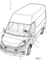
- the reference number 1 indicates a vehicle as a whole, in the non-limiting example illustrated herein a Light Commercial Vehicle, LCV, comprising, as is known, a frame (not shown for simplicity) and a plurality of panels 2 defining the body of the said vehicle 1.
- LCV Light Commercial Vehicle
- the vehicle 1 also comprises at least one air-bag system 3 of a known type and configured to expand and cushion impacts that may potentially cause damage to the driver or passenger.
- the vehicle 1 further comprises an electronic unit 4 configured to control a plurality of vehicle systems, including the above-mentioned air-bag system 3 and functional elements, not shown and configured to allow the operation of the vehicle, such as high voltage electrical equipment parts or control valves connected to the alternative fuel supply and distribution systems on board the vehicle.
- an electronic unit 4 configured to control a plurality of vehicle systems, including the above-mentioned air-bag system 3 and functional elements, not shown and configured to allow the operation of the vehicle, such as high voltage electrical equipment parts or control valves connected to the alternative fuel supply and distribution systems on board the vehicle.
- Figure 2 shows a panel 2 not making part of the present invention but useful for its understanding and comprising a body defining any substantially flat shape, i.e., with two dimensions much larger than the thickness of the said body.
- a parallelepiped portion is shown, for example, a body portion made of any shape and material, for example plastic.
- the panel 2 comprises a filament 5 made of electrically conductive material carried by the panel 2 and configured to break in case of impact and fracture of the panel 2.
- the filament 5 made of electrically conductive material is incorporated inside the body of the panel 2 so that it is not exposed to atmospheric agents and possible mechanical wear or abrasion. Even more advantageously, it is embedded in a plane corresponding to a neutral centre plane of the panel 2.
- Neutral plane refers to the plane in which the bending stresses on the panel 2 are the lowest (theoretically zero) with respect to a bending load imparted thereon.
- the filament 5 made of electrically conductive material enters through a first opening 6 inside the body of the panel 2 and exits therefrom through an opening 7 formed therein.
- the filament 5 made of electrically conductive material defines a path along the panel 2 so that it extends by at least twice the largest dimension of the panel 2.
- the filament 5 made of electrically conductive material defines a path extending far beyond twice the largest dimension of the panel 2, thereby providing a complex path to cover most of the surface defined by the panel 2.
- the filament 5 made of electrically conductive material defines a plurality of coils 5a parallel to the larger side of the panel 2.
- the plurality of coils 5a is embedded within the panel 2 between the first opening 6 and the second opening 7, which are positioned one below the other, respectively, and formed on the smaller edge of the panel 2.
- the path of the filament 5 made of electrically conductive material inside the panel 2 defines a "fork" shape due to the plurality of coils 5a connected, at one end and at the other, to the openings 6 and 7.
- connection means 8 here shown as holes 9, configured to allow the panel 2 to be connected to an element carried by the frame of the vehicle 1, for example by means of rivets or threaded elements.
- connection means 8 can be of any type, such as form-fit or snap-fit couplings.
- FIG 3 shows a panel 2 according to the invention that comprises the same elements as shown above in Figure 1 except for the below described ones.
- the body of the panel 2 defines at least one portion of reduced thickness 2a.
- this portion of reduced thickness 2a is a single, circular portion located at the geometric centre of the panel 2.
- the filament 5 made of electrically conductive material is also electrically connected to the electronic unit 4 and/or to the above-mentioned functional elements, i.e., for example, the high voltage electrical equipment parts or the control valves connected to the alternative fuel system.
- this electrical connection is made physically through an electrical connection outside the panel 2.
- the resistance of the filament 5 made of electrically conductive material will change, since the breakage of the panel 2 provides for the opening of the electric circuit formed by the filament 5 made of electrically conductive material and by the electronic unit 4 and/or the high voltage electrical equipment parts or the alternative fuel supply control valves.
- This change in electrical resistance will be processed by the electronic unit 4 to functionally insulate the electrical equipment parts or to insulate the alternative fuel flows. If the electrical connection is made directly by the electric filament with the functional elements of the vehicle, then this change in resistance will directly cause the insulation of the related potentially dangerous element.
- Figures 4 and 5 show a possible embodiment of a panel 2 according to the principles described above.
- the panel 2 comprises a body 101, and a cover 102 configured to wrap the body 101 and therefore having a shape such as to be form-fit coupled and fixed thereto in a known manner.
- the cover 102 can be made of high-density polyethylene or other plastic material with similar physical characteristics, and the body 101 can be made of expanded polypropylene (EPP).
- the body 101 is configured to define a seat 103 suitable to house the filament 5 made of electrically conductive material.
- the seat 103 is substantially rectangular and formed in the centre of the body 101.
- the cover 102 is coupled to the body 101, the seat 103 is obviously insulated with respect to the external environment.
- the filament 5 is made as a resistive-coated printed circuit board (PCB) 104 comprising a connector 105 configured to keep two input and output portions 104', 104" of the printed circuit board 104 separated and to connect them to the electronic unit 4 and/or to the above-mentioned functional elements.
- PCB printed circuit board
- the printed circuit board 104 may comprise portions of reduced thickness, or cuts, (not clearly shown) configured to facilitate the breaking of the printed circuit board 104 in the event of an impact.
- FIGS. 6 and 7 show a further embodiment of a panel 2 according to the principles described above.
- the panel 2 comprises a single pair of elements 202 made of high-density polyethylene, for example.
- Each element 201 is configured to define a first face 201a and a second face 201b opposite the first, therefore a face 201a facing outwards and a face 201b facing the inside of the vehicle.
- the two elements 201 are configured to be coupled on top of each other so that the inner face 201b of one element cooperates in contact with the outer face 201a of the other.
- the filament 5 is made by deposition of electrically conductive paint 202 on one of the faces 201a, 201b, in particular on the second, inner face 201b of one of the elements 201.
- the system of the sensorized panel 2 according to the invention allows the insulation of dangerous functional elements of the vehicle 1 to be released from the deployment of the air-bag system 3 of the vehicle.
- the system set out herein is particularly cost-effective and does not substantially increase the overall dimensions either outside or inside the vehicle 1.
- An effective example of this reduction is the use of an electrically conductive paint layer to define the filament 5.
- the filament 5 can be arranged in any way on the panel 2, or inside it, which can define different shapes and be made of different materials.
- the reduced-thickness portion 2a can be of a shape and number different from those described, just like the connection of the filament to the electronic unit 4 and/or to the functional elements of the vehicle 1.
- the shape defined by the body of the panel 2 and its position on the vehicle 1 can be any shape and position.
Landscapes
- Engineering & Computer Science (AREA)
- Automation & Control Theory (AREA)
- Mechanical Engineering (AREA)
- Air Bags (AREA)
Claims (9)
- Eine Verkleidung (2), die ausgeführt ist, einen Teil eines Fahrzeugs (1) abzudecken, wobei die Verkleidung (2) zumindest einen Körper (101, 102; 202) umfasst, der ausgeführt ist, mit einem Teil verbunden zu werden, der relativ zu einem Rahmen des Fahrzeugs (1) fixiert ist, wobei die Verkleidung (2) ein Filament (5) aus einem elektrisch leitendem Material umfasst, wobei das Filament (5) ausgeführt ist, elektrisch mit einem Funktionselement des Fahrzeugs (1) verbunden zu werden, wobei zumindest ein Körper (102) der Verkleidung (2) zumindest einen Bereich (2a) mit reduzierter Dicke im Vergleich zum restlichen Teil des Körpers (102) definiert,
dadurch gekennzeichnet, dass das Filament (5) einen Verlauf relativ zum Verkleidungskörper (2) definiert, wobei sich der Verlauf relativ zu dem Körper über den größten Teil der Oberfläche des zumindest einen Bereichs (2a) erstreckt und zumindest einen Bereich mit reduzierter Dicke im Vergleich zu den anderen verbleibenden Teilen des Filaments (5) umfasst. - Die Verkleidung nach Anspruch 1, wobei das Filament (5) in den Körper (101, 102) der Verkleidung (2) integriert ist.
- Die Verkleidung nach Anspruch 1 oder 2, wobei das Filament (5) in der neutralen Ebene der Verkleidung (2) angeordnet ist.
- Die Verkleidung nach einem der vorhergehenden Ansprüche, wobei das Filament (5) aus Metallmaterial besteht.
- Die Verkleidung nach einem der vorhergehenden Ansprüche, wobei das Filament (5) einen Verlauf relativ zum Verkleidungskörper (2) definiert, wobei sich der Verlauf in zumindest der doppelten Größe der größten Abmessung des Körpers im Raum erstreckt.
- Die Verkleidung nach einem der vorhergehenden Ansprüche, wobei das Filament (5) eine Leiterplatte (104) umfasst.
- Die Verkleidung nach einem der vorhergehenden Ansprüche, wobei das Filament (5) durch Auftragen von elektrisch leitfähiger Farbe (202) hergestellt ist.
- Ein Fahrzeug (1), umfassend zumindest eine Verkleidung (2) nach einem der vorhergehenden Ansprüche und funktionale Elemente, die elektrisch mit dem Filament (5) verbunden sind, sodass ein Bruch des Filaments (5) die funktionale Isolation dieser Elemente verursacht.
- Das Fahrzeug (1) nach Anspruch 8, umfassend eine elektronische Einheit (4), die elektrisch mit dem Filament (5) verbunden ist, sodass die Erkennung eines Bruchs des Filaments (5) von der elektronischen Einheit (4) verarbeitet wird, um die funktionalen Elemente so zu steuern, dass sie funktional isoliert werden.
Applications Claiming Priority (1)
| Application Number | Priority Date | Filing Date | Title |
|---|---|---|---|
| IT102020000005779A IT202000005779A1 (it) | 2020-03-18 | 2020-03-18 | Pannello sensorizzato per rilevazione di impatto in un veicolo |
Publications (3)
| Publication Number | Publication Date |
|---|---|
| EP3882086A1 EP3882086A1 (de) | 2021-09-22 |
| EP3882086B1 true EP3882086B1 (de) | 2024-12-18 |
| EP3882086C0 EP3882086C0 (de) | 2024-12-18 |
Family
ID=70805076
Family Applications (1)
| Application Number | Title | Priority Date | Filing Date |
|---|---|---|---|
| EP21163546.1A Active EP3882086B1 (de) | 2020-03-18 | 2021-03-18 | Sensorisierte platte zur erfassung eines aufpralls an einem fahrzeug |
Country Status (3)
| Country | Link |
|---|---|
| EP (1) | EP3882086B1 (de) |
| ES (1) | ES3010353T3 (de) |
| IT (1) | IT202000005779A1 (de) |
Families Citing this family (2)
| Publication number | Priority date | Publication date | Assignee | Title |
|---|---|---|---|---|
| DE102023112639A1 (de) * | 2023-05-12 | 2024-11-14 | Daimler Truck AG | Vorrichtung und Verfahren zur Durchführung einer Notabschaltung eines Hochvolt-Systems eines elektrisch angetriebenen Fahrzeugs |
| NL2034865B1 (en) * | 2023-05-19 | 2024-12-03 | Daf Trucks Nv | Skirt assembly for a BEV truck |
Family Cites Families (5)
| Publication number | Priority date | Publication date | Assignee | Title |
|---|---|---|---|---|
| JP2006240945A (ja) * | 2005-03-04 | 2006-09-14 | Nippon Sheet Glass Co Ltd | パネル |
| CN102210078B (zh) * | 2008-10-09 | 2014-10-29 | Adc电信公司 | 电力切换装置 |
| JP5183436B2 (ja) * | 2008-11-21 | 2013-04-17 | 株式会社日立製作所 | 機能性パネルおよびその接合方法 |
| JP5531626B2 (ja) * | 2009-05-26 | 2014-06-25 | 日産自動車株式会社 | 車両のバッテリアセンブリ冷却構造、および、ウォータージャケット付きバッテリアセンブリ |
| DE102015201440A1 (de) * | 2015-01-28 | 2016-07-28 | Bayerische Motoren Werke Aktiengesellschaft | Versorgungsschiene für ein Kraftfahrzeug |
-
2020
- 2020-03-18 IT IT102020000005779A patent/IT202000005779A1/it unknown
-
2021
- 2021-03-18 EP EP21163546.1A patent/EP3882086B1/de active Active
- 2021-03-18 ES ES21163546T patent/ES3010353T3/es active Active
Also Published As
| Publication number | Publication date |
|---|---|
| EP3882086A1 (de) | 2021-09-22 |
| IT202000005779A1 (it) | 2021-09-18 |
| ES3010353T3 (en) | 2025-04-02 |
| EP3882086C0 (de) | 2024-12-18 |
Similar Documents
| Publication | Publication Date | Title |
|---|---|---|
| US5645746A (en) | Use of PTC devices | |
| EP3882086B1 (de) | Sensorisierte platte zur erfassung eines aufpralls an einem fahrzeug | |
| EP1645475B1 (de) | Stromversorgungsvorrichtung für Fahrzeuge | |
| EP0638458B1 (de) | Elektrische Vorrichtung für ein Elektrofahrzeug | |
| US20210233729A1 (en) | Electrical circuit breaker | |
| US10964484B2 (en) | On-vehicle circuit unit | |
| US10663269B2 (en) | Initiator grounding clip | |
| EP0745515B1 (de) | Gerät zum Schaltkreisschutz in Kraftfahrzeug-Kabelbündeln | |
| US20150022931A1 (en) | Overcurrent protection apparatus | |
| US6283794B1 (en) | Connector for electrical fuse ignition device | |
| US7495880B2 (en) | Circuit board and electric device having circuit board | |
| KR102361583B1 (ko) | 자동차용 블럭 | |
| US10938142B2 (en) | Electrical connection box | |
| US6729907B1 (en) | Plug-in connector for an electrical device | |
| EP3509168B1 (de) | Drehbare verbindervorrichtung | |
| JPH08190809A (ja) | ヒューズ付き電線 | |
| EP1544570B1 (de) | Zünder | |
| KR100223470B1 (ko) | 다방향 충격 감지용 센서 | |
| KR102892526B1 (ko) | 파이로 퓨즈 | |
| US12109971B2 (en) | Conductive actuator housings and related airbag assemblies | |
| KR102730547B1 (ko) | 충격 시 릴레이 전원을 차단할 수 있는 배터리 팩 | |
| JP4194928B2 (ja) | 高感度ヒューズ | |
| JPH1118279A (ja) | 車載電気回路の短絡保護装置 | |
| US20080036474A1 (en) | Capacitive Transmitter Electrode | |
| CN119365955A (zh) | 用于保护电流回路的更换式过流防护装置、保险装置盒和交通工具 |
Legal Events
| Date | Code | Title | Description |
|---|---|---|---|
| PUAI | Public reference made under article 153(3) epc to a published international application that has entered the european phase |
Free format text: ORIGINAL CODE: 0009012 |
|
| STAA | Information on the status of an ep patent application or granted ep patent |
Free format text: STATUS: THE APPLICATION HAS BEEN PUBLISHED |
|
| AK | Designated contracting states |
Kind code of ref document: A1 Designated state(s): AL AT BE BG CH CY CZ DE DK EE ES FI FR GB GR HR HU IE IS IT LI LT LU LV MC MK MT NL NO PL PT RO RS SE SI SK SM TR |
|
| STAA | Information on the status of an ep patent application or granted ep patent |
Free format text: STATUS: REQUEST FOR EXAMINATION WAS MADE |
|
| 17P | Request for examination filed |
Effective date: 20220316 |
|
| RBV | Designated contracting states (corrected) |
Designated state(s): AL AT BE BG CH CY CZ DE DK EE ES FI FR GB GR HR HU IE IS IT LI LT LU LV MC MK MT NL NO PL PT RO RS SE SI SK SM TR |
|
| STAA | Information on the status of an ep patent application or granted ep patent |
Free format text: STATUS: EXAMINATION IS IN PROGRESS |
|
| 17Q | First examination report despatched |
Effective date: 20230411 |
|
| GRAP | Despatch of communication of intention to grant a patent |
Free format text: ORIGINAL CODE: EPIDOSNIGR1 |
|
| STAA | Information on the status of an ep patent application or granted ep patent |
Free format text: STATUS: GRANT OF PATENT IS INTENDED |
|
| INTG | Intention to grant announced |
Effective date: 20240715 |
|
| GRAS | Grant fee paid |
Free format text: ORIGINAL CODE: EPIDOSNIGR3 |
|
| GRAA | (expected) grant |
Free format text: ORIGINAL CODE: 0009210 |
|
| STAA | Information on the status of an ep patent application or granted ep patent |
Free format text: STATUS: THE PATENT HAS BEEN GRANTED |
|
| AK | Designated contracting states |
Kind code of ref document: B1 Designated state(s): AL AT BE BG CH CY CZ DE DK EE ES FI FR GB GR HR HU IE IS IT LI LT LU LV MC MK MT NL NO PL PT RO RS SE SI SK SM TR |
|
| REG | Reference to a national code |
Ref country code: CH Ref legal event code: EP |
|
| REG | Reference to a national code |
Ref country code: DE Ref legal event code: R096 Ref document number: 602021023419 Country of ref document: DE |
|
| REG | Reference to a national code |
Ref country code: IE Ref legal event code: FG4D |
|
| U01 | Request for unitary effect filed |
Effective date: 20241230 |
|
| U07 | Unitary effect registered |
Designated state(s): AT BE BG DE DK EE FI FR IT LT LU LV MT NL PT RO SE SI Effective date: 20250114 |
|
| REG | Reference to a national code |
Ref country code: ES Ref legal event code: FG2A Ref document number: 3010353 Country of ref document: ES Kind code of ref document: T3 Effective date: 20250402 |
|
| PG25 | Lapsed in a contracting state [announced via postgrant information from national office to epo] |
Ref country code: HR Free format text: LAPSE BECAUSE OF FAILURE TO SUBMIT A TRANSLATION OF THE DESCRIPTION OR TO PAY THE FEE WITHIN THE PRESCRIBED TIME-LIMIT Effective date: 20241218 |
|
| U20 | Renewal fee for the european patent with unitary effect paid |
Year of fee payment: 5 Effective date: 20250311 |
|
| PG25 | Lapsed in a contracting state [announced via postgrant information from national office to epo] |
Ref country code: NO Free format text: LAPSE BECAUSE OF FAILURE TO SUBMIT A TRANSLATION OF THE DESCRIPTION OR TO PAY THE FEE WITHIN THE PRESCRIBED TIME-LIMIT Effective date: 20250318 |
|
| PG25 | Lapsed in a contracting state [announced via postgrant information from national office to epo] |
Ref country code: GR Free format text: LAPSE BECAUSE OF FAILURE TO SUBMIT A TRANSLATION OF THE DESCRIPTION OR TO PAY THE FEE WITHIN THE PRESCRIBED TIME-LIMIT Effective date: 20250319 |
|
| PG25 | Lapsed in a contracting state [announced via postgrant information from national office to epo] |
Ref country code: RS Free format text: LAPSE BECAUSE OF FAILURE TO SUBMIT A TRANSLATION OF THE DESCRIPTION OR TO PAY THE FEE WITHIN THE PRESCRIBED TIME-LIMIT Effective date: 20250318 |
|
| PG25 | Lapsed in a contracting state [announced via postgrant information from national office to epo] |
Ref country code: SM Free format text: LAPSE BECAUSE OF FAILURE TO SUBMIT A TRANSLATION OF THE DESCRIPTION OR TO PAY THE FEE WITHIN THE PRESCRIBED TIME-LIMIT Effective date: 20241218 |
|
| PG25 | Lapsed in a contracting state [announced via postgrant information from national office to epo] |
Ref country code: PL Free format text: LAPSE BECAUSE OF FAILURE TO SUBMIT A TRANSLATION OF THE DESCRIPTION OR TO PAY THE FEE WITHIN THE PRESCRIBED TIME-LIMIT Effective date: 20241218 |
|
| PGFP | Annual fee paid to national office [announced via postgrant information from national office to epo] |
Ref country code: ES Payment date: 20250417 Year of fee payment: 5 |
|
| PG25 | Lapsed in a contracting state [announced via postgrant information from national office to epo] |
Ref country code: IS Free format text: LAPSE BECAUSE OF FAILURE TO SUBMIT A TRANSLATION OF THE DESCRIPTION OR TO PAY THE FEE WITHIN THE PRESCRIBED TIME-LIMIT Effective date: 20250418 |
|
| PG25 | Lapsed in a contracting state [announced via postgrant information from national office to epo] |
Ref country code: SK Free format text: LAPSE BECAUSE OF FAILURE TO SUBMIT A TRANSLATION OF THE DESCRIPTION OR TO PAY THE FEE WITHIN THE PRESCRIBED TIME-LIMIT Effective date: 20241218 |
|
| PG25 | Lapsed in a contracting state [announced via postgrant information from national office to epo] |
Ref country code: CZ Free format text: LAPSE BECAUSE OF FAILURE TO SUBMIT A TRANSLATION OF THE DESCRIPTION OR TO PAY THE FEE WITHIN THE PRESCRIBED TIME-LIMIT Effective date: 20241218 |
|
| PG25 | Lapsed in a contracting state [announced via postgrant information from national office to epo] |
Ref country code: MC Free format text: LAPSE BECAUSE OF FAILURE TO SUBMIT A TRANSLATION OF THE DESCRIPTION OR TO PAY THE FEE WITHIN THE PRESCRIBED TIME-LIMIT Effective date: 20241218 |
|
| PLBE | No opposition filed within time limit |
Free format text: ORIGINAL CODE: 0009261 |
|
| REG | Reference to a national code |
Ref country code: CH Ref legal event code: H13 Free format text: ST27 STATUS EVENT CODE: U-0-0-H10-H13 (AS PROVIDED BY THE NATIONAL OFFICE) Effective date: 20251024 |
|
| STAA | Information on the status of an ep patent application or granted ep patent |
Free format text: STATUS: NO OPPOSITION FILED WITHIN TIME LIMIT |
|
| 26N | No opposition filed |
Effective date: 20250919 |
|
| GBPC | Gb: european patent ceased through non-payment of renewal fee |
Effective date: 20250318 |
|
| PG25 | Lapsed in a contracting state [announced via postgrant information from national office to epo] |
Ref country code: GB Free format text: LAPSE BECAUSE OF NON-PAYMENT OF DUE FEES Effective date: 20250318 |
|
| PG25 | Lapsed in a contracting state [announced via postgrant information from national office to epo] |
Ref country code: CH Free format text: LAPSE BECAUSE OF NON-PAYMENT OF DUE FEES Effective date: 20250331 |
|
| PG25 | Lapsed in a contracting state [announced via postgrant information from national office to epo] |
Ref country code: IE Free format text: LAPSE BECAUSE OF NON-PAYMENT OF DUE FEES Effective date: 20250318 |
|
| U20 | Renewal fee for the european patent with unitary effect paid |
Year of fee payment: 6 Effective date: 20260203 |