EP3881749A1 - Haushaltsgerät, insbesondere wasserführendes haushaltsgerät - Google Patents
Haushaltsgerät, insbesondere wasserführendes haushaltsgerät Download PDFInfo
- Publication number
- EP3881749A1 EP3881749A1 EP21162786.4A EP21162786A EP3881749A1 EP 3881749 A1 EP3881749 A1 EP 3881749A1 EP 21162786 A EP21162786 A EP 21162786A EP 3881749 A1 EP3881749 A1 EP 3881749A1
- Authority
- EP
- European Patent Office
- Prior art keywords
- motor unit
- door
- appliance
- appliance door
- motor
- Prior art date
- Legal status (The legal status is an assumption and is not a legal conclusion. Google has not performed a legal analysis and makes no representation as to the accuracy of the status listed.)
- Granted
Links
Images




Classifications
-
- A—HUMAN NECESSITIES
- A47—FURNITURE; DOMESTIC ARTICLES OR APPLIANCES; COFFEE MILLS; SPICE MILLS; SUCTION CLEANERS IN GENERAL
- A47L—DOMESTIC WASHING OR CLEANING; SUCTION CLEANERS IN GENERAL
- A47L15/00—Washing or rinsing machines for crockery or tableware
- A47L15/42—Details
- A47L15/4251—Details of the casing
- A47L15/4257—Details of the loading door
-
- F—MECHANICAL ENGINEERING; LIGHTING; HEATING; WEAPONS; BLASTING
- F24—HEATING; RANGES; VENTILATING
- F24C—DOMESTIC STOVES OR RANGES ; DETAILS OF DOMESTIC STOVES OR RANGES, OF GENERAL APPLICATION
- F24C15/00—Details
- F24C15/02—Doors specially adapted for stoves or ranges
- F24C15/023—Mounting of doors, e.g. hinges, counterbalancing
-
- A—HUMAN NECESSITIES
- A47—FURNITURE; DOMESTIC ARTICLES OR APPLIANCES; COFFEE MILLS; SPICE MILLS; SUCTION CLEANERS IN GENERAL
- A47L—DOMESTIC WASHING OR CLEANING; SUCTION CLEANERS IN GENERAL
- A47L15/00—Washing or rinsing machines for crockery or tableware
- A47L15/42—Details
- A47L15/4251—Details of the casing
- A47L15/4257—Details of the loading door
- A47L15/4259—Arrangements of locking or security/safety devices for doors, e.g. door latches, switch to stop operation when door is open
-
- A—HUMAN NECESSITIES
- A47—FURNITURE; DOMESTIC ARTICLES OR APPLIANCES; COFFEE MILLS; SPICE MILLS; SUCTION CLEANERS IN GENERAL
- A47L—DOMESTIC WASHING OR CLEANING; SUCTION CLEANERS IN GENERAL
- A47L15/00—Washing or rinsing machines for crockery or tableware
- A47L15/42—Details
- A47L15/4251—Details of the casing
- A47L15/4257—Details of the loading door
- A47L15/4261—Connections of the door to the casing, e.g. door hinges
-
- D—TEXTILES; PAPER
- D06—TREATMENT OF TEXTILES OR THE LIKE; LAUNDERING; FLEXIBLE MATERIALS NOT OTHERWISE PROVIDED FOR
- D06F—LAUNDERING, DRYING, IRONING, PRESSING OR FOLDING TEXTILE ARTICLES
- D06F39/00—Details of washing machines not specific to a single type of machines covered by groups D06F9/00 - D06F27/00
- D06F39/12—Casings; Tubs
- D06F39/14—Doors or covers; Securing means therefor
Definitions
- the invention relates to a household appliance, in particular a water-bearing household appliance, such as a dishwasher, with an appliance housing providing an appliance space, which has a loading opening for access to the appliance space, with an appliance door rotatably mounted about a pivot axis for a closure of the loading opening, and with a motor device which is in operative connection with the appliance door and by means of which the appliance door can be moved from an open position into a closed position that closes the loading opening.
- a household appliance in particular a water-bearing household appliance, such as a dishwasher
- an appliance housing providing an appliance space, which has a loading opening for access to the appliance space
- an appliance door rotatably mounted about a pivot axis for a closure of the loading opening
- a motor device which is in operative connection with the appliance door and by means of which the appliance door can be moved from an open position into a closed position that closes the loading opening.
- Household appliances in general and water-bearing household appliances in particular are well known per se from the state of the art, which is why separate printed proof is not required at this point. It is therefore only an example of the DE 10 2017 218 501 A1 referenced, which discloses a generic household appliance in the embodiment of a dishwasher.
- a household appliance in the sense of the invention is in particular a water-conducting household appliance, such as a dishwasher, a washing machine and / or a dryer.
- the term "household appliance” also includes refrigerators, ovens, steamers, microwaves and / or the like.
- a household appliance of the generic type has an appliance housing that provides an appliance space.
- the device housing has a loading opening for user access to the device compartment.
- an appliance door is provided which is arranged on the appliance housing so that it can pivot about a pivot axis.
- the appliance door can be moved by the user from an open position into a closed position that closes the loading opening and vice versa.
- the closure of the loading opening by the appliance door in the closed position is preferably fluid-tight in the case of a water-bearing household appliance, for which purpose a A corresponding seal is provided between the appliance door and the appliance housing.
- FIG DE 10 2017 218 501 A1 the use of a motor device is known.
- the motor device is in operative connection with the appliance door and allows the appliance door to be moved from an open position into a closed position closing the loading opening after a previous activation by the user, and this without further manual intervention by the user.
- the construction according to the DE 10 2017 218 501 A1 has a cable drum that can be driven by the motor device and onto which a cable can be wound.
- This rope is arranged at one end on a lever on the appliance door. If the appliance door is in the open position, a motor-driven rotation of the rope drum causes the rope to wind up on the rope drum, as a result of which a tensile force is applied to the lever on the appliance door side, which in turn leads to a pivoting movement of the door into the locked position.
- a seal is provided between the appliance door and the loading opening in the closed position.
- the appliance door moves against this seal when it is moved into the closed position, and this with a certain force, so that the seal is squeezed between the appliance door and the appliance housing, which guarantees the sealing effect.
- an appropriately designed motor device is required, especially since the position of the device door-side lever, on which the cable is arranged on one end, becomes more unfavorable for a corresponding introduction of force as the door closes.
- the motor device to be dimensioned accordingly for proper door closure has proven to be disadvantageous.
- a correspondingly dimensioned motor device results in high costs.
- household appliances of the generic type usually do not have the installation space to accommodate such a motor device, so that either correspondingly complex redesigns are required or the use of such a motor device is simply not possible.
- the invention proposes a household appliance, in particular a dishwasher, of the type mentioned at the outset, which is characterized in that the motor device has a first motor unit and a second motor unit, the appliance door being moved from an open position to an open position by means of the first motor unit Intermediate position and by means of the second motor unit can be transferred from the intermediate position into the closed position closing the loading opening.
- the embodiment according to the invention is characterized by the interaction or the method of two motor units, both of which are intended to bring about a movement of the appliance door, but in doing so divide up the movement work for a door closing process. Accordingly, there are two closing phases. According to a first closing phase, the appliance door is moved from an open position into an intermediate position. According to a subsequent second closing phase, the appliance door is moved from the intermediate position into the closed position. The first motor unit works during the first closing phase, whereas the second motor unit works during the second closing phase.
- the advantage of this subdivision is that two comparatively inexpensive and compact motor units can be used. Because neither of the two motor units has to be designed in such a way that the appliance door of the household appliance, in particular the dishwasher, can be completely closed.
- the division of the closing process is such that the door is moved from an open position to an intermediate position by means of the first motor unit, the door already resting against the door seal in the intermediate position, i.e. the door is almost closed, squeezing or pressing the seal together is not effected by means of the first motor unit.
- the actual closing of the appliance door against the door sealing force then takes place exclusively by means of the second motor unit.
- a coupling device is provided which is arranged between the first motor unit and the appliance door and which is in operative connection on the drive side with the first motor unit and on the output side with the appliance door.
- This coupling device can, for example, serve to prevent trapping and / or enable the distinction between manual door closure and motor-driven door closure.
- the coupling device has a coupling which is designed to be switchable and can be transferred from a decoupled position to a coupled position and vice versa, the coupling being set up, in the case of operation of the first motor unit, one to effect automatic switching from the uncoupled position to the coupled position.
- the household appliance according to the invention has a coupling device with a coupling which is designed to be switchable.
- the coupling can be transferred from a decoupled position to a coupled position and vice versa.
- the uncoupled position the operative connection between the first motor unit and the appliance door is interrupted, which enables manual actuation of the appliance door, to be precise without the sluggishness operated by the first motor unit.
- the first motor unit does not rotate as a result of a manual pivoting movement of the appliance door.
- the coupling is in the coupled position, the operative connection between the first motor unit and the appliance door is closed, so that the appliance door can be driven by the first motor unit for transferring it to the intermediate position.
- the clutch is designed to bring about an automatic shift from the decoupled position into the coupled position when the first motor unit is operating.
- the coupling provided with the coupling device therefore ensures that when the first motor unit is activated, the coupling is automatically switched, which transfers it from the decoupled position to the coupled position will.
- the coupling is therefore basically in the uncoupled position, which enables manual door operation. If there is no manual actuation of the appliance door, but a motor-driven actuation of the appliance door, in particular for moving the appliance door into the intermediate position, no separate switching of the clutch is required for this. This is because this switches automatically, i.e. it is automatically transferred to the coupled position as soon as the first motor unit starts operating, i.e. the first motor unit is started by the user.
- This device of the clutch according to the invention essentially has two advantages.
- the user has the option of being able to differentiate between a manual and a motor-driven drive for the appliance door.
- the design of the coupling enables a motor-driven closing process of the appliance door to also be supported manually, in particular to be completed manually in order to accelerate the closing process. No further actuators are required for engaging or disengaging the clutch. This results solely as a function of the intended operation of the first motor unit.
- the appliance doors of previously known household appliances are typically operated by hand, both in terms of opening and in terms of closing. It is desirable that device doors can also be moved by a motor, in particular for the purpose of closing. For example, sensors are provided on the device to trigger such motor operation, so that a user can initiate motor operation with a simple movement of his hand or foot and thus initiate automatic door closure, also according to the previously known construction according to the DE 10 2017 218 501 A1 .
- the previously known construction has the disadvantage that manual door opening always has to take place against the motor force of the motor that is in operative connection with the appliance door. Even when the motor is at a standstill, the motor shaft must always be moved along with it, which requires a corresponding effort for manual opening.
- the construction according to the invention provides a remedy here, since the clutch is preferably basically in the uncoupled, ie uncoupled position, so that manual opening of the door does not lead to the motor shaft of the first motor unit rotating at the same time.
- the user automatically engages the clutch without further action, ie the clutch is transferred into the coupled position solely due to the motor rotating after it has been activated. This enables simple handling by the user without additional actuators for actuating the clutch.
- the clou according to the invention is, in particular, that the coupling only couples when the first motor unit is in rotary motion.
- the clutch does not engage, so that operation that is disconnected from the motor is possible.
- the clutch engages, so that a motorized movement then takes place.
- the operative connection between the first motor unit and the appliance door has a cable pull as a force transmission means.
- a cable pull enables motor-assisted closing of the appliance door.
- a motor-driven transfer of the appliance door into an open position is not provided according to this embodiment. The appliance door must therefore be opened manually, with the appliance door then being closed either manually or by a motor.
- a toothed belt or a chain can also be used as the power transmission means.
- the toothed belt or the chain is preferably motorized by means of a drive roller or a toothed wheel that is positively connected to the toothed belt or the chain.
- the force transmission means that is to say the cable pull, the toothed belt or the chain, is arranged on one end of a lever of the appliance door.
- the cable is put under tension. Since the power transmission means is arranged at one end on a lever of the appliance door, a torque acting on the appliance door is thereby generated, specifically about the pivot axis of the appliance door, as a result of which it closes a motor-driven door closure comes.
- the power transmission means is designed as a cable
- the cable is arranged on the other end of a rotatably mounted cable drum on which the cable can be at least partially wound.
- the first motor unit causes a twisting movement of the cable drum. This causes the cable pull to be wound onto the cable drum, the cable pull being under tensile stress in the manner already described, so that the appliance door swivels.
- the cable pull is unwound from the cable drum, with a spring return element acting on the cable drum preferably being provided so that the section of the cable pull unwound from the cable drum is always under a certain tensile prestress, so that in the event of operation the first motor unit is activated immediate response of the appliance door is ensured.
- the first motor unit is in operative connection with the cable drum, with the coupling device interposed, in order to cause the cable drum to rotate when the first motor unit is in operation.
- the cable pull is unwound from the cable drum when the door is opened and wound up again when the door is closed again without the motor shaft of the first motor unit rotating at the same time. If, however, the first motor unit is started with the appliance door open, the clutch engages and the cable drum is rotated by a motor, with the result that the appliance door is moved into the intermediate position by a motor. In this case, the cable pull is wound onto the cable drum when the device door is operated manually, in that the cable drum is rotated back into its starting position by the spring return means pretensioned as a result of a door opening.
- the power transmission means is designed as a toothed belt or chain
- the first motor unit is in operative connection with the drive roller or the gearwheel with the interposition of the coupling device in order to prevent the first motor unit from rotating when the first motor unit is in operation To effect drive roller or the gear.
- the toothed belt or the chain which is driven in this way by the first motor unit via the drive roller or the gearwheel, connects a spring element of the spring mechanism, which balances the weight of the appliance door, directly to the lever of the appliance door.
- the coupling has a rotating part which is arranged non-rotatably on a motor shaft of the first motor unit and which carries a clamping piece which is arranged thereon so as to be rotatable about a pivot axis.
- the coupling therefore has a rotating part. This sits on the motor shaft of the first motor unit, in a non-rotating manner. In the case of a motor-driven rotating movement of the motor shaft, the rotating part is consequently also rotated, specifically about the axis of rotation of the first motor unit provided by the motor shaft.
- the rotating part also carries a clamping piece which is arranged on the rotating part so as to be rotatable about a pivot axis. Two such clamping pieces are preferably provided. These can each rotate in relation to the rotating part, namely in a radial direction in relation to the rotating part from a retracted position to an extended position and vice versa.
- the clamping piece cooperates with an end section remote from the pivot axis with a link guide provided by a guide means.
- This slotted guide of the guide means causes the clamping piece interacting therewith to pivot in the radial direction with respect to the rotating part during operation.
- the clamping piece can have a pin engaging in the link guide of the guide means in its end section remote from the pivot axis. If the rotating part now rotates, the clamping piece rotates on the one hand together with the rotating part, specifically about the axis of rotation of the rotating part.
- the clamping piece executes a pivoting movement about its own pivot axis in relation to the rotating part, namely as a result of the guidance of the pin of the clamping piece remote from the pivot axis in the associated link guide of the guide means.
- the guide means is rotatably mounted on a bearing collar penetrated by the motor shaft, forming a friction fit.
- the formation of the friction seat on the bearing collar ensures that the guide means is not rotated when the rotating part is rotated, but the clamping piece carried by the rotating part has not yet moved into its end position in relation to the rotating part. Until this end position is reached, the guide means stands still in relation to the rotating part, which enables the end section of the clamping piece remote from the pivot axis to be guided along the associated link guide.
- the clamping piece As soon as the clamping piece is pivoted into its end position in relation to the rotating part, it takes the guide means with it, so that it rotates together with the rotating part with the mechanical interposition of the clamping piece.
- the guide means is rotatably mounted on the bearing collar. The formation of the friction fit between the bearing collar and the guide means therefore does not prevent the guide means from twisting along with it, but merely ensures that the clamping piece rotates in relation to the rotating part until the clamping piece has reached its end position, which corresponds to the link guide.
- the coupling has a coupling housing which at least partially accommodates the rotating part and which has an inner contour which interacts with the clamping piece.
- the rotating part is arranged at least in sections within a coupling housing. In the case of a clamping piece that is not pivoted in relation to the rotating part, the rotating part is freely rotatable with respect to the coupling housing. There is therefore no power transmission between the rotating part and the clutch housing.
- the clutch housing has an inner contour that interacts with the clamping piece.
- the clamping piece engages in the inner contour of the coupling housing as soon as the clamping piece has pivoted in relation to the rotating part and is in its extended end position. In this position of the clamping piece, there is preferably a form fit between the clamping piece and the inner contour of the coupling housing, so that torque is transmitted from the rotating part to the coupling housing by means of the clamping piece.
- the coupling is coupled, that is to say it is in its coupled position, so that a power transmission from the motor-driven rotating part to the coupling housing can take place.
- the inner contour has a receiving groove or trough configured to correspond to the end section of the clamping piece remote from the pivot axis.
- the clamping piece engages in this receiving groove with the formation of a form fit when the clamping piece has pivoted in relation to the rotating part and is in its end position.
- the rotating part rotates with respect to the coupling housing, so that no power can be transmitted from the first motor unit to the coupling housing. Only when the clamping piece engages positively in the associated receiving recess of the clutch housing is a force fit so that a motor torque can be transmitted to the clutch housing.
- the clutch housing provides an output shaft. This is in operative connection with the cable drum, so that when the clutch is engaged, the cable drum can be driven by a motor.
- the construction of the clutch described above allows an automatic shifting of the clutch to take place as soon as the first motor unit starts up. This is because an operation of the first motor unit means that the rotating part of the coupling rotates, and thus the clamping piece also rotates in relation to the rotating part. As soon as the rotating part is rotated by a certain angular amount about the axis of rotation of the first motor unit provided by the motor shaft, the clamping piece has reached its end position, which is rotated relative to the rotating part, and engages in an associated receiving recess of the coupling housing. As a result, there is a frictional connection, so that the motor-generated torque is transferred to the clutch housing and thus to the drive shaft and ultimately to the cable drum coupled to it.
- the coupling housing may rotate faster than the motor-driven rotating part, depending on the manual application of force. This then leads to an automatic uncoupling, since in the case of a faster rotating coupling housing that of a receiving recess recorded clamping piece is released from the receiving trough. Manual intervention on the part of the user therefore does not lead to a force being applied to the first motor unit, but to automatic decoupling, since the positive fit between the clamping piece and the coupling housing is canceled when the coupling housing rotates faster, i.e. at a higher speed than the motor-driven rotating part of the Coupling. A "pushing" of the appliance door by the user is therefore protected by the embodiment according to the invention and does not lead to damage to either the coupling or the first motor unit.
- the construction according to the invention thus proves to be robust and safe to handle in everyday practical use.
- the coupling device has a second coupling which is designed as an overload coupling.
- This second coupling is used, in particular for safety reasons, to prevent trapping and prevents the door from closing if the door is blocked.
- the second coupling has a first coupling part and a second coupling part, the second coupling part resting against the first coupling part under spring preload.
- the two coupling parts are in operative connection, which is achieved in that the first coupling part is designed to be stationary and the second coupling part presses against the first coupling part in a spring-loaded manner.
- the torque provided by the first motor unit is transmitted from the first coupling part to the second coupling part, so that a power transmission from the first motor unit to the cable drum to be rotated can take place in the manner already described.
- the first motor unit works against the resulting resistance. As soon as the resistance is too high, the spring preload on the clutch side is no longer sufficient to press the second clutch part onto the first clutch part in a force-transmitting manner. When the power is interrupted, the coupling parts slip through, which prevents the appliance door from being closed any further, with the result that it is reliably prevented from becoming trapped in the door gap.
- the first coupling part is arranged on the output shaft of the first coupling in a rotationally fixed manner. Accordingly, it is provided that the first motor unit is followed by the first clutch and then the second clutch. As an alternative to this, the arrangement is reversed, in which the first motor unit is followed by the second clutch and then the first clutch.
- the advantage of the first alternative embodiment is that the second clutch can be set to be much more sensitive and the resistance at which the second clutch slips can be specified much more precisely.
- the second clutch is a claw clutch.
- the operative connection between the second motor unit and the appliance door has a linearly displaceable rack.
- the appliance door located in an intermediate position is gripped by means of this toothed rack and then moved into the closed position by a subsequent movement.
- the rack has a locking bolt on the device side which interacts with a door lock of the device door.
- the locking block of the rack is used for releasable but secure locking with the appliance door, so that it can be pressed against the appliance seal for a transfer from the intermediate position to the closed position and brought into the final closed position against the seal door forces.
- the toothed rack can be transferred from a retracted closed position into an extended open position and vice versa by means of the second motor unit.
- the toothed rack To move the appliance door into the closed position, the toothed rack must first of all be extended by means of the second motor unit and brought into its open position. In this position, a connection can take place between the locking block on the rack side and the door lock.
- This connection is achieved in that the appliance door is brought into the intermediate position by means of the first motor unit, as a result of which it with its The door lock opens onto the rack on the locking latch side.
- there is an automatic latching between the rack and the appliance door As soon as this connection between the appliance door and the rack is closed, the rack is moved back into its closed position. The rack takes the appliance door with it until it is locked.
- the appliance door is brought into an intermediate position when it is moved from an open position into a closed position that closes the loading opening.
- the transfer of the appliance door into the intermediate position is brought about solely by the first motor unit.
- the subsequent transfer of the appliance door from the intermediate position to the closed position is carried out by the second motor unit.
- a toothed rack interacting with the appliance door is moved linearly by means of the second motor unit, the toothed rack first being extended into an open position and then being moved back into a closed position.
- the rack is extended followed by the rack retracting.
- the extension serves to couple the rack to the appliance door or to bring the rack into a position in which it can be coupled to the appliance door.
- the appliance door can be moved into the locked position by retracting the rack.
- the two Motor units are initially operated simultaneously for a limited period of time.
- the simultaneous operation of the two motor units is provided so that the appliance door is moved from an open position to the intermediate position by means of the first motor unit.
- the second motor unit is operated to extend the rack, ie to move the rack into the open position, in which a coupling with the appliance door is possible.
- the second motor unit is switched off before the appliance door reaches the intermediate position. This is preferably provided because the operation of the first motor unit for moving the appliance door into the intermediate position takes longer than moving the rack into the open position by means of the second motor unit.
- the second motor unit switches on (or switched on again) and the first motor unit is switched off when the appliance door is in the intermediate position.
- the first closing phase is complete.
- the first motor unit can then be switched off. It takes over the second motor unit in that the rack is driven and brought into its closed position by means of the second motor unit.
- the invention is characterized overall by a device, on the one hand, and a method, on the other hand, which enable a door-closing process to be carried out in two phases by means of two motor units.
- the appliance door is transferred to an intermediate position by means of the first motor unit. Starting from this intermediate position, the appliance door is then transferred into its closed position by means of the second motor unit.
- a coupling device is also provided which is assigned to the first motor unit and, on the one hand, provides anti-jamming protection and, on the other hand, effects automatic coupling if the door is not closed manually, but by means of a motor.
- the rack is not extended by means of the second motor unit. Starting the second motor unit to move the rack is only possible with a motor-driven one Door closure required, which is why the second motor unit starts only when the first motor unit is started.
- the second motor unit is started every time the door is opened, both automatically and manually, and the rack is thus extended.
- the user only needs to manually close the door from the open position to the intermediate position.
- this triggers an automatic start of the second motor unit, for example via a switch or the like, which moves the rack together with the appliance door into the closed position.
- This also makes manual door closing considerably easier, since the user does not have to overcome any door sealing forces when closing the door.
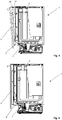
- Fig. 1 shows a household appliance according to the invention using the example of a dishwasher 1 in a schematic perspective illustration.
- the dishwasher 1 has an outer housing (not shown in more detail in the figures) which houses the device housing 2.
- the device housing 2 provides a device compartment 3 which is accessible via a loading opening 4.
- the dishwasher 1 also has an appliance door 5 which is mounted so as to be rotatable about a pivot axis and which is used to close the loading opening 4.
- the appliance door 5 can be moved from a closed position that closes the loading opening 4 into an open position and vice versa.
- Fig. 1 shows the appliance door 5 in an open position in which the loading opening 4 is partially open. The same shows Fig. 3 in a side view.
- Fig. 2 shows a fully opened appliance door 5, on the other hand
- Fig. 5 shows the closed position of the appliance door 5.
- Fig. 4 an intermediate position of the appliance door 5 is shown.
- the appliance door 5 has a lever 6 arranged thereon near the pivot axis.
- a lever 6 is provided on each side of the appliance door 5.
- a toothed belt 7 is arranged on one end of a respective lever 6, which is guided over a deflection roller 8 and a tensioning roller 9 and on the other end is arranged on a spring element which is stationary with respect to the device housing 2.
- This spring element 18 is not shown in any more detail in the drawings and is partially formed by the sheet metal section 10 covered.
- the toothed belt 7 arranged on the levers 6 is subjected to tensile stress, which leads to tensioning of the spring element arranged on the other end of the respective toothed belt 7 and thus to a braking of the appliance door 5.
- This force stored in the spring elements is released again when the appliance door 5 is moved into the closed position, which enables the appliance door 5 to be closed more easily.
- the dishwasher 1 also has a first motor unit 11, which is in operative connection with the appliance door 5 and by means of which the appliance door 5 is moved from an open position, as shown, for example, in FIG Fig. 2 is shown in an intermediate position according to Fig. 4 is transferable.
- the first motor unit 11 drives the deflection roller 8, which is in positive engagement with the toothed belt 7.
- a motor-driven rotation of the deflection roller 8 consequently leads to tensile stress on the toothed belt 7, as a result of which force is applied to the appliance door 5, with the result that it rotates clockwise in the direction of the loading opening 4.
- the dishwasher 1 also has a second motor unit 13. This is arranged on the top of the device housing 2 on the device housing 2. Like, in particular, a synopsis of the Figures 6 to 9 can be seen, the second motor unit 13 interacts with a toothed rack 14 with the interposition of a toothed wheel 17. Depending on the direction of rotation of the motor unit 13, the rack 14 can either be extended into an open position or retracted into a closed position.
- Fig. 6 shows the open position of the rack 14, on the other hand
- Fig. 9 shows the closed position of the rack 14.
- the toothed rack 14 On the device door side, the toothed rack 14 has a locking block 15 which interacts with a door lock 16 on the device door side.
- the appliance door 5 can be carried along when the rack 14 is moved back into the closed position, specifically up to the closed position of the appliance door 5, as shown in the sequence of figures in FIG Figures 6 to 9 reveals.
- the inventive Dishwasher via a motor device which has a first motor unit 11 and a second motor unit 13.
- the appliance door 5 can be moved from an open position into an intermediate position by means of the first motor unit 11. Another movement of the appliance door 5, ie a movement of the appliance door 5 from the intermediate position to the closed position, then takes place by means of the second motor unit 13.
- the door closing process is therefore divided into two phases, the door closing in the first phase by the first motor unit 11 and the door closing in the second phase by the second motor unit 13.
- the embodiment described above makes it possible to dimension the first motor unit 11 smaller than is known per se from the prior art. This is because the first motor unit 11 does not have to be designed in such a way that it is possible to work on the appliance door 5 against the sealing forces caused by the seal 12. This is because the appliance door 5 is only moved into the intermediate position by means of the first motor unit, in which the appliance door 5 can already rest against the seal 12, but the seal 12 has not yet been compressed. The actual closing of the appliance door 5 with the compression of the seal 12 then takes place by means of the second motor unit 13.
- the embodiment according to the invention proves to be particularly advantageous when the dishwasher 1 already has a second motor unit 13 including a toothed rack 14 for the purpose of opening the door gap for a steam extraction.
- Diagram a) shows the door position over time. At t 0 the door is open and the start command for the two motor units 11 and 13 is given. The door is then closed up to time t 4 , at which time the door is completely closed, that is to say the door has reached its locked position.
- Diagram b) shows the operation of the first motor unit 11. This is started at time t 0 , so that the appliance door 5 moves. The first motor unit 11 is operated until time t 3 . At time t 3 , the appliance door 5 has reached its intermediate position.
- Diagram c) shows the operation of the second motor unit 13. This is operated at time t 0 , specifically in a first direction of movement up to time t 1 . This causes the rack 14 to extend. From time t 1 to time t 3, the motor unit 13 is switched off. It is then switched on again, specifically in the opposite direction of rotation, so that the toothed rack 14 cooperating with it is retracted. The motor unit 13 is operated between times t 3 and t 4 , ie from the intermediate position of the appliance door 5 to its closed position at time t 4 .
- Diagram d shows the position of the toothed rack 14. This is in its retracted closed position at time t 0. It is extended as a result of operation of the second motor unit 13 and reaches its extended open position at time t 1. The motor unit 13 is switched off so that the rack remains in this position until time t 3. As soon as the appliance door 5 reaches its intermediate position at t 3 , there is a coupling between the rack 14 and the appliance door 5. The first motor unit 11 is switched off and the second motor unit 13 is started, so that the rack 14 is retracted again, namely in the time period t 3 to t 4 according to diagram d).
- Diagram e shows a door lock switch present in the door lock 16. This is activated by catching the locking pin 15 on the rack side, to be precise at time t 3 . The second motor unit 13 then switches and retracts the rack 14 with the result that the door closes. The door lock switch remains switched until the appliance door 5 is opened manually, as can be seen from diagram e).
Landscapes
- Engineering & Computer Science (AREA)
- Chemical & Material Sciences (AREA)
- Combustion & Propulsion (AREA)
- Mechanical Engineering (AREA)
- General Engineering & Computer Science (AREA)
- Power-Operated Mechanisms For Wings (AREA)
Abstract
Description
- Die Erfindung betrifft ein Haushaltsgerät, insbesondere ein wasserführendes Haushaltsgerät, wie zum Beispiel eine Geschirrspülmaschine, mit einem einen Geräteraum bereitstellenden Gerätegehäuse, das für einen Zugriff auf den Geräteraum eine Beschickungsöffnung aufweist, mit einer um eine Schwenkachse verdrehbar gelagerten Gerätetür für einen Verschluss der Beschickungsöffnung, und mit einer Motoreinrichtung, die in Wirkverbindung mit der Gerätetür steht und mittels welcher die Gerätetür aus einer Offenstellung in eine die Beschickungsöffnung verschließende Verschlussstellung überführbar ist.
- Haushaltsgeräte im Allgemeinen sowie wasserführende Haushaltsgeräte im Speziellen sind aus dem Stand der Technik an sich gut bekannt, weshalb es eines gesonderten druckschriftlichen Nachweises an dieser Stelle nicht bedarf. Es sei deshalb auch nur beispielhaft auf die
DE 10 2017 218 501 A1 verwiesen, die ein gattungsgemäßes Haushaltsgerät in der Ausgestaltung einer Geschirrspülmaschine offenbart. - Ein Haushaltsgerät im Sinne der Erfindung ist insbesondere ein wasserführendes Haushaltsgerät, wie zum Beispiel eine Geschirrspülmaschine, eine Waschmaschine und/oder ein Trockner. Unter den Begriff "Haushaltsgerät" fallen aber auch Kühlschränke, Backöfen, Dampfgarer, Mikrowellen und/oder dgl.
- Ein gattungsgemäßes Haushaltsgerät verfügt über ein Gerätegehäuse, das einen Geräteraum bereitstellt. Für einen verwenderseitigen Zugriff auf den Geräteraum weist das Gerätegehäuse eine Beschickungsöffnung auf.
- Für einen Verschluss der Beschickungsöffnung im Verwendungsfall des Haushaltsgeräts ist eine Gerätetür vorgesehen, die um eine Schwenkachse verschwenkbar am Gerätegehäuse angeordnet ist. Im bestimmungsgemäßen Verwendungsfall kann die Gerätetür verwenderseitig aus einer Offenstellung in eine die Beschickungsöffnung verschließende Verschlussstellung und umgekehrt überführt werden. Der Verschluss der Beschickungsöffnung durch die Gerätetür in Verschlussstellung ist im Falle eines wasserführenden Haushaltsgerätes bevorzugterweise fluiddicht, zu welchem Zweck eine entsprechende Dichtung zwischen Gerätetür und Gerätegehäuse vorgesehen ist.
- Um zumindest eine Verschwenkbewegung der Gerätetür aus einer Offenstellung in eine die Beschickungsöffnung verschließende Verschlussstellung zu vereinfachen, ist aus der
DE 10 2017 218 501 A1 die Verwendung einer Motoreinrichtung bekannt. Die Motoreinrichtung steht in Wirkverbindung mit der Gerätetür und gestattet es, die Gerätetür nach einer vorherigen verwenderseitigen Aktivierung aus einer Offenstellung in eine die Beschickungsöffnung verschließende Verschlussstellung zu überführen, und dies ohne weiteren manuellen Eingriff durch den Verwender. - Die Konstruktion nach der
DE 10 2017 218 501 A1 verfügt über eine mittels der Motoreinrichtung antreibbare Seiltrommel, auf die ein Seil aufwickelbar ist. Dieses Seil ist einendseitig an einem Hebel der Gerätetür angeordnet. Befindet sich die Gerätetür in Offenstellung, so wird durch ein motorangetriebenes Verdrehen der Seiltrommel bewirkt, dass sich das Seil auf die Seiltrommel aufwickelt, infolge dessen es zu einer Zugkraftbeaufschlagung des gerätetürseitigen Hebels kommt, was wiederum zu einer Verschwenkbewegung der Tür bis in die Verschlussstellung führt. Um in der Verschlussstellung der Gerätetür ein fluiddichtes Verschließen der Beschickungsöffnung zu gewährleisten, ist eine in Verschlussstellung zwischen Gerätetür und Beschickungsöffnung angeordnete Dichtung vorgesehen. Gegen diese Dichtung fährt die Gerätetür bei einer Überführung in die Verschlussstellung an, und dies mit einer gewissen Kraft, so dass es zu einem die Dichtwirkung garantierenden Einquetschen der Dichtung zwischen der Gerätetür und dem Gerätegehäuse kommt. Um diese Türdichtungskraft zu überwinden, bedarf es einer entsprechend ausgelegten Motoreinrichtung, zumal die Stellung des gerätetürseitigen Hebels, an dem der Seilzug einendseitig angeordnet ist, mit zunehmender Türschließung für eine entsprechende Krafteinleitung ungünstiger wird. - Die für eine ordnungsgemäße Türschließung entsprechend zu dimensionierende Motoreinrichtung hat sich als nachteilig erwiesen. Zum einen ergeben sich für eine entsprechend dimensionierte Motoreinrichtung hohe Kosten. Zum anderen ist bei gattungsgemäßen Haushaltsgeräten zumeist nicht der Bauraum zur Unterbringung einer solchen Motoreinrichtung vorhanden, so dass es entweder entsprechend aufwendiger Umkonstruktionen bedarf oder der Einsatz einer solchen Motoreinrichtung schlichtweg nicht möglich ist.
- Es ist deshalb die Aufgabe der Erfindung, ein Haushaltsgerät der eingangs genannten Art vorzuschlagen, das konstruktiv die voraufgeführten Nachteile zu überwinden vermag.
- Zur Lösung dieser Aufgabe wird mit der Erfindung ein Haushaltsgerät, insbesondere eine Geschirrspülmaschine, der eingangs genannten Art vorgeschlagen, das sich dadurch auszeichnet, dass die Motoreinrichtung eine erste Motoreinheit und eine zweite Motoreinheit aufweist, wobei die Gerätetür mittels der ersten Motoreinheit aus einer Offenstellung in eine Zwischenstellung und mittels der zweiten Motoreinheit aus der Zwischenstellung in die die Beschickungsöffnung verschließende Verschlussstellung überführbar ist.
- Die erfindungsgemäße Ausgestaltung zeichnet sich durch das Zusammenspiel bzw. das Verfahren von zwei Motoreinheiten aus, die beide dafür vorgesehen sind, eine Bewegung der Gerätetür zu bewirken, sich dabei aber die Bewegungsarbeit für einen Türschließvorgang aufteilen. Es ergeben sich dementsprechend zwei Schließphasen. Gemäß einer ersten Schließphase wird die Gerätetür aus einer Offenstellung in eine Zwischenstellung überführt. Gemäß einer sich daran anschließenden zweiten Schließphase erfolgt eine Bewegung der Gerätetür aus der Zwischenstellung in die Verschlussstellung. Während der ersten Schließphase arbeitet die erste Motoreinheit, wohingegen während der zweiten Schließphase die zweite Motoreinheit arbeitet.
- Von Vorteil dieser Unterteilung ist, dass zwei vergleichsweise preisgünstige und kompakt ausgebildete Motoreinheiten zum Einsatz kommen können. Denn keine der beiden Motoreinheiten muss für sich derart ausgelegt sein, eine Komplettschließung der Gerätetür des Haushaltsgeräts, insbesondere der Geschirrspülmaschine, bewirken zu können. Dabei ist die Unterteilung des Schließvorgangs derart, dass mittels der ersten Motoreinheit die Tür aus einer Offenstellung in eine Zwischenstellung überführt wird, wobei die Tür in der Zwischenstellung bereits an der Türdichtung anliegt, die Tür also fast geschlossen ist, ein Zusammenquetschen oder-drücken der Dichtung mittels der ersten Motoreinheit aber nicht bewirkt wird. Das eigentliche Schließen der Gerätetür gegen die Türdichtungskraft erfolgt dann ausschließlich mittels der zweiten Motoreinheit.
- Im Ergebnis der erfindungsgemäßen Ausgestaltung ist eine motorbetriebene Türschließung ermöglicht, wobei die zum Einsatz kommenden Motoreinheiten jeweils im Unterschied zum Stand der Technik kleiner dimensioniert sind, was zum einen aus Kostengründen aber auch aufgrund des nur geringen Einbauraums von Vorteil ist.
- Es ist gemäß einem weiteren Merkmal der Erfindung eine zwischen erster Motoreinheit und Gerätetür angeordnete Kupplungseinrichtung vorgesehen, die antriebsseitig mit der ersten Motoreinheit und abtriebsseitig mit der Gerätetür in Wirkverbindung steht. Diese Kupplungseinrichtung kann beispielsweise dem Einklemmschutz dienen und/oder die Unterscheidung zwischen einer manuellen Türschließung und einer motorangetriebenen Türschließung ermöglichen.
- Es ist in diesem Zusammenhang gemäß einem weiteren Merkmal der Erfindung vorgesehen, dass die Kupplungseinrichtung eine Kupplung aufweist, die schaltbar ausgebildet ist und aus einer entkuppelten Stellung in eine gekuppelte Stellung und umgekehrt überführbar ist, wobei die Kupplung eingerichtet ist, im Betriebsfall der ersten Motoreinheit eine automatische Schaltung aus der entkuppelten Stellung in die gekuppelte Stellung zu bewirken.
- Demgemäß verfügt das erfindungsgemäße Haushaltsgerät über eine Kupplungseinrichtung mit einer Kupplung, die schaltbar ausgebildet ist. Dabei kann die Kupplung aus einer entkuppelten Stellung in eine gekuppelte Stellung und umgekehrt überführt werden. In der entkuppelten Stellung ist die Wirkverbindung zwischen der ersten Motoreinheit und der Gerätetür unterbrochen, was eine manuelle Betätigung der Gerätetür ermöglicht, und zwar ohne eine durch die erste Motoreinheit bediente Schwergängigkeit. Denn dank der Entkupplung dreht die erste Motoreinheit infolge einer manuellen Verschwenkbewegung der Gerätetür nicht mit.
- Befindet sich die Kupplung indes in gekuppelter Stellung, so ist die Wirkverbindung zwischen erster Motoreinheit und Gerätetür geschlossen, so dass ein Antrieb der Gerätetür zur Überführung in die Zwischenstellung durch die erste Motoreinheit erfolgen kann.
- Die Kupplung ist eingerichtet, um im Betriebsfall der ersten Motoreinheit eine automatische Schaltung aus der entkuppelten Stellung in die gekuppelte Stellung zu bewirken. Die mit der Kupplungseinrichtung vorgesehene Kupplung sorgt mithin dafür, dass es bei einer Aktivierung der ersten Motoreinheit zu einer automatischen Schaltung der Kupplung kommt, wobei diese aus der entkuppelten Stellung in die gekuppelte Stellung überführt wird.
- Die Kupplung befindet sich mithin grundsätzlich in entkuppelter Stellung, was eine manuelle Türbetätigung ermöglicht. Soll nun insbesondere zum Überführen der Gerätetür in die Zwischenstellung kein manuelles, sondern ein motorangetriebenes Betätigen der Gerätetür stattfinden, so bedarf es hierfür keiner separaten Schaltung der Kupplung. Denn diese schaltet automatisch, wird also automatisch in die gekuppelte Stellung überführt, sobald der Betriebsfall der ersten Motoreinheit einsetzt, d.h. die erste Motoreinheit verwenderseitig gestartet wird.
- Diese erfindungsgemäße Einrichtung der Kupplung erbringt im Wesentlichen zwei Vorteile. Zum einen ist die verwenderseitig gegebene Möglichkeit geschaffen, zwischen einem manuellen und einem motorangetriebenen Antrieb der Gerätetür wahlweise unterscheiden zu können. Insbesondere ist es möglich, die Gerätetür entweder manuell oder motorangetrieben in ihre Zwischenstellung zu überführen. Des Weiteren ermöglicht es die Kupplungsausgestaltung, dass ein motorangetriebener Schließvorgang der Gerätetür auch manuell unterstützt, insbesondere zur Beschleunigung des Schließvorgangs auch manuell zu Ende geführt werden kann. Dabei wird zur Einkupplung oder Auskupplung der Kupplung keine weitere Aktorik benötigt. Dies ergibt sich allein in Abhängigkeit eines bestimmungsgemäßen Betriebs der ersten Motoreinheit.
- Die Gerätetüren vorbekannter Haushaltsgeräte werden typischerweise per Hand bedient, und zwar sowohl hinsichtlich eines Öffnens als auch hinsichtlich eines Schließens. Es ist gewünscht, dass Gerätetüren auch motorisch verfahren werden können, insbesondere zum Zwecke der Schließung. Für die Auslösung eines solchen Motorbetriebs sind beispielsweise Sensoren am Gerät vorgesehen, so dass ein Verwender durch eine einfache Bewegung mit der Hand oder dem Fuß den Motorbetrieb auslösen und somit eine automatische Türschließung einleiten kann, so auch gemäß der vorbekannten Konstruktion nach der
DE 10 2017 218 501 A1 . - Die vorbekannte Konstruktion hat allerdings den Nachteil, dass eine manuelle Türöffnung immer entgegen der Motorkraft des in Wirkverbindung mit der Gerätetür stehenden Motors zu erfolgen hat. Auch bei stillstehendem Motor muss immer die Motorwelle mitbewegt werden, was entsprechenden Kraftaufwand bei einem manuellen Öffnen erforderlich macht. Die erfindungsgemäße Konstruktion schafft hier Abhilfe, da sich die Kupplung vorzugsweise grundsätzlich in entkuppelter, d.h. ausgekuppelter Stellung befindet, so dass ein manuelles Öffnen der Tür nicht zu einem mitverdrehen der Motorwelle der ersten Motoreinheit führt. Bei einem nachfolgenden Schließen der Gerätetür durch Motorkraft erfolgt ohne weiteres Hinzutun durch den Verwender ein automatisches Einkuppeln der Kupplung, d.h. ein Überführen der Kupplung in die gekuppelte Stellung allein aufgrund des sich nach vorheriger Aktivierung drehenden Motors. Dies ermöglicht eine verwenderseitig einfache Handhabung ohne zusätzliche Aktuatoren zur Betätigung der Kupplung.
- Der erfindungsgemäße Clou besteht insbesondere darin, dass die Kupplung nur dann kuppelt, wenn die erste Motoreinheit in Drehbewegung ist. Es ist mithin eine Art Freilaufkupplung gegeben. Wenn ein manueller Betrieb stattfindet, die erste Motoreinheit also nicht aktiv ist, greift die Kupplung nicht, so dass ein vom Motor losgekuppelter Betrieb möglich ist. Sobald sich aber der Verwender dafür entscheidet, wahlweise den Motorbetrieb einzuschalten, greift die Kupplung, so dass dann ein motorisches Verfahren erfolgt.
- Gemäß einem weiteren Merkmal der Erfindung ist vorgesehen, dass die Wirkverbindung zwischen erster Motoreinheit und Gerätetür einen Seilzug als Kraftübertragungsmittel aufweist. Ein solcher Seilzug ermöglicht ein motorunterstütztes Schließen der Gerätetür. Ein motorangetriebenes Überführen der Gerätetür in eine Offenstellung ist gemäß dieser Ausführungsform nicht vorgesehen. Ein Öffnen der Gerätetür hat mithin manuell stattzufinden, wobei dann ein Schließen der Gerätetür wahlweise manuell oder motorgetrieben erfolgt.
- Alternativ zu einem Seilzug kann auch ein Zahnriemen oder eine Kette als Kraftübertragungsmittel eingesetzt werden. In diesem Fall erfolgt bevorzugterweise ein Motorantrieb des Zahnriemens oder der Kette mittels einer mit dem Zahnriemen oder der Kette in formschlüssiger Verbindung stehender Antriebsrolle bzw. eines Zahnrades.
- Gemäß einem weiteren Merkmal der Erfindung ist vorgesehen, dass das Kraftübertragungsmittel, also der Seilzug, dem Zahnriemen oder der Kette, einendseitig an einem Hebel der Gerätetür angeordnet ist. Im Betriebsfall der ersten Motoreinheit wird der Seilzug unter Zugspannung gesetzt. Da das Kraftübertragungsmittel einendseitig an einem Hebel der Gerätetür angeordnet ist, wird hierdurch ein auf die Gerätetür einwirkendes Drehmoment erzeugt, und zwar um die Schwenkachse der Gerätetür, infolge dessen es zu einer motorangetriebenen Türschließung kommt.
- Für den Fall, dass das Kraftübertragungsmittel als Seilzug ausgebildet ist, ist gemäß einem weiteren Merkmal vorgesehen, dass der Seilzug anderendseitig an einer verdrehbar gelagerten Seiltrommel angeordnet ist, auf die der Seilzug zumindest teilweise aufwickelbar ist. Im bestimmungsgemäßen Verwendungsfall erfolgt durch die erste Motoreinheit eine Verdrehbewegung der Seiltrommel. Dies bewirkt ein Aufwickeln des Seilzugs auf die Seiltrommel, wobei der Seilzug in schon vorbeschriebener Weise unter Zugspannung steht, so dass es zu einer Verschwenkbewegung der Gerätetür kommt. Bei einem manuellen Öffnen der Gerätetür wird der Seilzug von der Seiltrommel abgewickelt, wobei bevorzugterweise ein auf die Seiltrommel einwirkendes Federrückstellelement vorgesehen ist, so dass der von der Seiltrommel abgewickelte Abschnitt des Seilzugs stets unter einer gewissen Zugvorspannung steht, so dass im Betriebsfall der ersten Motoreinheit ein sofortiges Ansprechen der Gerätetür sichergestellt ist.
- Es ist gemäß einem weiteren Merkmal der Erfindung vorgesehen, dass die erste Motoreinheit unter Zwischenschaltung der Kupplungseinrichtung in Wirkverbindung mit der Seiltrommel steht, um im Betriebsfall der ersten Motoreinheit ein Verdrehen der Seiltrommel zu bewirken.
- Bei einer rein manuellen Betätigung der Gerätetür wird der Seilzug von der Seiltrommel bei einem Öffnen der Tür abgewickelt und bei einem erneuten Schließen der Tür wieder aufgewickelt, ohne dass es zu einer Mitverdrehung der Motorwelle der ersten Motoreinheit kommt. Wird indes bei geöffneter Gerätetür die erste Motoreinheit gestartet, so kuppelt die Kupplung ein und es erfolgt ein motorangetriebenes Verdrehen der Seiltrommel mit der Folge, dass ein Überführen der Gerätetür in die Zwischenstellung motorangetrieben stattfindet. Dabei erfolgt ein Aufwickeln des Seilzugs auf die Seiltrommel bei einer manuellen Gerätetürbedienung dadurch, dass die Seiltrommel durch das infolge einer Türöffnung vorgespannte Federrückstellmittel zurück in ihre Ausgangsposition verdreht wird.
- Für den Fall, dass das Kraftübertragungsmittel als Zahnriemen oder Kette ausgebildet ist, ist gemäß einem weiteren Merkmal vorgesehen, dass die erste Motoreinheit unter Zwischenschaltung der Kupplungseinrichtung in Wirkverbindung mit der Antriebsrolle bzw. des Zahnrades steht, um im Betriebsfall der ersten Motoreinheit ein Verdrehen der Antriebsrolle bzw. des Zahnrades zu bewirken. Dabei verbindet der auf diese Weise durch die erste Motoreinheit über die Antriebsrolle bzw. das Zahnrad angetriebene Zahnriemen oder die Kette ein Federelement der Federmechanik, welche für den Gewichtsausgleich der Gerätetür sorgt, unmittelbar mit dem Hebel der Gerätetür.
- Gemäß einem besonderen Merkmal der Erfindung ist vorgesehen, dass die Kupplung ein verdrehfest auf einer Motorwelle der ersten Motoreinheit angeordnetes Drehteil aufweist, das ein um eine Schwenkachse verdrehbar daran angeordnetes Klemmstück trägt. Die Kupplung verfügt mithin über ein Drehteil. Dieses sitzt auf der Motorwelle der ersten Motoreinheit, und zwar verdrehfest. Bei einer motorangetriebenen Verdrehbewegung der Motorwelle kommt es mithin auch zu einem Verdrehen des Drehteils, und zwar um die von der Motorwelle bereitgestellte Drehachse der ersten Motoreinheit.
- Das Drehteil trägt ferner ein Klemmstück, das um eine Schwenkachse verdrehbar am Drehteil angeordnet ist. Bevorzugterweise sind zwei solcher Klemmstücke vorgesehen. Diese können jeweils in Relation zum Drehteil verdrehen, und zwar in einer in Relation zum Drehteil radialen Richtung aus einer eingefahrenen Stellung in eine ausgefahrene Stellung und umgekehrt.
- Gemäß einem weiteren Merkmal der Erfindung ist vorgesehen, dass das Klemmstück mit einem schwenkachsenentfernten Endabschnitt mit einer von einem Führungsmittel bereitgestellten Kulissenführung zusammenwirkt. Diese Kulissenführung des Führungsmittels bedingt im Betriebsfall ein Verschwenken des damit zusammenwirkenden Klemmstücks in radialer Richtung zum Drehteil. Zu diesem Zweck kann das Klemmstück in seinem schwenkachsenentfernten Endabschnitt über einen in die Kulissenführung des Führungsmittels eingreifenden Zapfen verfügen. Kommt es nun zu einer Verdrehbewegung des Drehteils, so verdreht das Klemmstück einerseits zusammen mit dem Drehteil, und zwar um die Drehachse des Drehteils. Gleichzeitig vollführt das Klemmstück in Relation zum Drehteil eine Verschwenkbewegung um die eigene Schwenkachse, und zwar infolge der Führung des schwenkachsenentfernten Zapfens des Klemmstücks in der zugehörigen Kulissenführung des Führungsmittels.
- Gemäß einem weiteren Merkmal der Erfindung ist vorgesehen, dass das Führungsmittel auf einem von der Motorwelle durchragten Lagerbund unter Ausbildung eines Reibsitzes verdrehbar gelagert ist.
- Durch die Ausbildung des Reibsitzes auf dem Lagerbund ist sichergestellt, dass das Führungsmittel reibbelastet nicht mitverdreht, wenn das Drehteil verdreht, das vom Drehteil getragene Klemmstück aber noch nicht in seine in Relation zum Drehteil ausgelangte Endposition verfahren ist. Bis zur Erreichung dieser Endposition steht das Führungsmittel in Relation zum Drehteil still, was die Führung des schwenkachsenentfernten Endabschnittes des Klemmstückes entlang der zugehörigen Kulissenführung ermöglicht.
- Sobald das Klemmstück in Relation zum Drehteil in seine Endposition verschwenkt ist, nimmt es das Führungsmittel mit, so dass dieses zusammen mit dem Drehteil unter mechanischer Zwischenordnung des Klemmstücks mitverdreht. Um dies zu ermöglichen, ist das Führungsmittel auf dem Lagerbund verdrehbar gelagert. Die Ausbildung des Reibsitzes zwischen Lagerbund und Führungsmittel verhindert mithin nicht eine Mitnahmeverdrehbewegung des Führungsmittels, sondern stellt lediglich sicher, dass eine Verdrehbewegung des Klemmstücks in Relation zum Drehteil stattfindet, bis das Klemmstück seine in Entsprechung der Kulissenführung vorgegebene Endposition erreicht hat.
- Gemäß einem weiteren Merkmal der Erfindung ist vorgesehen, dass die Kupplung ein das Drehteil zumindest teilweise aufnehmendes Kupplungsgehäuse aufweist, das eine mit dem Klemmstück zusammenwirkende Innenkontur aufweist. Das Drehteil ist zumindest abschnittsweise innerhalb eines Kupplungsgehäuses angeordnet. Bei einem nicht in Relation zum Drehteil verschwenkten Klemmstück ist das Drehteil gegenüber dem Kupplungsgehäuse frei verdrehbar. Eine Kraftübertragung zwischen Drehteil und Kupplungsgehäuse findet mithin nicht statt.
- Das Kupplungsgehäuse weist eine Innenkontur auf, die mit dem Klemmstück zusammenwirkt. Dabei greift das Klemmstück in die Innenkontur des Kupplungsgehäuses ein, sobald sich das Klemmstück in Relation zum Drehteil verschwenkt hat und sich in seiner ausgefahrenen Endposition befindet. In dieser Position des Klemmstücks findet vorzugsweise ein Formschluss zwischen Klemmstück und Innenkontur des Kupplungsgehäuses statt, so dass mittels des Klemmstücks eine Drehmomentübertragung vom Drehteil auf das Kupplungsgehäuse stattfindet. In dieser Position des Klemmstücks ist die Kupplung eingekuppelt, befindet sich also in ihrer gekuppelten Stellung, so dass eine Kraftübertragung von dem motorangetriebenen Drehteil auf das Kupplungsgehäuse stattfinden kann.
- Gemäß einem weiteren Merkmal der Erfindung ist vorgesehen, dass die Innenkontur eine zum schwenkachsenentfernten Endabschnitt des Klemmstücks korrespondierend ausgebildete Aufnahmenut, oder -mulde aufweist. In diese Aufnahmenut greift das Klemmstück unter Ausbildung eines Formschlusses ein, wenn sich das Klemmstück in Relation zum Drehteil verschwenkt hat und sich in seiner Endposition befindet. So lange diese Position des Klemmstücks noch nicht erreicht ist, dreht das Drehteil gegenüber dem Kupplungsgehäuse durch, so dass keine Kraftübertragung von der ersten Motoreinheit auf das Kupplungsgehäuse stattfinden kann. Erst wenn das Klemmstück formschlüssig in die zugehörige Aufnahmemulde des Kupplungsgehäuses eingreift, ist ein Kraftschluss gegeben, so dass ein Motordrehmoment auf das Kupplungsgehäuse übertragen werden kann.
- Gemäß einem weiteren Merkmal der Erfindung ist vorgesehen, dass das Kupplungsgehäuse eine Abtriebswelle bereitstellt. Diese steht in Wirkverbindung mit der Seiltrommel, so dass bei eingekuppelter Kupplung ein Motorantrieb der Seiltrommel stattfinden kann.
- Die Konstruktion der vorbeschriebenen Kupplung gestattet es, dass ein automatisches Schalten der Kupplung stattfindet, sobald die erste Motoreinheit anfährt. Denn ein Betrieb der ersten Motoreinheit bedingt, dass sich das Drehteil der Kupplung verdreht, und damit auch eine Verdrehung des Klemmstücks in Relation zum Drehteil stattfindet. Sobald das Drehteil um einen gewissen Winkelbetrag um die durch die Motorwelle bereitgestellte Drehachse der ersten Motoreinheit verdreht ist, hat das Klemmstück seine gegenüber dem Drehteil verdrehte Endposition erreicht und greift in eine zugehörige Aufnahmemulde des Kupplungsgehäuses ein. Hierdurch bedingt ist Kraftschluss gegeben, so dass ein Übertrag des motorgenerierten Drehmoments auf das Kupplungsgehäuse und damit auf die Antriebswelle und schlussendlich auf die damit gekoppelte Seiltrommel stattfindet.
- Wird nun trotz motorangetriebener Schließung der Gerätetür manuell nachgeholfen, indem verwenderseitig die Gerätetür manuell nachgeführt wird, so verdreht je nach manueller Kraftbeaufschlagung das Kupplungsgehäuse unter Umständen schneller als das motorangetriebene Drehteil. Dies führt dann zu einem automatischen Entkuppeln, da bei einem schneller verdrehenden Kupplungsgehäuse das von einer Aufnahmemulde aufgenommene Klemmstück von der Aufnahmemulde freigegeben wird. Ein verwenderseitiger manueller Eingriff führt mithin nicht zu einer Kraftbeaufschlagung der ersten Motoreinheit, sondern zu einem automatischen Entkuppeln, da der Formschluss zwischen Klemmstück, und Kupplungsgehäuse aufgehoben wird, wenn das Kupplungsgehäuse durch den manuellen Verwendereingriff schneller, d.h. mit höherer Drehzahl dreht als das motorangetriebene Drehteil der Kupplung. Ein "Anschieben" der Gerätetür durch den Verwender ist mithin durch die erfindungsgemäße Ausgestaltung abgesichert und führt nicht zu einer Beschädigung weder der Kupplung, noch der ersten Motoreinheit. Damit erweist sich die erfindungsgemäße Konstruktion im alltäglichen Praxiseinsatz als robust und handhabungssicher.
- Gemäß einem weiteren Merkmal der Erfindung ist vorgesehen, dass die Kupplungseinrichtung eine zweite Kupplung aufweist, die als Überlastkupplung ausgebildet ist. Diese zweite Kupplung dient insbesondere aus Sicherheitsgründen dem Einklemmschutz und vermeidet eine Türschließung bei einer Blockade der Tür.
- Gemäß einem weiteren Merkmal der Erfindung ist vorgesehen, dass die zweite Kupplung ein erstes Kupplungsteil und ein zweites Kupplungsteil aufweist, wobei das zweite Kupplungsteil unter Federvorspannung am ersten Kupplungsteil anliegt. Im Normalfall sind die beiden Kupplungsteile in Wirkverbindung, was dadurch erreicht ist, dass das erste Kupplungsteil feststehend ausgebildet ist und das zweite Kupplungsteil federbelastet gegen das erste Kupplungsteil drückt. Im Betriebsfall wird das von der ersten Motoreinheit bereitgestellte Drehmoment vom ersten Kupplungsteil auf das zweite Kupplungsteil übertragen, so dass in schon vorbeschriebener Weise eine Kraftübertragung von der ersten Motoreinheit auf die zu verdrehende Seiltrommel stattfinden kann.
- Kommt es zu einer Blockade der Tür, beispielsweise dadurch, dass ein Körperteil des Verwenders in den Türschlitz zwischen der sich schließenden Tür einerseits und dem Gerätegehäuse andererseits gerät, so arbeitet die erste Motoreinheit gegen den sich hierdurch ergebenden Widerstand an. Sobald der Widerstand zu hoch ist, reicht die kupplungsseitige Federvorspannung nicht mehr aus, um das zweite Kupplungsteil kraftübertragend an das erste Kupplungsteil anzudrücken. Es kommt unter Kraftunterbrechung zu einem Durchrutschen der Kupplungsteile, was ein weiteres Schließen der Gerätetür mit dem Erfolg unterbindet, dass ein Einklemmen im Türspalt sicher verhindert ist.
- Gemäß einem weiteren Merkmal der Erfindung ist vorgesehen, dass das erste Kupplungsteil verdrehfest auf der Abtriebswelle der ersten Kupplung angeordnet ist. Demgemäß ist vorgesehen, dass sich an die erste Motoreinheit zunächst die erste Kupplung und alsdann die zweite Kupplung anschließt. Alternativ hierzu ist eine umgekehrte Anordnung, dergemäß sich an die erste Motoreinheit zunächst die zweite Kupplung und alsdann die erste Kupplung anschließt.
- Von Vorteil der ersten alternativen Ausgestaltung ist, dass die zweite Kupplung sehr viel sensibler eingestellt und der Widerstand, bei dem es zu einem Durchrutschen der zweiten Kupplung kommt, sehr viel genauer vorgegeben werden kann.
- Bei der zweiten Kupplung handelt es sich gemäß einem weiteren Merkmal der Erfindung um eine Klauenkupplung.
- Gemäß einem weiteren Merkmal der Erfindung ist vorgesehen, dass die Wirkverbindung zwischen der zweiten Motoreinheit und der Gerätetür eine linear verfahrbare Zahnstange aufweist. Mittels dieser Zahnstange wird die sich in einer Zwischenstellung befindliche Gerätetür ergriffen und durch anschließendes Verfahren in die Verschlussstellung überführt.
- Die Zahnstange verfügt zu diesem Zweck gemäß einem weiteren Merkmal der Erfindung geräteseitig über einen Schließkloben, der mit einem Türschloss der Gerätetür zusammenwirkt. Der Schließkloben der Zahnstange dient der lösbaren, aber sicheren Verrastung mit der Gerätetür, so dass diese für eine Überführung aus der Zwischenstellung in die Verschlussstellung an die Gerätedichtung angedrückt und gegen die Dichtungstürkräfte in die endgültige Verschlussstellung gebracht werden kann.
- Gemäß einem weiteren Merkmal der Erfindung ist vorgesehen, dass die Zahnstange mittels der zweiten Motoreinheit aus einer eingefahrenen Schließstellung in eine ausgefahrene Offenstellung und umgekehrt überführbar ist. Für ein Überführen der Gerätetür in die Verschlussstellung ist die Zahnstange also zunächst einmal mittels der zweiten Motoreinheit auszufahren und in ihre Offenstellung zu bringen. In dieser Stellung kann eine Verbindung zwischen zahnstangenseitigem Schließkloben und Türschloss stattfinden. Diese Verbindung wird dadurch erreicht, dass die Gerätetür mittels der ersten Motoreinheit in die Zwischenstellung verbracht wird, infolge dessen sie mit ihrem Türschloss auf die Zahnstange schließklobenseitig auffährt. Es kommt infolge dessen zu einer automatischen Verrastung zwischen Zahnstange und Gerätetür. Sobald diese Verbindung zwischen Gerätetür und Zahnstange geschlossen ist, wird die Zahnstange zurückverfahren in ihre Schließstellung. Dabei nimmt die Zahnstange die Gerätetür bis in ihre Verschlussstellung mit.
- Mit der Erfindung wird zur Lösung der vorstehenden Aufgabe ferner vorgeschlagen ein Verfahren zur motorbetriebenen Überführung einer Gerätetür eines Haushaltsgerätes der vorbeschriebenen Art auf einer Offenstellung in eine Verschlussstellung, bei dem die Gerätetür mittels einer ersten Motoreinheit aus der Offenstellung in eine Zwischenstellung und mittels einer zweiten Motoreinheit aus der Zwischenstellung in die Verschlussstellung überführt wird.
- Gemäß der erfindungsgemäßen Verfahrensdurchführung ist vorgesehen, dass die Gerätetür bei der Überführung aus einer Offenstellung in eine die Beschickungsöffnung verschließende Verschlussstellung in eine Zwischenstellung gebracht wird. Dabei wird die Überführung der Gerätetür in die Zwischenstellung allein durch die erste Motoreinheit bewirkt. Die sich dann anschließende Überführung der Gerätetür aus der Zwischenstellung in die Verschlussstellung erfolgt durch die zweite Motoreinheit. Es ist mithin ein zweiphasiger Bewegungsvorgang gegeben, wobei sich die beiden Motoreinheiten den Schließvorgang aufteilen und die erste Motoreinheit für die erste Schließphase und die zweite Motoreinheit für die zweite Schließphase zuständig ist. Eine solche Verfahrensdurchführung erbringt die schon vorstehend erläuterten Vorteile.
- Gemäß einem weiteren Merkmal der Erfindung ist vorgesehen, dass mittels der zweiten Motoreinheit eine mit der Gerätetür zusammenwirkende Zahnstange linear verfahren wird, wobei die Zahnstange zunächst in einer Offenstellung ausgefahren und anschließend in eine Schließstellung zurückverfahren wird. Während eines Schließvorgangs erfolgt demnach ein Ausfahren der Zahnstange gefolgt von einem Einfahren der Zahnstange. Dabei dient das Ausfahren dazu, die Zahnstange mit der Gerätetür zu koppeln bzw. die Zahnstange in eine Stellung zu verbringen, in der die Kopplung mit der Gerätetür möglich ist. Sobald die Kopplung erfolgt ist, kann durch ein Einfahren der Zahnstange ein Überführen der Gerätetür in die Verschlussstellung erfolgen.
- Gemäß einem weiteren Merkmal der Erfindung ist vorgesehen, dass die beiden Motoreinheiten zu Beginn für eine begrenzte Zeitdauer zeitgleich betrieben werden. Der zeitgleiche Betrieb der beiden Motoreinheiten ist vorgesehen, damit mittels der ersten Motoreinheit die Gerätetür ausgehend von einer Offenstellung in die Zwischenstellung überführt wird. Während dieser Zeit wird die zweite Motoreinheit betrieben, um die Zahnstange auszufahren, d.h. um die Zahnstange in die Offenstellung zu bewegen, in welcher eine Verkupplung mit der Gerätetür ermöglicht ist.
- Gemäß einem weiteren Merkmal der Erfindung ist vorgesehen, dass die zweite Motoreinheit abgeschaltet wird, bevor die Gerätetür die Zwischenstellung erreicht. Dies ist bevorzugterweise deshalb vorgesehen, weil der Betrieb der ersten Motoreinheit zur Überführung der Gerätetür in die Zwischenstellung länger andauert, als die Zahnstange mittels der zweiten Motoreinheit in die Offenstellung zu verbringen.
- Gemäß einem weiteren Merkmal der Erfindung ist vorgesehen, dass die zweite Motoreinheit einschaltet (oder wieder eingeschaltet) und die erste Motoreinheit abgeschaltet wird, wenn sich die Gerätetür in der Zwischenstellung befindet.
- Sobald die Gerätetür mit der ersten Motoreinheit in eine Zwischenstellung verbracht ist, ist die erste Schließphase abgeschlossen. Die erste Motoreinheit kann dann abgeschaltet werden. Es übernimmt die zweite Motoreinheit, indem die Zahnstange angetrieben und in ihre Schließstellung mittels der zweiten Motoreinheit verbracht wird.
- Die Erfindung zeichnet sich insgesamt durch eine Vorrichtung einerseits und ein Verfahren andererseits aus, die es ermöglichen, einen Türschließvorgang mittels zweier Motoreinheiten zweiphasig abzuwickeln. Dabei erfolgt eine Überführung der Gerätetür in eine Zwischenstellung mittels der ersten Motoreinheit. Mittels der zweiten Motoreinheit erfolgt dann ausgehend von dieser Zwischenstellung eine Überführung der Gerätetür in ihre Verschlussstellung.
- Erfindungsgemäß ist des Weiteren eine Kupplungseinrichtung vorgesehen, die der ersten Motoreinheit zugeordnet ist und zum einen Klemmschutz bereitstellt sowie zum anderen ein automatisches Kuppeln bewirkt, falls eine Türschließung nicht manuell, sondern motorisch durchgeführt wird. Dabei findet im Falle einer manuellen Türschließung kein Ausfahren der Zahnstange mittels der zweiten Motoreinheit statt. Das Starten der zweiten Motoreinheit zur Bewegung der Zahnstange ist nur bei einer motorgetriebenen Türschließung erforderlich, weshalb die zweite Motoreinheit nur dann startet, wenn die erste Motoreinheit gestartet wird.
- Alternativ kann auch vorgesehen sein, dass die zweite Motoreinheit bei jeder Türöffnung, sowohl bei automatischer als auch bei manueller Türöffnung, gestartet und damit die Zahnstange ausgefahren wird. In diesem Fall muss ein manuelles Türschließen vom Benutzer lediglich von der Offenstellung in die Zwischenstellung betrieben werden. Sobald die Gerätetür in die Zwischenstellung gebracht ist und die Gerätetür mit der Zahnstange verrastet, löst dies, etwa über einen Schalter o.ä., ein automatisches Starten der zweiten Motoreinheit aus, welche die Zahnstange zusammen mit der Gerätetür in die Schließstellung verfährt. Hierdurch wird auch das manuelle Türschließen erheblich erleichtert, da vom Benutzer keine Türdichtungskräfte beim Schließen der Tür überwunden werden müssen.
- Weitere Merkmale und Vorteile der Erfindung ergeben sich aus der nachfolgenden Beschreibung anhand der Figuren. Dabei zeigen
- Fig. 1
- in schematischer perspektivischer Darstellung ein erfindungsgemäßes Haushaltsgerät am Beispiel einer Haushaltsgeschirrspülmaschine, wobei sich die Gerätetür in einer teilgeöffneten Stellung befindet;
- Fig. 2
- in einer schematischen Seitenansicht die Geschirrspülmaschine nach
Fig. 1 mit sich in Offenstellung befindlicher Gerätetür; - Fig. 3
- in schematischer Seitenansicht die Geschirrspülmaschine nach
Fig. 1 mit sich in teilgeöffneter Stellung befindlicher Gerätetür; - Fig. 4
- in schematischer Seitenansicht die Geschirrspülmaschine nach
Fig. 1 mit sich in einer Zwischenstellung befindlicher Gerätetür; - Fig. 5
- in schematischer Seitenansicht die Geschirrspülmaschine nach
Fig. 1 mit sich in Verschlussstellung befindlicher Gerätetür; - Fig. 6
- in schematischer Schnittdarstellung ausschnittsweise die Geschirrspülmaschine nach
Fig. 1 mit teilgeöffneter Gerätetür; - Fig. 7
- in schematischer Schnittdarstellung ausschnittsweise die Geschirrspülmaschine nach
Fig. 1 mit noch nicht gekoppelter Zahnstange; - Fig. 8
- in schematischer Schnittdarstellung ausschnittsweise die Geschirrspülmaschine nach
Fig. 1 mit gekuppelter Zahnstange; - Fig. 9
- in schematischer Schnittdarstellung ausschnittsweise die Geschirrspülmaschine nach
Fig. 1 mit sich in Verschlussstellung befindlicher Gerätetür; und - Fig. 10
- eine mehrere Diagramme umfassende Diagrammdarstellung.
-
Fig. 1 lässt in schematisch perspektivischer Darstellung ein erfindungsgemäßes Haushaltsgerät am Beispiel einer Geschirrspülmaschine 1 erkennen. - Die Geschirrspülmaschine 1 verfügt über ein in den Figuren nicht näher dargestelltes Außengehäuse, das das Gerätegehäuse 2 beherbergt. Dabei stellt das Gerätegehäuse 2 einen Geräteraum 3 bereit, der über eine Beschickungsöffnung 4 zugänglich ist.
- Die Geschirrspülmaschine 1 verfügt des Weiteren über eine um eine Schwenkachse verdrehbar gelagerte Gerätetür 5, die dem Verschluss der Beschickungsöffnung 4 dient. Dabei kann die Gerätetür 5 aus einer die Beschickungsöffnung 4 verschließenden Verschlussstellung in eine Offenstellung und umgekehrt überführt werden.
Fig. 1 zeigt die Gerätetür 5 in einer Offenstellung, in der die Beschickungsöffnung 4 teilgeöffnet ist. Selbiges zeigtFig. 3 in einer Seitenansicht.Fig. 2 zeigt eine vollständig geöffnete Gerätetür 5, wohingegenFig. 5 die Verschlussstellung der Gerätetür 5 zeigt. InFig. 4 ist eine Zwischenstellung der Gerätetür 5 dargestellt. - Wie eine Zusammenschau der
Figuren 1 bis 5 erkennen lässt, verfügt die Gerätetür 5 schwenkachsennah über einen daran angeordneten Hebel 6. Dabei ist je Seite der Gerätetür 5 ein Hebel 6 vorgesehen. - An einem jeweiligen Hebel 6 ist einendseitig ein Zahnriemen 7 angeordnet, der über eine Umlenkrolle 8 und eine Spannrolle 9 geführt und anderendseitig an einem gegenüber dem Gerätegehäuse 2 stationären Federelement angeordnet ist. Dieses Federelement 18 ist in den Zeichnungen nicht näher dargestellt und durch den Blechabschnitt 10 teilweise verdeckt.
- Bei einer manuellen Öffnung der Gerätetür 5 durch einen Verwender wird der an den Hebeln 6 jeweils angeordnete Zahnriemen 7 auf Zug beansprucht, was zu einem Spannen des anderendseitig am jeweiligen Zahnriemen 7 angeordneten Federelements und damit zu einem Bremsen der Gerätetür 5 führt. Diese in den Federelementen gespeicherte Kraft wird bei einem Überführen der Gerätetür 5 in die Verschlussstellung wieder freigesetzt, was ein vereinfachtes Schließen der Gerätetür 5 ermöglicht.
- Die Geschirrspülmaschine 1 verfügt des Weiteren über eine erste Motoreinheit 11, die in Wirkverbindung mit der Gerätetür 5 steht und mittels welcher die Gerätetür 5 aus einer Offenstellung, wie sie beispielsweise in
Fig. 2 gezeigt ist, in eine Zwischenstellung gemäßFig. 4 überführbar ist. Die erste Motoreinheit 11 treibt zu diesem Zweck die Umlenkrolle 8 an, die mit dem Zahnriemen 7 formschlüssig in Eingriff steht. Ein motorangetriebenes Verdrehen der Umlenkrolle 8 führt mithin zu einer Zugbeanspruchung des Zahnriemens 7, infolge dessen es zu einer Kraftbeaufschlagung der Gerätetür 5 mit dem Ergebnis kommt, dass diese im Uhrzeigersinn in Richtung auf die Beschickungsöffnung 4 verdreht. - Die Geschirrspülmaschine 1 verfügt des Weiteren über eine zweite Motoreinheit 13. Diese ist oberseitig des Gerätegehäuses 2 am Gerätegehäuse 2 angeordnet. Wie insbesondere eine Zusammenschau der
Figuren 6 bis 9 erkennen lässt, wirkt die zweite Motoreinheit 13 unter Zwischenordnung eines Zahnrades 17 mit einer Zahnstange 14 zusammen. Je nach Drehrichtung der Motoreinheit 13 kann die Zahnstange 14 entweder in eine Offenstellung ausgefahren oder in eine Schließstellung eingefahren werden.Fig. 6 zeigt die Offenstellung der Zahnstange 14, wohingegenFig. 9 die Schließstellung der Zahnstange 14 zeigt. - Die Zahnstange 14 verfügt gerätetürseitig über einen Schließkloben 15, der mit einem gerätetürseitigen Türschloss 16 zusammenwirkt. Bei einer Verrastung von Schließkloben 15 und Türschloss 16 kann bei einem Zurückverfahren der Zahnstange 14 in die Schließstellung die Gerätetür 5 mitgenommen werden, und zwar bis in die Verschlussstellung der Gerätetür 5, wie dies die Figurenabfolge der
Figuren 6 bis 9 erkennen lässt. - Wie sich aus der vorstehenden Darstellung ergibt, verfügt die erfindungsgemäße Geschirrspülmaschine über eine Motoreinrichtung, die eine erste Motoreinheit 11 und eine zweite Motoreinheit 13 aufweist. Dabei kann die Gerätetür 5 mittels der ersten Motoreinheit 11 aus einer Offenstellung in eine Zwischenstellung überführt werden. Ein weiteres Verfahren der Gerätetür 5, d.h. ein Verfahren der Gerätetür 5 aus der Zwischenstellung in die Verschlussstellung erfolgt dann mittels der zweiten Motoreinheit 13. In der Zwischenstellung der Gerätetür 5 wird diese quasi von der ersten Motoreinheit 11 an die zweite Motoreinheit 13 übergeben. Der Türschließvorgang ist mithin in zwei Phasen unterteilt, wobei die Türschließung in der ersten Phase durch die erste Motoreinheit 11 und die Türschließung in der zweiten Phase durch die zweite Motoreinheit 13 bewirkt wird.
- Die vorbeschriebene Ausgestaltung macht es möglich, die erste Motoreinheit 11 kleiner als aus dem Stand der Technik an sich bekannt zu dimensionieren. Denn die ersten Motoreinheit 11 muss nicht derart ausgelegt werden, dass ein Anarbeiten der Gerätetür 5 gegen die durch die Dichtung 12 bedingten Dichtungskräfte ermöglicht ist. Denn die Gerätetür 5 wird mittels der ersten Motoreinheit nur bis in die Zwischenstellung verfahren, in der die Gerätetür 5 zwar an der Dichtung 12 bereits anliegen kann, ein Zusammendrücken der Dichtung 12 aber noch nicht stattgefunden hat. Das eigentliche Schließen der Gerätetür 5 unter Zusammendrücken der Dichtung 12 erfolgt dann mittels der zweiten Motoreinheit 13.
- Die erfindungsgemäße Ausgestaltung erweist sich als insbesondere dann vorteilhaft, wenn die Geschirrspülmaschine 1 zwecks Türspaltöffnung für einen Schwadenabzug ohnehin schon über eine zweite Motoreinheit 13 samt Zahnstange 14 verfügt.
- Eine mit der erfindungsgemäßen Ausgestaltung mögliche Verfahrensdurchführung zeigen die einzelnen Diagramme a) bis e) gemäß
Fig. 10 . - Das Diagramm a) zeigt über die Zeit die Türposition. Bei t0 ist die Tür geöffnet und es wird der Startbefehl für die beiden Motoreinheiten 11 und 13 gegeben. Es erfolgt dann eine Türschließung bis zum Zeitpunkt t4, zu welchem Zeitpunkt die Tür vollständig geschlossen ist, die Tür also ihre Verschlussstellung erreicht hat.
- Das Diagramm b) zeigt den Betrieb der ersten Motoreinheit 11. Diese wird zum Zeitpunkt t0 gestartet, so dass es zu einer Bewegung der Gerätetür 5 kommt. Die erste Motoreinheit 11 wird bis zum Zeitpunkt t3 betrieben. Zum Zeitpunkt t3 hat die Gerätetür 5 ihre Zwischenstellung erreicht.
- Das Diagramm c) zeigt den Betrieb der zweiten Motoreinheit 13. Diese wird zum Zeitpunkt t0 betrieben, und zwar in eine erste Bewegungsrichtung bis zum Zeitpunkt t1. Hierdurch wird ein Ausfahren der Zahnstange 14 bewirkt. Vom Zeitpunkt t1 bis zum Zeitpunkt t3 die Motoreinheit 13 ausgeschaltet. Sie wird dann wieder eingeschaltet, und zwar in umgekehrter Drehrichtung, so dass ein Einfahren der damit zusammenwirkenden Zahnstange 14 erfolgt. Dabei wird die Motoreinheit 13 zwischen den Zeitpunkten t3 und t4 betrieben, d.h. von der Zwischenstellung der Gerätetür 5 bis zu deren Verschlussstellung zum Zeitpunkt t4.
- Das Diagramm d) zeigt die Position der Zahnstange 14. Diese befindet sich zum Zeitpunkt t0 in ihrer eingefahrenen Schließstellung. Sie wird infolge eines Betriebs der zweiten Motoreinheit 13 ausgefahren, und erreicht zum Zeitpunkt t1 ihre ausgefahrene Offenstellung. Die Motoreinheit 13 wird ausgeschaltet, so dass die Zahnstange in dieser Position bis zum Zeitpunkt t3 verbleibt. Sobald die Gerätetür 5 bei t3 ihre Zwischenstellung erreicht, findet eine Kopplung zwischen Zahnstange 14 und Gerätetür 5 statt. Die erste Motoreinheit 11 wird abgeschaltet und die zweite Motoreinheit 13 wird gestartet, so dass die Zahnstange 14 wieder eingefahren wird, und zwar im Zeitraum t3 bis t4 gemäß Diagramm d).
- Diagramm e) zeigt einen im Türschloss 16 vorhandenen Türschlossschalter. Dieser wird durch das Einfangen des zahnstangenseitigen Schließklobens 15 aktiviert, und zwar zum Zeitpunkt t3. Daraufhin schaltet die zweite Motoreinheit 13 und fährt die Zahnstange 14 mit der Folge ein, dass es zu einer Türschließung kommt. Der Türschlossschalter bleibt bis zu einem manuellen Öffnen der Gerätetür 5 geschaltet, wie sich aus Diagramm e) ergibt.
-
- 1
- Geschirrspülmaschine
- 2
- Gerätegehäuse
- 3
- Geräteraum
- 4
- Beschickungsöffnung
- 5
- Gerätetür
- 6
- Hebel
- 7
- Zahnriemen
- 8
- Umlenkrolle
- 9
- Spannrolle
- 10
- Blechabschnitt
- 11
- erste Motoreinheit
- 12
- Dichtung
- 13
- zweite Motoreinheit
- 14
- Zahnstange
- 15
- Schließkloben
- 16
- Türschloss
- 17
- Zahnrad
- 18
- Federelelement
Claims (15)
- Haushaltsgerät, insbesondere wasserführendes Haushaltsgerät, mit einem einen Geräteraum (3) bereitstellenden Gerätegehäuse (2), das für einen Zugriff auf den Geräteraum (3) eine Beschickungsöffnung (4) aufweist, mit einer um eine Schwenkachse verdrehbar gelagerten Gerätetür (5) für einen Verschluss der Beschickungsöffnung (4), und mit einer Motoreinrichtung, die in Wirkverbindung mit der Gerätetür (5) steht und mittels welcher die Gerätetür (5) aus einer Offenstellung in eine die Beschickungsöffnung verschließende Verschlussstellung überführbar ist, dadurch gekennzeichnet, dass die Motoreinrichtung eine erste Motoreinheit (11) und eine zweite Motoreinheit (13) aufweist, wobei die Gerätetür (5) mittels der ersten Motoreinheit (11) aus einer Offenstellung in eine Zwischenstellung und mittels der zweiten Motoreinheit (13) aus der Zwischenstellung in die die Beschickungsöffnung verschließende Verschlussstellung überführbar ist.
- Haushaltsgerät nach Anspruch 1,
gekennzeichnet durch
eine zwischen der ersten Motoreinheit (11) und der Gerätetür (5) angeordnete Kupplungseinrichtung, die antriebsseitig mit der ersten Motoreinheit (11) und abtriebsseitig mit der Gerätetür (5) in Wirkverbindung steht. - Haushaltsgerät nach Anspruch 2,
dadurch gekennzeichnet, dass
die Kupplungseinrichtung eine Kupplung aufweist, die schaltbar ausgebildet ist und aus einer entkuppelten Stellung in eine gekuppelte Stellung und umgekehrt überführbar ist, wobei die Kupplung eingerichtet ist, im Betriebsfall der ersten Motoreinheit (11) eine automatische Schaltung aus der entkuppelten Stellung in die gekuppelte Stellung zu bewirken. - Haushaltsgerät nach einem der vorhergehenden Ansprüche,
dadurch gekennzeichnet, dass
die Wirkverbindung zwischen der ersten Motoreinheit (11) und der Gerätetür (5) einen Seilzug, einen Zahnriemen (7) oder eine Kette aufweist. - Haushaltsgerät nach Anspruch 4,
dadurch gekennzeichnet, dass
der Seilzug, der Zahnriemen (7) oder die Kette einendseitig an einem Hebel (6) der Gerätetür (5) angeordnet ist. - Haushaltsgerät nach einem der vorhergehenden Ansprüche 2 bis 5,
dadurch gekennzeichnet, dass
die Kupplungseinrichtung eine zweite Kupplung aufweist, die als Überlastkupplung ausgebildet ist. - Haushaltsgerät nach Anspruch 6,
dadurch gekennzeichnet, dass die zweite Kupplung eine Klauenkupplung ist. - Haushaltsgerät nach einem der vorhergehenden Ansprüche,
dadurch gekennzeichnet, dass
die Wirkverbindung zwischen der zweiten Motoreinheit (13) und der Gerätetür (5) eine linear verfahrbare Zahnstange (14) aufweist. - Haushaltsgerät nach Anspruch 8,
dadurch gekennzeichnet, dass
die Zahnstange (14) gerätetürseitig einen Schließkloben (15) aufweist, der mit einem Türschloss (16) der Gerätetür (5) zusammenwirkt. - Haushaltsgerät nach Anspruch 8 oder 9,
dadurch gekennzeichnet, dass
die Zahnstange (14) mittels der zweiten Motoreinheit (13) aus einer eingefahrenen Schließstellung in eine ausgefahrene Offenstellung und umgekehrt überführbar ist. - Verfahren zum motorbetriebenen Überführen einer Gerätetür (5) eines Haushaltsgerätes nach einem der vorhergehenden Ansprüche 1 bis 10 aus einer Offenstellung in eine Verschlussstellung, bei dem die Gerätetür (5) mittels einer ersten Motoreinheit (11) aus der Offenstellung in eine Zwischenstellung und mittels einer zweiten Motoreinheit (13) aus der Zwischenstellung in die Verschlussstellung überführt wird.
- Verfahren nach Anspruch 11, bei dem mittels der zweiten Motoreinheit (13) eine mit der Gerätetür (5) zusammenwirkende Zahnstange (14) linear verfahren wird, wobei die Zahnstange (14) zunächst in eine Offenstellung ausgefahren und anschließend in eine Schließstellung zurückverfahren wird.
- Verfahren nach Anspruch 11 oder 12, bei dem die beiden Motoreinheiten (11, 13) zu Beginn für eine begrenzte Zeitdauer zeitgleich betrieben werden.
- Verfahren nach Anspruch 11, 12 oder 13, bei dem die zweite Motoreinheit (13) abgeschaltet wird, bevor die Gerätetür (5) die Zwischenstellung erreicht.
- Verfahren nach Anspruch 14, bei dem die zweite Motoreinheit (13) wieder eingeschaltet und die erste Motoreinheit (11) abgeschaltet wird, wenn sich die Gerätetür (5) in der Zwischenstellung befindet.
Applications Claiming Priority (1)
| Application Number | Priority Date | Filing Date | Title |
|---|---|---|---|
| DE102020107758.0A DE102020107758A1 (de) | 2020-03-20 | 2020-03-20 | Haushaltsgerät, insbesondere wasserführendes Haushaltsgerät |
Publications (2)
| Publication Number | Publication Date |
|---|---|
| EP3881749A1 true EP3881749A1 (de) | 2021-09-22 |
| EP3881749B1 EP3881749B1 (de) | 2022-05-11 |
Family
ID=74859860
Family Applications (1)
| Application Number | Title | Priority Date | Filing Date |
|---|---|---|---|
| EP21162786.4A Active EP3881749B1 (de) | 2020-03-20 | 2021-03-16 | Wasserführendes haushaltsgerät |
Country Status (4)
| Country | Link |
|---|---|
| EP (1) | EP3881749B1 (de) |
| DE (1) | DE102020107758A1 (de) |
| ES (1) | ES2914607T3 (de) |
| PL (1) | PL3881749T3 (de) |
Cited By (3)
| Publication number | Priority date | Publication date | Assignee | Title |
|---|---|---|---|---|
| CN118654059A (zh) * | 2024-08-15 | 2024-09-17 | 宁波方太厨具有限公司 | 翻转显示屏的翻转控制方法、装置、洗碗机及存储介质 |
| US20240315527A1 (en) * | 2021-07-16 | 2024-09-26 | BSH Hausgeräte GmbH | Domestic dishwasher |
| WO2024245730A1 (de) * | 2023-06-02 | 2024-12-05 | Miele & Cie. Kg | Haushaltsgerät, insbesondere wasserführendes haushaltsgerät |
Citations (3)
| Publication number | Priority date | Publication date | Assignee | Title |
|---|---|---|---|---|
| EP0541974A1 (de) * | 1991-11-12 | 1993-05-19 | Miele & Cie. GmbH & Co. | Haushaltgerät, insbesondere Geschirrspülmaschine oder Herd mit einem durch eine Gerätetür verschliessbaren Spül- oder Backraum |
| DE102017218501A1 (de) | 2017-10-17 | 2019-04-18 | BSH Hausgeräte GmbH | Haushaltsgerät |
| CN110279377A (zh) * | 2019-04-22 | 2019-09-27 | 珠海格力电器股份有限公司 | 一种门体开关结构及具有其的洗碗机 |
Family Cites Families (2)
| Publication number | Priority date | Publication date | Assignee | Title |
|---|---|---|---|---|
| DE102011010439A1 (de) | 2010-02-09 | 2011-08-11 | Marquardt Mechatronik GmbH, 78604 | Verschluss für ein Hausgerät |
| EP3783266B1 (de) * | 2019-08-21 | 2023-12-27 | Miele & Cie. KG | Gargerät mit einem mittels einer tür verschliessbaren garraum |
-
2020
- 2020-03-20 DE DE102020107758.0A patent/DE102020107758A1/de active Pending
-
2021
- 2021-03-16 EP EP21162786.4A patent/EP3881749B1/de active Active
- 2021-03-16 PL PL21162786.4T patent/PL3881749T3/pl unknown
- 2021-03-16 ES ES21162786T patent/ES2914607T3/es active Active
Patent Citations (3)
| Publication number | Priority date | Publication date | Assignee | Title |
|---|---|---|---|---|
| EP0541974A1 (de) * | 1991-11-12 | 1993-05-19 | Miele & Cie. GmbH & Co. | Haushaltgerät, insbesondere Geschirrspülmaschine oder Herd mit einem durch eine Gerätetür verschliessbaren Spül- oder Backraum |
| DE102017218501A1 (de) | 2017-10-17 | 2019-04-18 | BSH Hausgeräte GmbH | Haushaltsgerät |
| CN110279377A (zh) * | 2019-04-22 | 2019-09-27 | 珠海格力电器股份有限公司 | 一种门体开关结构及具有其的洗碗机 |
Cited By (5)
| Publication number | Priority date | Publication date | Assignee | Title |
|---|---|---|---|---|
| US20240315527A1 (en) * | 2021-07-16 | 2024-09-26 | BSH Hausgeräte GmbH | Domestic dishwasher |
| US12575711B2 (en) * | 2021-07-16 | 2026-03-17 | BSH Hausgeräte GmbH | Domestic dishwasher |
| WO2024245730A1 (de) * | 2023-06-02 | 2024-12-05 | Miele & Cie. Kg | Haushaltsgerät, insbesondere wasserführendes haushaltsgerät |
| BE1031667B1 (de) * | 2023-06-02 | 2025-01-16 | Miele & Cie | Haushaltsgerät, insbesondere wasserführendes Haushaltsgerät |
| CN118654059A (zh) * | 2024-08-15 | 2024-09-17 | 宁波方太厨具有限公司 | 翻转显示屏的翻转控制方法、装置、洗碗机及存储介质 |
Also Published As
| Publication number | Publication date |
|---|---|
| ES2914607T3 (es) | 2022-06-14 |
| EP3881749B1 (de) | 2022-05-11 |
| DE102020107758A1 (de) | 2021-09-23 |
| PL3881749T3 (pl) | 2022-08-08 |
Similar Documents
| Publication | Publication Date | Title |
|---|---|---|
| EP4114243B1 (de) | Wasserführendes haushaltsgerät mit einer schaltbaren automatischen oder manuellen türöffnungsanordnung | |
| DE4427213C2 (de) | Türschloss für ein Kraftfahrzeug | |
| EP2394559B1 (de) | Spülautomat, insbesondere Haushaltgeschirrspülmaschine, mit einer automatisch zu öffnenden Tür | |
| DE102017006642B4 (de) | Überhub-Türverschluss mit Verriegelungsmechanismus | |
| EP3881749B1 (de) | Wasserführendes haushaltsgerät | |
| EP1485558A1 (de) | Schloss, insbesondere für kraftfahrzeugtüren, -klappen od. dgl. | |
| EP3783266B1 (de) | Gargerät mit einem mittels einer tür verschliessbaren garraum | |
| DE19500844B4 (de) | Türantrieb | |
| WO2012163330A1 (de) | Betätigungsvorrichtung | |
| DE3831698A1 (de) | Schiebetuer fuer ein fahrzeug | |
| EP2146032A1 (de) | Vorrichtung zum Öffnen und/oder Schliessen sowie zum Verriegeln eines geschlossenen Zustandes einer Verschlusseinrichtung zum Verschliessen einer Raumöffnung sowie Verschlusseinrichtung mit einer solchen Vorrichtung | |
| DE102020105533A1 (de) | Haushaltsgerät, insbesondere wasserführendes Haushaltsgerät | |
| DE19532262B4 (de) | Vorrichtung zur Schließfolgeregelung für zweiflügelige Türen | |
| DE19745753C2 (de) | Notentriegelungssystem für eine fremdkraftbetätigte Fahrzeugtür | |
| DE19532263B4 (de) | Vorrichtung zur Schließfolgeregelung für zweiflügelige Türen | |
| DE102012223937B3 (de) | Antrieb | |
| BE1031790B1 (de) | Haushaltsgerät, insbesondere wasserführendes Haushaltsgerät | |
| DE10258083B4 (de) | Türöffner mit Lineargetriebe | |
| BE1031791B1 (de) | Haushaltsgerät, insbesondere wasserführendes Haushaltsgerät | |
| EP4174261B1 (de) | Türverschluss zum verschliessen einer tür | |
| DE19929103A1 (de) | Verschluss für Türen, Hauben, Klappen od.dgl., insbesondere Heckverschluss eines Fahrzeugs | |
| DE19723054C2 (de) | Elektromechanische Steuervorrichtung für Kipptüren, insbesondere Garagentüren | |
| DE102023118232A1 (de) | Haushaltsgerät, insbesondere wasserführendes Haushaltsgerät | |
| EP4632178A1 (de) | Treibriegelschloss mit motorischer und manueller entriegelung | |
| DE10337593B4 (de) | Tor, insbesondere für Garagen |
Legal Events
| Date | Code | Title | Description |
|---|---|---|---|
| PUAI | Public reference made under article 153(3) epc to a published international application that has entered the european phase |
Free format text: ORIGINAL CODE: 0009012 |
|
| STAA | Information on the status of an ep patent application or granted ep patent |
Free format text: STATUS: THE APPLICATION HAS BEEN PUBLISHED |
|
| AK | Designated contracting states |
Kind code of ref document: A1 Designated state(s): AL AT BE BG CH CY CZ DE DK EE ES FI FR GB GR HR HU IE IS IT LI LT LU LV MC MK MT NL NO PL PT RO RS SE SI SK SM TR |
|
| STAA | Information on the status of an ep patent application or granted ep patent |
Free format text: STATUS: REQUEST FOR EXAMINATION WAS MADE |
|
| 17P | Request for examination filed |
Effective date: 20210929 |
|
| RBV | Designated contracting states (corrected) |
Designated state(s): AL AT BE BG CH CY CZ DE DK EE ES FI FR GB GR HR HU IE IS IT LI LT LU LV MC MK MT NL NO PL PT RO RS SE SI SK SM TR |
|
| RIC1 | Information provided on ipc code assigned before grant |
Ipc: F24C 15/02 20060101ALN20211123BHEP Ipc: D06F 39/14 20060101ALN20211123BHEP Ipc: A47L 15/42 20060101AFI20211123BHEP |
|
| GRAP | Despatch of communication of intention to grant a patent |
Free format text: ORIGINAL CODE: EPIDOSNIGR1 |
|
| RIC1 | Information provided on ipc code assigned before grant |
Ipc: F24C 15/02 20060101ALN20211209BHEP Ipc: D06F 39/14 20060101ALN20211209BHEP Ipc: A47L 15/42 20060101AFI20211209BHEP |
|
| STAA | Information on the status of an ep patent application or granted ep patent |
Free format text: STATUS: GRANT OF PATENT IS INTENDED |
|
| INTG | Intention to grant announced |
Effective date: 20220113 |
|
| GRAS | Grant fee paid |
Free format text: ORIGINAL CODE: EPIDOSNIGR3 |
|
| GRAA | (expected) grant |
Free format text: ORIGINAL CODE: 0009210 |
|
| STAA | Information on the status of an ep patent application or granted ep patent |
Free format text: STATUS: THE PATENT HAS BEEN GRANTED |
|
| AK | Designated contracting states |
Kind code of ref document: B1 Designated state(s): AL AT BE BG CH CY CZ DE DK EE ES FI FR GB GR HR HU IE IS IT LI LT LU LV MC MK MT NL NO PL PT RO RS SE SI SK SM TR |
|
| REG | Reference to a national code |
Ref country code: GB Ref legal event code: FG4D Free format text: NOT ENGLISH |
|
| REG | Reference to a national code |
Ref country code: DE Ref legal event code: R084 Ref document number: 502021000032 Country of ref document: DE Ref country code: CH Ref legal event code: EP |
|
| REG | Reference to a national code |
Ref country code: AT Ref legal event code: REF Ref document number: 1490692 Country of ref document: AT Kind code of ref document: T Effective date: 20220515 |
|
| REG | Reference to a national code |
Ref country code: DE Ref legal event code: R096 Ref document number: 502021000032 Country of ref document: DE |
|
| REG | Reference to a national code |
Ref country code: IE Ref legal event code: FG4D Free format text: LANGUAGE OF EP DOCUMENT: GERMAN |
|
| REG | Reference to a national code |
Ref country code: ES Ref legal event code: FG2A Ref document number: 2914607 Country of ref document: ES Kind code of ref document: T3 Effective date: 20220614 |
|
| REG | Reference to a national code |
Ref country code: GB Ref legal event code: 746 Effective date: 20220525 |
|
| REG | Reference to a national code |
Ref country code: ES Ref legal event code: GC2A Effective date: 20220613 |
|
| REG | Reference to a national code |
Ref country code: LT Ref legal event code: MG9D |
|
| REG | Reference to a national code |
Ref country code: NL Ref legal event code: MP Effective date: 20220511 |
|
| PG25 | Lapsed in a contracting state [announced via postgrant information from national office to epo] |
Ref country code: SE Free format text: LAPSE BECAUSE OF FAILURE TO SUBMIT A TRANSLATION OF THE DESCRIPTION OR TO PAY THE FEE WITHIN THE PRESCRIBED TIME-LIMIT Effective date: 20220511 Ref country code: PT Free format text: LAPSE BECAUSE OF FAILURE TO SUBMIT A TRANSLATION OF THE DESCRIPTION OR TO PAY THE FEE WITHIN THE PRESCRIBED TIME-LIMIT Effective date: 20220912 Ref country code: NO Free format text: LAPSE BECAUSE OF FAILURE TO SUBMIT A TRANSLATION OF THE DESCRIPTION OR TO PAY THE FEE WITHIN THE PRESCRIBED TIME-LIMIT Effective date: 20220811 Ref country code: NL Free format text: LAPSE BECAUSE OF FAILURE TO SUBMIT A TRANSLATION OF THE DESCRIPTION OR TO PAY THE FEE WITHIN THE PRESCRIBED TIME-LIMIT Effective date: 20220511 Ref country code: LT Free format text: LAPSE BECAUSE OF FAILURE TO SUBMIT A TRANSLATION OF THE DESCRIPTION OR TO PAY THE FEE WITHIN THE PRESCRIBED TIME-LIMIT Effective date: 20220511 Ref country code: HR Free format text: LAPSE BECAUSE OF FAILURE TO SUBMIT A TRANSLATION OF THE DESCRIPTION OR TO PAY THE FEE WITHIN THE PRESCRIBED TIME-LIMIT Effective date: 20220511 Ref country code: GR Free format text: LAPSE BECAUSE OF FAILURE TO SUBMIT A TRANSLATION OF THE DESCRIPTION OR TO PAY THE FEE WITHIN THE PRESCRIBED TIME-LIMIT Effective date: 20220812 Ref country code: FI Free format text: LAPSE BECAUSE OF FAILURE TO SUBMIT A TRANSLATION OF THE DESCRIPTION OR TO PAY THE FEE WITHIN THE PRESCRIBED TIME-LIMIT Effective date: 20220511 Ref country code: BG Free format text: LAPSE BECAUSE OF FAILURE TO SUBMIT A TRANSLATION OF THE DESCRIPTION OR TO PAY THE FEE WITHIN THE PRESCRIBED TIME-LIMIT Effective date: 20220811 |
|
| PG25 | Lapsed in a contracting state [announced via postgrant information from national office to epo] |
Ref country code: RS Free format text: LAPSE BECAUSE OF FAILURE TO SUBMIT A TRANSLATION OF THE DESCRIPTION OR TO PAY THE FEE WITHIN THE PRESCRIBED TIME-LIMIT Effective date: 20220511 Ref country code: LV Free format text: LAPSE BECAUSE OF FAILURE TO SUBMIT A TRANSLATION OF THE DESCRIPTION OR TO PAY THE FEE WITHIN THE PRESCRIBED TIME-LIMIT Effective date: 20220511 Ref country code: IS Free format text: LAPSE BECAUSE OF FAILURE TO SUBMIT A TRANSLATION OF THE DESCRIPTION OR TO PAY THE FEE WITHIN THE PRESCRIBED TIME-LIMIT Effective date: 20220911 |
|
| PG25 | Lapsed in a contracting state [announced via postgrant information from national office to epo] |
Ref country code: SM Free format text: LAPSE BECAUSE OF FAILURE TO SUBMIT A TRANSLATION OF THE DESCRIPTION OR TO PAY THE FEE WITHIN THE PRESCRIBED TIME-LIMIT Effective date: 20220511 Ref country code: SK Free format text: LAPSE BECAUSE OF FAILURE TO SUBMIT A TRANSLATION OF THE DESCRIPTION OR TO PAY THE FEE WITHIN THE PRESCRIBED TIME-LIMIT Effective date: 20220511 Ref country code: RO Free format text: LAPSE BECAUSE OF FAILURE TO SUBMIT A TRANSLATION OF THE DESCRIPTION OR TO PAY THE FEE WITHIN THE PRESCRIBED TIME-LIMIT Effective date: 20220511 Ref country code: EE Free format text: LAPSE BECAUSE OF FAILURE TO SUBMIT A TRANSLATION OF THE DESCRIPTION OR TO PAY THE FEE WITHIN THE PRESCRIBED TIME-LIMIT Effective date: 20220511 Ref country code: DK Free format text: LAPSE BECAUSE OF FAILURE TO SUBMIT A TRANSLATION OF THE DESCRIPTION OR TO PAY THE FEE WITHIN THE PRESCRIBED TIME-LIMIT Effective date: 20220511 Ref country code: CZ Free format text: LAPSE BECAUSE OF FAILURE TO SUBMIT A TRANSLATION OF THE DESCRIPTION OR TO PAY THE FEE WITHIN THE PRESCRIBED TIME-LIMIT Effective date: 20220511 |
|
| REG | Reference to a national code |
Ref country code: DE Ref legal event code: R097 Ref document number: 502021000032 Country of ref document: DE |
|
| PLBE | No opposition filed within time limit |
Free format text: ORIGINAL CODE: 0009261 |
|
| STAA | Information on the status of an ep patent application or granted ep patent |
Free format text: STATUS: NO OPPOSITION FILED WITHIN TIME LIMIT |
|
| PG25 | Lapsed in a contracting state [announced via postgrant information from national office to epo] |
Ref country code: AL Free format text: LAPSE BECAUSE OF FAILURE TO SUBMIT A TRANSLATION OF THE DESCRIPTION OR TO PAY THE FEE WITHIN THE PRESCRIBED TIME-LIMIT Effective date: 20220511 |
|
| 26N | No opposition filed |
Effective date: 20230214 |
|
| P01 | Opt-out of the competence of the unified patent court (upc) registered |
Effective date: 20230528 |
|
| PG25 | Lapsed in a contracting state [announced via postgrant information from national office to epo] |
Ref country code: MC Free format text: LAPSE BECAUSE OF FAILURE TO SUBMIT A TRANSLATION OF THE DESCRIPTION OR TO PAY THE FEE WITHIN THE PRESCRIBED TIME-LIMIT Effective date: 20220511 |
|
| REG | Reference to a national code |
Ref country code: BE Ref legal event code: MM Effective date: 20230331 |
|
| PG25 | Lapsed in a contracting state [announced via postgrant information from national office to epo] |
Ref country code: LU Free format text: LAPSE BECAUSE OF NON-PAYMENT OF DUE FEES Effective date: 20230316 |
|
| REG | Reference to a national code |
Ref country code: IE Ref legal event code: MM4A |
|
| PG25 | Lapsed in a contracting state [announced via postgrant information from national office to epo] |
Ref country code: IE Free format text: LAPSE BECAUSE OF NON-PAYMENT OF DUE FEES Effective date: 20230316 |
|
| PG25 | Lapsed in a contracting state [announced via postgrant information from national office to epo] |
Ref country code: BE Free format text: LAPSE BECAUSE OF NON-PAYMENT OF DUE FEES Effective date: 20230331 |
|
| REG | Reference to a national code |
Ref country code: CH Ref legal event code: PL |
|
| PG25 | Lapsed in a contracting state [announced via postgrant information from national office to epo] |
Ref country code: BG Free format text: LAPSE BECAUSE OF FAILURE TO SUBMIT A TRANSLATION OF THE DESCRIPTION OR TO PAY THE FEE WITHIN THE PRESCRIBED TIME-LIMIT Effective date: 20220511 |
|
| PG25 | Lapsed in a contracting state [announced via postgrant information from national office to epo] |
Ref country code: BG Free format text: LAPSE BECAUSE OF FAILURE TO SUBMIT A TRANSLATION OF THE DESCRIPTION OR TO PAY THE FEE WITHIN THE PRESCRIBED TIME-LIMIT Effective date: 20220511 |
|
| PG25 | Lapsed in a contracting state [announced via postgrant information from national office to epo] |
Ref country code: CH Free format text: LAPSE BECAUSE OF NON-PAYMENT OF DUE FEES Effective date: 20240331 |
|
| PGFP | Annual fee paid to national office [announced via postgrant information from national office to epo] |
Ref country code: AT Payment date: 20250417 Year of fee payment: 5 |
|
| PG25 | Lapsed in a contracting state [announced via postgrant information from national office to epo] |
Ref country code: CY Free format text: LAPSE BECAUSE OF FAILURE TO SUBMIT A TRANSLATION OF THE DESCRIPTION OR TO PAY THE FEE WITHIN THE PRESCRIBED TIME-LIMIT; INVALID AB INITIO Effective date: 20210316 |
|
| PG25 | Lapsed in a contracting state [announced via postgrant information from national office to epo] |
Ref country code: HU Free format text: LAPSE BECAUSE OF FAILURE TO SUBMIT A TRANSLATION OF THE DESCRIPTION OR TO PAY THE FEE WITHIN THE PRESCRIBED TIME-LIMIT; INVALID AB INITIO Effective date: 20210316 |
|
| PG25 | Lapsed in a contracting state [announced via postgrant information from national office to epo] |
Ref country code: SI Free format text: LAPSE BECAUSE OF FAILURE TO SUBMIT A TRANSLATION OF THE DESCRIPTION OR TO PAY THE FEE WITHIN THE PRESCRIBED TIME-LIMIT Effective date: 20220511 |
|
| PGFP | Annual fee paid to national office [announced via postgrant information from national office to epo] |
Ref country code: GB Payment date: 20260319 Year of fee payment: 6 |
|
| PGFP | Annual fee paid to national office [announced via postgrant information from national office to epo] |
Ref country code: DE Payment date: 20260331 Year of fee payment: 6 |
|
| PGFP | Annual fee paid to national office [announced via postgrant information from national office to epo] |
Ref country code: IT Payment date: 20260320 Year of fee payment: 6 |
|
| PGFP | Annual fee paid to national office [announced via postgrant information from national office to epo] |
Ref country code: FR Payment date: 20260323 Year of fee payment: 6 |
|
| PGFP | Annual fee paid to national office [announced via postgrant information from national office to epo] |
Ref country code: TR Payment date: 20260305 Year of fee payment: 6 |
|
| PGFP | Annual fee paid to national office [announced via postgrant information from national office to epo] |
Ref country code: PL Payment date: 20260227 Year of fee payment: 6 |
|
| PG25 | Lapsed in a contracting state [announced via postgrant information from national office to epo] |
Ref country code: CH Free format text: THE PATENT HAS BEEN ANNULLED BY A DECISION OF A NATIONAL AUTHORITY Effective date: 20240331 |
|
| PGFP | Annual fee paid to national office [announced via postgrant information from national office to epo] |
Ref country code: ES Payment date: 20260414 Year of fee payment: 6 |
|
| PG25 | Lapsed in a contracting state [announced via postgrant information from national office to epo] |
Ref country code: MT Free format text: LAPSE BECAUSE OF NON-PAYMENT OF DUE FEES Effective date: 20230316 |