EP3880672B1 - Carbazolderivate zur verwendung in optoelektronischen vorrichtungen - Google Patents
Carbazolderivate zur verwendung in optoelektronischen vorrichtungen Download PDFInfo
- Publication number
- EP3880672B1 EP3880672B1 EP19813240.9A EP19813240A EP3880672B1 EP 3880672 B1 EP3880672 B1 EP 3880672B1 EP 19813240 A EP19813240 A EP 19813240A EP 3880672 B1 EP3880672 B1 EP 3880672B1
- Authority
- EP
- European Patent Office
- Prior art keywords
- optionally substituted
- group
- organic
- substituents
- deuterium
- Prior art date
- Legal status (The legal status is an assumption and is not a legal conclusion. Google has not performed a legal analysis and makes no representation as to the accuracy of the status listed.)
- Active
Links
Images


Classifications
-
- C—CHEMISTRY; METALLURGY
- C07—ORGANIC CHEMISTRY
- C07D—HETEROCYCLIC COMPOUNDS
- C07D403/00—Heterocyclic compounds containing two or more hetero rings, having nitrogen atoms as the only ring hetero atoms, not provided for by group C07D401/00
- C07D403/14—Heterocyclic compounds containing two or more hetero rings, having nitrogen atoms as the only ring hetero atoms, not provided for by group C07D401/00 containing three or more hetero rings
-
- C—CHEMISTRY; METALLURGY
- C09—DYES; PAINTS; POLISHES; NATURAL RESINS; ADHESIVES; COMPOSITIONS NOT OTHERWISE PROVIDED FOR; APPLICATIONS OF MATERIALS NOT OTHERWISE PROVIDED FOR
- C09K—MATERIALS FOR MISCELLANEOUS APPLICATIONS, NOT PROVIDED FOR ELSEWHERE
- C09K11/00—Luminescent materials, e.g. electroluminescent or chemiluminescent
- C09K11/06—Luminescent materials, e.g. electroluminescent or chemiluminescent containing organic luminescent materials
-
- H—ELECTRICITY
- H10—SEMICONDUCTOR DEVICES; ELECTRIC SOLID-STATE DEVICES NOT OTHERWISE PROVIDED FOR
- H10K—ORGANIC ELECTRIC SOLID-STATE DEVICES
- H10K85/00—Organic materials used in the body or electrodes of devices covered by this subclass
- H10K85/40—Organosilicon compounds, e.g. TIPS pentacene
-
- H—ELECTRICITY
- H10—SEMICONDUCTOR DEVICES; ELECTRIC SOLID-STATE DEVICES NOT OTHERWISE PROVIDED FOR
- H10K—ORGANIC ELECTRIC SOLID-STATE DEVICES
- H10K85/00—Organic materials used in the body or electrodes of devices covered by this subclass
- H10K85/60—Organic compounds having low molecular weight
- H10K85/649—Aromatic compounds comprising a hetero atom
- H10K85/654—Aromatic compounds comprising a hetero atom comprising only nitrogen as heteroatom
-
- H—ELECTRICITY
- H10—SEMICONDUCTOR DEVICES; ELECTRIC SOLID-STATE DEVICES NOT OTHERWISE PROVIDED FOR
- H10K—ORGANIC ELECTRIC SOLID-STATE DEVICES
- H10K85/00—Organic materials used in the body or electrodes of devices covered by this subclass
- H10K85/60—Organic compounds having low molecular weight
- H10K85/649—Aromatic compounds comprising a hetero atom
- H10K85/657—Polycyclic condensed heteroaromatic hydrocarbons
- H10K85/6572—Polycyclic condensed heteroaromatic hydrocarbons comprising only nitrogen in the heteroaromatic polycondensed ring system, e.g. phenanthroline or carbazole
-
- C—CHEMISTRY; METALLURGY
- C07—ORGANIC CHEMISTRY
- C07D—HETEROCYCLIC COMPOUNDS
- C07D209/00—Heterocyclic compounds containing five-membered rings, condensed with other rings, with one nitrogen atom as the only ring hetero atom
- C07D209/56—Ring systems containing three or more rings
- C07D209/80—[b, c]- or [b, d]-condensed
- C07D209/82—Carbazoles; Hydrogenated carbazoles
- C07D209/86—Carbazoles; Hydrogenated carbazoles with only hydrogen atoms, hydrocarbon or substituted hydrocarbon radicals, directly attached to carbon atoms of the ring system
-
- C—CHEMISTRY; METALLURGY
- C07—ORGANIC CHEMISTRY
- C07D—HETEROCYCLIC COMPOUNDS
- C07D401/00—Heterocyclic compounds containing two or more hetero rings, having nitrogen atoms as the only ring hetero atoms, at least one ring being a six-membered ring with only one nitrogen atom
- C07D401/14—Heterocyclic compounds containing two or more hetero rings, having nitrogen atoms as the only ring hetero atoms, at least one ring being a six-membered ring with only one nitrogen atom containing three or more hetero rings
-
- C—CHEMISTRY; METALLURGY
- C09—DYES; PAINTS; POLISHES; NATURAL RESINS; ADHESIVES; COMPOSITIONS NOT OTHERWISE PROVIDED FOR; APPLICATIONS OF MATERIALS NOT OTHERWISE PROVIDED FOR
- C09K—MATERIALS FOR MISCELLANEOUS APPLICATIONS, NOT PROVIDED FOR ELSEWHERE
- C09K2211/00—Chemical nature of organic luminescent or tenebrescent compounds
- C09K2211/10—Non-macromolecular compounds
- C09K2211/1018—Heterocyclic compounds
-
- H—ELECTRICITY
- H10—SEMICONDUCTOR DEVICES; ELECTRIC SOLID-STATE DEVICES NOT OTHERWISE PROVIDED FOR
- H10K—ORGANIC ELECTRIC SOLID-STATE DEVICES
- H10K2101/00—Properties of the organic materials covered by group H10K85/00
- H10K2101/10—Triplet emission
-
- H—ELECTRICITY
- H10—SEMICONDUCTOR DEVICES; ELECTRIC SOLID-STATE DEVICES NOT OTHERWISE PROVIDED FOR
- H10K—ORGANIC ELECTRIC SOLID-STATE DEVICES
- H10K2101/00—Properties of the organic materials covered by group H10K85/00
- H10K2101/20—Delayed fluorescence emission
-
- H—ELECTRICITY
- H10—SEMICONDUCTOR DEVICES; ELECTRIC SOLID-STATE DEVICES NOT OTHERWISE PROVIDED FOR
- H10K—ORGANIC ELECTRIC SOLID-STATE DEVICES
- H10K2101/00—Properties of the organic materials covered by group H10K85/00
- H10K2101/90—Multiple hosts in the emissive layer
-
- H—ELECTRICITY
- H10—SEMICONDUCTOR DEVICES; ELECTRIC SOLID-STATE DEVICES NOT OTHERWISE PROVIDED FOR
- H10K—ORGANIC ELECTRIC SOLID-STATE DEVICES
- H10K50/00—Organic light-emitting devices
- H10K50/10—OLEDs or polymer light-emitting diodes [PLED]
- H10K50/11—OLEDs or polymer light-emitting diodes [PLED] characterised by the electroluminescent [EL] layers
-
- Y—GENERAL TAGGING OF NEW TECHNOLOGICAL DEVELOPMENTS; GENERAL TAGGING OF CROSS-SECTIONAL TECHNOLOGIES SPANNING OVER SEVERAL SECTIONS OF THE IPC; TECHNICAL SUBJECTS COVERED BY FORMER USPC CROSS-REFERENCE ART COLLECTIONS [XRACs] AND DIGESTS
- Y02—TECHNOLOGIES OR APPLICATIONS FOR MITIGATION OR ADAPTATION AGAINST CLIMATE CHANGE
- Y02E—REDUCTION OF GREENHOUSE GAS [GHG] EMISSIONS, RELATED TO ENERGY GENERATION, TRANSMISSION OR DISTRIBUTION
- Y02E10/00—Energy generation through renewable energy sources
- Y02E10/50—Photovoltaic [PV] energy
- Y02E10/549—Organic PV cells
-
- Y—GENERAL TAGGING OF NEW TECHNOLOGICAL DEVELOPMENTS; GENERAL TAGGING OF CROSS-SECTIONAL TECHNOLOGIES SPANNING OVER SEVERAL SECTIONS OF THE IPC; TECHNICAL SUBJECTS COVERED BY FORMER USPC CROSS-REFERENCE ART COLLECTIONS [XRACs] AND DIGESTS
- Y02—TECHNOLOGIES OR APPLICATIONS FOR MITIGATION OR ADAPTATION AGAINST CLIMATE CHANGE
- Y02P—CLIMATE CHANGE MITIGATION TECHNOLOGIES IN THE PRODUCTION OR PROCESSING OF GOODS
- Y02P70/00—Climate change mitigation technologies in the production process for final industrial or consumer products
- Y02P70/50—Manufacturing or production processes characterised by the final manufactured product
Definitions
- the invention relates to organic molecules and their use in organic light-emitting diodes (OLEDs) and in other optoelectronic devices.
- the WO 2013/100540 A1 refers to a compound for an organic optoelectronic device represented by the chemical formula 1: Ar 3 , L 3 , L, L 2 ; Ar 2 , m3, m2, n3 and n2 are as in the WO 2013/100540 A1 L is represented by the following chemical formulas 2-4: where Ar 1 , L 1 , R 1 , R 2 , n1, m1 and * are as in the WO 2013/100540 A1 defined.
- the EP 3 109 247 A1 refers to a condensed cyclic compound and an organic light-emitting device containing this compound.
- the cyclic compound is represented by formula 1: where A 1 , R 31 , X 1 -X 18 , L 1 , L 2 , a1, a2, b1, c1 are as in the EP 3 109 247 A1 defined.
- the WO 2016/013875 A1 discloses an organic electroluminescent device comprising an anode, a cathode and an organic layer between the anode and the cathode, wherein the organic layer comprises one or more light emitting layers and one or more hole transport layers; at least one light emitting layer comprises one or more a plurality of dopant compounds and two or more host compounds; a first host compound is represented by the following formula 1; a second host compound is represented by the following formula 2; and at least one hole transport layer comprising the compound represented by the following formula 3: where A 1 -A 3 , X 1 -X 18 , Xa-Xh, La, Ma, L 1 , L 2 , R 1 -R 4 , r1-r4, m and I are as in the WO 2016/013875 A1 are defined.
- the WO 2013/165192 A1 refers to an organic electroluminescent compound represented by the following formula 1 where L 1 , L 2 , X 1 , X 2 , R 1 -R 6 , ad as in the WO 2013/165192 A1 are defined.
- the object of the present invention is to provide molecules suitable for use in optoelectronic devices.
- the organic molecules are purely organic molecules, i.e., unlike metal complexes known for their use in optoelectronic devices, they do not contain metal ions.
- the organic molecules have emission maxima in the blue, sky blue or green spectral range.
- the organic molecules in particular have emission maxima between 420 nm and 520 nm, preferably between 440 nm and 495 nm, more preferably between 450 nm and 470 nm.
- the photoluminescence quantum yields of the organic molecules according to the invention are in particular 70% and more.
- the molecules according to the invention in particular have thermally activated delayed fluorescence (TADF).
- TADF thermally activated delayed fluorescence
- Corresponding OLEDs have a higher stability than OLEDs with known emitter materials and comparable color.
- R 1 is independently C 6 -C 18 aryl at each occurrence, optionally substituted with one or more R 6 substituents.
- R 1 is independently selected at each occurrence from the group consisting of Phenyl (Ph) which is optionally substituted with one or more substituents R 6 .
- R 1 is phenyl
- R N is phenyl
- R N# is phenyl
- R 2 is independently selected at each occurrence from the group consisting of Hydrogen, CN, CF 3 and phenyl.
- R 2 is independently selected at each occurrence from the group consisting of Hydrogen, CN and CF 3 .
- R 2 is independently selected at each occurrence from the group consisting of Hydrogen and CN.
- R 2 is hydrogen at each occurrence.
- R 6 is selected from the group consisting of Me, i Pr, t Bu, CN, CF 3 and Ph.
- X is selected from the group consisting of SiMe 3 , SiPh 3 , CN and CF 3 .
- X is selected from the group consisting of CN and CF 3 .
- X is CN
- R B is H.
- R B is composed of a chemical structure of the formula IIB-2 where R N# is Ph.
- R b is independently selected at each occurrence from the group consisting of H and CN.
- the organic molecules of the invention comprise or consist of a structure selected from the group consisting of formula Ilc-1, formula Ilc-2, formula Ilc-3, formula Ilc-4 and formula Ilc-5: where the definitions mentioned above apply.
- the organic molecules of the invention comprise or consist of a structure selected from the group consisting of formula Ilc-1, formula Ilc-2, and formula Ilc-3:
- the organic molecules according to the invention comprise or consist of a structure selected from the group consisting of formula Ilc-1, formula Ilc-2, formula Ilc-3, formula Ilc-4 and formula Ilc-5, wherein R b is selected at each occurrence from the group consisting of H and CN.
- the organic molecules according to the invention comprise or consist of a structure selected from the group consisting of formula Ilc-1, formula Ilc-2 and formula Ilc-3, wherein R b is selected at each occurrence from the group consisting of H and CN.
- the organic molecules according to the invention comprise or consist of a structure selected from the group consisting of formula Ilc-1, formula Ilc-2, formula Ilc-3, formula Ilc-4 and formula llc-5, wherein R b is equal to H.
- the organic molecules according to the invention comprise or consist of a structure selected from the group consisting of formula Ilc-1, formula Ilc-2 and formula Ilc-3, wherein R b is equal to H.
- the organic molecules according to the invention comprise or consist of a structure selected from the group consisting of formula Ilc-1, formula Ilc-2, formula Ilc-3, formula Ilc-4 and formula llc-5, wherein R b is equal to CN.
- the organic molecules according to the invention comprise or consist of a structure selected from the group consisting of formula Ilc-1, formula Ilc-2 and formula Ilc-3, wherein R b is equal to CN.
- the organic molecules according to the invention comprise or consist of a structure according to formula Ilc-1: where R b at each occurrence is selected from the group consisting of H and CN.
- organic molecules according to the invention comprise or consist of the group shown below:
- Ar EEC is selected from the group consisting of
- Ar EWG is selected from the group consisting of
- aryl and aromatic can be broadly understood as any mono-, bi- or polycyclic aromatic moiety. Accordingly, an aryl group contains 6 to 60 aromatic ring atoms and a heteroaryl group contains 5 to 60 aromatic ring atoms, at least one of which is a heteroatom. Nevertheless, throughout the specification, the number of aromatic ring atoms may be given as a subscript in the definition of certain substituents. In particular, the heteroaromatic ring includes one to three heteroatoms.
- heteroaryl and heteroheteroaromatic can be broadly understood as any mono-, bi- or polycyclic heteroaromatic moiety that includes at least one heteroatom.
- the heteroatoms may be the same or different at each occurrence and may be individually selected from the group consisting of N, O and S. Accordingly, the term "arylene" refers to a divalent substituent that bears two attachment sites to other molecular structures and thus serves as a linker structure. If a group in the exemplary embodiments is defined differently than the definitions given here, for example, if the number of aromatic ring atoms or the number of heteroatoms deviates from the given definition, the definition in the exemplary embodiments is to be applied.
- a condensed (annulated) aromatic or heteroaromatic polycycle consists of two or more individual aromatic or heteroaromatic cycles that have formed the polycycle by a condensation reaction.
- aryl group or heteroaryl group includes groups which can be attached via any position of the aromatic or heteroaromatic group derived from benzene, naphthalene, anthracene, phenanthrene, pyrene, dihydropyrene, chrysene, perylene, fluoranthene, benzanthracene, benzphenanthrene, tetracene, pentacene, benzopyrene, furan, benzofuran, isobenzofuran, dibenzofuran, thiophene, benzothiophene, isobenzothiophene, dibenzothiophene; Pyrrol, Indol, Isoindol, Carbazol, Pyridin, Chinolin, Isochinolin, Acridin, Phenanthridin, Benzo-5,6-chinolin, Benzo-6,7-chinolin, Benzo-7,8-chinolin, Phen
- cyclic group can be broadly understood to include mono-, bi- or polycyclic moieties.
- alkyl group may be broadly understood to mean any linear, branched or cyclic alkyl substituent.
- alkyl includes the substituents methyl (Me), ethyl (Et), n-propyl ("Pr), i-propyl ( i Pr), cyclopropyl, n-butyl ("Bu), i-butyl ('Bu), s-butyl ( s Bu), t-butyl ( t Bu), cyclobutyl, 2-methylbutyl, n-pentyl, s-pentyl, t-pentyl, 2-pentyl, neopentyl, cyclopentyl, n-hexyl, s-hexyl, t-hexyl, 2-hexyl, 3-hexyl, neohexyl, cyclohexyl, 1-methylcyclopentyl, 2-methylpenty
- alkenyl includes linear, branched and cyclic alkenyl substituents.
- alkenyl group includes, by way of example, the substituents ethenyl, propenyl, butenyl, pentenyl, cyclopentenyl, hexenyl, cyclohexenyl, heptenyl, cycloheptenyl, octenyl, cyclooctenyl or cyclooctadienyl.
- alkynyl includes linear, branched and cyclic alkynyl substituents.
- alkynyl group includes, by way of example, ethynyl, propynyl, butynyl, pentynyl, hexynyl, heptynyl or octynyl.
- alkoxy includes linear, branched and cyclic alkoxy substituents.
- alkoxy group includes, by way of example, methoxy, ethoxy, n-propoxy, i-propoxy, n-butoxy, i-butoxy, s-butoxy, t-butoxy and 2-methylbutoxy.
- thioalkoxy includes linear, branched and cyclic thioalkoxy substituents in which the O of the exemplary alkoxy groups is replaced by S.
- halogen and “halo” may be understood in the broadest sense to mean preferably fluorine, chlorine, bromine or iodine.
- the organic molecules according to the invention have an excited state lifetime of not more than 150 ⁇ s, of not more than 100 ⁇ s, in particular of not more than 50 ⁇ s, more preferably of not more than 10 ⁇ s or not more than 7 ⁇ s in a film of poly(methyl methacrylate) (PMMA) with 10 wt.% of the organic molecule at room temperature.
- PMMA poly(methyl methacrylate)
- the organic molecules according to the invention are thermally activated delayed fluorescence (TADF) emitters which have an • E ST value, which corresponds to the energy difference between the first excited singlet state (S1) and the first excited triplet state (T1), of less than 5000 cm -1 , preferably less than 3000 cm -1 , more preferably less than 1500 cm -1 , even more preferably less than 1000 cm- 1 or even less than 500 cm- 1 .
- TADF thermally activated delayed fluorescence
- the organic molecules according to the invention have an emission peak in the visible or near ultraviolet range, ie in the range of a wavelength of 380 to 800 nm, with a half-width of less than 0.50 eV, preferably less than 0.48 eV, more preferably less than 0.45 eV, even more preferably less than 0.43 eV or even less than 0.40 eV in a film of poly(methyl methacrylate) (PMMA) with 10 wt.% of the organic molecule at room temperature.
- PMMA poly(methyl methacrylate)
- the organic molecules according to the invention have a "blue material index” (BMI), which is calculated by dividing the photoluminescence quantum yield (PLQY) in % by the ClEy color coordinate of the emitted light, of more than 150, in particular more than 200, preferably more than 250, more preferably more than 300 or even more than 500.
- BMI blue material index
- Orbital energies and excited state energies can be determined either by experimental methods or by calculations using quantum chemical techniques, in particular calculations based on density functional theory.
- the energy of the highest occupied molecular orbital E HOMO is determined by methods known to those skilled in the art from cyclic voltammetry measurements with an accuracy of 0.1 eV.
- the energy of the lowest unoccupied molecular orbital E LUMO is calculated as E HOMO + E gap , where E gap is determined as follows: For host compounds, the offset of the emission spectrum of a film containing 10 wt% of the host in poly(methyl methacrylate) (PMMA) is used as E gap , unless otherwise specified. For emitter molecules, E gap is determined as the energy at which the excitation and emission spectra of a film containing 10 wt% of the emitter in PMMA cross.
- the energy of the first excited triplet state T1 is determined from the offset of the emission spectrum at low temperature, typically at 77 K.
- phosphorescence is usually visible in a stationary spectrum in 2-Me-THF.
- the triplet energy can thus be determined as the offset of the phosphorescence spectrum.
- the energy of the first excited triplet state T1 is determined from the offset of the delayed emission spectrum at 77 K, unless otherwise measured in a film of PMMA containing 10 wt% of the emitter.
- the energy of the first excited singlet state S1 is determined from the offset of the emission spectrum, unless otherwise measured in a film of PMMA containing 10 wt% of the host or emitter compound.
- the offset of an emission spectrum is determined by calculating the intersection of the tangent to the emission spectrum with the x-axis.
- the tangent to the emission spectrum is placed on the side of the high energy emission region, i.e. where the emission region increases by moving from high energy values to low energy values. with low energy and fixed at the point at half maximum of the maximum intensity of the emission spectrum.
- E2 an Ar EWG group which is substituted with the coupling group CG 1 , reacts with E3, a phenyl which is substituted with X, the coupling group CG 2 and one F.
- the coupling groups CG 1 and CG 2 are selected as a reaction pair such that the Ar EWG group of E2 is introduced at the substitution position CG 2 of E3.
- a so-called Suzuki coupling is preferred here.
- CG 1 is selected from Cl, Br or I and CG 2 is selected from a boronic acid or a boronic acid ester, in particular a boronic acid pinacol ester, or analogously CG 2 is selected from Cl, Br or I and CG 1 is selected from a boronic acid or a boronic acid ester, in particular a boronic acid pinacol ester.
- DH can be prepared according to the following synthesis routes and
- the boronic acid ester can also be replaced by a boronic acid.
- Pd 2 (dba) 3 tris(dibenzylideneacetone)dipalladium(0)
- the ligand is selected from S-Phos ([2-dicyclohexylphosphino-2',6'-dimethoxy-1,T'-biphenyl]; or SPhos), XPhos (2-(dicyclohexylphosphino)-2",4",6"-triisopropylbiphenyl or XPhos) and P(Cy)s (tricyclohexylphosphine).
- the salt is by way of example selected from potassium phosphate, potassium carbonate and potassium acetate and the solvent can be either a pure solvent such as toluene or dioxane or a mixture such as toluene/dioxane/water.
- the solvent can be either a pure solvent such as toluene or dioxane or a mixture such as toluene/dioxane/water.
- a base such as tribasic potassium phosphate or sodium hydride
- an aprotic polar solvent such as, for example, dimethyl sulfoxide (DMSO) or N,N-dimethylformamide (DMF).
- An alternative synthetic route involves the introduction of a nitrogen heterocycle via copper- or palladium-catalyzed coupling to an aryl halide or aryl pseudohalide, preferably an aryl bromide, an aryl iodide, aryl triflate or an aryl tosylate.
- a further aspect of the invention relates to the use of an organic molecule according to the invention as a luminescence emitter or as an absorber and/or as a host material and/or as an electron transport material and/or as a hole injection material and/or as a hole blocking material in an optoelectronic device.
- the organic electroluminescent device can be understood in the broadest sense as any device based on organic materials that is suitable for emitting light in the visible or near ultraviolet (UV) range, i.e. in the range of a wavelength of 380 to 800 nm. More preferably, the organic electroluminescent device can be capable of emitting light in the visible range, i.e. from 400 to 800 nm.
- UV visible or near ultraviolet
- the organic electroluminescent device is a device selected from the group consisting of an organic light emitting diode (OLED), a light emitting electrochemical cell (LEC) and a light emitting transistor.
- OLED organic light emitting diode
- LEC light emitting electrochemical cell
- the proportion of the organic molecule according to the invention in the emission layer in an optoelectronic device, in particular in OLEDs is 1 wt.% to 99 wt.%, in particular 5 wt.% to 80 wt.%. In an alternative embodiment, the amount of the organic molecule in the emission layer is 100 wt.%.
- the light-emitting layer comprises not only the organic molecules according to the invention, but also a host material whose triplet (T1) and singlet (S1) energy levels are energetically higher than the triplet (T1) and singlet (S1) energy levels of the organic molecule.
- energy can be transferred from the host compound H to one or more organic molecules according to the invention, in particular from the first excited triplet state T1(H) of the host compound H to the first excited triplet state T1(E) of the one or more organic molecules according to the invention and/or from the first excited singlet state S1(H) of the host compound H to the first excited singlet state S1(E) of the one or more organic molecules according to the invention.
- the host compound H has a highest occupied molecular orbital HOMO(H) with an energy E HOMO (H) in the range of -5 to -6.5 eV
- the at least one further host compound D has a highest occupied molecular orbital HOMO(D) with an energy E HOMO (D), where E HOMO (H) > E HOMO (D).
- the host compound H has a lowest unoccupied molecular orbital LUMO(H) with an energy E LUMO (H)
- the at least one further host compound D has a lowest unoccupied molecular orbital LUMO(D) with an energy E LUMO (D)
- the invention relates to an organic optoelectronic device comprising an organic molecule or composition of the type described herein, in particular in the form of a device selected from the group consisting of organic light-emitting diode (OLED), light-emitting electrochemical cell, OLED sensor, in particular gas and vapor sensors which are not hermetically shielded from the outside, organic diode, organic solar cell, organic transistor, organic field effect transistor, organic laser and down-conversion element.
- OLED organic light-emitting diode
- OLED light-emitting electrochemical cell
- OLED sensor in particular gas and vapor sensors which are not hermetically shielded from the outside, organic diode, organic solar cell, organic transistor, organic field effect transistor, organic laser and down-conversion element.
- the organic electroluminescent device is a device selected from the group consisting of an organic light emitting diode (OLED), a light emitting electrochemical cell (LEC) and a light emitting transistor.
- OLED organic light emitting diode
- LEC light emitting electrochemical cell
- the organic molecule according to the invention is used as emission material in a light emitting layer EML.
- the light-emitting layer EML consists of the composition according to the invention described here.
- the organic electroluminescent device may optionally comprise one or more protective layers that protect the device from damaging exposure to harmful environmental factors, including, for example, moisture, vapor and/or gases.
- the organic electroluminescent device is an OLED, which may have a stacked architecture.
- the individual units are stacked on top of each other, as opposed to the typical arrangement where the OLEDs are positioned side by side.
- Mixed light may be generated with OLEDs having a stacked architecture, in particular white light may be generated by stacked blue, green and red OLEDs.
- the OLED having a stacked architecture may optionally comprise a charge generation layer (CGL), typically positioned between two OLED subunits and typically consisting of an n-doped and p-doped layer, with the n-doped layer of a CGL typically positioned closer to the anode layer.
- CGL charge generation layer
- the organic electroluminescent device is an OLED comprising two or more emission layers between anode and cathode.
- this so-called tandem OLED comprises three emission layers, wherein one emission layer emits red light, one emission layer emits green light and one emission layer emits blue light, and may optionally comprise further layers, such as Charge generation layers, blocking or transport layers between the individual emission layers.
- the emission layers are stacked adjacently.
- the tandem OLED comprises a charge generation layer between each two emission layers.
- adjacent emission layers or emission layers separated by a charge generation layer can be brought together.
- the substrate can be formed by any material or composition of materials. Most commonly, glass slides are used as substrates. Alternatively, thin metal layers (e.g. copper, gold, silver or aluminum foils) or plastic films or slides can be used. This can allow a higher degree of flexibility.
- the anode layer A is most often made of materials that allow to obtain a (substantially) transparent film. Since at least one of both electrodes should be (substantially) transparent to enable light emission from the OLED, either the anode layer A or the cathode layer C is transparent.
- the anode layer A comprises a high content of or even consists of transparent conducting oxides (TCOs).
- Such anode layer A may comprise, for example, indium tin oxide, aluminum zinc oxide, fluorine-doped tin oxide, indium zinc oxide, PbO, SnO, zirconium oxide, molybdenum oxide, vanadium oxide, tungsten oxide, graphite, doped Si, doped Ge, doped GaAs, doped polyaniline, doped polypyrrole and/or doped polythiophene.
- the anode layer A consists (essentially) of indium tin oxide (ITO) (e.g. (InO3)0.9(SnO2)0.1).
- ITO indium tin oxide
- TCOs transparent conducting oxides
- HIL hole injection layer
- the HIL can facilitate the injection of quasi-charge carriers (e.g. holes) into which the transport of quasi-charge carriers from the TCO to the hole transport layer (HTL) is facilitated.
- the hole injection layer can comprise poly-3,4-ethylenedioxythiophene (PEDOT), polystyrene sulfonate (PSS), MoOz, VzOs, CuPC or Cul, in particular a mixture of PEDOT and PSS.
- the hole injection layer (HIL) can also prevent the diffusion of metal from the anode layer A into the hole transport layer (HTL).
- the HIL can be, for example, PEDOT:PSS (poly-3,4-ethylenedioxythiophene: polystyrenesulfonate), PEDOT (poly-3,4-ethylenedioxythiophene), mMTDATA (4,4;4'-tris[phenyl(m-tolyl)amino]triphenylamine), Spiro-TAD (2,2;7,7'tetrakis(n,n-diphenylamino)-9,9'-spirobifluorene), DNTPD (N1,N1'-(biphenyl-4,4'-diyl)bis(N1-phenyl-N4,N4-di-m-tolylbenzene-1,4-diamine), NPB (N,N'-Nis-(1-naphthalenyl)-N,N'-bis-phenyl-(1,1'-biphenyl)-4,4'-diamine), NPNPB (N
- HTL hole transport layer Adjacent to the anode layer A or the hole injection layer (HIL) there is typically a hole transport layer (HTL).
- Any hole transport compound can be used here.
- electron-rich heteroaromatic compounds such as triarylamines and/or carbazoles can be used as hole transport compounds.
- the HTL can reduce the energy barrier between the anode layer A and the light-emitting layer EML.
- the hole transport layer (HTL) can also be an electron blocking layer (EBL).
- EBL electron blocking layer
- the hole transport compound carries high energy levels of its triplet states T1.
- the hole transport layer may comprise a star-shaped heterocycle such as tris(4-carbazoyl-9-ylphenyl)amine (TCTA), poly-TPD (poly(4-butylphenyldiphenylamine)), [alpha]-NPD (poly(4-butylphenyldiphenylamine)), TAPC (4,4'cyclohexylidene-bis[N,N-bis(4-methylphenyl)benzenamine]), 2-TNATA (4,4;4'tris[2-naphthyl(phenyl)amino]triphenylamine), spiro-TAD, DNTPD, NPB, NPNPB, MeO-TPD, HAT-CN and/or TrisPcz (9,9'-diphenyl-6-(9-phenyl-9H-carbazol-3-yl)-9H,9'H-3,3'-bicarbazole).
- TCTA tris(4-carbazoyl
- the HTL can comprise a p-doped layer consisting of an inorganic or organic dopant in an organic hole transport matrix.
- Transition metal oxides such as vanadium oxide, molybdenum oxide or tungsten oxide can be used as an inorganic dopant, for example.
- Tetrafluorotetracyanoquinodimethane (F4-TCNQ), copper pentafluorobenzoate (Cu(I)pFBz) or transition metal complexes can be used as an organic dopant, for example.
- the EBL may, for example, comprise mCP (1,3-bis(carbazol-9-yl)benzene), TCTA, 2-TNATA, mCBP (3,3-di(9H-carbazol-9-yl)biphenyl), Tris-Pcz, CzSi (9-(4-tert-butylphenyl)-3,6-bis(triphenylsilyl)-9H-carbazole) and/or DCB (N,N-dicarbazolyl-1,4-dimethylbenzene).
- the light-emitting layer EML is typically located adjacent to the hole transport layer (HTL).
- the light-emitting layer EML comprises at least one light-emitting molecule.
- the EML comprises at least one light-emitting molecule according to the invention.
- the light-emitting layer comprises only the organic molecules according to the invention.
- the EML additionally comprises one or more host materials.
- the host material is selected from CBP (4,4'-bis-(N-carbazolyl)-biphenyl), mCP, mCBP Sif87 (dibenzo[b,d]thiophen-2-yltriphenylsilane), CzSi, Sif88 (dibenzo[b,d]thiophen-2-yl)diphenylsilane), DPEPO (bis[2-(diphenylphosphino)phenyl]ether oxide), 9-[3-(Di benzofuran-2-yl)phenyl]-9H-carbazole, 9-[3-(Dibenzofuran-2-yl)phenyl]-9H-carbazole, 9-[3-(Dibenzothiophen-2-yl)phenyl]-9H-carbazole, 9-[3,5-Bis(2-dibenzofuranyl)phenyl]-9H-carbazole, 9-[3,5-Bis(2-d
- the EML comprises a so-called mixed host system with at least one hole-dominant host and one electron-dominant host.
- the EML comprises exactly one light-emitting molecule according to the invention and a mixed host system comprising T2T as electron-dominant host and a host selected from CBP, mCP, mCBP, 9-[3-(dibenzofuran-2-yl)phenyl]-9H-carbazole, 9-[3-(dibenzofuran-2-yl)phenyl]-9H-carbazole, 9-[3-(dibenzothiophen-2-yl)phenyl]-9H-carbazole, 9-[3,5-bis(2-dibenzofuranyl)phenyl]-9H-carbazole and 9-[3,5-bis(2-dibenzothiophenyl)phenyl]-9H-carbazole as hole-dominant host.
- the EML comprises 50-80 wt.%, preferably 60-75 wt.% of a host selected from CBP, mCP, mCBP, 9-[3-(dibenzofuran-2-yl)phenyl]-9H-carbazole, 9-[3-(dibenzofuran-2-yl)phenyl]-9H-carbazole, 9-[3-(dibenzothiophen-2-yl)phenyl]-9H-carbazole, 9-[3,5-bis(2-dibenzofuranyl)phenyl]-9H-carbazole and 9-[3,5-bis(2-dibenzothiophenyl)phenyl]-9H-carbazole; 10-45 wt.%, preferably 15-30 wt.% of T2T and 5-40 wt.%, preferably 10-30 wt.% of the light-emitting molecule according to the invention.
- a host selected from CBP, m
- An electron transport layer can be located adjacent to the light-emitting layer EML.
- Any electron carrier can be used here.
- compounds with few electrons such as benzimidazoles, pyridines, triazoles, oxadiazoles (e.g. 1,3,4-oxadiazole), phosphine oxides and sulfones, can be used.
- An electron transporter can also be a star-shaped heterocycle, such as 1,3,5-tri(1-phenyl-1H-benzo[d]imidazol-2-yl)phenyl (TPBi).
- the ETL may comprise NBphen (2,9-bis(naphthalen-2-yl)-4,7-diphenyl-1,10-phenanthroline), Alq3 (aluminum tris(8-hydroxyquinoline)), TSPO1 (diphenyl-4-triphenylsilylphenyl phosphine oxide), BPyTP2 (2,7-di(2,2-bipyridin-5-yl)triphenyl), Sif87 (dibenzo[b,d]thiophen-2-yltriphenylsilane), Sif88 (dibenzo[b,d]thiophen-2-yl)diphenylsilane), BmPyPhB (1,3-bis[3,5-di(pyridin-3-yl)phenyl]benzene) and/or BTB (4,4'bis-[2-(4,6-diphenyl-1,3,5-triazinyl)]-1,1-biphenyl).
- a cathode layer C may be located adjacent to the electron transport layer (ETL).
- the cathode layer C may comprise or consist of a metal (e.g. Al, Au, Ag, Pt, Cu, Zn, Ni, Fe, Pb, LiF, Ca, Ba, Mg, In, W or Pd) or a metal alloy.
- the cathode layer may also consist of (substantially) non-transparent metals, such as Mg, Ca or Al.
- the cathode layer C may also comprise graphite and/or carbon nanotubes (CNTs).
- the cathode layer C may also consist of nanoscale silver wires.
- An OLED may further optionally comprise a protective layer between the electron transport layer (ETL) and the cathode layer (which may be referred to as electron injection layer (EIL)).
- This layer may comprise lithium fluoride, cesium fluoride, silver, Liq (8-hydroxyquinolinolatolithium), LizO, BaF 2 , MgO and/or NaF.
- the electron transport layer (ETL) and/or a hole blocking layer (HBL) may also comprise one or more host compounds.
- the light-emitting layer EML may further comprise one or more further emitter molecules F.
- an emitter molecule F may be any emitter molecule known in the art.
- an emitter molecule F is a molecule with a structure that deviates from the structure of the molecules according to the invention.
- the emitter molecule F may optionally be a TADF emitter.
- the emitter molecule F may optionally be a fluorescent and/or phosphorescent emitter molecule capable of changing the emission spectrum and/or the absorption spectrum of the light-emitting layer EML.
- triplet and/or singlet excitons may be transferred from the emitter molecule according to the invention to the emitter molecule F before it relaxes to the initial state S0 by typically red-shifting light compared to the light emitted by the emitter molecule E.
- the emitter molecule F can also induce two-photon effects (i.e., the absorption of two photons with half the energy of the absorption maximum).
- an organic electroluminescent device e.g. an OLED
- a substantially white organic electroluminescent device can comprise at least one (dark) blue emitter molecule and one or more emitter molecules that emit green and/or red light. Then, optionally, energy transfer between two or more molecules can also take place as described above.
- the designation of the colors of emitted and/or absorbed light is as follows: violet: Wavelength range of >380-420 nm; dark blue: Wavelength range of >420-480 nm; sky blue: Wavelength range of >480-500 nm; green: Wavelength range of >500-560 nm; yellow: Wavelength range of >560-580 nm; orange: Wavelength range of >580-620 nm; red: Wavelength range of >620-800 nm.
- a dark blue emitter has an emission maximum in the range of >420 to 480 nm
- a sky blue emitter has an emission maximum in the range of >480 to 500 nm
- a green emitter has an emission maximum in a range of >500 to 560 nm
- a red emitter has an emission maximum in a range of >620 to 800 nm.
- a dark blue emitter can preferably have an emission maximum of below 480 nm, more preferably below 470 nm, even more preferably below 465 nm or even below 460 nm. It is typically more than 420 nm, preferably more than 430 nm, more preferably more than 440 nm or even more than 450 nm.
- a further aspect of the present invention relates to an OLED which has an external quantum efficiency at 1000 cd/m 2 of more than 8%, more preferably more than 10%, more preferably more than 13%, even more preferably more than 15% or even more than 20% and/or an emission maximum between 420 nm and 500 nm, preferably between 430 nm and 490 nm, more preferably between 440 nm and 480 nm, even more preferably between 450 nm and 470 nm and/or an LT80 value at 500 cd/m 2 of more than 100 h, preferably more than 200 h, more preferably more than 400 h, even more preferably more than 750 h or even more than 1000 h.
- a further aspect of the present invention relates to an OLED whose emission has a ClEy color coordinate of less than 0.45, preferably less than 0.30, more preferably less than 0.20, or even more preferably less than 0.15 or even less than 0.10.
- the OLED emits light with a narrow emission range (small full width at half maximum (FWHM)).
- the OLED according to the invention emits light with a FWHM of the main emission peak of less than 0.50 eV, preferably less than 0.48 eV, more preferably less than 0.45 eV, even more preferably less than 0.43 eV or less than 0.40 eV.
- UHD ultra-high definition
- top-emitting (top electrode is transparent) devices are typically used, with test devices as used throughout the description representing bottom-emitting devices (bottom electrode and substrate are transparent).
- the ClEy color coordinate of a blue device can be reduced by up to a factor of two when changing from a bottom-emitting to an up-emitting device, while the ClEx remains almost unchanged ( Okinaka et al. (2015), 22.1: Invited Paper: New Fluorescent Blue Host Materials for Achieving Low Voltage in OLEDs, SID Symposium Digest of Technical Papers, 46; doi:10.1002/sdtp.10480 ).
- a further aspect of the present invention relates to an OLED whose emission has a CIEx color coordinate of between 0.02 and 0.30, preferably between 0.03 and 0.25, more preferably between 0.05 and 0.20 or more preferably between 0.08 and 0.18 or even between 0.10 and 0.15 and/or a ClEy color coordinate of between 0.00 and 0.45, preferably between 0.01 and 0.30, more preferably between 0.02 and 0.20 or even more preferably between 0.03 and 0.15 or even between 0.04 and 0.10.
- the invention relates to a method for producing an optoelectronic component.
- an organic molecule of the invention is used.
- the methods used to manufacture the organic electroluminescent device, in particular the OLED according to the present invention are known in the art.
- the various layers are deposited individually and sequentially on a suitable substrate by means of a subsequent deposition process.
- the individual layers can be deposited by means of the same or different deposition methods.
- Vapor deposition processes include, for example, thermal (co)evaporation, chemical vapor deposition, and physical vapor deposition.
- thermal (co)evaporation For an active matrix OLED display, an AMOLED backplane is used as a substrate.
- the single layer can be processed from solutions or dispersions using adequate solvents.
- the solution deposition process includes, for example, spin coating, dip coating, and spray printing.
- Liquid treatment can optionally be carried out in an inert atmosphere (e.g., in a nitrogen atmosphere), and the solvent can optionally be completely or partially removed using means known in the art.
- a corresponding boronic acid can be used instead of a boronic acid ester.
- E0-3 (1.00 equivalent) and E0-4 (2.00 equivalent) are dissolved in dichloromethane and cooled in an ice bath.
- Antimony(V) chloride (1.00 equivalent) is added dropwise to the solution, the reaction mixture is stirred for one hour at room temperature and then stirred at 45 °C for 6 hours.
- the intermediate is filtered and washed with dichloromethane.
- the dried solid is added to a cooled 25% ammonia solution (0 - 5 °C) and stirred overnight at room temperature.
- the reaction mixture is filtered and the obtained solid is washed with water.
- the solid is added to DMF and stirred at 155 °C for 30 minutes.
- the precipitated solid is filtered hot. Water is added to the hot DMF solution to precipitate the product.
- the product E1-II is obtained by filtration.
- halogen-substituted carbazole DH-Hal in particular a 3-bromo-substituted carbazole, for example 3-bromocarbazole, can be used instead of DH.
- a boronic acid ester group or a boronic acid group can be introduced, for example, at the position of the one or more halogen substituents introduced via DH-Hal, thus yielding the corresponding carbazol-3-ylboronic acid ester or the corresponding carbazol-3-boronic acid, for example by reaction with bis(pinacol)diboronic acid ester ( CAS No. 73183-34-3 ).
- a substituent can then where the dashed line represents the binding site, instead of the boronic acid ester group or the boronic acid group via a coupling reaction with the corresponding halogenated reactant, preferably Alternatively, a substituent at the position of one halogen substituent introduced via DH-Hal , via reaction with a broronic acid of the substituent or a corresponding boronic acid ester.
- HPLC-MS spectroscopy is performed on an Agilent HPLC (1100 series) with MS detector (Thermo LTQ XL).
- a reversed phase column 4.6 mm x 150 mm, particle size 3.5 ⁇ m from Agilent (ZORBAX Eclipse Plus 95 ⁇ C18, 4.6 x 150 mm, 3.5 ⁇ m HPLC column) is used in the HPLC.
- the HPLC-MS measurements are carried out at room temperature (RT) with the following gradients: flow rate using the following solvent mixtures: Solvent A: H 2 O (90%) MeCN (10%) Solvent B: H 2 O (10 %) MeCN (90%) Solvent C: THF (50%) MeCN (50%)
- an injection volume of 5 ⁇ l is taken from a solution with a concentration of 0.5 mg/ml.
- APCI atmospheric pressure chemical ionization
- Cyclic voltammograms are measured using solutions with a concentration of 10 -3 mol/L of the organic molecules in dichloromethane or a suitable solvent and a suitable supporting electrolyte (e.g. 0.1 mmol/L of tetrabutylammonium hexafluorophosphate).
- the measurements are carried out at room temperature under nitrogen atmosphere with a three-electrode assembly (working and counter electrodes: Pt wire, reference electrode: Pt wire) and calibrated using FeCp 2 /FeCp 2 + as an internal standard.
- the HOMO data were using ferrocene as an internal standard against a saturated calomel electrode (SCE).
- the sample concentration is 1 mg/ml, prepared in chloroform or dichloromethane. 9 mg PMMA is added to 1 ml of the corresponding solution. The corresponding thin film is prepared using 50 ⁇ l of the resulting solution.
- Photoluminescence spectroscopy and TCSPC time-correlated single-photon counting
- Stationary emission spectroscopy is performed using a Horiba Scientific FluoroMax-4 fluorescence spectrometer equipped with a 150 W Xenon-Arc lamp, excitation and emission monochromators and a Hamamatsu R928 photomultiplier tube, as well as a "time- correlated single-photon counting" ( TCSPC) option.
- the sample chamber was continuously purged with nitrogen (flow rate > 800 ml/min). Emission and excitation spectra were corrected using standard correction curves.
- Emission decay times are determined using the same system using the TCSPC method with FM-2013 equipment and a Horiba Yvon TCSPC Hub.
- the evaluation was carried out using the software package DataStation and the DAS 6 evaluation software.
- Time-resolved transients are also measured on an FS5 fluorescence spectrometer from Edinburgh Instruments.
- the FS5 enables increased light yield and thus an improved ratio between sample emission and background noise, which particularly improves measurements of delayed fluorescent emitters.
- the sample to be examined is excited using a broadband xenon lamp (150 W xenon arc lamp).
- the FS5 uses Czerny-Turner monochromators for both selective excitation and emission wavelengths.
- the photoluminescence of the sample is detected using an R928P photomultiplier tube, with the photocathode of the detector enabling time-resolved measurement in the spectral range from 200 nm to 870 nm.
- the temperature-stabilized detector unit also ensures a dark count rate of less than 300 events per second.
- the photoluminescence quantum yield (PLQY) was measured using an Absolute PL Quantum Yield Measurement C9920-03G system from Hamamatsu Photonics. This consists of a 150 W xenon gas discharge lamp, automatically adjustable Czerny-Turner monochromators (250 - 950 nm) and an integrating sphere with a highly reflective Spektralon coating (a Teflon derivative), which is connected via a fiber optic cable to a PMA-12 multi-channel detector with a BT (back thinned) CCD chip with 1024 x 122 pixels (size 24 x 24 ⁇ m).
- the evaluation of the quantum efficiency and the CIE coordinates was carried out using the software U6039-05 version 3.6.0. Emission maxima are given in nm, quantum yields ⁇ in % and CIE coordinates as x, y values.
- n photon is the photon count and Int. is the intensity.
- OLED devices comprising organic molecules of the invention can be prepared using vacuum deposition techniques.
- the weight percentage of one or more compounds is given in %.
- the total weight percentage values are 100%, so if a value is not given, the proportion of that compound is equal to the difference between the given values and 100%.
- the not fully optimized OLEDs are characterized using standard methods and measuring electroluminescence spectra, the external quantum efficiency (in %) as a function of intensity, calculated using the light detected by the photodiode and the current.
- the lifetime of the OLED device is extracted from the change in luminance during operation at constant current density.
- the LT50 value corresponds to the time at which the measured luminance has dropped to 50% of the initial luminance
- analogously LT80 corresponds to the time at which the measured luminance has dropped to 80% of the initial luminance
- LT95 to the time at which the measured luminance has dropped to 95% of the initial luminance, etc.
- the value corresponds to the average of several pixels (typically two to eight), with the standard deviation between these pixels given.
- the figures show the data series for one OLED pixel.
- Example 1 was prepared according to
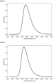
- Figure 1 represents the emission spectrum of Example 1 (10 wt.% in PMMA).
- the emission maximum is at 483 nm.
- the photoluminescence quantum yield (PLQY) is 82%, the half-width is 0.43 eV and the emission decay time is 10 ⁇ s.
- Example 2 was prepared according to AAVO (74 % yield) using 3-bromocarbazole ( CAS 1592-95-6 ) and was used as E0,
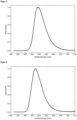
- Figure 2 represents the emission spectrum of Example 2 (10 wt.% in PMMA).
- the emission maximum is at 467 nm.
- the photoluminescence quantum yield (PLQY) is 75%, the half-width is 0.43 eV and the emission decay time is 19 ⁇ s.
- Example 3 was prepared according to
- AAV1 (83 % yield), where 2-chloro-4,6-diphenyl-1,3,5-triazine ( CAS 3842-55-5 ) as E0-2 and 2-fluoro-5-cyanophenylboronic acid pinacol ester as E0-1 and AA V3 (65% yield) was synthesized.
- Figure 3 represents the emission spectrum of example 3 (10 wt.% in PMMA). The emission maximum is at 490 nm. The photoluminescence quantum yield (PLQY) is 74% and the half-width is 0.44 eV.
- PLQY photoluminescence quantum yield
- Figure 4 represents the emission spectrum of Example 4 (10 wt.% in PMMA).
- the emission maximum is at 473 nm.
- the photoluminescence quantum yield (PLQY) is 62%, the half-width is 0.45 eV and the emission decay time is 43 ⁇ s.
- Example 5 was prepared according to
- Figure 5 represents the emission spectrum of Example 5 (10 wt.% in PMMA).
- the emission maximum is at 473 nm.
- the photoluminescence quantum yield (PLQY) is 77%, the half-width is 0.44 eV and the emission decay time is 60 ⁇ s.
- Example 6 was prepared according to
- AAV1 (83 % yield), where 2-chloro-4,6-diphenyl-1,3,5-triazine ( CAS 3842-55-5 ) as E0-2 and 2-fluoro-5-cyanophenylboronic acid pinacol ester as E0-1 and analogous to AAV3 (81 % yield), using 3-bromocarbazole ( CAS 1592-95-6 ) was used as DH.
- the product from the reaction according to AA V3 is then reacted with bis(pinacolato)diboron as follows: and then with according to implemented.
- Figure 6 represents the emission spectrum of Example 6 (10 wt.% in PMMA).
- the emission maximum is at 473 nm.
- the photoluminescence quantum yield (PLQY) is 64%, the half-width is 0.43 eV and the emission decay time is 15 ⁇ s.
- Figure 7 represents the emission spectrum of Example 7 (10 wt.% in PMMA).
- the emission maximum is at 481 nm.
- the photoluminescence quantum yield (PLQY) is 69%, the half-width is 0.43 eV and the emission decay time is 12 ⁇ s.
- Example 8 (10 wt.% in PMMA) is at 466 nm.
- Example 9 (10 wt.% in PMMA) is at 480 nm.
- Example 1 was tested in the OLED components D1 with the following structure (the proportion of the molecule according to the invention in the emission layer is given in mass percent): layer thickness D1 10 100 nm Al 9 2 nm Liq 8 20 nm NBPhen 7 10 nm MAT1 6 50 nm mCBP (70%) : MAT1 (20%) : 1 (10%) 5 10 nm mCBP 4 10 nm TCTA 3 40 nm NPB 2 5 nm HAT-CN 1 50 nm ITO substrate Glass
Landscapes
- Chemical & Material Sciences (AREA)
- Organic Chemistry (AREA)
- Engineering & Computer Science (AREA)
- Materials Engineering (AREA)
- Physics & Mathematics (AREA)
- Spectroscopy & Molecular Physics (AREA)
- Electroluminescent Light Sources (AREA)
- Plural Heterocyclic Compounds (AREA)
Description
- Die Erfindung betrifft organische Moleküle und ihre Verwendung in organischen lichtemittierenden Dioden (OLEDs) und in anderen optoelektronischen Vorrichtungen.
- Die
WO 2013/100540 A1 bezieht sich auf eine Verbindung für eine organische optoelektronische Vorrichtung, dargestellt durch die chemische Formel 1:
WO 2013/100540 A1 definiert. L wird durch die folgenden chemischen Formeln 2-4 dargestellt:
WO 2013/100540 A1 definiert. - Die
EP 3 109 247 A1 bezieht sich auf eine kondensierte cyclische Verbindung und eine organische lichtemittierende Vorrichtung, die diese Verbindung enthält. Die cyclische Verbindung wird durch die Formel 1 repräsentiert:
EP 3 109 247 A1 definiert. - Die
WO 2016/013875 A1 offenbart eine organische Elektrolumineszenzvorrichtung, die eine Anode, eine Kathode und eine organische Schicht zwischen der Anode und der Kathode umfasst, wobei die organische Schicht eine oder mehrere lichtemittierende Schichten und eine oder mehrere Lochtransportschichten umfasst; mindestens eine lichtemittierende Schicht eine oder mehrere Dotierstoffverbindungen und zwei oder mehrere Wirtsverbindungen umfasst; eine erste Wirtsverbindung durch die folgende Formel 1 dargestellt ist; eine zweite Wirtsverbindung durch die folgende Formel 2 dargestellt ist; und mindestens eine Lochtransportschicht, welche die durch die folgende Formel 3 dargestellte Verbindung umfasst:

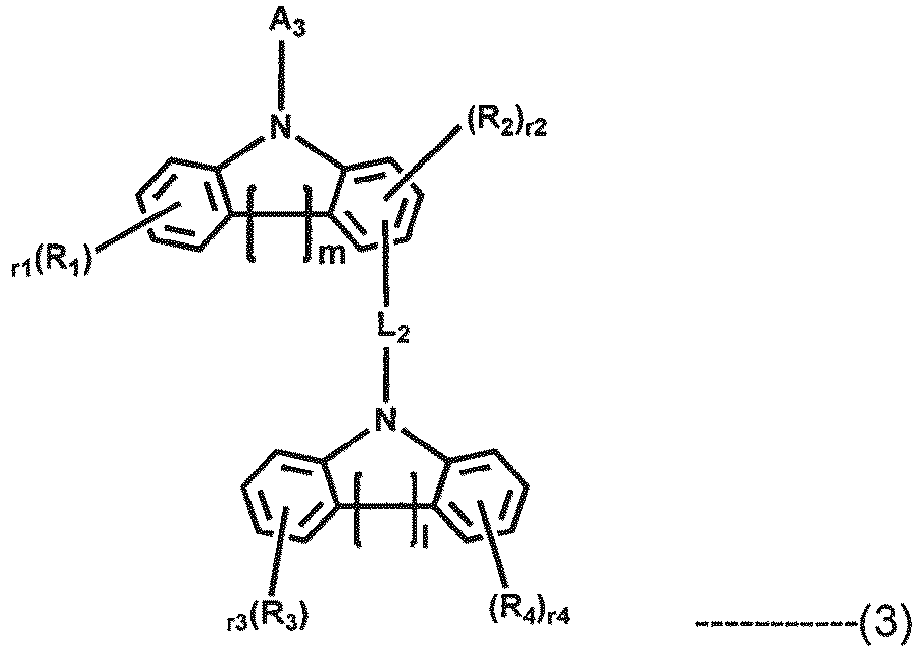
WO 2016/013875 A1 definiert sind. - Die
WO 2015/142036 A1 beschreibt ein Elektronenpuffermaterial, das eine Verbindung umfasst, die ein stickstoffhaltiges Heteroaryl enthält, das aus den durch die folgenden Formeln 1 bis 3 dargestellten Verbindungen ausgewählt ist:
H-(Cz-L1)a-M ------------- (1)
H-(Cz)b-L1-M ------------- (2)


- A stellt dar:

- B stellt dar:

- C stellt dar:

WO 2015/142036 A1 definiert sind. - Die
WO 2013/165192 A1 bezieht sich auf eine organische elektrolumineszente Verbindung, dargestellt durch die folgende Formel 1
WO 2013/165192 A1 definiert sind. - Die Aufgabe der vorliegenden Erfindung besteht darin, Moleküle bereitzustellen, die zur Verwendung in optoelektronischen Vorrichtungen geeignet sind.
- Diese Aufgabe wird durch die Erfindung gelöst, die eine neue Klasse von organischen Molekülen bereitstellt.
- Erfindungsgemäß sind die organischen Moleküle rein organische Moleküle, d. h., sie enthalten im Gegensatz zu Metallkomplexen, die für ihre Verwendung in optoelektronischen Vorrichtungen bekannt sind, keine Metallionen.
- Gemäß der vorliegenden Erfindung weisen die organischen Moleküle Emissionsmaxima im blauen, himmelblauen oder grünen Spektralbereich auf. Die organischen Moleküle weisen insbesondere Emissionsmaxima zwischen 420 nm und 520 nm auf, vorzugsweise zwischen 440 nm und 495 nm, weiter bevorzugt zwischen 450 nm und 470 nm. Die Photolumineszenzquantenausbeuten der erfindungsgemäßen organischen Moleküle betragen insbesondere 70 % und mehr. Die erfindungsgemäßen Moleküle weisen insbesondere eine thermisch aktivierte verzögerte Fluoreszenz (TADF) auf. Die Verwendung der erfindungsgemäßen Moleküle in einer optoelektronischen Vorrichtung, zum Beispiel eine organische lichtemittierende Diode (OLED), führt zu höheren Effizienzen der Vorrichtung. Entsprechende OLEDs weisen eine höhere Stabilität als OLEDs mit bekannten Emittermaterialien und vergleichbarer Farbe auf.
- Das erfindungsgemäße organische Molekül ist ausgewählt aus der Gruppe bestehend aus Formel Ila-1, Formel Ila-2 und Formel Ila-3:

- X ausgewählt ist aus der Gruppe bestehend aus H, SiMe3, SiPh3, CN und CF3;
- ArEWG ausgewählt ist aus der Gruppe bestehend aus den Formeln Ila bis IIc und Ili


- wobei # die Bindungsstelle einer Einfachbindung darstellt, die ArEWG mit dem Phenylring verbindet;
- R1 bei jedem Auftreten unabhängig voneinander ausgewählt ist aus der Gruppe bestehend aus Wasserstoff,
- Deuterium,
- C1-C5-Alkyl,
- wobei ein oder mehrere Wasserstoffatome optional substituiert sind durch Deuterium; C2-C8-Alkenyl,
- wobei ein oder mehrere Wasserstoffatome optional substituiert sind durch Deuterium; C2-C8-Alkinyl,
- wobei ein oder mehrere Wasserstoffatome optional substituiert sind durch Deuterium; und C6-C18-Aryl,
- das optional substituiert ist mit einem oder mehreren Substituenten R6;
- R2 bei jedem Auftreten unabhängig voneinander ausgewählt ist aus der Gruppe bestehend aus Wasserstoff,
- Deuterium,
- C1-C5-Alkyl,
- wobei ein oder mehrere Wasserstoffatome optional substituiert sind durch Deuterium; C2-C8-Alkenyl,
- wobei ein oder mehrere Wasserstoffatome optional substituiert sind durch Deuterium; C2-C8-Alkinyl,
- wobei ein oder mehrere Wasserstoffatome optional substituiert sind durch Deuterium; und C6-C18-Aryl,
- das optional substituiert ist mit einem oder mehreren Substituenten R6;
- Rd bei jedem Auftreten unabhängig voneinander ausgewählt ist aus der Gruppe bestehend aus Wasserstoff, Deuterium, N(R6)2, OR6, Si(R6)3, B(OR6)2, OSO2R6, CF3, CN, F, Br, I,
- C1-C40-Alkyl,
- das optional substituiert ist mit einem oder mehreren Substituenten R6 und
- wobei eine oder mehrere nicht benachbarte CH2-Gruppen optional substituiert sind durch R6C=CR6, C· C, Si(R6)2, Ge(R6)2, Sn(R6)2, C=O, C=S, C=Se, C=NR6, P(=O)(R6), SO, SO2, NR6, O, S oder CONR6;
- C1-C40-Alkoxy,
- das optional substituiert ist mit einem oder mehreren Substituenten R6 und
- wobei eine oder mehrere nicht benachbarte CH2-Gruppen optional substituiert sind durch R6C=CR6, C· C, Si(R6)2, Ge(R6)2, Sn(R6)2, C=O, C=S, C=Se, C=NR6, P(=O)(R6), SO, SO2,
- NR6, O, S oder CONR6;
- C1-C40-Thioalkoxy,
- das optional substituiert ist mit einem oder mehreren Substituenten R6 und
- wobei eine oder mehrere nicht benachbarte CH2-Gruppen optional substituiert sind durch R6C=CR6, C· C, Si(R6)2, Ge(R6)2, Sn(R6)2, C=O, C=S, C=Se, C=NR6, P(=O)(R6), SO, SO2, NR6, O, S oder CONR6;
- C2-C40-Alkenyl,
- das optional substituiert ist mit einem oder mehreren Substituenten R6 und
- wobei eine oder mehrere nicht benachbarte CH2-Gruppen optional substituiert sind durch R6C=CR6, C· C, Si(R6)2, Ge(R6)2, Sn(R6)2, C=O, C=S, C=Se, C=NR6, P(=O)(R6), SO, SO2, NR6, O, S oder CONR6;
- C2-C40-Alkinyl,
- das optional substituiert ist mit einem oder mehreren Substituenten R6 und
- wobei eine oder mehrere nicht benachbarte CH2-Gruppen optional substituiert sind durch R6C=CR6, C· C, Si(R6)2, Ge(R6)2, Sn(R6)2, C=O, C=S, C=Se, C=NR6, P(=O)(R6), SO, SO2, NR6, O, S oder CONR6;
- C6-C60-Aryl,
- das optional substituiert ist mit einem oder mehreren Substituenten R6; und C3-C57-Heteroaryl,
- das optional substituiert ist mit einem oder mehreren Substituenten R6;
- R6 bei jedem Auftreten unabhängig voneinander ausgewählt ist aus der Gruppe bestehend aus Wasserstoff, Deuterium, OPh, CF3, CN, F,
- C1-C5-Alkyl,
wobei optional ein oder mehrere Wasserstoffatome unabhängig voneinander substituiert sind durch Deuterium, CN, CF3 oder F; - C1-C5-Alkoxy,
wobei optional ein oder mehrere Wasserstoffatome unabhängig voneinander substituiert sind durch Deuterium, CN, CF3 oder F; - C1-C5-Thioalkoxy,
wobei optional ein oder mehrere Wasserstoffatome unabhängig voneinander substituiert sind durch Deuterium, CN, CF3 oder F; - C2-C5-Alkenyl,
wobei optional ein oder mehrere Wasserstoffatome unabhängig voneinander substituiert sind durch Deuterium, CN, CF3 oder F; - C2-C5-Alkinyl,
wobei optional ein oder mehrere Wasserstoffatome unabhängig voneinander substituiert sind durch Deuterium, CN, CF3 oder F; - C6-C18-Aryl,
das optional substituiert ist mit einem oder mehrere C1-C5-Alkyl-Substituenten; - C3-C17-Heteroaryl,
das optional substituiert ist mit einem oder mehrere C1-C5-Alkyl-Substituenten; - N(C6-C18-Aryl)2;
- N(C3-C17-Heteroaryl)2,
- und N(C3-C17-Heteroaryl)(C6-C18-aryl);
- RA bei jedem Auftreten, unabhängig voneinander ausgewählt ist aus einer chemischen Struktur der Formel IIA

- oder einer chemischen Struktur der Formel IIB

- wobei RN ausgewählt ist aus der Gruppe bestehend aus Me, iPr, tBu, CN, CF3 und Ph;
- wobei $ die Bindungsstelle einer Einfachbindung darstellt, mittels derer RA angebunden ist.
- wobei RB ausgewählt ist aus der Gruppe bestehend aus
- H,
- Ph,
- CN,
- CF3,
- aus einer chemischen Struktur der Formel IIA-2

- oder einer chemischen Struktur der Formel IIB-2

- wobei RN# ausgewählt ist aus der Gruppe bestehend aus Me, iPr, tBu, CN, CF3 und Ph;
- wobei S die Bindungsstelle einer Einfachbindung darstellt und.
- wobei Rb bei jedem Auftreten unabhängig voneinander ausgewählt ist aus der Gruppe bestehend aus:
- H,
- Me,
- iPr,
- tBu,
- CN,
- CF3,
- Ph, das optional substituiert ist mit einem oder mehreren Substituenten unabhängig ausgewählt aus der Gruppe bestehend aus Me, iPr, tBu, CN, CF3 und Ph,
- Pyridinyl, das optional substituiert ist mit einem oder mehreren Substituenten unabhängig ausgewählt aus der Gruppe bestehend aus Me, iPr, tBu, CN, CF3 und Ph,
- Pyrimidinyl, das optional substituiert ist mit einem oder mehreren Substituenten unabhängig ausgewählt aus der Gruppe bestehend aus Me, iPr, tBu, CN, CF3 und Ph,
- Carbazolyl, das optional substituiert ist mit einem oder mehreren Substituenten unabhängig ausgewählt aus der Gruppe bestehend aus Me, iPr, tBu, CN, CF3 und Ph,
- Triazinyl, das optional substituiert ist mit einem oder mehreren Substituenten unabhängig ausgewählt aus der Gruppe bestehend aus Me, iPr, tBu, CN, CF3 und Ph,
- und N(Ph)2.
- In einer Ausführungsform der Erfindung ist R1 bei jedem Auftreten unabhängig voneinander C6-C18-Aryl, das optional substituiert ist mit einem oder mehreren Substituenten R6.
- In einer Ausführungsform der Erfindung ist R1 bei jedem Auftreten unabhängig voneinander ausgewählt aus der Gruppe bestehend aus
Phenyl (Ph), das optional substituiert ist mit einem oder mehreren Substituenten R6. - In einer Ausführungsform der Erfindung ist R1 gleich Phenyl.
- In einer Ausführungsform der Erfindung ist RN gleich Phenyl.
- In einer Ausführungsform der Erfindung ist RN# gleich Phenyl.
- In einer Ausführungsform der Erfindung ist R2 bei jedem Auftreten unabhängig voneinander ausgewählt aus der Gruppe bestehend aus
- Wasserstoff,
- CN,
- CF3 und
- C6-C18-Aryl, das optional substituiert ist mit einem oder mehreren Substituenten R6.
- In einer Ausführungsform der Erfindung ist R2 bei jedem Auftreten unabhängig voneinander ausgewählt aus der Gruppe bestehend aus
- Wasserstoff,
- CN,
- CF3 und
- Phenyl, das optional substituiert ist mit einem oder mehreren Substituenten R6.
- In einer Ausführungsform der Erfindung ist R2 bei jedem Auftreten unabhängig voneinander ausgewählt aus der Gruppe bestehend aus
Wasserstoff, CN, CF3 und Phenyl. - In einer Ausführungsform der Erfindung ist R2 bei jedem Auftreten unabhängig voneinander ausgewählt aus der Gruppe bestehend aus
Wasserstoff, CN und CF3. - In einer Ausführungsform der Erfindung ist R2 bei jedem Auftreten unabhängig voneinander ausgewählt aus der Gruppe bestehend aus
Wasserstoff und CN. - In einer Ausführungsform der Erfindung ist R2 bei jedem Auftreten gleich Wasserstoff.
- In einer Ausführungsform der organischen Moleküle ist R1 bei jedem Auftreten unabhängig voneinander
- Phenyl, das optional substituiert ist mit einem oder mehreren Substituenten R6, und
- R2, das bei jedem Auftreten unabhängig voneinander ausgewählt ist aus der Gruppe bestehend aus
- Wasserstoff, CN, CF3 und Phenyl, das optional substituiert ist mit einem oder mehreren Substituenten R6.
- In einer Ausführungsform der organischen Moleküle ist R1 bei jedem Auftreten Phenyl,
- R2 ist bei jedem Auftreten unabhängig voneinander ausgewählt aus der Gruppe bestehend aus Wasserstoff, CN, CF3 und Phenyl;
- RN ist bei jedem Auftreten gleich Phenyl, und
- RN# ist bei jedem Auftreten ist gleich Phenyl.
- In einer Ausführungsform der organischen Moleküle ist R1 bei jedem Auftreten Phenyl,
- R2 ist bei jedem Auftreten gleich Wasserstoff,
- RN ist bei jedem Auftreten gleich Phenyl; und
- RN# ist bei jedem Auftreten ist gleich Phenyl.
- In einer Ausführungsform ist R6 ausgewählt aus der Gruppe bestehend aus Me, iPr, tBu, CN, CF3 und Ph.
- In einer Ausführungsform ist X ausgewählt aus der Gruppe bestehend aus SiMe3, SiPh3, CN und CF3.
- In einer bevorzugten Ausführungsform ist X ausgewählt aus der Gruppe bestehend aus CN und CF3.
- In einer bevorzugten Ausführungsform ist X gleich CN.
- In einer Ausführungsform ist RB ausgewählt aus der Gruppe bestehend aus
- H,
- Ph,
- CN,
- CF3,
- oder einer chemischen Struktur der Formel IIB-2

- wobei RN# ausgewählt ist aus der Gruppe bestehend aus Me, iPr, tBu, CN, CF3 und Ph.
- In einer Ausführungsform ist RB ausgewählt aus der Gruppe bestehend aus
- H,
- Ph,
- CN,
- CF3,
- oder einer chemischen Struktur der Formel IIB-2

- wobei RN# gleich Ph ist.
- In einer Ausführungsform ist RB ausgewählt aus der Gruppe bestehend aus
- H,
- Ph,
- CN,
- oder einer chemischen Struktur der Formel IIB-2

- wobei RN# gleich Ph ist.
- In einer Ausführungsform ist RB ausgewählt aus der Gruppe bestehend aus
- H,
- oder einer chemischen Struktur der Formel IIB-2

- wobei RN# gleich Ph ist.
- In einer Ausführungsform ist RB gleich H.
- In einer Ausführungsform ist RB bestehend aus einer chemischen Struktur der Formel IIB-2

- In einer weiteren bevorzugten Ausführungsform ist RB ausgewählt aus der Gruppe bestehend aus
- H,
- oder einer chemischen Struktur der Formel IIB-2

- wobei RN# gleich Ph ist.
- Die erfindungsgemäßen organischen Moleküle umfassen oder bestehen aus einer Struktur, die ausgewählt ist aus der Gruppe bestehend aus Formel Ila-1, Formel Ila-2, und Formel Ila-3:
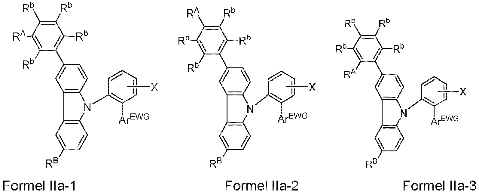
- H,
- Me,
- iPr,
- tBu,
- CN,
- CF3,
- Ph, das optional substituiert ist mit einem oder mehreren Substituenten unabhängig ausgewählt aus der Gruppe bestehend aus Me, iPr, tBu, CN, CF3 und Ph,
- Pyridinyl, das optional substituiert ist mit einem oder mehreren Substituenten unabhängig ausgewählt aus der Gruppe bestehend aus Me, iPr, tBu, CN, CF3 und Ph,
- Pyrimidinyl, das optional substituiert ist mit einem oder mehreren Substituenten unabhängig ausgewählt aus der Gruppe bestehend aus Me, iPr, tBu, CN, CF3 und Ph,
- Carbazolyl, das optional substituiert ist mit einem oder mehreren Substituenten unabhängig ausgewählt aus der Gruppe bestehend aus Me, iPr, tBu, CN, CF3 und Ph,
- Triazinyl, das optional substituiert ist mit einem oder mehreren Substituenten unabhängig ausgewählt aus der Gruppe bestehend aus Me, iPr, tBu, CN, CF3 und Ph,
- und N(Ph)2.
- In einer weiteren Ausführungsform der Erfindung ist Rb bei jedem Auftreten unabhängig voneinander ausgewählt ist aus der Gruppe bestehend aus
- H,
- Me,
- iPr,
- tBu,
- CN,
- CF3,
- Ph, das optional substituiert ist mit einem oder mehreren Substituenten unabhängig ausgewählt aus der Gruppe bestehend aus Me, iPr, tBu, CN, CF3 und Ph,
- Pyridinyl, das optional substituiert ist mit einem oder mehreren Substituenten unabhängig ausgewählt aus der Gruppe bestehend aus Me, iPr, tBu, CN, CF3 und Ph,
- Pyrimidinyl, das optional substituiert ist mit einem oder mehreren Substituenten unabhängig ausgewählt aus der Gruppe bestehend aus Me, iPr, tBu, CN, CF3 und Ph und
- Triazinyl, optional substituiert ist mit einem oder mehreren Substituenten unabhängig ausgewählt aus der Gruppe bestehend aus Me, iPr, tBu, CN, CF3 und Ph.
- In einer weiteren Ausführungsform der Erfindung ist Rb bei jedem Auftreten unabhängig voneinander ausgewählt ist aus der Gruppe bestehend aus
- H,
- CN,
- CF3.
- In einer weiteren Ausführungsform der Erfindung ist Rb bei jedem Auftreten unabhängig voneinander ausgewählt ist aus der Gruppe bestehend aus
H und CN. - In einer zusätzlichen Ausführungsform der Erfindung umfassen oder bestehen die erfindungsgemäßen organischen Moleküle aus einer Struktur, die ausgewählt ist aus der Gruppe bestehend aus Formel Ilc-1, Formel Ilc-2, Formel Ilc-3, Formel Ilc-4 und Formel Ilc-5:


- In einer zusätzlichen Ausführungsform der Erfindung umfassen oder bestehen die erfindungsgemäßen organischen Moleküle aus einer Struktur, die ausgewählt ist aus der Gruppe bestehend aus Formel Ilc-1, Formel Ilc-2, und Formel Ilc-3:

- In einer weiteren Ausführungsform der Erfindung umfassen oder bestehen die erfindungsgemäßen organischen Moleküle aus einer Struktur, die ausgewählt ist aus der Gruppe bestehend aus Formel Ilc-1, Formel Ilc-2, Formel Ilc-3, Formel Ilc-4 und Formel Ilc-5, wobei
Rb bei jedem Auftreten ausgewählt aus der Gruppe bestehend aus H und CN. - In einer weiteren Ausführungsform der Erfindung umfassen oder bestehen die erfindungsgemäßen organischen Moleküle aus einer Struktur, die ausgewählt ist aus der Gruppe bestehend aus Formel Ilc-1, Formel Ilc-2 und Formel Ilc-3, wobei
Rb bei jedem Auftreten ausgewählt aus der Gruppe bestehend aus H und CN. - In einer weiteren Ausführungsform der Erfindung umfassen oder bestehen die erfindungsgemäßen organischen Moleküle aus einer Struktur, die ausgewählt ist aus der Gruppe bestehend aus Formel Ilc-1, Formel Ilc-2, Formel Ilc-3, Formel Ilc-4 und Formel llc-5, wobei
Rb gleich H ist. - In einer weiteren Ausführungsform der Erfindung umfassen oder bestehen die erfindungsgemäßen organischen Moleküle aus einer Struktur, die ausgewählt ist aus der Gruppe bestehend aus Formel Ilc-1, Formel Ilc-2 und Formel Ilc-3, wobei
Rb gleich H ist. - In einer weiteren Ausführungsform der Erfindung umfassen oder bestehen die erfindungsgemäßen organischen Moleküle aus einer Struktur, die ausgewählt ist aus der Gruppe bestehend aus Formel Ilc-1, Formel Ilc-2, Formel Ilc-3, Formel Ilc-4 und Formel llc-5, wobei
Rb gleich CN ist. - In einer weiteren Ausführungsform der Erfindung umfassen oder bestehen die erfindungsgemäßen organischen Moleküle aus einer Struktur, die ausgewählt ist aus der Gruppe bestehend aus Formel Ilc-1, Formel Ilc-2 und Formel Ilc-3, wobei
Rb gleich CN ist. - In einer bevorzugten Ausführungsform der Erfindung umfassen oder bestehen die erfindungsgemäßen organischen Moleküle aus einer Struktur gemäß Formel Ilc-1:

- In einer bevorzugten Ausführungsform der Erfindung umfassen oder bestehen die erfindungsgemäßen organischen Moleküle aus der nachfolgend dargestellten Gruppe:


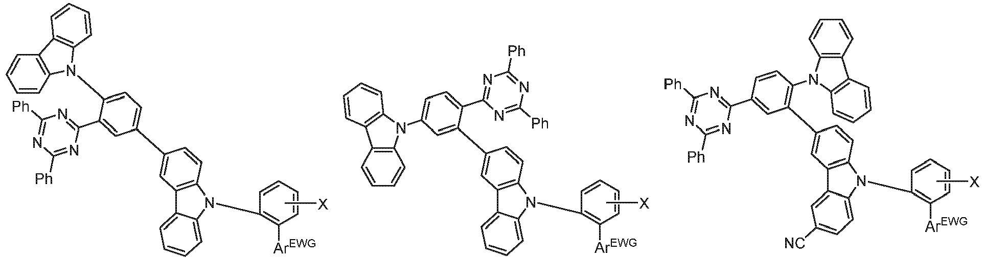


- Gemäß der Erfindung ist ArEWG ausgewählt ist aus der Gruppe bestehend aus


- In einer bevorzugten Ausführungsform der Erfindung ist ArEWG ausgewählt ist aus der Gruppe bestehend aus

- Wie in der gesamten Beschreibung verwendet können die Begriffe "Aryl" und "aromatisch" im weitesten Sinne als jede beliebige mono-, bi- oder polycyclische aromatische Komponente verstanden werden. Dementsprechend enthält eine Arylgruppe 6 bis 60 aromatische Ringatome und eine Heteroarylgruppe enthält 5 bis 60 aromatische Ringatome, von denen mindestens eines ein Heteroatom ist. Nichtsdestotrotz kann die Anzahl von aromatischen Ringatomen in der gesamten Beschreibung in der Definition bestimmter Substituenten als tiefgestellte Anzahl gegeben werden. Insbesondere beinhaltet der heteroaromatische Ring ein bis drei Heteroatome. Die Begriffe "Heteroaryl" und "heteroaromatisch" können im weitesten Sinne als jede beliebige mono-, bi- oder polycyclische heteroaromatische Komponente, die mindestens ein Heteroatom beinhaltet, verstanden werden. Die Heteroatome können bei jedem Auftreten gleich oder unterschiedlich sein und können individuell ausgewählt sein aus der Gruppe bestehend aus N, O und S. Dementsprechend bezieht sich der Begriff "Arylen" auf einen zweiwertigen Substituenten, der zwei Bindungsstellen an andere molekulare Strukturen trägt und somit als eine Verbindungsgliedstruktur dient. Falls eine Gruppe in den beispielhaften Ausführungsformen anders als die hier gegebenen Definitionen definiert ist, zum Beispiel, wenn die Anzahl der aromatischen Ringatome oder die Anzahl von Heteroatomen von der gegebenen Definition abweicht, ist die Definition in den beispielhaften Ausführungsformen anzuwenden. Erfindungsgemäß besteht ein kondensierter (annulierter) aromatischer oder heteroaromatischer Polycyclus aus zwei oder mehreren einzelnen aromatischen oder heteroaromatischen Cyclen, die den Polycyclus durch eine Kondensationsreaktion gebildet haben.
- Insbesondere, wie in der gesamten Beschreibung verwendet, umfasst der Begriff Arylgruppe oder Heteroarylgruppe Gruppen, die über eine beliebige Position der aromatischen oder heteroaromatischen Gruppe gebunden werden können, abgeleitet von Benzol, Naphthalin, Anthracen, Phenanthren, Pyren, Dihydropyren, Chrysen, Perylen, Fluoranthen, Benzanthracen, Benzphenanthren, Tetracen, Pentacen, Benzpyren, Furan, Benzofuran, Isobenzofuran, Dibenzofuran, Thiophen, Benzothiophen, Isobenzothiophen, Dibenzothiophen; Pyrrol, Indol, Isoindol, Carbazol, Pyridin, Chinolin, Isochinolin, Acridin, Phenanthridin, Benzo-5,6-chinolin, Benzo-6,7-chinolin, Benzo-7,8-chinolin, Phenothiazin, Phenoxazin, Pyrazol, Indazol, Imidazol, Benzimidazol, Naphthoimidazol, Phenanthroimidazol, Pyridoimidazol, Pyrazinoimidazol, Chinoxalinoimidazol, Oxazol, Benzoxazol, Napthooxazol, Anthroxazol, Phenanthroxazol, Isoxazol, 1,2-Thiazol, 1,3-Thiazol, Benzothiazol, Pyridazin, Benzopyridazin, Pyrimidin, Benzopyrimidin, 1,3,5-Triazin, Chinoxalin, Pyrazin, Phenazin, Naphthyridin, Carbolin, Benzocarbolin, Phenanthrolin, 1,2,3-Triazol, 1,2,4-Triazol, Benzotriazol, 1,2,3-Oxadiazol, 1,2,4-Oxadiazol, 1,2,5-Oxadiazol, 1,2,3,4-Tetrazin, Purin, Pteridin, Indolizin und Benzothiadiazol oder Kombinationen aus den vorstehend erwähnten Gruppen.
- Wie in der gesamten vorliegenden Beschreibung verwendet, kann der Begriff cyclische Gruppe im weitesten Sinne als mono-, bi- oder polycyclische Komponenten verstanden werden.
- Wie in der gesamten vorliegenden Beschreibung verwendet, kann der Begriff Alkylgruppe im weitesten Sinne als ein beliebiger linearer, verzweigter oder cyclischer Alkylsubstituent verstanden werden. Insbesondere umfasst der Begriff Alkyl die Substituenten Methyl (Me), Ethyl (Et), n-Propyl ("Pr), i-Propyl (iPr), Cyclopropyl, n-Butyl ("Bu), i-Butyl ('Bu), s-Butyl (sBu), t-Butyl (tBu), Cyclobutyl, 2-Methylbutyl, n-Pentyl, s-Pentyl, t-Pentyl, 2-Pentyl, Neopentyl, Cyclopentyl, n-Hexyl, s-Hexyl, t-Hexyl, 2-Hexyl, 3-Hexyl, Neohexyl, Cyclohexyl, 1-Methylcyclopentyl, 2-Methylpentyl, n-Heptyl, 2-Heptyl, 3-Heptyl, 4-Heptyl, Cycloheptyl, 1-Methylcyclohexyl, n-Octyl, 2-Ethylhexyl, Cyclooctyl, 1-Bicyclo[2,2,2]octyl, 2-Bicyclo[2,2,2]-octyl, 2-(2,6-Dimethyl)octyl, 3-(3,7-Dimethyl)octyl, Adamantyl, 2,2,2-Trifluorethyl, 1,1-Dimethyl-n-hex-1-yl, 1,1-Dimethyl-n-hept-1-yl, 1,1-Dimethyl-n-oct-1-yl, 1,1-Dimethyl-n-dec-1-yl, 1,1-Dimethyl-n-dodec-1-yl, 1,1-Dimethyl-n-tetradec-1-yl, 1,1-Dimethyl-n-hexadec-1-yl, 1,1-Dimethyl-n-octadec-1-yl, 1,1-Diethyl-n-hex-1-yl, 1,1-Diethyl-n-hept-1-yl, 1,1-Diethyl-n-oct-1-yl, 1,1-Diethyl-n-dec-1-yl, 1,1-Diethyl-n-dodec-1-yl, 1,1-Diethyl-n-tetradec-1-yl, 1,1-Diethyln-n-hexadec-1-yl, 1,1-Diethyl-n-octadec-1-yl, 1-(n-Propyl)-cyclohex-1-yl, 1-(n-Butyl)-cyclohex-1-yl, 1-(n-Hexyl)-cyclohex-1-yl, 1-(n-Octyl)-cyclohex-1-yl und 1-(n-Decyl)-cyclohex-1-yl.
- Wie in der gesamten vorliegenden Beschreibung verwendet, umfasst der Begriff Alkenyl lineare, verzweigte und cyclische Alkenylsubstituenten. Der Begriff Alkenlygruppe umfasst beispielhaft die Substituenten Ethenyl, Propenyl, Butenyl, Pentenyl, Cyclopentenyl, Hexenyl, Cyclohexenyl, Heptenyl, Cycloheptenyl, Octenyl, Cyclooctenyl oder Cyclooctadienyl.
- Wie in der gesamten Beschreibung verwendet, umfasst der Begriff Alkinyl lineare, verzweigte und cyclische Alkinylsubstituenten. Der Begriff Alkinylgruppe umfasst beispielhaft Ethinyl, Propinyl, Butinyl, Pentinyl, Hexinyl, Heptinyl oder Octinyl.
- Wie in der gesamten Beschreibung verwendet, umfasst der Begriff Alkoxy lineare, verzweigte und cyclische Alkoxysubstituenten. Der Begriff Alkoxygruppe umfasst beispielhaft Methoxy, Ethoxy, n-Propoxy, i-Propoxy, n-Butoxy, i-Butoxy, s-Butoxy, t-Butoxy und 2-Methylbutoxy.
- Wie in der gesamten Beschreibung verwendet, umfasst der Begriff Thioalkoxy lineare, verzweigte und cyclische Thioalkoxysubstituenten, in denen das O der beispielhaften Alkoxygruppen durch S ersetzt wird.
- Wie in der gesamten Beschreibung verwendet, können die Begriffe "Halogen" und "Halo" im weitesten Sinne derart verstanden werden, dass sie vorzugsweise Fluor, Chlor, Brom oder lod sind.
- Wenn Wasserstoff hierin erwähnt wird, kann er bei jedem Auftreten auch durch Deuterium ersetzt werden.
- Es versteht sich, dass, wenn ein molekulares Fragment derart beschrieben ist, dass es ein Substituent ist oder anderweitig an eine andere Komponente befestigt ist, kann dessen Name so geschrieben werden, als wenn es ein Fragment (z. B. Naphtyl, Dibenzofuryl) wäre oder als wenn es das gesamte Molekül (z. B. Naphthalin, Dibenzofuran) wäre. Wie hierin verwendet, werden diese unterschiedlichen Möglichkeiten, einen Substituenten oder ein befestigtes Fragment zu bezeichnen, als äquivalent betrachtet.
- In einer Ausführungsform weisen die erfindungsgemäßen organischen Moleküle eine Lebensdauer im angeregten Zustand von nicht mehr als 150 µs, von nicht mehr als 100 µs, insbesondere von nicht mehr als 50 µs, weiter bevorzugt von nicht mehr als 10 µs oder nicht mehr als 7 µs in einem Film aus Poly(methylmethacrylat) (PMMA) mit 10 Gew.-% des organischen Moleküls bei Raumtemperatur auf.
- In einer Ausführungsform der Erfindung stellen die erfindungsgemäßen organischen Moleküle thermisch aktivierte verzögerte Fluoreszenz(TADF)-Emitter dar, die einen • EST-Wert, der der Energiedifferenz zwischen dem ersten angeregten Singulettzustand (S1) und dem ersten angeregten Triplettzustand (T1) entspricht, von weniger als 5000 cm-1, vorzugsweise weniger als 3000 cm-1, weiter bevorzugt weniger als 1500 cm-1, noch weiter bevorzugt weniger als 1000 cm-1 oder sogar weniger als 500 cm-1 aufweisen.
- In einer weiteren Ausführungsform der Erfindung weisen die erfindungsgemäßen organischen Moleküle eine Emissionsspitze im sichtbaren oder nahen Ultraviolettbereich, d. h. im Bereich einer Wellenlänge von 380 bis 800 nm, mit einer Halbwertsbreite von weniger als 0,50 eV, vorzugsweise weniger als 0,48 eV, weiter bevorzugt weniger als 0,45 eV, noch weiter bevorzugt weniger als 0,43 eV oder sogar weniger als 0,40 eV in einem Film aus Poly(methylmethacrylat) (PMMA) mit 10 Gew.-% des organischen Moleküls bei Raumtemperatur auf.
- In einer weiteren Ausführungsform der Erfindung weisen die erfindungsgemäßen organischen Moleküle einen "blauen Materialindex" ("blue material index") (BMI), der durch Dividieren der Photolumineszenquantenausbeute (PLQY) in % durch die ClEy-Farbkoordinate des emittierten Lichts berechnet wird, von mehr als 150, insbesondere mehr als 200, vorzugsweise mehr als 250, weiter bevorzugt mehr als 300 oder sogar mehr als 500 auf.
- Orbitalenergien und angeregte Zustandsenergien können entweder mithilfe experimenteller Verfahren oder durch Berechnungen, die quantenchemische Verfahren nutzen, insbesondere Berechnungen auf Grundlage der Dichtefunktionaltheorie, bestimmt werden. Die Energie des höchsten besetzen Molekülorbitals EHOMO wird durch Verfahren, die dem Fachmann bekannt sind, anhand cyclischer Voltametriemessungen mit einer Genauigkeit von 0,1 eV bestimmt. Die Energie des niedrigsten unbesetzten Molekülorbitals ELUMO wird als EHOMO + Egap berechnet, wobei Egap folgendermaßen bestimmt wird: Für Hostverbindungen wird der Versatz des Emissionsspektrums eines Films mit 10 Gew.-% des Hosts in Poly(methylmethacrylat) (PMMA) als Egapverwendet, sofern nicht anderweitig angegeben. Für Emittermoleküle wird Egapals die Energie bestimmt, bei der die Anregungs- und Emissionsspektren eines Films mit 10 Gew.-% des Emitters in PMMA durchqueren.
- Die Energie des ersten angeregten Triplettzustands T1 wird anhand des Versatzes des Emissionsspektrums bei geringer Temperatur, typischerweise bei 77 K, bestimmt. Bei Hostverbindungen, bei denen der erste angeregte Singulettzustand und der geringste Triplettzustand energetisch durch >0,4 eV getrennt sind, ist die Phosphoreszenz üblicherweise in einem stationären Spektrum in 2-Me-THF sichtbar. Die Triplettenergie kann somit als der Versatz des Phosphoreszenzspektrums bestimmt werden. Für TADF-Emittermoleküle wird die Energie des ersten angeregten Triplettzustands T1 anhand des Versatzes des verzögerten Emissionsspektrums bei 77 K bestimmt, sofern nicht anderweitig in einem Film aus PMMA mit 10 Gew.-% des Emitters gemessen. Sowohl für die Host- und Emitterverbindungen wird die Energie des ersten angeregten Singulettzustands S1 anhand des Versatzes des Emissionsspektrums bestimmt, sofern nicht anderweitig in einem Film aus PMMA mit 10 Gew.-% der Host- oder Emitterverbindung gemessen. Der Versatz eines Emissionsspektrums wird durch Berechnen des Schnittpunkts der Tangente zum Emissionsspektrum mit der x-Achse bestimmt. Die Tangente zum Emissionsspektrum wird an der Seite des Emissionsbereichs mit hoher Energie, d. h., wo der Emissionsbereich ansteigt, indem er sich von Werten mit hoher Energie zu Werten mit niedriger Energie bewegt, und am Punkt bei halbem Maximum der maximalen Intensität des Emissionsspektrums festgelegt.
- Ein weiterer Aspekt der Erfindung betrifft einen Prozess zum Herstellen erfindungsgemäßer organischer Moleküle (mit optionaler anschließender Reaktion), wobei eine Palladium-katalysierte Kreuzkupplungreaktion verwendet wird:


- Ra ist bei jedem Auftreten unabhängig voneinander ausgewählt aus der Gruppe bestehend aus
- RA
- Wasserstoff, Deuterium, N(R6)2, OR6, Si(R6)3, B(OR6)2, OSO2R6, CF3, CN, F, Br, I, C1-C40-Alkyl,
- das optional substituiert ist mit einem oder mehreren Substituenten R6 und
- wobei eine oder mehrere nicht benachbarte CH2-Gruppen optional substituiert sind durch R6C=CR6, C· C, Si(R6)2, Ge(R6)2, Sn(R6)2, C=O, C=S, C=Se, C=NR6, P(=O)(R6), SO, SO2, NR6, O, S oder CONR6;
- C1-C40-Alkoxy,
- das optional substituiert ist mit einem oder mehreren Substituenten R6 und
- wobei eine oder mehrere nicht benachbarte CH2-Gruppen optional substituiert sind durch R6C=CR6, C•C, Si(R6)2, Ge(R6)2, Sn(R6)2, C=O, C=S, C=Se, C=NR6, P(=O)(R6), SO, SO2, NR6, O, S oder CONR6;
- C1-C40-Thioalkoxy,
- das optional substituiert ist mit einem oder mehreren Substituenten R6 und
- wobei eine oder mehrere nicht benachbarte CH2-Gruppen optional substituiert sind durch R6C=CR6, C· C, Si(R6)2, Ge(R6)2, Sn(R6)2, C=O, C=S, C=Se, C=NR6, P(=O)(R6), SO, SO2, NR6, O, S oder CONR6;
- C2-C40-Alkenyl,
- das optional substituiert ist mit einem oder mehreren Substituenten R6 und
- wobei eine oder mehrere nicht benachbarte CH2-Gruppen optional substituiert sind durch R6C=CR6, C· C, Si(R6)2, Ge(R6)2, Sn(R6)2, C=O, C=S, C=Se, C=NR6, P(=O)(R6), SO, SO2, NR6, O, S oder CONR6;
- C2-C40-Alkinyl,
- das optional substituiert ist mit einem oder mehreren Substituenten R6 und
- wobei eine oder mehrere nicht benachbarte CH2-Gruppen optional substituiert sind durch R6C=CR6, C. C, Si(R6)2, Ge(R6)2, Sn(R6)2, C=O, C=S, C=Se, C=NR6, P(=O)(R6), SO, SO2, NR6, O, S oder CONR6;
- C6-C60-Aryl,
das optional substituiert ist mit einem oder mehreren Substituenten R6; und - C3-C57-Heteroaryl,
- das optional substituiert ist mit einem oder mehreren Substituenten R6.
- Erfindungsgemäß reagiert E2, eine ArEWG-Gruppe, die mit der Kupplungsgruppe CG1 substituiert ist, mit E3, einem Phenyl, welches mit X, der Kupplungsgruppe CG2 und einmal F substituiert ist. Die Kupplungsgruppen CG1 und CG2 sind so als Reaktionspaar gewählt, dass die ArEWG-Gruppe von E2 an der Substitutionsposition CG2 von E3 eingeführt wird. Bevorzugt wird hierbei eine sogenannte Suzuki-Kupplung. Hierbei wird entweder CG1 aus Cl, Br oder I gewählt und CG2 aus einer Boronsäure oder einem Boronsäureester, insbesondere einem Boronsäurepinakolester, gewählt, oder analog CG2 aus Cl, Br oder I gewählt und CG1 aus einer Boronsäure oder einem Boronsäureester, insbesondere einem Boronsäurepinakolester, gewählt.
- D-H ist gemäß folgender Synthesewege herstellbar


- Typischerweise wird Pd2(dba)3 (Tris(dibenzylidenaceton)dipalladium(0)) als Palladium-Katalysator verwendet, aber Alternativen sind dem Fachmann bekannt. Beispielhaft wird der Ligand ausgewählt aus S-Phos ([2-Dicyclohexylphosphino-2',6'-dimethoxy-1,T'-biphenyl]; oder SPhos), XPhos (2-(dicyclohexylphosphino)-2",4",6"-triisopropylbiphenyl oder XPhos) und P(Cy)s (Tricyclohexylphosphin). Das Salz ist beispielhaft ausgewählt aus Kaliumphosphat, Kaliumcarbonat und Kaliumacetat und das Lösungsmittel kann entweder ein reines Lösungsmittel wie Toluol oder Dioxan oder ein Gemisch wie beispielsweise Toluol/Dioxan/Wasser sein. Dem Fachmann ist bekannt, welche Pd-Katalysator-, Ligand-, Salz- und Lösungsmittelkombination am wahrscheinlichsten zu hohen Ausbeuten führt.
- Für die Reaktion eines Stickstoff-Heterocyclus in einer nukleophilen aromatischen Substitution mit einem Arylhalogenid, vorzugsweise einem Arylfluorid, beinhalten typische Bedingungen die Verwendung einer Base, wie etwa tribasisches Kaliumphosphat oder Natriumhydrid, zum Beispiel in einem aprotischen polaren Lösungsmittel, wie etwa beispielsweise Dimethylsulfoxid (DMSO) oder N,N-Dimethylformamid (DMF).
- Ein alternativer Syntheseweg umfasst die Einführung eines Stickstoff-Heterocyclus über Kupfer- oder Palladium-katalysierte Kopplung an ein Arylhalogenid oder Arylpseudohalogenid, vorzugsweise ein Arylbromid, ein Aryliodid, Aryltriflat oder ein Aryltosylat.
- Ein weiterer Aspekt der Erfindung betrifft die Verwendung eines erfindungsgemäßen organischen Moleküls als Lumineszenzemitter oder als Absorber und/oder als Hostmaterial und/oder als Elektronentransportmaterial und/oder als Lochinjektionsmaterial und/oder als Lochblockiermaterial in einer optoelektronischen Vorrichtung.
- Die organische elektrolumineszierende Vorrichtung kann im weitesten Sinne als eine beliebige Vorrichtung auf Grundlage organischer Materialien verstanden werden, die zum Emittieren von Licht im sichtbaren oder nahen ultravioletten (UV) Bereich, d. h. im Bereich einer Wellenlänge von 380 bis 800 nm, geeignet ist. Weiter bevorzugt kann die organische elektrolumineszierende Vorrichtung in der Lage sein, Licht im sichtbaren Bereich, d. h. von 400 bis 800 nm, zu emittieren.
- Im Zusammenhang mit solch einer Verwendung ist die organische optoelektronische Vorrichtung insbesondere ausgewählt aus der Gruppe bestehend aus:
- organischen lichtemittierenden Dioden (OLEDs),
- lichtemittierenden elektrochemischen Zellen,
- OLED-Sensoren, insbesondere in Gas- und Dampfsensoren nach außen nicht hermetisch abgeschirmt,
- organischen Dioden,
- organischen Solarzellen,
- organischen Transistoren,
- organischen Feldeffekttransistoren,
- organischen Lasern und
- Abwärtswandlungselementen (Down-Konversionselement, englisch: Down Conversion Element).
- In einer bevorzugten Ausführungsform im Zusammenhang mit solch einer Verwendung ist die organische elektrolumineszierende Vorrichtung eine Vorrichtung ausgewählt aus der Gruppe bestehend aus einer organischen lichtemittierenden Diode (OLED), einer lichtemittierenden elektrochemischen Zelle (LEC) und eines lichtemittierenden Transistors.
- Im Falle der Verwendung beträgt der Anteil des erfindungsgemäßen organischen Moleküls in der Emissionsschicht in einer optoelektronischen Vorrichtung, insbesondere in OLEDs, 1 Gew.-% bis 99 Gew.-%, insbesondere 5 Gew.-% bis 80 Gew.-%. In einer alternativen Ausführungsform beträgt die Menge des organischen Moleküls in der Emissionsschicht 100 Gew.-%.
- In einer Ausführungsform umfasst die lichtemittierende Schicht nicht nur die erfindungsgemäßen organischen Moleküle, sondern auch ein Hostmaterial, dessen Triplett(T1)- und Singulett(S1)-Energieniveaus energetisch höher sind als die Triplett(T1)- und Singulett(S1)-Energieniveaus des organischen Moleküls.
- Ein weiterer Aspekt der Erfindung betrifft eine Zusammensetzung, umfassend oder bestehend aus:
- (a) mindestens einem erfindungsgemäßen organischen Molekül, insbesondere in der Form eines Emitters und/oder eines Hosts, und
- (b) einem oder mehreren Emitter- und/oder Hostmaterialien, die sich von dem organischen Molekül gemäß der Erfindung unterscheiden, und
- (c) optional einem oder mehreren Farbstoffen und/oder einem oder mehreren Lösungsmitteln.
- In einer Ausführungsform umfasst die lichtemittierende Schicht eine Zusammensetzung (oder besteht (im Wesentlichen) daraus), umfassend oder bestehend aus:
- (a) mindestens einem erfindungsgemäßen organischen Molekül, insbesondere in der Form eines Emitters und/oder eines Hosts, und
- (b) einem oder mehreren Emitter- und/oder Hostmaterialien, die sich von dem organischen Molekül gemäß der Erfindung unterscheiden, und
- (c) optional einem oder mehreren Farbstoffen und/oder einem oder mehreren Lösungsmitteln.
- Besonders bevorzugt umfasst die lichtemittierende Schicht EML eine Zusammensetzung (oder besteht (im Wesentlichen) daraus), umfassend oder bestehend aus:
- (i) 1-50 Gew.-%, vorzugsweise 5-40 Gew.-%, insbesondere 10-30 Gew.-% eines oder mehrerer erfindungsgemäßer organischer Moleküle;
- (ii) 5-99 Gew.-%, vorzugsweise 30-94,9 Gew.-%, insbesondere 40-89 Gew.-% der mindestens einen Hostverbindung H; und
- (iii) optional 0-94 Gew.-%, vorzugsweise 0,1-65 Gew.-%, insbesondere 1-50 Gew.-% der mindestens einen weiteren Hostverbindung D mit einer Struktur, die von der Struktur der erfindungsgemäßen Moleküle abweicht; und
- (iv) optional 0-94 Gew.-%, vorzugsweise 0-65 Gew.-%, insbesondere 0-50 Gew.-% eines Lösungsmittels; und
- (v) optional 0-30 Gew.-%, insbesondere 0-20 Gew.-%, vorzugsweise 0-5 Gew.-% von mindestens einem weiteren Emittermolekül F mit einer Struktur, die von der Struktur der erfindungsgemäßen Moleküle abweicht.
- Vorzugsweise kann Energie von der Hostverbindung H zu einem oder mehreren organischen Molekülen gemäß der Erfindung übertragen werden, insbesondere vom ersten angeregten Triplettzustand T1(H) der Hostverbindung H zum ersten angeregten Triplettzustand T1(E) des einen oder der mehreren erfindungsgemäßen organischen Moleküle und/oder vom ersten angeregten Singulettzustand S1(H) der Hostverbindung H zum ersten angeregten Singulettzustand S1(E) des einen oder der mehreren erfindungsgemäßen organischen Moleküle übertragen.
- In einer weiteren Ausführungsform umfasst die lichtemittierende Schicht EML eine Zusammensetzung (oder besteht (im Wesentlichen) daraus), umfassend oder bestehend aus:
- (i) 1-50 Gew.-%, vorzugsweise 5-40 Gew.-%, insbesondere 10-30 Gew.-% eines erfindungsgemäßen organischen Moleküls;
- (ii) 5-99 Gew.-%, vorzugsweise 30-94,9 Gew.-%, insbesondere 40-89 Gew.-% einer Hostverbindung H; und
- (iii) optional 0-94 Gew.-%, vorzugsweise 0,1-65 Gew.-%, insbesondere 1-50 Gew.-% der mindestens einen weiteren Hostverbindung D mit einer Struktur, die von der Struktur der erfindungsgemäßen Moleküle abweicht; und
- (iv) optional 0-94 Gew.-%, vorzugsweise 0-65 Gew.-%, insbesondere 0-50 Gew.-% eines Lösungsmittels; und
- (v) optional 0-30 Gew.-%, insbesondere 0-20 Gew.-%, vorzugsweise 0-5 Gew.-% von mindestens einem weiteren Emittermolekül F mit einer Struktur, die von der Struktur der erfindungsgemäßen Moleküle abweicht.
- In einer Ausführungsform weist die Hostverbindung H ein höchstes besetztes Molekülorbital HOMO(H) mit einer Energie EHOMO(H) im Bereich von -5 bis -6,5 eV auf, und die mindestens eine weitere Hostverbindung D weist ein höchstes besetztes Molekülorbital HOMO(D) mit einer Energie EHOMO(D) auf, wobei EHOMO(H) > EHOMO(D).
- In einer weiteren Ausführungsform weist die Hostverbindung H ein niedrigstes unbesetztes Molekülorbital LUMO(H) mit einer Energie ELUMO(H) auf, und die mindestens eine weitere Hostverbindung D weist ein niedrigstes unbesetztes Molekülorbital LUMO(D) mit einer Energie ELUMO(D) auf, wobei ELUMO(H) > ELUMO(D).
- In einer Ausführungsform weist die Hostverbindung H ein höchstes besetztes Molekülorbital HOMO(H) mit einer Energie EHOMO(H) und ein niedrigstes unbesetztes Molekülorbital LUMO(H) mit einer Energie ELUMO(H) auf, und
- die mindestens eine weitere Hostverbindung D weist ein höchstes besetztes Molekülorbital HOMO(D) mit einer Energie EHOMO(D) und ein niedrgistes unbesetztes Molekülorbital LUMO(D) mit einer Energie ELUMO(D) auf,
- das organische Molekül gemäß der Erfindung weist ein höchstes besetztes Molekülorbital HOMO(E) mit einer Energie EHOMO(E) und ein niedrgistes unbesetztes Molekülorbital LUMO(E) mit einer Energie ELUMO(E) auf,
- EHOMO(H) > EHOMO(D) und die Differenz zwischen dem Energieniveau des höchsten besetzten Molekülorbitals HOMO(E) des organischen Moleküls gemäß der Erfindung (EHOMO(E)) und dem Energieniveau des höchsten besetzten Molekülorbitals HOMO(H) der Hostverbindung H (EHOMO(H)) zwischen -0,5 eV und 0,5 eV, weiter bevorzugt zwischen -0,3 eV und 0,3 eV, noch weiter bevorzugt zwischen -0,2 eV und 0,2 eV oder sogar zwischen -0,1 eV und 0,1 eV beträgt; und
- ELUMO(H) > ELUMO(D) und die Differenz zwischen dem Energieniveau des niedrigsten unbesetzten Molekülorbitals LUMO(E) des organischen Moleküls gemäß der Erfindung (ELUMO(E)) und dem niedrigsten unbesetzten Molekülorbital LUMO(D) der mindestens einen weiteren Hostverbindung D (ELUMO(D)) zwischen -0,5 eV und 0,5 eV, weiter bevorzugt zwischen -0,3 eV und 0,3 eV, noch weiter bevorzugt zwischen -0,2 eV und 0,2 eV oder sogar zwischen -0,1 eV und 0,1 eV beträgt.
- In einem weiteren Aspekt betrifft die Erfindung eine organische optoelektronische Vorrichtung, die ein organisches Molekül oder eine Zusammensetzung des hier beschriebenen Typs umfasst, insbesondere in der Form einer Vorrichtung ausgewählt aus der Gruppe bestehend aus organischer lichtemittierender Diode (OLED), lichtemittierender elektrochemischer Zelle, OLED-Sensor, insbesondere Gas- und Dampfsensoren, die nach außen nicht hermetisch abgeschirmt sind, organischer Diode, organischer Solarzelle, organischem Transistor, organischem Feldeffekttransistor, organischem Laser und Down-Konversionselement (Abwärtswandlungselement).
- In einer bevorzugten Ausführungsform ist die organische elektrolumineszierende Vorrichtung eine Vorrichtung ausgewählt aus der Gruppe bestehend aus einer organischen lichtemittierenden Diode (OLED), einer lichtemittierenden elektrochemischen Zelle (LEC) und eines lichtemittierenden Transistors.
- In einer Ausführungsform der optoelektronischen Vorrichtung gemäß der Erfindung wird das organische Molekül gemäß der Erfindung als Emissionsmaterial in einer lichtemittierenden Schicht EML verwendet.
- In einer Ausführungsform der optoelektronischen Vorrichtung gemäß der Erfindung besteht die lichtemittierende Schicht EML aus der hier beschriebenen Zusammensetzung gemäß der Erfindung.
- Wenn die organische elektrolumineszierende Vorrichtung eine OLED ist, kann sie exemplarisch die folgende Schichtstruktur aufweisen:
- 1. Substrat
- 2. Anodenschicht A
- 3. Lochinjektionsschicht, HIL
- 4. Lochtransportschicht, HTL
- 5. Elektronenblockierschicht, EBL
- 6. emittierende Schicht, EML
- 7. Lochblockierschicht, HBL
- 8. Elektronentransportschicht, ETL
- 9. Elektroneninjektionsschicht, EIL
- 10. Kathodenschicht,
- Außerdem kann die organische elektrolumineszierende Vorrichtung optional eine oder mehrere schützende Schichten umfassen, die die Vorrichtung vor schädigender Exposition gegenüber schädlichen Faktoren in der Umgebung schützt, einschließlich zum Beispiel Feuchtigkeit, Dampf und/oder Gasen.
- In einer Ausführungsform der Erfindung ist die organische elektrolumineszierende Vorrichtung eine OLED, die die folgende umgekehrte Schichtstruktur aufweist:
- 1. Substrat
- 2. Kathodenschicht
- 3. Elektroneninjektionsschicht, EIL
- 4. Elektronentransportschicht, ETL
- 5. Lochblockierschicht, HBL
- 6. emittierende Schicht, B
- 7. Elektronenblockierschicht, EBL
- 8. Lochtransportschicht, HTL
- 9. Lochinjektionsschicht, HIL
- 10. Anodenschicht A
- In einer Ausführungsform der Erfindung ist die organische elektrolumineszierende Vorrichtung eine OLED, die eine gestapelte Architektur aufweisen kann. In dieser Architektur sind die einzelnen Einheiten, im Gegensatz zur typischen Anordnung, wo die OLEDs Seite an Seite positioniert sind, aufeinander gestapelt. Gemischtes Licht kann mit OLEDs, die eine gestapelte Architektur aufweisen, generiert werden, insbesondere kann weißes Licht durch gestapelte blaue, grüne und rote OLEDs generiert werden. Außerdem kann die OLED, die eine gestapelte Architektur aufweist, optional eine Ladungserzeugungsschicht (CGL) umfassen, die typischerweise zwischen zwei OLED-Untereinheiten positioniert ist und typischerweise aus einer n-dotierten und p-dotierten Schicht besteht, wobei die n-dotierte Schicht einer CGL typischerweise näher an der Anodenschicht positioniert ist.
- In einer Ausführungsform der Erfindung ist die organische elektrolumineszierende Vorrichtung eine OLED, die zwei oder mehrere Emissionsschichten zwischen Anode und Kathode umfasst. Insbesondere umfasst diese sogenannte Tandem-OLED drei Emissionsschichten, wobei eine Emissionsschicht rotes Licht emittiert, eine Emissionsschicht grünes Licht emittiert und eine Emissionsschicht blaues Licht emittiert, und kann optional weitere Schichten umfassen, wie etwa Ladeungserzeugungsschichten, Blockier- oder Transportschichten zwischen den einzelnen Emissionsschichten. In einer weiteren Ausführungsform sind die Emissionsschichten benachbart gestapelt. In einer weiteren Ausführungsform umfasst die Tandem-OLED eine Ladungserzeugungsschichtung zwischen jeweils zwei Emissionsschichten. Zusätzlich können benachbarte Emissionsschichten oder Emissionsschichten, die durch eine Ladungserzeugungsschicht getrennt sind, zusammengeführt werden.
- Das Substrat kann durch ein beliebiges Material oder eine beliebige Zusammensetzung von Materialien gebildet werden. Am häufigsten werden Glasobjektträger als Substrate verwendet. Alternativ können dünne Metallschichten (z. B. Kupfer, Gold, Silber oder Aluminiumfolien) oder Kunststofffolien oder -objektträger verwendet werden. Dies kann ein höheres Maß an Flexibilität ermöglichen. Die Anodenschicht A besteht meistens aus Materialien, die es ermöglichen, einen (im Wesentlichen) transparenten Film zu erhalten. Da mindestens eine von beiden Elektroden (im Wesentlichen) transparent sein sollte, um eine Lichtemission von der OLED zu ermöglichen, ist entweder die Anodenschicht A oder die Kathodenschicht C transparent. Vorzugsweise umfasst die Anodenschicht A einen großen Gehalt an oder besteht sogar aus transparenten leitenden Oxiden (TCOs). Solch eine Anodenschicht A kann beispielhaft Indiumzinnoxid, Aluminumzinkoxid, fluordotiertes Zinnoxid, Indiumzinkoxid, PbO, SnO, Zirkoniumoxide, Molybdänoxid, Vanadiumoxid, Wolframoxid, Graphit, dotiertes Si, dotiertes Ge, dotiertes GaAs, dotiertes Polyanilin, dotiertes Polypyrrol und/oder dotiertes Polythiophen umfassen.
- Besonders bevorzugt besteht die Anodenschicht A (im Wesentlichen) aus Indiumzinnoxid (ITO) (z. B. (InO3)0,9(SnO2)0,1). Die Rauheit der Anodenschicht A, die von den transparenten leitenden Oxiden (TCOs) verursacht wird, kann durch Verwenden einer Lochinjektionsschicht (HIL) ausgeglichen werden. Außerdem kann die HIL die Injektion von Quasiladungsträgern (z. B. Löchern) erleichtern, in die der Transport von Quasiladungsträgern vom TCO zur Lochtransportschicht (HTL) erleichtert wird. Die Lochinjektionsschicht (HIL) kann Poly-3,4-ethylendioxythiophen (PEDOT), Polystyrolsulfonat (PSS), MoOz, VzOs, CuPC oder Cul, insbesondere ein Gemisch aus PEDOT und PSS umfassen. Die Lochinjektionsschicht (HIL) kann außerdem die Diffusion von Metall aus der Anodenschicht A in die Lochtransportschicht (HTL) verhindern. Die HIL kann beispielhaft PEDOT:PSS (Poly-3,4-ethylendioxythiophen: Polystyrolsulfonat), PEDOT (Poly-3,4-ethylendioxythiophen), mMTDATA (4,4;4'-Tris[phenyl(m-tolyl)amino]triphenylamin), Spiro-TAD (2,2;7,7'Tetrakis(n,n-diphenylamino)-9,9'-spirobifluoren), DNTPD (N1,N1'-(Biphenyl-4,4'-diyl)bis(N1-phenyl-N4,N4-di-m-tolylbenzol-1,4-diamin), NPB (N,N'-Nis-(1-naphthalenyl)-N,N'-bis-phenyl-(1,1'-biphenyl)-4,4'-diamin), NPNPB (N,N'-Diphenyl-N,N'-di-[4-(N,N-diphenyl-amino)phenyl]benzidin), MeO-TPD (N,N,N•,N•-Tetrakis(4-methoxyphenyl)benzidin), HAT-CN (1,4,5,8,9,11-Hexaazatriphenylen-hexacarbonitril) und/oder Spiro-NPD (N,N'Diphenyl-N,N'bis-(1-naphthyl)-9,9'spirobifluoren-2,7-diamin) umfassen.
- Benachbart zur Anodenschicht A oder zur Lochinjektionsschicht (HIL) befindet sich typischerweise eine Lochtransportschicht (HTL). Hierin kann jede beliebige Lochtransportverbindung verwendet werden. Beispielhaft können elektronenreiche heteroaromatische Verbindungen, wie etwa Triarylamine und/oder Carbazole, als Lochtransportverbindung verwendet werden. Die HTL kann die Energiebarriere zwischen der Anodenschicht A und der lichtemittierenden Schicht EML reduzieren. Die Lochtransportschicht (HTL) kann außerdem eine Elektronenblockierschicht (EBL) sein. Vorzugsweise trägt die Lochtransportverbindung hohe Energieniveaus ihrer Triplettzustände T1. Beispielhaft kann die Lochtransportschicht (HTL) einen sternförmigen Heterocyclus umfassen, wie etwa Tris(4-carbazoyl-9-ylphenyl)amin (TCTA), Poly-TPD (Poly(4-butylphenyldiphenylamin)), [alpha]-NPD (Poly(4-butylphenyldiphenylamin)), TAPC (4,4'Cyclohexyliden-bis[N,N-bis(4-methylphenyl)benzenamin]), 2-TNATA (4,4;4'Tris[2-naphthyl(phenyl)amino]triphenylamin), Spiro-TAD, DNTPD, NPB, NPNPB, MeO-TPD, HAT-CN und/oder TrisPcz (9,9'-Diphenyl-6-(9-phenyl-9H-carbazol-3-yl)-9H,9'H-3,3'-bicarbazol). Zusätzlich kann die HTL eine p-dotierte Schicht umfassen, die aus einem anorganischen oder organischen Dotierstoff in einer organischen Lochtransportmatrix besteht. Übergangsmetalloxide, wie etwa Vanadiumoxid, Molybdänoxid oder Wolframoxid können beispielhaft als anorganischer Dotierstoff verwendet werden. Tetrafluortetracyanochinodimethan (F4-TCNQ), Kupferpentafluorbenzoat (Cu(I)pFBz) oder Übergangsmetallkomplexe können beispielhaft als organischer Dotierstoff verwendet werden.
- Die EBL kann beispielhaft mCP (1,3-Bis(carbazol-9-yl)benzol), TCTA, 2-TNATA, mCBP (3,3-Di(9H-carbazol-9-yl)biphenyl), Tris-Pcz, CzSi (9-(4-Tert-butylphenyl)-3,6-bis(triphenylsilyl)-9H-carbazol) und/oder DCB (N,N-Dicarbazolyl-1,4-dimethylbenzol) umfassen.
- Benachbart zur Lochtransportschicht (HTL) befindet sich typischerweise die lichtemittierende Schicht EML. Die lichtemittierende Schicht EML umfasst mindestens ein lichtemittierendes Molekül. Insbesondere umfasst die EML mindestens ein lichtemittierendes Molekül gemäß der Erfindung. In einer Ausführungsform umfasst die lichtemittierende Schicht nur die erfindungsgemäßen organischen Moleküle. Typischerweise umfasst die EML zusätzlich ein oder mehrere Hostmaterialien. Beispielhaft ist das Hostmaterial ausgewählt aus CBP (4,4'-Bis-(N-carbazolyl)-biphenyl), mCP, mCBP Sif87 (Dibenzo[b,d]thiophen-2-yltriphenylsilan), CzSi, Sif88 (Dibenzo[b,d]thiophen-2-yl)diphenylsilan), DPEPO (Bis[2-(diphenylphosphino)phenyl]etheroxid), 9-[3-(Dibenzofuran-2-yl)phenyl]-9H-carbazol, 9-[3-(Dibenzofuran-2-yl)phenyl]-9H-carbazol, 9-[3-(Dibenzothiophen-2-yl)phenyl]-9H-carbazol, 9-[3,5-Bis(2-dibenzofuranyl)phenyl]-9H-carbazol, 9-[3,5-Bis(2-dibenzothiophenyl)phenyl]-9H-carbazol, T2T (2,4,6-Tris(biphenyl-3-yl)-1,3,5-triazin), T3T (2,4,6-Tris(triphenyl-3-yl)-1,3,5-triazin) und/oder TST (2,4,6-Tris(9,9-spirobifluoren-2-yl)-1,3,5-triazin). Das Hostmaterial sollte typischerweise so ausgewählt sein, dass es erste Triplett(T1)- und erste Singulett(S1)-Energieniveaus aufweist, die energetisch höher sind als die ersten Triplett(T1)- und ersten Singulett(S1)-Energieniveaus des organischen Moleküls.
- In einer Ausführungsform der Erfindung umfasst die EML ein sogenanntes gemischtes Hostsystem mit mindestens einem lochdominanten Host und einem elektronendominanten Host. In einer besonderen Ausführungsform umfasst die EML genau ein erfindungsgemäßes lichtemittierendes Molekül und ein gemischtes Hostsystem, umfassend T2T als Elektronen-dominanter Host und einen Host ausgewählt aus CBP, mCP, mCBP, 9-[3-(Dibenzofuran-2-yl)phenyl]-9H-carbazol, 9-[3-(Dibenzofuran-2-yl)phenyl]-9H-carbazol, 9-[3-(Dibenzothiophen-2-yl)phenyl]-9H-carbazol, 9-[3,5-Bis(2-dibenzofuranyl)phenyl]-9H-carbazol und 9-[3,5-Bis(2-dibenzothiophenyl)phenyl]-9H-carbazol als Loch-dominanter Host. In einer weiteren Ausführungsform umfasst die EML 50-80 Gew.-%, vorzugsweise 60-75 Gew.-% eines Hosts ausgewählt aus CBP, mCP, mCBP, 9-[3-(Dibenzofuran-2-yl)phenyl]-9H-carbazol, 9-[3-(Dibenzofuran-2-yl)phenyl]-9H-carbazol, 9-[3-(Dibenzothiophen-2-yl)phenyl]-9H-carbazol, 9-[3,5-Bis(2-dibenzofuranyl)phenyl]-9H-carbazol und 9-[3,5-Bis(2-dibenzothiophenyl)phenyl]-9H-carbazol; 10-45 Gew.-%, vorzugsweise 15-30 Gew.-% von T2T und 5-40 Gew.-%, vorzugsweise 10-30 Gew.-% des erfindungsgemäßen lichtemittierenden Moleküls.
- Benachbart zur lichtemittierenden Schicht EML kann sich eine Elektronentransportschicht (ETL) befinden. Hierin kann jeder beliebige Elektronenüberträger verwendet werden. Beispielhaft können Verbindungen mit wenigen Elektronen, wie etwa beispielsweise Benzimidazole, Pyridine, Triazole, Oxadiazole (z. B. 1,3,4-Oxadiazol), Phosphinoxide und Sulfon verwendet werden. Ein Elektronentransporter kann außerdem ein sternenförmiger Heterocyclus sein, wie etwa 1,3,5-Tri(1-phenyl-1H-benzo[d]imidazol-2-yl)phenyl (TPBi). Die ETL kann NBphen (2,9-Bis(naphthalen-2-yl)-4,7-diphenyl-1,10-phenanthrolin), Alq3 (Aluminium-tris(8-hydroxychinolin)), TSPO1 (Diphenyl-4-triphenylsilylphenyl-phosphinoxid), BPyTP2 (2,7 -Di(2,2--bipyridin-5-yl)triphenyl), Sif87 (Dibenzo[b,d]thiophen-2-yltriphenylsilan), Sif88 (Dibenzo[b,d]thiophen-2-yl)diphenylsilan), BmPyPhB (1,3-Bis[3,5-di(pyridin-3-yl)phenyl]benzol) und/oder BTB (4,4'Bis-[2-(4,6-diphenyl-1,3,5-triazinyl)]-1,1-biphenyl) umfassen. Optional kann die ETL mit Materialien, wie etwa Liq, dotiert sein. Die Elektronentransportschicht (ETL) kann außerdem Löcher blockieren oder eine Lochblockierschicht (HBL) wird eingeführt.
- Die HBL kann beispielhaft BCP (2,9-Dimethyl-4,7-diphenyl-1,10-phenanthrolin = Bathocuproin), BAlq (Bis(8-hydroxy-2-methylchinolin)-(4-phenylphenoxy)aluminium), NBphen (2,9-Bis(naphthalen-2-yl)-4,7-diphenyl-1,10-phenanthrolin), Alq3 (Aluminium-tris(8-hydroxychinolin)), TSPO1 (Diphenyl-4-triphenylsilylphenyl-phosphinoxid), T2T (2,4,6-Tris(biphenyl-3-yl)-1,3,5-triazin), T3T (2,4,6-Tris(triphenyl-3-yl)-1,3,5-triazin), TST (2,4,6-Tris(9,9'spirobifluoren-2-yl)-1 ,3,5-triazin) und/oder TCB/TCP (1,3,5-Tris(N-carbazolyl)benzol/ 1,3,5-Tris(carbazol)-9-yl) benzol) umfassen.
- Benachbart zur Elektronentransportschicht (ETL) kann sich eine Kathodenschicht C befinden. Beispielhaft kann die Kathodenschicht C ein Metall (z. B. Al, Au, Ag, Pt, Cu, Zn, Ni, Fe, Pb, LiF, Ca, Ba, Mg, In, W oder Pd) oder eine Metalllegierung umfassen oder daraus bestehen. Aus praktischen Gründen kann die Kathodenschicht außerdem aus (im Wesentlichen) intransparenten Metallen, wie etwa Mg, Ca oder Al, bestehen. Alternativ oder zusätzlich kann die Kathodenschicht C außerdem Graphit und/oder Kohlenstoffnanoröhren (CNTs) umfassen. Alternativ kann die Kathodenschicht C außerdem aus nanoskaligen Silberdrähten bestehen.
- Eine OLED kann ferner optional eine Schutzschicht zwischen der Elektronentransportschicht (ETL) und der Kathodenschicht (die als Elektroneninjektionsschicht (EIL) bezeichnet werden kann) umfassen. Diese Schicht kann Lithiumfluorid, Cäsiumfluorid, Silber, Liq (8-Hydroxychinolinolatolithium), LizO, BaF2, MgO und/oder NaF umfassen.
- Optional können auch die Elektronentransportschicht (ETL) und/oder eine Lochblockierschicht (HBL) eine oder mehrere Hostverbindungen umfassen.
- Um das Emissionsspektrum und/oder das Absorptionsspektrum der lichtemittierenden Schicht EML weiter zu modifizieren, kann die lichtemittierende Schicht EML ferner ein oder mehrere weitere Emittermoleküle F umfassen. Solch ein Emittermolekül F kann ein beliebiges fachbekanntes Emittermolekül sein. Vorzugsweise ist solch ein Emittermolekül F ein Molekül mit einer Struktur, die von der Struktur der erfindungsgemäßen Moleküle abweicht. Das Emittermolekül F kann optional ein TADF-Emitter sein. Alternativ kann das Emittermolekül F optional ein fluoreszierendes und/oder phosphoreszierendes Emittermolekül sein, das in der Lage ist, das Emissionsspektrum und/oder das Absorptionsspektrum der lichtemittierenden Schicht EML zu wechseln. Beispielhaft können Triplett- und/oder Singulettexzitonen von dem Emittermolekül gemäß der Erfindung zum Emittermolekül F übertragen werden, bevor es sich zum Ausgangszustand S0 entspannt, indem Licht typischerweise rotverschoben wird, und zwar im Vergleich zu dem Licht, das von dem Emittermolekül E emittiert wird. Optional kann das Emittermolekül F außerdem Zwei-Photonen-Wirkungen hervorrufen (d. h. die Absorption von zwei Photonen mit der halben Energie des Absorptionsmaximums).
- Optional kann eine organische elektrolumineszierende Vorrichtung (z. B. eine OLED) beispielhaft eine im Wesentlichen weiße organische elektrolumineszierende Vorrichtung sein. Beispielhaft kann solch eine weiße organische elektrolumineszierende Vorrichtung mindestens ein (dunkel-) blaues Emittermolekül und ein oder mehrere Emittermoleküle, die grünes und/oder rotes Licht emittieren, umfassen. Dann kann außerdem optional wie vorstehend beschrieben eine Energieübertragung zwischen zwei oder mehreren Molekülen, erfolgen.
- Wie hierin verwendet, wenn im bestimmten Zusammenhang nicht konkreter definiert, ist die Bezeichnung der Farben von emittiertem und/oder absorbiertem Licht wie folgt:
violett: Wellenlängenbereich von >380-420 nm; dunkelblau: Wellenlängenbereich von >420-480 nm; himmelblau: Wellenlängenbereich von >480-500 nm; grün: Wellenlängenbereich von >500-560 nm; gelb: Wellenlängenbereich von >560-580 nm; orange: Wellenlängenbereich von >580-620 nm; rot: Wellenlängenbereich von >620-800 nm. - In Bezug auf Emittermoleküle beziehen sich solche Farben auf das Emissionsmaximum. Aus diesem Grund weist beispielhaft ein dunkelblauer Emitter ein Emissionsmaximum im Bereich von >420 bis 480 nm auf, ein himmelblauer Emitter weist ein Emissionsmaximum im Bereich von >480 bis 500 nm auf, ein grüner Emitter weist ein Emissionsmaximum in einem Bereich von >500 bis 560 nm auf, ein roter Emitter weist ein Emissionsmaximum in einem Bereich von >620 bis 800 nm auf.
- Ein dunkelblauer Emitter kann vorzugsweise ein Emissionsmaximum von unter 480 nm, weiter bevorzugt unter 470 nm, noch weiter bevorzugt unter 465 nm oder sogar unter 460 nm aufweisen. Es beträgt typischerweise mehr als 420 nm, vorzugsweise mehr als 430 nm, weiter bevorzugt mehr als 440 nm oder sogar mehr als 450 nm.
- Dementsprechend betrifft ein weiterer Aspekt der vorliegenden Erfindung eine OLED, die eine externe Quanteneffizienz bei 1000 cd/m2 von mehr als 8 %, weiter bevorzugt von mehr als 10 %, weiter bevorzugt von mehr als 13 %, noch weiter bevorzugt von mehr als 15 % oder sogar mehr als 20 % aufweist und/oder ein Emissionsmaximum zwischen 420 nm und 500 nm, vorzugsweise zwischen 430 nm und 490 nm, weiter bevorzugt zwischen 440 nm und 480 nm, noch weiter bevorzugt zwischen 450 nm und 470 nm aufweist und/oder einen LT80-Wert bei 500 cd/m2 von mehr als 100 h, vorzugsweise mehr als 200 h, weiter bevorzugt mehr als 400 h, noch weiter bevorzugt mehr als 750 h oder sogar mehr als 1000 h aufweist. Dementsprechend betrifft ein weiterer Aspekt der vorliegenden Erfindung eine OLED, deren Emission eine ClEy-Farbkoordinate von weniger als 0,45, vorzugsweise weniger als 0,30, weiter bevorzugt weniger als 0,20 oder noch weiter bevorzugt weniger als 0,15 oder sogar weniger als 0,10 aufweist.
- Ein weiterer Aspekt der vorliegenden Erfindung betrifft eine OLED; die Licht bei einem unterschiedlichen Farbpunkt emittiert. Gemäß der vorliegenden Erfindung emittiert die OLED Licht mit einem schmalen Emissionsbereich (kleine Halbwertsbreite (FWHM)). In einem Aspekt emittiert die OLED gemäß der Erfindung Licht mit einer FWHM der Hauptemissionsspitze von weniger als 0,50 eV, vorzugsweise weniger als 0,48 eV, weiter bevorzugt weniger als 0,45 eV, noch weiter bevorzugt weniger als 0,43 eV oder weniger als 0,40 eV.
- Ein weiterer Aspekt der vorliegenden Erfindung betrifft eine OLED, die Licht mit ClEx- und ClEy-Farbkoordinaten nahe den ClEx- (= 0,131) und ClEy- (= 0,046) -Farbkoordinaten der primären Farbe blau (ClEx = 0,131 und ClEy = 0,046) emittiert, wie durch ITU-R Recommendation BT.2020 (Rec. 2020) definiert, und ist somit zur Verwendung bei Ultra-High-Definition(UHD)-Displays, z. B. UHD-TVs, geeignet. In herkömmlichen Anwendungen werden typischerweise nach oben emittierende (obere Elektrode ist transparent) Vorrichtungen verwendet, wobei Testvorrichtung, wie sie in der gesamten Beschreibung verwendet werden, nach unten emittierende Vorrichtungen darstellen (untere Elektrode und Substrat sind transparent). Die ClEy-Farbkoordinate einer blauen Vorrichtung kann durch bis zu einem Faktor von zwei reduziert werden, wenn der Wechsel von einer nach unten zu einer nach oben emittierenden Vorrichtung erfolgt, während die ClEx nahezu unverändert bleibt (Okinaka et al. (2015), 22.1: Invited Paper: New Fluorescent Blue Host Materials for Achieving Low Voltage in OLEDs, SID Symposium Digest of Technical Papers, 46; doi:10.1002/sdtp.10480). Dementsprechend betrifft ein weiterer Aspekt der vorliegenden Erfindung eine OLED, deren Emission eine CIEx-Farbkoordinate von zwischen 0,02 und 0,30, vorzugsweise zwischen 0,03 und 0,25, weiter bevorzugt zwischen 0,05 und 0,20 oder weiter bevorzugt zwischen 0,08 und 0,18 oder sogar zwischen 0,10 und 0,15 und/oder eine ClEy-Farbkoordinate von zwischen 0,00 und 0,45, vorzugsweise zwischen 0,01 und 0,30, weiter bevorzugt zwischen 0,02 und 0,20 oder noch weiter bevorzugt zwischen 0,03 und 0,15 oder sogar zwischen 0,04 und 0,10 aufweist.
- In einem weiteren Aspekt betrifft die Erfindung ein Verfahren zum Herstellen einer optoelektronischen Komponente. In diesem Fall wird ein organisches Molekül der Erfindung verwendet.
- Die organische elektrolumineszierende Vorrichtung, insbesondere die OLED gemäß der vorliegenden Erfindung, kann mithilfe von Dampfabscheidung und/oder Flüssigkeitsbehandlung hergestellt werden. Dementsprechend wird mindestens eine Schicht
- mithilfe eines Sublimationsprozesses hergestellt,
- mithilfe eines organischen Dampfphasenabscheidungsprozesses hergestellt,
- mithilfe eines Trägergassublimationsprozesses hergestellt,
- mit Lösung verarbeitet oder gedruckt.
- Die Verfahren, die zur Herstellung der organischen elektrolumineszierenden Vorrichtung, insbesondere der OLED gemäß der vorliegenden Erfindung, verwendet werden, sind im Fach bekannt. Die verschiedenen Schichten werden mithilfe eines nachfolgenden Abscheidungsprozesses einzeln und aufeinanderfolgend auf einem geeigneten Substrat abgeschieden. Die einzelnen Schichten können mithilfe der gleichen oder unterschiedlicher Abscheidungsverfahren abgeschieden werden.
- Dampfabscheidungsprozesse umfassen beispielhaft thermische (Co-)Verdampfung, chemische Dampfabscheidung und physikalische Dampfabscheidung. Für eine aktive Matrix-OLED-Anzeige wird eine AMOLED-Rückwand als Substrat verwendet. Die einzelne Schicht kann aus Lösungen oder Dispersionen, die adäquate Lösungsmittel nutzen, verarbeitet werden. Der Lösungsabscheidungsprozess umfasst beispielhaft Rotationsbeschichten, Tauchbeschichten und Spritzdrucken. Flüssigkeitsbehandlung kann optional in einer inerten Atmosphäre (z. B. in einer Stickstoffatmosphäre) durchgeführt werden und das Lösungsmittel kann optional vollständig oder teilweise unter Verwendung von im Stand der Technik bekannten Mitteln entfernt werden.
-
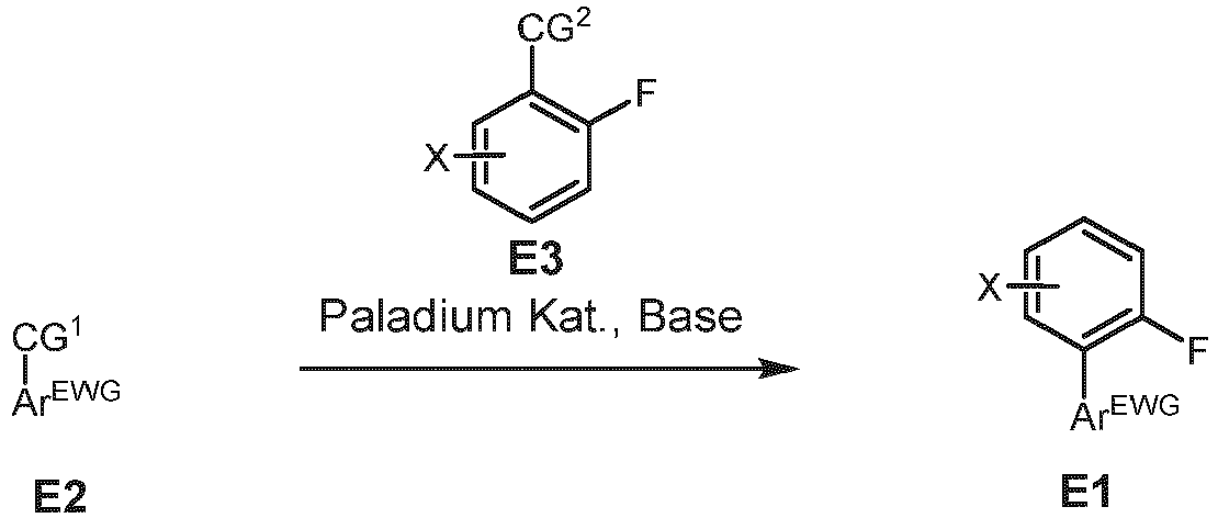

-

- E0 (1,20 Äquivalente), 6-RB-substituiertes 3-Bromcarbazol (1,00 Äquivalente), Pd2(dba)3 (0,03 Äquivalente), 2-Dicyclohexylphosphino-2;4',6triisopropylbiphenyl (XPhos) (0,12 Äquivalente) und tribasisches Kaliumphosphat (1,50 Äquivalente) werden unter Stickstoffatmosphäre in Toluol-/Wassergemisch (Verhältnis von 10:1, 3 ml Toluol pro mmol Arylbromid) bei 110 °C 16 Stunden lang gerührt. Anschließend wird das Reaktionsgemisch filtriert und der Rückstand mit Dichlormethan gewaschen. Das Lösungsmittel wird entfernt. Das erhaltene Rohprodukt wird durch Umkristallisation oder Säulenchromatographie aufgereinigt und als Feststoff erhalten. Anstelle eines Boronsäureesters kann eine entsprechende Boronsäure verwendet werden.
-


-

- X-substituiertes Fluorophenylboronsäurepinakolester E0-1 (1,20 Äquivalente), 2-,4-di-R1-substituierts-6-Chloro-1,3,5-Triazin E0-2 (1,00 Äquivalente), Pd2(dba)3 (0,03 Äquivalente), Tricyclohexylphosphin (PCys) (0,07 Äquivalente) und tribasisches Kaliumphosphat (2,50 Äquivalente) werden unter Stickstoffatmosphäre in Dioxan-/Toluol-/Wassergemisch (Verhältnis von 4:1:1, 4 ml Dioxan pro mmol Triazin) bei 110 °C 16 Stunden lang gerührt. Anschließend wird das Reaktionsgemisch filtriert und der Rückstand mit Dichlormethan gewaschen. Das Lösungsmittel wird entfernt. Das erhaltene Rohprodukt wird durch Umkristallisation oder Säulenchromatographie gereinigt und das Produkt E1-II wird als Feststoff erhalten.
- Anstelle eines Boronsäureesters kann eine entsprechende Boronsäure verwendet werden.
-

- E0-3 (1,00 Äquivalente) und E0-4 (2,00 Äquivalente) werden in Dichlormethan gelöst und in einem Eisbad gekühlt. Antimon(V)-chloride (1,00 Äquivalente) wird tropfenweise zur Lösung hinzugegeben, die Reaktionsmischung für eine Stunde bei Raumtemperatur gerührt und anschließend bei 45 °C für 6 Stunden gerührt. Das Zwischenprodukt wird gefiltert und mit Dichlormethan gewaschen.
- Der getrocknete Feststoff wird zu einer gekühlten 25%-igen Ammoniaklösung (0 - 5 °C) gegeben und über Nacht bei Raumtemperatur gerührt. Die Reaktionsmischung filtriert und der gewonnene Feststoff mit Wasser gewaschen. Der Feststoff wird zu DMF gegeben und bei 155 °C für 30 Minuten gerührt. Der ausgefallene Feststoff wird heiß Filtriert. Wasser wird zur heißen DMF-Lösung gegeben um das Produkt auszufällen. Das Produkt E1-II wird durch Filtration erhalten.
-

- E1-II (1,00 Äquivalente), das entsprechende Donormolekül D-H (1,00 Äquivalente) und tribasisches Kaliumphosphat (4,00 Äquivalente) werden unter Stickstoffatmosphäre in DMSO suspendiert und bei 120 °C (16 h) gerührt. Anschließend wird das Reaktionsgemisch in eine gesättigte Natriumchloridlösung gegeben und drei Mal mit Dichlormethan extrahiert. Die kombinierten organischen Phasen werden zwei Mal mit gesättigter Natriumchloridlösung gewaschen, über MgSO4 getrocknet und das Lösungsmittel wird entfernt. Das Rohprodukt wird durch Umkristallisation oder durch Flash-Chromatographie gereinigt. Das Produkt wird als Feststoff erhalten.
- Alternativ kann in AA V3 beispielsweise halogensubstituiertes Carbazol D-H-Hal, insbesondere ein 3-Brom substituiertes Carbazol, zum Beispiel 3-Bromcarbazol, anstelle von D-H verwendet werden.
- In einer Folgereaktion kann eine Boronsäureester-Gruppe oder eine Boronsäure-Gruppe beispielhaft an der Position der einen oder mehreren Halogensubstituenten, die via D-H-Hal eingeführt wurden, eingeführt werden und so den entsprechenden Carbazol-3-ylboronsäureester oder die entsprechende Carbazol-3-boronsäure ergeben, beispielsweise durch die Reaktion mit Bis(pinacol)diboronsäureester (CAS-Nr. 73183-34-3). Anschließend kann ein Substituent


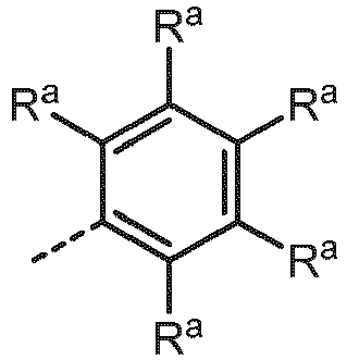

- Alternativ lässt sich die Bromierung eines Carbozolderivates in einer Reaktion mit N-Bromosuccinimid herstellen wie beispielsweise im folgenden Reaktionsschema dargestellt ist:

- HPLC-MS-Spektroskopie wird auf einem HPLC durch Agilent (1100er Serie) mit MS-Detektor (Thermo LTQ XL) durchgeführt.
- Beispielsweise wird eine Umkehrphasensäule 4,6 mm x 150 mm, Partikelgröße 3,5 µm von Agilent (ZORBAX Eclipse Plus 95Ä C18, 4,6 x 150 mm, 3.5 µm HPLC column) im HPLC verwendet. Die HPLC-MS-Messungen werden bei Raumtemperatur (RT) mit folgenden Gradienten durchgeführt:
Durchflussrate
Lösungsmittel A: H2O (90 %) MeCN (10 %) Lösungsmittel B: H2O (10 %) MeCN (90 %) Lösungsmittel C: THF (50 %) MeCN (50 %) - Für die Messungen wird ein Injektionsvolumen von 5 µl aus einer Lösung mit einer Konzentration von 0,5 mg/ml entnommen.
- Die Ionisierung der Probe wird durch APCI (chemische lonisation bei Atmosphärendruck) entweder im positiven (APCI +) oder negativen (APCI -) lonisierungsmodus durchgeführt.
- Cyclische Voltammogramme werden anhand von Lösungen mit einer Konzentration von 10-3 mol/l der organischen Moleküle in Dichlormethan oder eines geeigneten Lösungsmittels und eines geeigneten Trägerelektrolyts (z. B. 0,1 mmol/l von Tetrabutylammoniumhexafluorphosphat) gemessen. Die Messungen werden bei Raumtemperatur unter Stickstoffatmosphäre mit einer Drei-Elektroden-Baugruppe durchgeführt (Arbeits- und Gegenelektroden: Pt-Draht, Referenzelektrode: Pt-Draht) und mithilfe von FeCp2/FeCp2 + als interner Standard kalibriert. Die HOMO-Daten wurden mithilfe von Ferrocen als interner Standard gegenüber einer gesättigten Kalomel-Elektrode (SCE) korrigiert.
- Molekulare Strukturen werden unter Verwendung der BP68-Funktion und des Identitätsauflösungsansatzes (RI) optimiert. Anregungsenergien werden mithilfe der (BP68-) optimierten Strukturen unter Verwendung von zeitabhängigen DFT- (TD-DFT-) Strukturen berechnet. Orbitale und angeregte Zustandsenergien werden mit der B2LYP-Funktion berechnet. Def2-SVP-Ausgangssätze und ein m4-Raster zur numerischen Integration werden verwendet. Das Turbomole-Programmpaket wird für alle Berechnungen verwendet.
-
- Probenvorbehandlung: Rotationsbeschichtung
- Vorrichtung: Spin150, SPS euro.
- Die Probenkonzentration beträgt 1 mg/ml, angesetzt in Chloroform oder Dichlormethan. Zu 1 ml der entsprechenden Lösung werden 9 mg PMMA hinzugefügt. Mit 50 µl der resultierenden Lösung wird der entsprechende Dünnfilm hergestellt.
- Programm: 1) 3 s bei 400 U/min; 2) 20 s bei 1000 U/min bei 1000 Upm/ s. 3) 10 s bei 4000 U/min bei 1000 Upm/s. Die Filme wurden nach dem Beschichten für 1 min bei 70 °C an Luft auf einer Präzisionsheizplatte von LHG getrocknet.
- Photolumineszenz-Spektroskopie und TCSPC (Zeitkorrelierte Einzelphotonenzählung) Stationäre Emissionsspektroskope wird mit einem Fluoreszenzspektrometer der Horiba Scientific, Modell FluoroMax-4 durchgeführt, ausgestattet mit einer 150 W Xenon-Arc Lampe, Anregungs- und Emissionsmonochromatoren und einer Hamamatsu R928 Photomultiplier-Röhre, sowie einer "zeit-korrelierten Einphotonzähl" (Time-correlated single-photon counting, TCSPC)-Option. Hierbei wurde die Probenkammer kontinuierlich mit Stickstoff gespült (Durchflussrate > 800 ml/ min) Emissions- und Anregungsspektren wurden korrigiert durch Standardkorrekturkurven.
- Emissionsabklingzeiten werden unter Verwendung des gleichen Systems mithilfe des TCSPC-Verfahrens mit FM-2013-Ausrüstung und einem Horiba Yvon TCSPC Hub bestimmt.
- Anregungsquellen:
- NanoLED 370 (Wellenlänge: 371 nm, Impulsdauer: 1,1 ns)
- NanoLED 290 (Wellenlänge: 294 nm, Impulsdauer: <1 ns)
- SpectraLED 310 (Wellenlänge: 314 nm)
- SpectraLED 355 (Wellenlänge: 355 nm).
- Die Auswertung (exponentielles Fitten) erfolgte mit dem Softwarepaket DataStation und der DAS 6 Auswertungssoftware. Der Fit wurde über die Chi-Quadrat-Methode angegeben

- Zeitaufgelöste Transienten werden darüber hinaus an einem FS5 Fluoreszenzspektrometer von Edinburgh Instruments vermessen. im Vergleich zu Messungen an dem vergleichbaren HORIBA System, ermöglicht das FS5 eine erhöhte Lichtausbeute und somit ein verbessertes Verhältnis zwischen Probenemission und Hintergrundrauschen, welches besonders Messungen verzögert fluoreszierender Emitter verbessert. Hierbei wird die zu untersuchende Probe über eine breitbandige Xenon-Lampe angeregt (150 W Xenon arc lamp). Das FS5 nutzt Czerny-Turner Monochromatoren sowohl für selektive Anregungs- als auch Emissionswellenlängen. Die Photolumineszenz der Probe wird über einen R928P Photomultiplier-Röhre detektiert, wobei die Photokathode des Detektors die zeitaufgelöste Messung im spektralen Bereich von 200 nm bis 870 nm ermöglicht. Die temperaturstabilisierte Detektoreinheit gewährleistet darüber hinaus eine Dunkelzählrate unter 300 Ereignissen pro Sekunde. Zur Bestimmung der Abklingzeit des PL Transienten wird anschließend der µs- Bereich mit Hilfe von drei Exponentialfunktionen angenähert. Über Amplitudengewichtung ergibt sich eine gemittelte Lebensdauer τDF für die verzögerte Fluoreszenz von

- Die Messung der Photolumineszenzquantenausbeute (PLQY) erfolgte mittels eines Absolute PL Quantum Yield Measurement C9920-03G-Systems der Hamamatsu Photonics. Dieses besteht aus einer 150 W Xenon-Gasentladungslampe, automatisch justierbaren Czerny-Turner Monochromatoren (250 - 950 nm) und einer Ulbricht-Kugel mit hochreflektierender Spektralon-Beschichtung (einem Teflon-Derivat), die über ein Glasfaserkabel mit einem PMA-12 Vielkanaldetektor mit BT- (back thinned-) CCD-Chip mit 1024 x 122 Pixeln (Größe 24 x 24 µm) verbunden ist. Die Auswertung der Quanteneffizienz und der CIE-Koordinaten erfolgte mit Hilfe der Software U6039-05 Version 3.6.0.Emissionsmaxima werden in nm angegeben, Quantenausbeuten Φ in % und CIE-Koordinaten als x-, y-Werte.
- PLQY wird mithilfe des folgenden Protokolls bestimmt:
- 1) Durchführung der Qualitätssicherung: Als Referenzmaterial dient Anthracene in Ethanol mit bekannter Konzentration.
- 2) Ermitteln der Anregungswellenlänge: Es wurde zuerst das Absorbtionsmaximum des organischen Moleküls bestimmt und mit diesem angeregt.
- 3) Durchführung der Probenmessung:
Es wurde von entgasten Lösungen und Filmen unter Stickstoff-Atmosphäre die absolute Quantenausbeute bestimmt. - Die Berechnung erfolgte systemintern nach folgender Gleichung:

- OLED-Vorrichtung, die erfindungsgemäße organische Moleküle umfassen, können unter Verwendung von Vakuumabscheidungsverfahren hergestellt werden. Wenn eine Schicht mehr als eine Verbindung enthält, wird der Gewichtsprozentsatz von einer oder mehreren Verbindungen in % angegeben. Die Gesamtgewichtsprozentsatzwerte betragen 100 %, wenn also ein Wert nicht angegeben ist, gleicht der Anteil dieser Verbindung der Differenz zwischen den angegebenen Werten und 100 %.
- Die nicht vollständig optimierten OLEDs werden mithilfe von Standardverfahren und des Messens von Elektrolumineszenzspektren, der externen Quanteneffizienz (in %) in Abhängigkeit von der Intensität, charakterisiert, unter Verwendung des durch die Photodiode detektierten Lichts und des Stroms berechnet. Die Lebensdauer der OLED-Vorrichtung wird von der Veränderung der Leuchtdichte während des Betriebs bei konstanter Stromdichte extrahiert. Der LT50-Wert entspricht der Zeit, bei der die gemessene Luminanz auf 50 % der anfänglichen Leuchtdichte gesunken ist, analog entspricht LT80 dem Zeitpunkt, bei dem die gemessene Leuchtdichte auf 80 % der anfänglichen Leuchtdichte gesunken ist, LT95 dem Zeitpunkt, bei dem die gemessene Leuchtdichte auf 95 % der anfänglichen Leuchtdichte gesunken ist, usw.
- Beschleunigte Messungen der Lebensdauer werden durchgeführt (z. B. Anwenden von erhöhten Stromdichten). Beispielhaft werden LT80-Werte bei 500 cd/m2 mithilfe der folgenden Gleichung bestimmt:

- Der Wert entspricht dem Durchschnitt von mehreren Pixeln (typischerweise zwei bis acht), wobei die Standardabweichung zwischen diesen Pixeln gegeben ist. Die Figuren zeigen die Datenserien für einen OLED-Pixel.
-

-
- AAVO (74 % Ausbeute), wobei 3-Bromcarbazol (CAS 1592-95-6) und

- AAV1 (83 % Ausbeute), wobei 2-Chlor-4,6-diphenyl-1,3,5-triazine (CAS 3842-55-5) als E0-2 und 2-Fluoro-5-Cyanophenylboronsäurepinakolester als E0-1 verwendet wurde und
- AA V3 (68% Ausbeute) synthetisiert.
- MS (HPLC-MS), m/z (Retentionszeit): 740,24 (11,71 min).
-
Figur 1 stellt das Emissionsspektrum von Beispiel 1 dar (10 Gew.-% in PMMA). Das Emissionsmaximum liegt bei 483 nm. Die Photolumineszenquantenausbeute (PLQY) beträgt 82%, die Halbwertsbreite beträgt 0,43 eV und die Emissionsabklingzeit beträgt 10 µs. -

- Beispiel 2 wurde gemäß AAVO (74 % Ausbeute), wobei 3-Bromcarbazol (CAS 1592-95-6) und

- AA V2 (99 % Ausbeute), wobei Benzonitril (CAS 100-47-0) als E0-4 und 2-Fluorobenzoylchlord als E0-3 verwendet wurde und AA V3 (50% Ausbeute) synthetisiert.
- MS (HPLC-MS), m/z (Retentionszeit): 714,23 (12,75 min).
-
Figur 2 stellt das Emissionsspektrum von Beispiel 2 dar (10 Gew.-% in PMMA). Das Emissionsmaximum liegt bei 467 nm. Die Photolumineszenquantenausbeute (PLQY) beträgt 75%, die Halbwertsbreite beträgt 0,43 eV und die Emissionsabklingzeit beträgt 19 µs. -

- AA VO (27 % Ausbeute), wobei 3-Bromcarbazol (CAS 1592-95-6) und

- AAV1 (83 % Ausbeute), wobei 2-Chlor-4,6-diphenyl-1,3,5-triazine (CAS 3842-55-5) als E0-2 und 2-Fluoro-5-Cyanophenylboronsäurepinakolester als E0-1 verwendet wurde und AA V3 (65% Ausbeute) synthetisiert.
- MS (HPLC-MS), m/z (Retentionszeit): 806,24 (12,43 min).
-
Figur 3 stellt das Emissionsspektrum von Beispiel 3 dar (10 Gew.-% in PMMA). Das Emissionsmaximum liegt bei 490 nm. Die Photolumineszenquantenausbeute (PLQY) beträgt 74% und die Halbwertsbreite beträgt 0,44 eV. -

-
- AA VO (27 % Ausbeute), wobei 3-Bromcarbazol (CAS 1592-95-6) und

- AA V2 (99 % Ausbeute), wobei Benzonitril (CAS 100-47-0) als E0-4 und 2-Fluorobenzoylchlord als E0-3 verwendet wurde und
- AA V3 (74% Ausbeute) synthetisiert.
- MS (HPLC-MS), m/z (Retentionszeit): 780,19 (17,13 min).
-
Figur 4 stellt das Emissionsspektrum von Beispiel 4 dar (10 Gew.-% in PMMA). Das Emissionsmaximum liegt bei 473 nm. Die Photolumineszenquantenausbeute (PLQY) beträgt 62%, die Halbwertsbreite beträgt 0,45 eV und die Emissionsabklingzeit beträgt 43 µs. -

-
- AAV0 (62% Ausbeute), wobei 3-Bromcarbazol (CAS 1592-95-6) und

- AA V2 (99 % Ausbeute), wobei Benzonitril (CAS 100-47-0) als E0-4 und 2-Fluorobenzoylchlord als E0-3 verwendet wurde und AA V3 (31% Ausbeute) synthetisiert.
- MS (HPLC-MS), m/z (Retentionszeit): 716,36 (15,17 min).
-
Figur 5 stellt das Emissionsspektrum von Beispiel 5 dar (10 Gew.-% in PMMA). Das Emissionsmaximum liegt bei 473 nm. Die Photolumineszenquantenausbeute (PLQY) beträgt 77%, die Halbwertsbreite beträgt 0,44 eV und die Emissionsabklingzeit beträgt 60 µs. -

- AAV1 (83 % Ausbeute), wobei 2-Chlor-4,6-diphenyl-1,3,5-triazine (CAS 3842-55-5) als E0-2 und 2-Fluoro-5-Cyanophenylboronsäurepinakolester als E0-1 verwendet wurde und analog zu AAV3 (81 % Ausbeute), wobei 3-Bromocarbazol (CAS 1592-95-6) als D-H verwendet wurde. Das Produkt aus der Reaktion gemäß AA V3:


- MS (HPLC-MS), m/z (Retentionszeit): 765,22 (11,07 min).
-
Figur 6 stellt das Emissionsspektrum von Beispiel 6 dar (10 Gew.-% in PMMA). Das Emissionsmaximum liegt bei 473 nm. Die Photolumineszenquantenausbeute (PLQY) beträgt 64%, die Halbwertsbreite beträgt 0,43 eV und die Emissionsabklingzeit beträgt 15 µs. -

- Beispiel 7 wurde gemäß AA V2 (99 % Ausbeute), wobei Benzonitril (CAS 100-47-0) als E0-4 und 2-Fluorobenzoylchlord als E0-3 verwendet wurde, analog zu AA V3 (81% Ausbeute), wobei 3-Bromocarbazol (CAS 1592-95-6) als D-H verwendet wurde. Das Produkt aus der Reaktion gemäß
- AAV3:


- AAV0 (68 % Ausbeute), wobei

- MS (HPLC-MS), m/z (Retentionszeit): 971,17 (15,43 min).
-
Figur 7 stellt das Emissionsspektrum von Beispiel 7 dar (10 Gew.-% in PMMA). Das Emissionsmaximum liegt bei 481 nm. Die Photolumineszenquantenausbeute (PLQY) beträgt 69%, die Halbwertsbreite beträgt 0,43 eV und die Emissionsabklingzeit beträgt 12 µs. -

-

- Das Emissionsmaximum von Beispiel 9 (10 Gew.-% in PMMA) liegt bei 480 nm.
- Beispiel 1 wurde in den OLED-Bauteilen D1 mit folgendem Aufbau getestet (der Anteil des erfindungsgemäßen Moleküls an der Emissionsschicht ist in Massenprozent angegeben):
Schicht Dicke D1 10 100 nm Al 9 2 nm Liq 8 20 nm NBPhen 7 10 nm MAT1 6 50 nm mCBP (70%) : MAT1(20%) : 1 (10%) 5 10 nm mCBP 4 10 nm TCTA 3 40 nm NPB 2 5 nm HAT-CN 1 50 nm ITO Substrat Glas 
- Für das Bauteil D1 wurde eine externe Quanteneffizienz bei 1000 cd/m2 von 19,2% ± 0,7 bestimmt. Das Emissionsmaximum liegt bei 487 nm, ClEx wurde mit 0,32 und die CIEy: 0,17 bei 5,9 V bestimmt.
-


-
- Figur 1
- Emissionsspektrum von Beispiel 1 (10 Gew.-%) in PMMA.
- Figur 2
- Emissionsspektrum von Beispiel 2 (10 Gew.-%) in PMMA.
- Figur 3
- Emissionsspektrum von Beispiel 3 (10 Gew.-%) in PMMA.
- Figur 4
- Emissionsspektrum von Beispiel 4 (10 Gew.-%) in PMMA.
- Figur 5
- Emissionsspektrum von Beispiel 5 (10 Gew.-%) in PMMA.
- Figur 6
- Emissionsspektrum von Beispiel 6 (10 Gew.-%) in PMMA.
- Figur 7
- Emissionsspektrum von Beispiel 7 (10 Gew.-%) in PMMA.
Claims (13)
- Organisches Molekül, ausgewählt aus der Gruppe bestehend aus Formel Ila-1, Formel Ila-2 und Formel Ila-3:
 X ausgewählt ist aus der Gruppe bestehend aus H, SiMe3, SiPh3, CN und CF3;ArEWG ausgewählt ist aus der Gruppe bestehend aus den Formeln IIa bis IIc und IIi
 wobei # die Bindungsstelle einer Einfachbindung darstellt, die ArEWG mit dem Phenylring verbindet;R1 bei jedem Auftreten unabhängig voneinander ausgewählt ist aus der Gruppe bestehend aus Wasserstoff,Deuterium,C1-C5-Alkyl,
wobei ein oder mehrere Wasserstoffatome optional substituiert sind durch Deuterium;C2-C8-Alkenyl,
wobei ein oder mehrere Wasserstoffatome optional substituiert sind durch Deuterium;C2-C8-Alkinyl,
wobei ein oder mehrere Wasserstoffatome optional substituiert sind durch Deuterium; undC6-C18-Aryl,
das optional substituiert ist mit einem oder mehreren Substituenten R6;R2 bei jedem Auftreten unabhängig voneinander ausgewählt ist aus der Gruppe bestehend aus Wasserstoff,Deuterium,C1-C5-Alkyl,
wobei ein oder mehrere Wasserstoffatome optional substituiert sind durch Deuterium;C2-C8-Alkenyl,
wobei ein oder mehrere Wasserstoffatome optional substituiert sind durch Deuterium;C2-C8-Alkinyl,
wobei ein oder mehrere Wasserstoffatome optional substituiert sind durch Deuterium; undC6-C18-Aryl,
das optional substituiert ist mit einem oder mehreren Substituenten R6;Rd bei jedem Auftreten unabhängig voneinander ausgewählt ist aus der Gruppe bestehend aus Wasserstoff, Deuterium, N(R6)2, OR6, Si(R6)3, B(OR6)2, OSO2R6, CF3, CN, F, Br, I, C1-C40-Alkyl,das optional substituiert ist mit einem oder mehreren Substituenten R6 undwobei eine oder mehrere nicht benachbarte CH2-Gruppen optional substituiert sind durch R6C=CR6, C•C, Si(R6)2, Ge(R6)2, Sn(R6)2, C=O, C=S, C=Se, C=NR6, P(=O)(R6), SO, SO2, NR6, O, S oder CONR6;C1-C40-Alkoxy,das optional substituiert ist mit einem oder mehreren Substituenten R6 undwobei eine oder mehrere nicht benachbarte CH2-Gruppen optional substituiert sind durch R6C=CR6, C. C, Si(R6)2, Ge(R6)2, Sn(R6)2, C=O, C=S, C=Se, C=NR6, P(=O)(R6), SO, SO2, NR6, O, S oder CONR6;C1-C40-Thioalkoxy,das optional substituiert ist mit einem oder mehreren Substituenten R6 undwobei eine oder mehrere nicht benachbarte CH2-Gruppen optional substituiert sind durch R6C=CR6, C•C, Si(R6)2, Ge(R6)2, Sn(R6)2, C=O, C=S, C=Se, C=NR6, P(=O)(R6), SO, SO2, NR6, O, S oder CONR6;C2-C40-Alkenyl,das optional substituiert ist mit einem oder mehreren Substituenten R6 undwobei eine oder mehrere nicht benachbarte CH2-Gruppen optional substituiert sind durch R6C=CR6, C· C, Si(R6)2, Ge(R6)2, Sn(R6)2, C=O, C=S, C=Se, C=NR6, P(=O)(R6), SO, SO2, NR6, O, S oder CONR6;C2-C40-Alkinyl,das optional substituiert ist mit einem oder mehreren Substituenten R6 undwobei eine oder mehrere nicht benachbarte CH2-Gruppen optional substituiert sind durch R6C=CR6, C· C, Si(R6)2, Ge(R6)2, Sn(R6)2, C=O, C=S, C=Se, C=NR6, P(=O)(R6), SO, SO2, NR6, O, S oder CONR6;C6-C60-Aryl,das optional substituiert ist mit einem oder mehreren Substituenten R6; und C3-C57-Heteroaryl,das optional substituiert ist mit einem oder mehreren Substituenten R6;R6 bei jedem Auftreten unabhängig voneinander ausgewählt ist aus der Gruppe bestehend aus Wasserstoff, Deuterium, OPh, CF3, CN, F,C1-C5-Alkyl,
wobei optional ein oder mehrere Wasserstoffatome unabhängig voneinander substituiert sind durch Deuterium, CN, CF3 oder F;C1-C5-Alkoxy,
wobei optional ein oder mehrere Wasserstoffatome unabhängig voneinander substituiert sind durch Deuterium, CN, CF3 oder F;C1-C5-Thioalkoxy,
wobei optional ein oder mehrere Wasserstoffatome unabhängig voneinander substituiert sind durch Deuterium, CN, CF3 oder F;C2-C5-Alkenyl,
wobei optional ein oder mehrere Wasserstoffatome unabhängig voneinander substituiert sind durch Deuterium, CN, CF3 oder F;C2-C5-Alkinyl,
wobei optional ein oder mehrere Wasserstoffatome unabhängig voneinander substituiert sind durch Deuterium, CN, CF3 oder F;C6-C18-Aryl,
das optional substituiert ist mit einem oder mehrere C1-C5-Alkyl-Substituenten;C3-C17-Heteroaryl,
das optional substituiert ist mit einem oder mehrere C1-C5-Alkyl-Substituenten;N(C6-C18-Aryl)2;N(C3-C17-Heteroaryl)2,und N(C3-C17-Heteroaryl)(C6-C18-aryl);RA bei jedem Auftreten, unabhängig voneinander, ausgewählt ist aus einer chemischen Struktur der Formel IIA oder einer chemischen Struktur der Formel IIB
 wobei RN ausgewählt ist aus der Gruppe bestehend aus Me, iPr, tBu, CN, CF3 und Ph;wobei $ die Bindungsstelle einer Einfachbindung darstellt;wobei RB ausgewählt ist aus der Gruppe bestehend ausH,Ph,CN,CF3,aus einer chemischen Struktur der Formel IIA-2
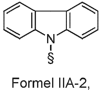 oder einer chemischen Struktur der Formel IIB-2
 wobei RN# ausgewählt ist aus der Gruppe bestehend aus Me, iPr, tBu, CN, CF3 und Ph;wobei § die Bindungsstelle einer Einfachbindung darstellt undwobei Rb bei jedem Auftreten unabhängig voneinander ausgewählt aus der Gruppe bestehend aus:H,Me,iPr,tBu,CN,CF3,Ph, das optional substituiert ist mit einem oder mehreren Substituenten unabhängig ausgewählt aus der Gruppe bestehend aus Me, iPr, tBu, CN, CF3 und Ph,Pyridinyl, das optional substituiert ist mit einem oder mehreren Substituenten unabhängig ausgewählt aus der Gruppe bestehend aus Me, iPr, tBu, CN, CF3 und Ph,Pyrimidinyl, das optional substituiert ist mit einem oder mehreren Substituenten unabhängig ausgewählt aus der Gruppe bestehend aus Me, iPr, tBu, CN, CF3 und Ph,Carbazolyl, das optional substituiert ist mit einem oder mehreren Substituenten unabhängig ausgewählt aus der Gruppe bestehend aus Me, iPr, tBu, CN, CF3 und Ph,Triazinyl, das optional substituiert ist mit einem oder mehreren Substituenten unabhängig ausgewählt aus der Gruppe bestehend aus Me, iPr, tBu, CN, CF3 und Ph,und N(Ph)2.
 - Organisches Molekül nach Anspruch 1, wobei R1 bei jedem Auftreten unabhängig voneinander Phenyl, das optional substituiert ist mit einem oder mehreren Substituenten R6, ist undR2 bei jedem Auftreten unabhängig voneinander ausgewählt ist aus der Gruppe bestehend aus Wasserstoff,CN,CF3 undPhenyl, das optional substituiert ist mit einem oder mehreren Substituenten R6.
- Organisches Molekül nach Anspruch 1 oder 2, aufweisend eine Struktur, ausgewählt aus der nachfolgend dargestellten Gruppe:


- Organisches Molekül nach einem oder mehreren der Ansprüche 1 bis 3, wobei Rb bei jedem Auftreten unabhängig ausgewählt ist aus der Gruppe bestehend aus H und CN.
- Organisches Molekül nach einem oder mehreren der Ansprüche 1 bis 4, aufweisend oder bestehend aus einer Struktur, ausgewählt aus der nachfolgend dargestellten Gruppe:


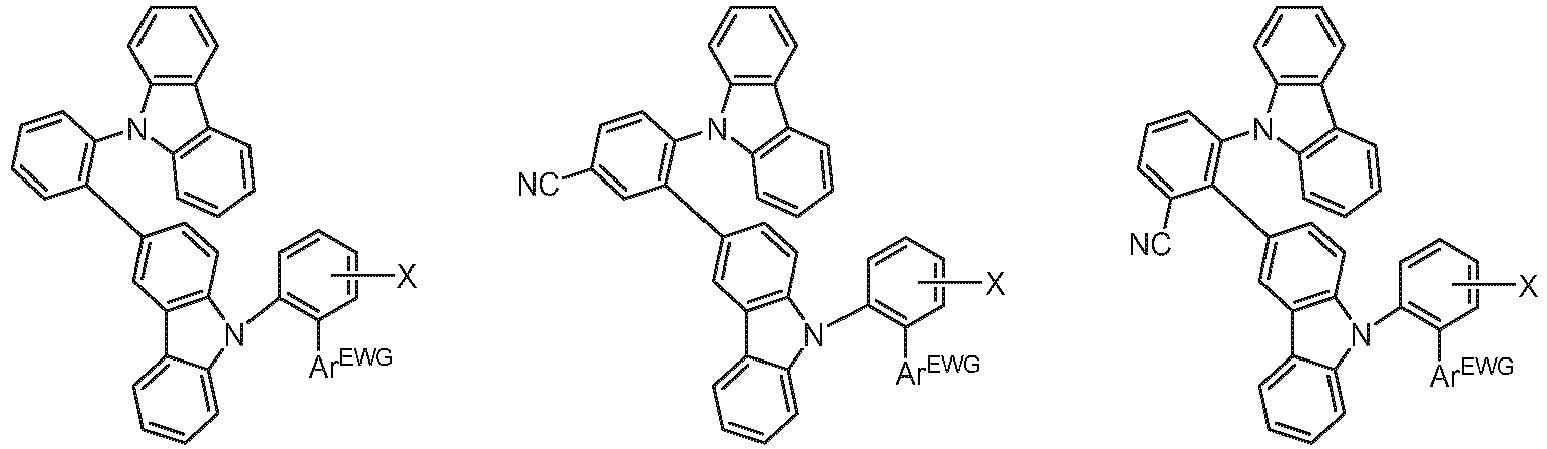


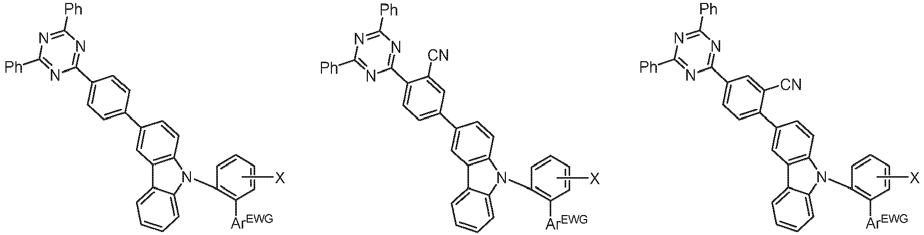


- Verfahren zur Herstellung eines organischen Moleküls nach Anspruch 1 bis 5, aufweisend den Schritt der Bereitstellung eines 6-RB-substituierten 3-Bromocarbazols als Reaktant.
- Verwendung eines Moleküls nach einem oder mehrerer der Ansprüche 1 bis 5 als Lumineszenzemitter und/oder Transportmaterial und/oder Lochinjektionsmaterial und/oder Lochblockiermaterial in einer optoelektronischen Vorrichtung.
- Verwendung nach Anspruch 7, wobei die optoelektronische Vorrichtung ausgewählt ist aus der Gruppe bestehend aus:• organischen lichtemittierenden Dioden (OLEDs),• lichtemittierenden elektrochemischen Zellen,• OLED-Sensoren,• organischen Dioden,• organischen Solarzellen,• organischen Transistoren,• organischen Feldeffekttransistoren,• organischen Lasern und• Down-Konversionselementen.
- Zusammensetzung, aufweisend:(a) ein organisches Molekül nach einem oder mehreren der Ansprüche 1 bis 5, insbesondere in Form eines Emitters, und(b) ein Emitter- und/oder Hostmaterial, das sich von dem organischen Molekül nach einem oder mehreren der Ansprüche 1 bis 5 unterscheidet, und(c) optional einen Farbstoff und/oder ein Lösungsmittel.
- Optoelektronische Vorrichtung, aufweisend ein organisches Molekül nach einem oder mehreren der Ansprüche 1 bis 5 oder eine Zusammensetzung nach Anspruch 9, insbesondere in Form einer Vorrichtung ausgewählt aus der Gruppe bestehend aus organischer lichtemittierender Diode (OLED), lichtemittierender elektrochemischer Zelle, OLED-Sensor, organischer Diode, organischer Solarzelle, organischem Transistor, organischem Feldeffekttransistor, organischem Laser und Down-Konversionselement.
- Optoelektronische Vorrichtung nach Anspruch 10, aufweisend- ein Substrat,- eine Anode und- eine Kathode, wobei die Anode oder die Kathode auf dem Substrat angeordnet sind, und- eine lichtemittierende Schicht, die zwischen der Anode und der Kathode angeordnet ist und die ein organisches Molekül gemäß einem oder mehreren der Ansprüche 1 bis 5 oder eine Zusammensetzung nach Anspruch 9 aufweist.
- Verfahren zur Herstellung einer optoelektronischen Vorrichtung, wobei ein organisches Molekül nach einem oder mehreren der Ansprüche 1 bis 5 oder eine Zusammensetzung nach Anspruch 9 verwendet wird.
- Verfahren nach Anspruch 12, aufweisend das Verarbeiten des organischen Moleküls oder der organischen Zusammensetzung durch ein Vakuumverdampfungsverfahren oder aus einer Lösung.
Applications Claiming Priority (4)
| Application Number | Priority Date | Filing Date | Title |
|---|---|---|---|
| EP18206790 | 2018-11-16 | ||
| EP18001020 | 2018-12-28 | ||
| EP18001022 | 2018-12-28 | ||
| PCT/EP2019/080654 WO2020099259A1 (de) | 2018-11-16 | 2019-11-08 | Carbazolderivate zur verwendung in optoelektronischen vorrichtungen |
Publications (2)
| Publication Number | Publication Date |
|---|---|
| EP3880672A1 EP3880672A1 (de) | 2021-09-22 |
| EP3880672B1 true EP3880672B1 (de) | 2024-10-23 |
Family
ID=68762689
Family Applications (1)
| Application Number | Title | Priority Date | Filing Date |
|---|---|---|---|
| EP19813240.9A Active EP3880672B1 (de) | 2018-11-16 | 2019-11-08 | Carbazolderivate zur verwendung in optoelektronischen vorrichtungen |
Country Status (4)
| Country | Link |
|---|---|
| US (1) | US20220131080A1 (de) |
| EP (1) | EP3880672B1 (de) |
| CN (1) | CN113015727A (de) |
| WO (1) | WO2020099259A1 (de) |
Families Citing this family (2)
| Publication number | Priority date | Publication date | Assignee | Title |
|---|---|---|---|---|
| KR102928186B1 (ko) * | 2020-07-17 | 2026-02-19 | (주)피엔에이치테크 | 유기발광 화합물 및 이를 포함하는 유기발광소자 |
| KR102791287B1 (ko) * | 2020-12-21 | 2025-04-08 | 엘티소재주식회사 | 헤테로고리 화합물, 이를 포함하는 유기 발광 소자, 이의 제조 방법 및 유기물층용 조성물 |
Family Cites Families (10)
| Publication number | Priority date | Publication date | Assignee | Title |
|---|---|---|---|---|
| DE102009053382A1 (de) * | 2009-11-14 | 2011-05-19 | Merck Patent Gmbh | Materialien für elektronische Vorrichtungen |
| KR20130078437A (ko) * | 2011-12-30 | 2013-07-10 | 제일모직주식회사 | 유기광전자소자용 화합물, 이를 포함하는 유기발광소자 및 상기 유기발광소자를 포함하는 표시장치 |
| KR20140096182A (ko) * | 2012-05-02 | 2014-08-04 | 롬엔드하스전자재료코리아유한회사 | 신규한 유기 전계 발광 화합물 및 이를 채용하고 있는 유기 전계 발광 소자 |
| WO2015142036A1 (en) * | 2014-03-17 | 2015-09-24 | Rohm And Haas Electronic Materials Korea Ltd. | Electron buffering material and organic electroluminescent device comprising the same |
| KR20150108330A (ko) * | 2014-03-17 | 2015-09-25 | 롬엔드하스전자재료코리아유한회사 | 전자 버퍼 재료 및 이를 포함하는 유기 전계 발광 소자 |
| WO2016013875A1 (en) * | 2014-07-22 | 2016-01-28 | Rohm And Haas Electronic Materials Korea Ltd. | Organic electroluminescent device |
| KR102502306B1 (ko) * | 2014-07-22 | 2023-02-23 | 롬엔드하스전자재료코리아유한회사 | 유기 전계 발광 소자 |
| US10062852B2 (en) * | 2015-06-23 | 2018-08-28 | Samsung Electronics Co., Ltd. | Condensed cyclic compound and organic light-emitting device including the same |
| TWI746682B (zh) * | 2016-11-01 | 2021-11-21 | 德商賽諾拉公司 | 有機分子,尤其是用於有機光電子裝置者 |
| KR101926771B1 (ko) * | 2018-03-02 | 2018-12-07 | 주식회사 진웅산업 | 열활성지연형광 특성을 갖는 인광 그린호스트 물질을 포함하는 유기발광소자 |
-
2019
- 2019-11-08 EP EP19813240.9A patent/EP3880672B1/de active Active
- 2019-11-08 US US17/294,453 patent/US20220131080A1/en active Pending
- 2019-11-08 CN CN201980074958.6A patent/CN113015727A/zh active Pending
- 2019-11-08 WO PCT/EP2019/080654 patent/WO2020099259A1/de not_active Ceased
Non-Patent Citations (1)
| Title |
|---|
| PALOMA L DOS SANTOS: "Triazatruxene: A Rigid Central Donor Unit for a D-A3 Thermally Activated Delayed Fluorescence Material Exhibiting Sub-Microsecond Reverse Intersystem Crossing and Unity Quantum Yield via Multiple Singlet-Triplet State Pairs", ADVANCED SCIENCE, 16 April 2018 (2018-04-16), pages 1 - 9, XP093152628, Retrieved from the Internet <URL:https://onlinelibrary.wiley.com/doi/epdf/10.1002/advs.201700989> * |
Also Published As
| Publication number | Publication date |
|---|---|
| US20220131080A1 (en) | 2022-04-28 |
| CN113015727A (zh) | 2021-06-22 |
| WO2020099259A1 (de) | 2020-05-22 |
| EP3880672A1 (de) | 2021-09-22 |
Similar Documents
| Publication | Publication Date | Title |
|---|---|---|
| DE102017109593B4 (de) | Organische Moleküle, insbesondere zur Verwendung in optoelektronischen Vorrichtungen | |
| EP3315581B1 (de) | Organische moleküle, insbesondere zur verwendung in organischen optoelektronischen vorrichtungen | |
| EP3287451B1 (de) | Organische moleküle, insbesondere zur verwendung in organischen optoelektronischen vorrichtungen | |
| EP3507285B1 (de) | Organische moleküle, insbesondere zur verwendung in organischen optoelektronischen vorrichtungen | |
| EP3530659A1 (de) | Organische moleküle, insbesondere zur verwendung in opto-elektronischen vorrichtungen | |
| EP3696246B1 (de) | Organische moleküle für opto-elektronische vorrichtungen | |
| DE102017114250B3 (de) | Organische Moleküle, insbesondere zur Verwendung in optoelektronischen Vorrichtungen | |
| WO2020135953A1 (en) | Organic molecules for optoelectronic devices | |
| EP3478657B1 (de) | Dicarbazolbiphenylderivate zur verwendung in optoelektronischen vorrichtungen | |
| EP3585777B1 (de) | Organische moleküle, insbesondere zur verwendung in organischen optoelektronischen vorrichtungen | |
| DE102017114372B3 (de) | Organische moleküle, insbesondere zur verwendung in optoelektronischen vorrichtungen | |
| EP3478656A1 (de) | Dicarbazolbiphenylderivate zur verwendung in optoelektronischen vorrichtungen | |
| DE102018114290B3 (de) | Organische Moleküle, insbesondere zur Verwendung in optoelektronischen Vorrichtungen | |
| EP3642183B1 (de) | Organische moleküle, insbesondere zur verwendung in optoelektronischen vorrichtungen | |
| DE102017122471B3 (de) | Organische moleküle, insbesondere zur verwendung in optoelektronischen vorrichtungen | |
| EP3392247B1 (de) | Organische moleküle, insbesondere zur verwendung in opto-elektronischen vorrichtungen | |
| EP3385264B1 (de) | Organische moleküle, insbesondere zur verwendung in organischen optoelektronischen vorrichtungen | |
| EP3279193B1 (de) | Phthalimid und carbazol oder dessen analoge enthaltende verbindungen zur verwendung in organischen optoelektronischen vorrichtungen | |
| DE102018126408B3 (de) | Organische Moleküle zur Verwendung in optoelektronischen Vorrichtungen | |
| EP3880672A1 (de) | Carbazolderivate zur verwendung in optoelektronischen vorrichtungen | |
| EP3581632B1 (de) | Organische moleküle für optoelektronische vorrichtungen | |
| DE102018107166B4 (de) | Organische Moleküle, insbesondere für die Verwendung in optoelektronischen Vorrichtungen | |
| EP3724181B1 (de) | Organische moleküle mit einem trifluormethyl-biphenyl-kern zur verwendung bei optoelektronischen vorrichtungen | |
| DE102017119592B3 (de) | Organische Moleküle, insbesondere zur Verwendung in optoelektronischen Vorrichtungen | |
| EP3399004B1 (de) | Organische moleküle, insbesondere zur verwendung in optoelektronischen vorrichtungen |
Legal Events
| Date | Code | Title | Description |
|---|---|---|---|
| STAA | Information on the status of an ep patent application or granted ep patent |
Free format text: STATUS: UNKNOWN |
|
| STAA | Information on the status of an ep patent application or granted ep patent |
Free format text: STATUS: THE INTERNATIONAL PUBLICATION HAS BEEN MADE |
|
| PUAI | Public reference made under article 153(3) epc to a published international application that has entered the european phase |
Free format text: ORIGINAL CODE: 0009012 |
|
| STAA | Information on the status of an ep patent application or granted ep patent |
Free format text: STATUS: REQUEST FOR EXAMINATION WAS MADE |
|
| 17P | Request for examination filed |
Effective date: 20210615 |
|
| AK | Designated contracting states |
Kind code of ref document: A1 Designated state(s): AL AT BE BG CH CY CZ DE DK EE ES FI FR GB GR HR HU IE IS IT LI LT LU LV MC MK MT NL NO PL PT RO RS SE SI SK SM TR |
|
| DAV | Request for validation of the european patent (deleted) | ||
| DAX | Request for extension of the european patent (deleted) | ||
| STAA | Information on the status of an ep patent application or granted ep patent |
Free format text: STATUS: EXAMINATION IS IN PROGRESS |
|
| 17Q | First examination report despatched |
Effective date: 20220620 |
|
| RAP1 | Party data changed (applicant data changed or rights of an application transferred) |
Owner name: SAMSUNG DISPLAY CO., LTD. |
|
| P01 | Opt-out of the competence of the unified patent court (upc) registered |
Effective date: 20230516 |
|
| GRAP | Despatch of communication of intention to grant a patent |
Free format text: ORIGINAL CODE: EPIDOSNIGR1 |
|
| STAA | Information on the status of an ep patent application or granted ep patent |
Free format text: STATUS: GRANT OF PATENT IS INTENDED |
|
| RIC1 | Information provided on ipc code assigned before grant |
Ipc: H10K 85/60 20230101ALI20240423BHEP Ipc: H10K 50/11 20230101ALI20240423BHEP Ipc: C07D 403/14 20060101AFI20240423BHEP |
|
| INTG | Intention to grant announced |
Effective date: 20240524 |
|
| GRAS | Grant fee paid |
Free format text: ORIGINAL CODE: EPIDOSNIGR3 |
|
| GRAA | (expected) grant |
Free format text: ORIGINAL CODE: 0009210 |
|
| STAA | Information on the status of an ep patent application or granted ep patent |
Free format text: STATUS: THE PATENT HAS BEEN GRANTED |
|
| AK | Designated contracting states |
Kind code of ref document: B1 Designated state(s): AL AT BE BG CH CY CZ DE DK EE ES FI FR GB GR HR HU IE IS IT LI LT LU LV MC MK MT NL NO PL PT RO RS SE SI SK SM TR |
|
| REG | Reference to a national code |
Ref country code: GB Ref legal event code: FG4D Free format text: NOT ENGLISH |
|
| REG | Reference to a national code |
Ref country code: CH Ref legal event code: EP |
|
| REG | Reference to a national code |
Ref country code: DE Ref legal event code: R096 Ref document number: 502019012360 Country of ref document: DE |
|
| REG | Reference to a national code |
Ref country code: IE Ref legal event code: FG4D Free format text: LANGUAGE OF EP DOCUMENT: GERMAN |
|
| REG | Reference to a national code |
Ref country code: LT Ref legal event code: MG9D |
|
| REG | Reference to a national code |
Ref country code: NL Ref legal event code: MP Effective date: 20241023 |
|
| PG25 | Lapsed in a contracting state [announced via postgrant information from national office to epo] |
Ref country code: NL Free format text: LAPSE BECAUSE OF FAILURE TO SUBMIT A TRANSLATION OF THE DESCRIPTION OR TO PAY THE FEE WITHIN THE PRESCRIBED TIME-LIMIT Effective date: 20241023 |
|
| PG25 | Lapsed in a contracting state [announced via postgrant information from national office to epo] |
Ref country code: NL Free format text: LAPSE BECAUSE OF FAILURE TO SUBMIT A TRANSLATION OF THE DESCRIPTION OR TO PAY THE FEE WITHIN THE PRESCRIBED TIME-LIMIT Effective date: 20241023 |
|
| PG25 | Lapsed in a contracting state [announced via postgrant information from national office to epo] |
Ref country code: HR Free format text: LAPSE BECAUSE OF FAILURE TO SUBMIT A TRANSLATION OF THE DESCRIPTION OR TO PAY THE FEE WITHIN THE PRESCRIBED TIME-LIMIT Effective date: 20241023 Ref country code: PT Free format text: LAPSE BECAUSE OF FAILURE TO SUBMIT A TRANSLATION OF THE DESCRIPTION OR TO PAY THE FEE WITHIN THE PRESCRIBED TIME-LIMIT Effective date: 20250224 Ref country code: IS Free format text: LAPSE BECAUSE OF FAILURE TO SUBMIT A TRANSLATION OF THE DESCRIPTION OR TO PAY THE FEE WITHIN THE PRESCRIBED TIME-LIMIT Effective date: 20250223 |
|
| PG25 | Lapsed in a contracting state [announced via postgrant information from national office to epo] |
Ref country code: FI Free format text: LAPSE BECAUSE OF FAILURE TO SUBMIT A TRANSLATION OF THE DESCRIPTION OR TO PAY THE FEE WITHIN THE PRESCRIBED TIME-LIMIT Effective date: 20241023 |
|
| PG25 | Lapsed in a contracting state [announced via postgrant information from national office to epo] |
Ref country code: BG Free format text: LAPSE BECAUSE OF FAILURE TO SUBMIT A TRANSLATION OF THE DESCRIPTION OR TO PAY THE FEE WITHIN THE PRESCRIBED TIME-LIMIT Effective date: 20241023 |
|
| PG25 | Lapsed in a contracting state [announced via postgrant information from national office to epo] |
Ref country code: ES Free format text: LAPSE BECAUSE OF FAILURE TO SUBMIT A TRANSLATION OF THE DESCRIPTION OR TO PAY THE FEE WITHIN THE PRESCRIBED TIME-LIMIT Effective date: 20241023 |
|
| PG25 | Lapsed in a contracting state [announced via postgrant information from national office to epo] |
Ref country code: NO Free format text: LAPSE BECAUSE OF FAILURE TO SUBMIT A TRANSLATION OF THE DESCRIPTION OR TO PAY THE FEE WITHIN THE PRESCRIBED TIME-LIMIT Effective date: 20250123 |
|
| PG25 | Lapsed in a contracting state [announced via postgrant information from national office to epo] |
Ref country code: LV Free format text: LAPSE BECAUSE OF FAILURE TO SUBMIT A TRANSLATION OF THE DESCRIPTION OR TO PAY THE FEE WITHIN THE PRESCRIBED TIME-LIMIT Effective date: 20241023 Ref country code: GR Free format text: LAPSE BECAUSE OF FAILURE TO SUBMIT A TRANSLATION OF THE DESCRIPTION OR TO PAY THE FEE WITHIN THE PRESCRIBED TIME-LIMIT Effective date: 20250124 |
|
| PG25 | Lapsed in a contracting state [announced via postgrant information from national office to epo] |
Ref country code: PL Free format text: LAPSE BECAUSE OF FAILURE TO SUBMIT A TRANSLATION OF THE DESCRIPTION OR TO PAY THE FEE WITHIN THE PRESCRIBED TIME-LIMIT Effective date: 20241023 |
|
| PG25 | Lapsed in a contracting state [announced via postgrant information from national office to epo] |
Ref country code: RS Free format text: LAPSE BECAUSE OF FAILURE TO SUBMIT A TRANSLATION OF THE DESCRIPTION OR TO PAY THE FEE WITHIN THE PRESCRIBED TIME-LIMIT Effective date: 20250123 |
|
| REG | Reference to a national code |
Ref country code: CH Ref legal event code: PL |
|
| PG25 | Lapsed in a contracting state [announced via postgrant information from national office to epo] |
Ref country code: SM Free format text: LAPSE BECAUSE OF FAILURE TO SUBMIT A TRANSLATION OF THE DESCRIPTION OR TO PAY THE FEE WITHIN THE PRESCRIBED TIME-LIMIT Effective date: 20241023 |
|
| PG25 | Lapsed in a contracting state [announced via postgrant information from national office to epo] |
Ref country code: MC Free format text: LAPSE BECAUSE OF FAILURE TO SUBMIT A TRANSLATION OF THE DESCRIPTION OR TO PAY THE FEE WITHIN THE PRESCRIBED TIME-LIMIT Effective date: 20241023 |
|
| PG25 | Lapsed in a contracting state [announced via postgrant information from national office to epo] |
Ref country code: DK Free format text: LAPSE BECAUSE OF FAILURE TO SUBMIT A TRANSLATION OF THE DESCRIPTION OR TO PAY THE FEE WITHIN THE PRESCRIBED TIME-LIMIT Effective date: 20241023 |
|
| PG25 | Lapsed in a contracting state [announced via postgrant information from national office to epo] |
Ref country code: LU Free format text: LAPSE BECAUSE OF NON-PAYMENT OF DUE FEES Effective date: 20241108 |
|
| REG | Reference to a national code |
Ref country code: CH Ref legal event code: PL |
|
| PG25 | Lapsed in a contracting state [announced via postgrant information from national office to epo] |
Ref country code: EE Free format text: LAPSE BECAUSE OF FAILURE TO SUBMIT A TRANSLATION OF THE DESCRIPTION OR TO PAY THE FEE WITHIN THE PRESCRIBED TIME-LIMIT Effective date: 20241023 |
|
| PG25 | Lapsed in a contracting state [announced via postgrant information from national office to epo] |
Ref country code: CH Free format text: LAPSE BECAUSE OF NON-PAYMENT OF DUE FEES Effective date: 20241130 |
|
| PG25 | Lapsed in a contracting state [announced via postgrant information from national office to epo] |
Ref country code: RO Free format text: LAPSE BECAUSE OF FAILURE TO SUBMIT A TRANSLATION OF THE DESCRIPTION OR TO PAY THE FEE WITHIN THE PRESCRIBED TIME-LIMIT Effective date: 20241023 |
|
| REG | Reference to a national code |
Ref country code: DE Ref legal event code: R097 Ref document number: 502019012360 Country of ref document: DE |
|
| PG25 | Lapsed in a contracting state [announced via postgrant information from national office to epo] |
Ref country code: SK Free format text: LAPSE BECAUSE OF FAILURE TO SUBMIT A TRANSLATION OF THE DESCRIPTION OR TO PAY THE FEE WITHIN THE PRESCRIBED TIME-LIMIT Effective date: 20241023 |
|
| PG25 | Lapsed in a contracting state [announced via postgrant information from national office to epo] |
Ref country code: CZ Free format text: LAPSE BECAUSE OF FAILURE TO SUBMIT A TRANSLATION OF THE DESCRIPTION OR TO PAY THE FEE WITHIN THE PRESCRIBED TIME-LIMIT Effective date: 20241023 |
|
| PG25 | Lapsed in a contracting state [announced via postgrant information from national office to epo] |
Ref country code: IT Free format text: LAPSE BECAUSE OF FAILURE TO SUBMIT A TRANSLATION OF THE DESCRIPTION OR TO PAY THE FEE WITHIN THE PRESCRIBED TIME-LIMIT Effective date: 20241023 |
|
| REG | Reference to a national code |
Ref country code: BE Ref legal event code: MM Effective date: 20241130 |
|
| PLBE | No opposition filed within time limit |
Free format text: ORIGINAL CODE: 0009261 |
|
| STAA | Information on the status of an ep patent application or granted ep patent |
Free format text: STATUS: NO OPPOSITION FILED WITHIN TIME LIMIT |
|
| PG25 | Lapsed in a contracting state [announced via postgrant information from national office to epo] |
Ref country code: SE Free format text: LAPSE BECAUSE OF FAILURE TO SUBMIT A TRANSLATION OF THE DESCRIPTION OR TO PAY THE FEE WITHIN THE PRESCRIBED TIME-LIMIT Effective date: 20241023 |
|
| 26N | No opposition filed |
Effective date: 20250724 |
|
| PG25 | Lapsed in a contracting state [announced via postgrant information from national office to epo] |
Ref country code: BE Free format text: LAPSE BECAUSE OF NON-PAYMENT OF DUE FEES Effective date: 20241130 |
|
| PG25 | Lapsed in a contracting state [announced via postgrant information from national office to epo] |
Ref country code: IE Free format text: LAPSE BECAUSE OF NON-PAYMENT OF DUE FEES Effective date: 20241108 |
|
| PGFP | Annual fee paid to national office [announced via postgrant information from national office to epo] |
Ref country code: DE Payment date: 20251020 Year of fee payment: 7 |
|
| PGFP | Annual fee paid to national office [announced via postgrant information from national office to epo] |
Ref country code: GB Payment date: 20251023 Year of fee payment: 7 |
|
| PG25 | Lapsed in a contracting state [announced via postgrant information from national office to epo] |
Ref country code: AT Free format text: LAPSE BECAUSE OF NON-PAYMENT OF DUE FEES Effective date: 20241108 |
|
| PGFP | Annual fee paid to national office [announced via postgrant information from national office to epo] |
Ref country code: FR Payment date: 20251021 Year of fee payment: 7 |
|
| REG | Reference to a national code |
Ref country code: AT Ref legal event code: MM01 Ref document number: 1734762 Country of ref document: AT Kind code of ref document: T Effective date: 20241108 |
|
| PG25 | Lapsed in a contracting state [announced via postgrant information from national office to epo] |
Ref country code: HU Free format text: LAPSE BECAUSE OF FAILURE TO SUBMIT A TRANSLATION OF THE DESCRIPTION OR TO PAY THE FEE WITHIN THE PRESCRIBED TIME-LIMIT; INVALID AB INITIO Effective date: 20191108 |
|
| PG25 | Lapsed in a contracting state [announced via postgrant information from national office to epo] |
Ref country code: CY Free format text: LAPSE BECAUSE OF FAILURE TO SUBMIT A TRANSLATION OF THE DESCRIPTION OR TO PAY THE FEE WITHIN THE PRESCRIBED TIME-LIMIT; INVALID AB INITIO Effective date: 20191108 |