EP3880499B1 - Kupplungseinrichtung für einen fahrwerksaktuator und fahrwerksaktuator - Google Patents
Kupplungseinrichtung für einen fahrwerksaktuator und fahrwerksaktuator Download PDFInfo
- Publication number
- EP3880499B1 EP3880499B1 EP19794435.8A EP19794435A EP3880499B1 EP 3880499 B1 EP3880499 B1 EP 3880499B1 EP 19794435 A EP19794435 A EP 19794435A EP 3880499 B1 EP3880499 B1 EP 3880499B1
- Authority
- EP
- European Patent Office
- Prior art keywords
- clutch
- drive
- chassis
- chassis actuator
- run
- Prior art date
- Legal status (The legal status is an assumption and is not a legal conclusion. Google has not performed a legal analysis and makes no representation as to the accuracy of the status listed.)
- Active
Links
Images

Classifications
-
- B—PERFORMING OPERATIONS; TRANSPORTING
- B60—VEHICLES IN GENERAL
- B60G—VEHICLE SUSPENSION ARRANGEMENTS
- B60G21/00—Interconnection systems for two or more resiliently-suspended wheels, e.g. for stabilising a vehicle body with respect to acceleration, deceleration or centrifugal forces
- B60G21/02—Interconnection systems for two or more resiliently-suspended wheels, e.g. for stabilising a vehicle body with respect to acceleration, deceleration or centrifugal forces permanently interconnected
- B60G21/04—Interconnection systems for two or more resiliently-suspended wheels, e.g. for stabilising a vehicle body with respect to acceleration, deceleration or centrifugal forces permanently interconnected mechanically
- B60G21/05—Interconnection systems for two or more resiliently-suspended wheels, e.g. for stabilising a vehicle body with respect to acceleration, deceleration or centrifugal forces permanently interconnected mechanically between wheels on the same axle but on different sides of the vehicle, i.e. the left and right wheel suspensions being interconnected
- B60G21/055—Stabiliser bars
- B60G21/0551—Mounting means therefor
- B60G21/0553—Mounting means therefor adjustable
- B60G21/0556—Mounting means therefor adjustable including a releasable coupling
-
- F—MECHANICAL ENGINEERING; LIGHTING; HEATING; WEAPONS; BLASTING
- F16—ENGINEERING ELEMENTS AND UNITS; GENERAL MEASURES FOR PRODUCING AND MAINTAINING EFFECTIVE FUNCTIONING OF MACHINES OR INSTALLATIONS; THERMAL INSULATION IN GENERAL
- F16D—COUPLINGS FOR TRANSMITTING ROTATION; CLUTCHES; BRAKES
- F16D43/00—Automatic clutches
- F16D43/02—Automatic clutches actuated entirely mechanically
- F16D43/20—Automatic clutches actuated entirely mechanically controlled by torque, e.g. overload-release clutches, slip-clutches with means by which torque varies the clutching pressure
- F16D43/21—Automatic clutches actuated entirely mechanically controlled by torque, e.g. overload-release clutches, slip-clutches with means by which torque varies the clutching pressure with friction members
- F16D43/213—Automatic clutches actuated entirely mechanically controlled by torque, e.g. overload-release clutches, slip-clutches with means by which torque varies the clutching pressure with friction members with axially applied torque-limiting friction surfaces
- F16D43/218—Automatic clutches actuated entirely mechanically controlled by torque, e.g. overload-release clutches, slip-clutches with means by which torque varies the clutching pressure with friction members with axially applied torque-limiting friction surfaces with conical friction surfaces
Definitions
- the invention relates to a chassis actuator for an adjustable roll stabilizer of a motor vehicle according to claim 1.
- this is a substantially C-shaped torsion bar spring, which is rotatably mounted in the central area relative to the body and whose outer, opposite ends are each coupled to a wheel suspension. Thanks to this design, the roll stabilizer ensures that the body of the vehicle not only deflects on the outside side of the curve when cornering (due to the centrifugal force), but also that the wheel on the inside of the curve is lowered slightly (copy behavior).
- the roll stabilizer can be divided into two stabilizer sections, which can be rotated relative to one another about an axis of rotation by means of an actuator acting between them. By rotating the stabilizer sections relative to one another, a rolling movement of the vehicle body is specifically generated or a rolling movement of the vehicle body caused by external influences is specifically counteracted.
- Adjustable roll stabilizers are known, the actuator of which has a drive train formed from an electric drive motor and a gearbox. While the drive motor is mounted fixed to the housing and is connected in a rotationally fixed manner to a stabilizer section, the output-side output of the gearbox of the actuator is connected in a rotationally fixed manner to the other stabilizer section, so that the drive train formed from the drive motor and gearbox acts between the two stabilizer sections.
- the size of the electric motor is reasonable
- a mechanical gear is usually used for the actuator, in particular in the form of a single-stage or multi-stage planetary gear to translate the torque or the speed of the drive motor.
- planetary gears have a centrally arranged sun gear, a set of planetary gears and a ring gear.
- the planet gears are each rotatable about their own axis of rotation relative to a planet carrier. All planet carriers are in meshing engagement and roll on the centrally arranged sun gear.
- the planet gears are in meshing engagement and roll on an outer ring gear, which in the case of a roll stabilizer is usually fixed to the housing, that is, designed as part of the housing of the actuator.
- a coupling device according to individual features of claim 1 is known, which - as it is mentioned in the introduction there (column 2, lines 19-53) - can be used as a safety coupling in an extruder drive in plastics processing.
- One of the contact surfaces of the coupling is connected to the associated coupling part via a shape-changing activation member made of a metal alloy with shape memory.
- the activation element deforms under the influence of temperature, which means that the clutch can be switched thermally (cancelled).
- the coupling device has an axially displaceable clamping ring. This is axially prestressed by means of a compression spring designed as a plate spring and forms together with a coupling cone, a keyway into which a friction body is inserted (see column 4, lines 50-61 there).
- a coupling device for a (passive) roll stabilizer is known.
- This has a locking device in the form of a rotary friction clutch, with which an area of the stabilizer can be locked relative to the body of the vehicle.
- a torsion spring unit with a spring element and a structurally stable housing can apply torsional force by switching it on or off.
- DE 10 2004 004 931 A1 generally discloses a clutch device in the form of a multi-plate clutch. This can be operated using an axial adjustment device.
- EP 3 156 271 B1 discloses a roll stabilizer for a motor vehicle. This is a passive roll stabilizer (not actively adjustable using a drive motor). The two stabilizer sections of the roll stabilizer are connected to one another via a switchable clutch.
- the coupling device of the chassis actuator according to the invention thus enables the chassis actuator to be operated in two states.
- transmission state active state
- the frictional connection there is a drive connection between the drive shaft, which corresponds, for example, to the output shaft of a drive motor of the chassis actuator, and the output element of the clutch device, which, for example, forms an input element of a gearbox of the chassis actuator.
- the coupling device By switching the coupling device, actuated by axial displacement of the coupling element, it is thus advantageously possible to operate the chassis actuator either with an existing mechanical drive connection between the drive motor and transmission or - in the decoupling state - to cancel this mechanical drive connection or at least to reduce it so that it can be reached from the outside
- the transmission causes disturbances affecting the chassis actuator (speed fluctuations, torque fluctuations, load changes) to be kept away from the drive motor.
- a starting element is assigned to the drive shaft, in particular attached thereto, which has a starting contour facing the coupling element on the end face, which is designed such that a relative rotation of the starting element relative to the coupling element causes axial displacement of the coupling element.
- the starting contour provided on the starting element ensures that a rotation of the drive shaft (rotation) can be converted into an axial displacement (translation) of the coupling element.
- the starting contour formed on the starting element is expediently designed to be complementary to a starting contour which is formed on a surface of the coupling element facing the starting element.
- the starting contour expediently has, at least in some areas, a surface section that is oblique relative to the radial plane, which ensures that when the starting contour of the starting element comes into contact with the starting contour of the coupling element on this oblique surface section, the rotational movement is converted into a translational movement.
- an advantageous development of the coupling device provides that the starting contour formed on the starting element has at least one axial elevation in relation to its circumferential course.
- the coupling device can be operated equally in both directions of rotation of the drive shaft, an advantageous development of the coupling device provides that the at least one axial elevation slopes equally in both circumferential directions to form an axial recess.
- the clutch actuation by the starting element can thus take place equally in both directions of rotation of the drive shaft.
- the coupling element can be designed in different ways. Expediently, it is a substantially rotationally symmetrical component, with an end face coupling surface of the coupling element facing the output element advantageously being conical.
- the coupling element and the output element are each provided with a coupling lining on mutually facing, in particular conical, surface areas. This ensures that a drive connection can be established between the coupling element and the output element by force-fitting, in which the coupling element is pressed against the output element in the axial direction. If the coupling force falls below the required coupling force, the non-positive drive connection is canceled; in this case, the coupling element and output element are decoupled from each other (decoupling state).
- the output element is advantageously mounted on the drive shaft so that it can be rotated, preferably also slightly axially displaceable, in particular by means of a roller bearing.
- a slight axial displaceability of the output element on the drive shaft is particularly useful if a counter-friction element is arranged on the drive shaft, on a side of the output element facing away from the coupling element, with the counter-friction element and the output element each on facing, in particular conical, surface areas are provided with a clutch lining.
- the output element When the coupling device is actuated (creation of the frictional connection), it is axially clamped between the coupling element and the counter-friction element, resulting in a particularly large usable coupling surface.
- the certain axial mobility of the output element ensures that equally high coupling forces arise on both sides of the output element.
- the output element is preferably a sun gear or part of a sun gear of a particularly multi-stage planetary gear.
- the coupling device is integrated into the planetary gear in a particularly space-saving manner.
- the coupling element is assigned means which axially prestress the coupling element relative to the output element.
- An at least slight axial preload of the coupling element relative to the output element ensures that in every operating state of the coupling device there is at least a slight frictional resistance between them, which is necessary to trigger the clutch.
- the preload can be achieved, for example, by a spring element which is supported axially on the drive shaft or on the starting element attached thereto in order to preload the coupling element in the axial direction against the output element.
- a chassis actuator for a motor vehicle according to the feature of claim 12.
- This is a chassis actuator for a motor vehicle, in particular an adjustable roll stabilizer, with a drive train having a drive motor and a transmission for driving at least one chassis component .
- the drive motor is preferably an electric motor.
- the chassis actuator is characterized by a clutch device of the previously described type arranged in the drive train, which can be switched between a transmission state (active state), in which there is a drive connection between the drive motor and an output of the transmission, and a decoupling state depending on the operating state of the drive motor (passive Condition) in which the drive connection is canceled or at least reduced.
- the coupling device used corresponds to the coupling device previously described with reference to claim 1, and can advantageously have the features explained in this context.
- the at least one chassis component is two stabilizer sections of an adjustable roll stabilizer.
- the chassis actuator is arranged to act between these two stabilizer sections in such a way that the stabilizer sections can be rotated relative to one another about an axis of rotation by means of the chassis actuator.
- the chassis actuator is advantageously designed in such a way that the coupling device can be switched by mechanical interaction of a motor-side starting element with a coupling element in such a way that the transmission state (active state) is present when the drive motor is in operation and the decoupling state (passive state) is present when the drive motor is at rest.
- the chassis actuator is therefore - depending on the switching state of the clutch device - either operable in the decoupling state, in which the vibrations introduced into the drive train via uneven road surfaces are decoupled from the drive motor, or in the transmission state of the chassis actuator, in which due to an existing drive connection between the drive motor and transmission and chassis component, the stabilizer sections can be rotated relative to one another about the axis of rotation by means of the drive train. In the latter (active) state, it is therefore possible for the drive motor to carry out a targeted intervention in the rolling behavior of the motor vehicle.
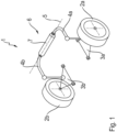
- FIG. 1 To illustrate the preferred area of application of the invention, an adjustable roll stabilizer 1 in a schematic view.
- the roll stabilizer 1 is part of a not completely shown chassis of a motor vehicle (not shown).
- a first wheel 2a and a second wheel 2b arranged on the opposite side of the vehicle are each connected to the body of the motor vehicle via a wheel suspension 3a, 3b shown in simplified form.
- Each of the wheel suspensions 3a, 3b is connected to one end of an associated stabilizer section 4a or 4b of the adjustable roll stabilizer 1.
- the two stabilizer sections 4a and 4b are connected to one another in the center of the vehicle via an actuator 6.
- the adjustable roll stabilizer 1 is mounted so that it can rotate relative to the vehicle body about an axis of rotation 5 (mounting not shown in more detail).
- the stabilizer sections 4a and 4b can be rotated relative to one another about the axis of rotation 5 depending on the direction of rotation of the electric motor.
- the roll stabilizer 1 can be adjusted in a manner known per se in order to specifically influence the roll behavior of the motor vehicle.
- the gear provided in the actuator 6 is typically designed as a multi-stage planetary gear.
- the output-side planetary gear stage which is connected in a rotationally fixed manner to the stabilizer section 4a, can be exposed to strong torsional vibrations (torques that vary greatly in type and magnitude) during operation of the motor vehicle. These are caused in particular by uneven road surfaces, which are introduced into the actuator via the chassis as a rotational movement of the stabilizer sections about the axis of rotation.
- the actuator 6 shown has a clutch device 10, which is described below using the Figures 2 to 5 needs to be explained in more detail.
- the Figures 2 to 5 refer to a first exemplary embodiment of the coupling device 10, the illustrations of Figures 2 and 5 each show the coupling device 10 in different states, while in the Figures 3 and 4 Details of the coupling device 10 are shown. Since the Figures 2 to 5 refer to a same embodiment of the coupling device 10, the same components in the figures are provided with the same reference numbers, and to avoid repetition it should be noted that the following explanations refer to the Figures 2 to 5 should be understood in the overall context.
- FIG. 2 shows Figure 2 in a highly simplified view a clutch device 10 according to an exemplary embodiment of the invention in the transmission state (active state).
- the clutch device 10 can be located in the drive train of an actuator of an adjustable roll stabilizer as in Figure 1 shown.
- an actuator has a drive train for driving at least one chassis component 4a, 4b in the form of a stabilizer section.
- the drive train comprising a drive motor 8 and, in particular, a multi-stage planetary gear
- the two stabilizer sections 4a, 4b can be rotated relative to one another about the axis of rotation 5.
- FIG. 2 shows a simplified representation of the clutch device 10 arranged in the drive train of an actuator, with the axis of rotation 5 being indicated for orientation.
- a drive motor 8 in the form of an electric motor has a motor shaft 9 on the output side, which is rotatably mounted via a bearing 24 within a housing (not shown) of the actuator.
- the coupling device 10 serves to be able to either establish or cancel or reduce a drive connection between the motor shaft 9 and an output element 15 of the coupling device 10. It is therefore a switchable clutch device 10.
- the output element 15 of the clutch device 10 is designed as a substantially rotationally symmetrical component (relative to the axis of rotation 5) and is rotatably mounted relative to the motor shaft 9.
- a needle bearing 12 is used for rotatable mounting.
- the output element 15 of the clutch device 10 also serves as an input element in a multi-stage planetary gear (not shown) of the actuator. Because the output element 15 of the clutch device 10 is a sun gear or part of a sun gear of the multi-stage planetary gear, an advantageous compact design is made possible for the actuator while ensuring functional integration (additional presence of a clutch).
- the output element 15 which is designed as a sun gear, has a conicity on its two inner end face areas, each of which is provided with a clutch lining 17.
- a cone 16 is arranged on the motor shaft 9 on the side of the sun gear 15 facing away from the drive motor 8. This is also provided with a clutch lining 19 and is arranged opposite the clutch lining 17 on the sun gear 15.
- An axially displaceable clutch disk 14 is arranged on the side of the sun gear 15 facing the drive motor 8.
- the clutch disc 14, shown individually in Figure 4 is designed as a substantially rotationally symmetrical component (relative to the axis of rotation 5) and has a conical end face on a side facing the sun gear 15, which is provided with a clutch lining 18.
- the clutch disk 14 is rotatably mounted relative to the motor shaft 9 and is also axially displaceable between a position in which the clutch disk 14 abuts a thrust disk 11 fixedly mounted on the motor shaft 9 and a position in which the clutch disk 14 with its clutch lining 18 against the Clutch lining 17 of sun gear 15 abuts.
- the thrust washer 11 is arranged on the motor shaft 9 in a rotationally fixed manner and ultimately, in cooperation with the clutch disk 14, fulfills the function: to mechanically actuate the clutch device 10 depending on the operating state of the drive motor 8.
- the thrust washer 11 has a thrust contour 22 on its side facing the clutch disk 14, which is designed such that a relative rotation of the thrust disk 11 - together with the motor shaft 9 - relative to the clutch disk 14 causes an axial displacement of the clutch disk 14.
- the start-up contour 22 formed on the stop washer 11 is designed to complement the start-up contour 23 (compare Figure 4 ), which is formed on the surface of the clutch disk 14 facing the thrust washer 11.
- the contact contour 22 formed on the thrust washer 11 has, in relation to its circumferential course, two axial elevations 20, which slope equally in both circumferential directions to an axial recess 21. According to representation by Figure 3 Only the front axial elevation 20 can be seen based on the perspective view; a second, rear axial elevation is covered by the motor shaft 9.
- the clutch device 10 Due to the shape of the thrust washer 11, in particular the thrust contour 22 provided thereon and the complementary thrust contour 23 on the clutch disk 14, a translational movement of the clutch disk 14 in the axial direction (onto the sun gear 15) can be achieved by rotating the thrust disk 11 via the motor shaft 9 to) effect. Since an axial displacement of the clutch disk 14, as already mentioned above, causes the clutch device 10 to be actuated (switching from the decoupling state to the transmission state), the clutch device 10 creates the possibility of establishing a drive connection between the motor shaft 9 and the sun gear, depending on the operating state of the drive motor 8 15 or to abolish or at least reduce them.
- a spring element 13 in the form of a coil spring is also arranged on the motor shaft 9.
- One end of the coil spring 13 rests axially on the thrust washer 11.
- the coil spring 13 lies with an opposite end - in the assembled state Figures 2 or 5 - on the clutch disc 14. Due to the installation situation, the coil spring 13 exerts an axial preload on the clutch disk 14, so that the Clutch disc 14 is at least slightly axially biased relative to the sun gear 15.
- the certain axial preload ensures that the clutch disk 14 is constantly in a certain frictional contact with the sun gear 15 (in this respect Figure 5 an exaggerated spacing purely for reasons of understanding) in order to prevent the clutch disc 14 from rotating freely with the thrust washer 11.
- the at least slightly always present frictional resistance between the sun gear 15 and the clutch disk 14 is therefore intended to ensure that the clutch disk 14, which is in the decoupling state, does not simply rotate with the thrust disk 11, which begins to rotate, when the electric motor 8 starts up, but rather through an initial relative rotation between the thrust disk 11 and clutch disk 14, the starting contours 22 and 23 on the thrust disk 11 and clutch disk 14 come into such engagement contact that an axial displacement of the clutch disk 14 in the direction of the sun gear 15 takes place.
- the coupling device 10 described in this way or a chassis actuator of an adjustable roll stabilizer provided with it offer the possibility of mechanically coupling the drive motor from the transmission or the chassis depending on the operating state of the drive motor.
- the clutch device is actuated purely mechanically without the aid of electrical devices and is therefore not susceptible to malfunctions in this regard.
- the integrated design enables a space-saving arrangement of the coupling device within the housing of the actuator.
- the possibility of decoupling makes it possible to advantageously reduce disruptive vibrations and thus disruptive noises that are caused in certain operating situations by movements of the chassis the actuator can be initiated.
- the design of the thrust disk 11 with a startup contour 22 provided thereon or the correspondingly complementary startup contour 23 on the clutch disk 14 enables the clutch device 10 to be actuated in both directions of rotation of the drive motor 8.
- the switching between the decoupling state and the transmission state is therefore independent of the direction, which means that it is used within of an adjustable roll stabilizer is important because its actuator is operated equally in both directions of rotation.
Landscapes
- Engineering & Computer Science (AREA)
- Mechanical Engineering (AREA)
- General Engineering & Computer Science (AREA)
- Vehicle Body Suspensions (AREA)
Description
- Die Erfindung betrifft einen Fahrwerksaktuator für einen verstellbaren Wankstabilisator eines Kraftfahrzeugs gemäß Anspruch 1.
- In der Fahrzeugtechnik, insbesondere der Fahrwerkstechnik ist es für sich gesehen bekannt, Fahrzeuge mit einem sogenannten Wankstabilisator auszustatten, um die dynamische Fahrzeugstabilität sowie den Fahrkomfort zu steigern. In einfachster Ausführung handelt es sich hierbei um eine im Wesentlichen C-förmige Drehstabfeder, die im mittigen Bereich drehbar gegenüber der Karosserie gelagert ist und deren äußere, sich gegenüberliegende Enden jeweils mit einer Radaufhängung gekoppelt sind. Durch diese Konstruktion sorgt der Wankstabilisator dafür, dass die Karosserie des Fahrzeugs bei einer Kurvenfahrt nicht nur an der kurvenäußeren Seite einfedert (bedingt durch die Zentrifugalkraft), sondern zudem das kurveninnere Rad etwas abgesenkt wird (Kopierverhalten).
- Zur weiteren Steigerung der dynamischen Fahrzeugstabilität sowie des Fahrkomforts ist es aus dem Stand der Technik bekannt, derartige Wankstabilisatoren verstellbar auszuführen. Der Wankstabilisator kann dazu in zwei Stabilisatorabschnitte gegliedert sein, die mittels eines zwischen diesen wirkenden Aktuators um eine Rotationsachse gegeneinander verdrehbar sind. Durch Verdrehung der Stabilisatorabschnitte zueinander wird eine Wankbewegung des Fahrzeugaufbaus gezielt erzeugt oder einer durch äußere Einflüsse hervorgerufenen Wankbewegung des Fahrzeugaufbaus gezielt entgegengewirkt.
- Es sind verstellbare Wankstabilisatoren bekannt, deren Aktuator einen aus einem elektrischen Antriebsmotor und einem Getriebe gebildeten Antriebsstrang aufweisen. Während der Antriebsmotor gehäusefest gelagert und drehfest mit einem Stabilisatorabschnitt verbunden ist, ist der abtriebsseitige Ausgang des Getriebes des Aktuators mit dem anderen Stabilisatorabschnitt drehfest verbunden, so dass der aus Antriebsmotor und Getriebe gebildete Antriebsstrang zwischen den beiden Stabilisatorabschnitten wirkt. Unter anderem um die Baugröße des Elektromotors in vertretbaren Grenzen zu halten, kommt für den Aktuator üblicherweise ein mechanisches Getriebe, insbesondere in Bauform eines ein- oder mehrstufigen Planetengetriebes zur Übersetzung des Drehmoments bzw. der Drehzahl des Antriebsmotors zum Einsatz. Auf für sich gesehen bekannte Weise verfügen Planetengetriebe über ein zentral angeordnetes Sonnenrad, einen Satz von Planetenrädern sowie ein Hohlrad. Die Planetenräder sind um jeweils eine eigene Drehachse drehbar gegenüber einem Planetenträger gelagert. Sämtliche Planetenträger stehen in kämmendem Eingriff und wälzen sich ab an dem zentral angeordneten Sonnenrad. Zugleich stehen die Planetenräder in kämmendem Eingriff und wälzen sich ab an einem äußeren Hohlrad, das im Anwendungsfall eines Wankstabilisators üblicherweise gehäusefest, das heißt als Teil des Gehäuses des Aktuators ausgeführt ist.
- Abhängig von der jeweiligen Getriebestufe (bei einem mehrstufigen Planetengetriebe) kommt es in bestimmten Betriebssituationen zu hohen übertragenen Drehmomenten innerhalb einer Planetenradstufe. Daneben kommt es in bestimmten Betriebssituationen zu Lastwechseln innerhalb des Planetengetriebes. Diese verursachen störende Geräusche (Klappern). Die Störgeräusche können verursacht sein durch Funktionsspiele innerhalb des Antriebsmotors und/oder des Getriebes (Zahnflankenwechsel). Eine Abhilfemaßnahme besteht in der Verwendung besonders ausgeführter Planetenräder, hierzu sei verwiesen auf
DE 10 2017 101 396 A1 . Das darin beschriebene Planetenrad sorgt für eine Verspannung der betroffenen Planentenradstufe mit dem Ziel der Zahnspielreduzierung. - Aus
DE 38 30 243 A1 ist eine Kupplungseinrichtung gemäß einzelnen Merkmalen des Anspruchs 1 bekannt, die - so wird es in der dortigen Einleitung (Spalte 2, Zeilen 19-53) erwähnt - als Sicherheitskupplung bei einem Extruderantrieb in der Kunststoffverarbeitung zum Einsatz kommen kann. Eine der Kontaktflächen der Kupplung ist über ein formveränderliches, aus einer Metalllegierung mit Formerinnerungsvermögen bestehendes Aktivierungsglied mit dem zugehörigen Kupplungsteil verbunden. Das Aktivierungsglied verformt sich unter Temperatureinfluss, womit eine thermische Schaltbarkeit (Aufhebung) der Kupplung erzielt wird. Daneben weist die Kupplungseinrichtung einen axial verschieblichen Spannring auf. Dieser wird mittels einer als Tellerfeder ausgebildeten Druckfeder axial vorgespannt und bildet zusammen mit einem Kuppungskonus eine Keilnut, in die ein Reibkörper eingelegt ist (vgl. dortige Spalte 4, Zeilen 50-61). - Aus
DE 10 2009 054 671 A1 ist eine Kupplungseinrichtung für einen (passiven) Wankstabilisator bekannt. Diese weist eine Feststelleinrichtung in Form einer Drehreibkupplung auf, mit der ein Bereich das Stabilisators gegenüber der Karosserie des Fahrzeugs arretierbar ist. -
DE 10 2009 045 619 A1 offenbart eine Vorrichtung zum Verstellen der Aufbaufederrate eines Kraftfahrzeugs. Eine Drehfedereinheit mit einem Federelement und einem aufbaufesten Gehäuse kann durch Zu- oder Abschaltung Torsionskraft aufbringen. -
DE 10 2004 004 931 A1 offenbart ganz allgemein eine Kupplungseinrichtung in Bauform einer Lamellenkupplung. Diese lässt sich mittels einer Axialverstelleinrichtung betätigen. -
DE 27 08 966 A1 offenbart eine schaltbare Getriebekupplung für einen Bootsmotor. -
EP 3 156 271 B1 offenbart einen Wankstabilisator für ein Kraftfahrzeug. Es handelt sich dabei um einen passiven Wankstabilisator (nicht aktiv mittels eines Antriebsmotors verstellbar). Die zwei Stabilisatorabschnitte des Wankstabilisators sind über eine schaltbare Kupplung miteinander verbunden. - Es ist eine Aufgabe der vorliegenden Erfindung eine Maßnahme anzugeben, mit der sich eine störende Geräuschentwicklung in bestimmten Fahrsituationen eines wie eingangs beschriebenen Fahrwerksaktuators reduzieren lassen. Es soll ein entsprechender Fahrwerksaktuator angegeben werden.
- Die genannte Aufgabe wird gelöst durch einen Fahrwerksaktuator gemäß den Merkmalen des Anspruchs 1.
- Die Kupplungseinrichtung des erfindungsgemäßen Fahrwerkaktuators ermöglicht somit ein Betreiben des Fahrwerksaktuators in zwei Zuständen. Im Übertragungszustand (aktiver Zustand) besteht aufgrund des Kraftschlusses eine Antriebsverbindung zwischen der Antriebswelle, welche beispielsweise der Abtriebswelle eines Antriebsmotors des Fahrwerksaktuators entspricht, und dem Abtriebselement der Kupplungseinrichtung, welches beispielsweise ein Eingangselement eines Getriebes des Fahrwerksaktuators bildet. Durch Schalten der Kupplungseinrichtung, betätigt durch axiale Verschiebung des Kupplungselements, ist es somit vorteilhaft möglich, den Fahrwerksaktuator wahlweise mit bestehender mechanischer Antriebsverbindung zwischen Antriebsmotor und Getriebe zu betreiben oder - im Entkopplungszustand - diese mechanische Antriebsverbindung aufzuheben oder zumindest so zu verringern, dass von außen über das Getriebe auf den Fahrwerksaktuator einwirkende Störgrößen (Drehzahlschwankungen, Drehmomentschwankungen, Lastwechsel) vom Antriebsmotor fern gehalten werden.
- Zur Betätigung der Kupplungseinrichtung ist der Antriebswelle ein Anlaufelement zugeordnet, insbesondere darauf befestigt, das stirnseitig eine dem Kupplungselement zugewandte Anlaufkontur aufweist, die so gestaltet ist, dass eine Relativdrehung des Anlaufelements gegenüber dem Kupplungselement axiale Verschiebung des Kupplungselements bewirkt. Mit anderen Worten, die an dem Anlaufelement vorgesehene Anlaufkontur sorgt dafür, dass eine Drehung der Antriebswelle (Rotation) in eine axiale Verschiebung (Translation) des Kupplungselements wandelbar ist.
- Zweckmäßigerweise ist die am Anlaufelement ausgebildete Anlaufkontur komplementär gestaltet zu einer Anlaufkontur, die an einer dem Anlaufelement zugewandten Fläche des Kupplungselements ausgebildet ist. Zweckmäßigerweise weist die Anlaufkontur zumindest bereichsweise einen gegenüber der Radialebene schrägen Flächenabschnitt auf, wodurch gewährleistet ist, dass bei Kontakt der Anlaufkontur des Anlaufelements mit der Anlaufkontur des Kupplungselements an diesem schrägen Flächenabschnitt eine Wandlung der rotatorischen Bewegung in eine translatorische Bewegung erfolgt.
- Eine vorteilhafte Weiterbildung der Kupplungseinrichtung sieht in diesem Zusammenhang vor, dass die am Anlaufelement ausgebildete Anlaufkontur bezogen auf deren umfänglichen Verlauf wenigstens eine axiale Erhebung aufweist.
- Damit sich die Kupplungseinrichtung in beide Drehrichtungen der Antriebswelle gleichermaßen betreiben lässt, sieht eine vorteilhafte Weiterbildung der Kupplungseinrichtung vor, dass die wenigstens eine axiale Erhebung in beide Umfangsrichtungen gleichermaßen zu einer axialen Vertiefung abfällt. Die Kupplungsbetätigung durch das Anlaufelement kann so in beide Drehrichtungen der Antriebswelle gleichermaßen erfolgen.
- Das Kupplungselement kann auf unterschiedliche Weise gestaltet sein. Zweckmäßiger Weise handelt es sich um ein im Wesentlichen rotationssymmetrisches Bauteil, wobei vorteilhaft eine dem Abtriebselement zugewandte stirnseitige Kupplungsfläche des Kupplungselements konusförmig ausgebildet ist.
- Das Kupplungselement und das Abtriebselement sind an einander zugewandten, insbesondere konischen Flächenbereichen jeweils mit einem Kupplungsbelag versehen. Dadurch ist gewährleistet, dass sich zwischen Kupplungselement und Abtriebselement durch Kraftschluss eine Antriebsverbindung herstellen lässt, in dem das Kupplungselement in axialer Richtung gegen das Abtriebselement gedrückt wird. Mit Unterschreiten einer für den Kraftschluss nötigen Kupplungskraft wird die kraftschlüssige Antriebsverbindung aufgehoben, Kupplungselement und Abtriebselement sind in diesem Fall voneinander entkoppelt (Entkopplungszustand).
- Zum Einsatz der Kupplungseinrichtung für einen Fahrwerksaktuator eines verstellbaren Wankstabilisators ist vorteilhaft das Abtriebselement insbesondere mittels eines Wälzlagers drehbar, vorzugsweise auch geringfügig axial verschiebbar, auf der Antriebswelle gelagert.
- Eine wie zuvor erwähnte geringfügige axiale Verschiebbarkeit des Abtriebselements auf der Antriebswelle ist insbesondere dann zweckmäßig, wenn auf der Antriebswelle, an einer dem Kupplungselement abgewandten Seite des Abtriebselements, ein Gegenreibelement angeordnet ist, wobei das Gegenreibelement und das Abtriebselement an einander zugewandten insbesondere konischen Flächenbereichen jeweils mit einem Kupplungsbelag versehen sind. Bei dieser Gestaltung wird das Abtriebselement bei Betätigen der Kupplungseinrichtung (Herstellung des Kraftschlusses) axial eingeklemmt zwischen Kupplungselement und Gegenreibelement, wobei sich eine besonders große nutzbare Kupplungsfläche ergibt. Die gewisse axiale Beweglichkeit des Abtriebselements gewährleistet, dass beidseits des Abtriebselements gleich hohe Kupplungskräfte entstehen.
- Für den bevorzugten Einsatzzweck der Kupplungseinrichtung am Fahrwerksaktuator eines verstellbaren Wankstabilisators ist das Abtriebselement vorzugsweise ein Sonnenrad oder Teil eines Sonnenrads eines insbesondere mehrstufigen Planetengetriebes. In diesem Fall ist die Kupplungseinrichtung besonders bauraumsparend in das Planetengetriebe integriert.
- Zweckmäßigerweise ist weiterhin vorgesehen, dass dem Kupplungselement Mittel zugeordnet sind, die das Kupplungselement gegenüber dem Abtriebselement axial vorspannen. Eine zumindest geringfügige axiale Vorspannung des Kupplungselements gegenüber dem Abtriebselement sorgt dafür, dass in jedem Betriebszustand der Kupplungseinrichtung zumindest ein geringfügiger Reibwiderstand zwischen diesen besteht, der zur Auslösung der Kupplung erforderlich ist. Die Vorspannung kann beispielsweise durch ein Federelement erzielt werden, das sich axial an der Antriebswelle oder am daran angebrachten Anlaufelement abstützt, um das Kupplungselement in axialer Richtung gegen das Abtriebselement vorzuspannen.
- Die eingangs genannte Aufgabe wird ebenfalls gelöst durch einen Fahrwerksaktuator für ein Kraftfahrzeug gemäß dem Merkmal des Anspruchs 12. Es handelt sich dabei um einen Fahrwerksaktuator für ein Kraftfahrzeug, insbesondere eines verstellbaren Wankstabilisators, mit einem einen Antriebsmotor und ein Getriebe aufweisenden Antriebsstrang zum Antrieb wenigstens einer Fahrwerkkomponente. Bei dem Antriebsmotor handelt es sich vorzugsweise um einen Elektromotor. Der Fahrwerksaktuator zeichnet sich erfindungsgemäß aus durch eine im Antriebsstrang angeordnete Kupplungseinrichtung der zuvor beschriebenen Art, die in Abhängigkeit des Betriebszustands des Antriebsmotors schaltbar ist zwischen einem Übertragungszustand (aktiver Zustand), in welchem zwischen Antriebsmotor und einem Ausgang des Getriebes eine Antriebsverbindung besteht, und einem Entkopplungszustand (passiver Zustand), in welchem die Antriebsverbindung aufgehoben oder zumindest vermindert ist. Die zum Einsatz kommende Kupplungseinrichtung entspricht der zuvor mit Bezug zu Anspruch 1 beschriebenen Kupplungseinrichtung, und kann vorteilhaft die in diesem Zusammenhang erläuterten Merkmale aufweisen.
- In vorteilhafter Weise handelt es sich um einen Fahrwerksaktuator eines verstellbaren Wankstabilisators. In diesem Fall handelt es sich bei der wenigstens einen Fahrwerkkomponente um zwei Stabilisatorabschnitte eines verstellbaren Wankstabilisators. Der Fahrwerksaktuator ist derart zwischen diesen zwei Stabilisatorabschnitten wirkend angeordnet, dass sich die Stabilisatorabschnitte mittels des Fahrwerksaktuators um eine Rotationsachse gegeneinander verdrehen lassen.
- Dabei ist der Fahrwerksaktuator vorteilhaft so gestaltet, dass die Kupplungseinrichtung durch mechanisches Zusammenwirken eines motorseitigen Anlaufelements mit einem Kupplungselement derart schaltbar ist, dass bei Betrieb des Antriebsmotors der Übertragungszustand (aktiver Zustand) und bei ruhendem Antriebsmotor der Entkopplungszustand (passiver Zustand) vorliegt.
- Der Fahrwerksaktuator ist daher - abhängig vom Schaltzustand der Kupplungseinrichtung - entweder betreibbar im Entkopplungszustand, in welchem die über Fahrbahnunebenheiten über das Fahrwerk in den Antriebsstrang eingeleiteten Schwingungen vom Antriebsmotor entkoppelt sind, oder im Übertragungszustand des Fahrwerksaktuators, in welchem aufgrund einer bestehenden Antriebsverbindung zwischen Antriebsmotor, Getriebe und Fahrwerkkomponente die Stabilisatorabschnitte mittels des Antriebsstrangs um die Rotationsachse gegeneinander verdrehbar sind. In letzterem (aktivem) Zustand ist es somit möglich, dass der Antriebsmotor einen gezielten Eingriff in das Wankverhalten des Kraftfahrzeugs vornimmt.
- Die Erfindung wird nachfolgend anhand der beigefügten Zeichnung näher erläutert. Daraus ergeben sich auch weitere vorteilhafte Ausgestaltungen und Wirkungen der Erfindung. In der Zeichnung zeigt:
- Figur 1
- einen verstellbaren Wankstabilisator eines Kraftfahrzeugs in schematischer Ansicht,
- Figur 2
- eine erfindungsgemäße Kupplungseinrichtung in vereinfachter schematischer Ansicht im Übertragungszustand,
- Figur 3
- einen Teil der in
Figur 2 gezeigten Kupplungseinrichtung in vereinfachter perspektivischer Darstellung, - Figur 4
- ein Kupplungselement der in
Figur 2 gezeigten Kupplungseinrichtung in vereinfachter perspektivischer Darstellung, - Figur 5
- die Kupplungseinrichtung gemäß
Figur 2 in vereinfachter schematischer Darstellung im Entkopplungszustand. - Zunächst zeigt
Figur 1 zur Veranschaulichung des bevorzugten Einsatzgebietes der Erfindung einen verstellbaren Wankstabilisator 1 in schematischer Ansicht. Der Wankstabilisator 1 ist Teil eines nicht vollständig gezeigten Fahrwerks eines (nicht dargestellten) Kraftfahrzeugs. Ein erstes Rad 2a und ein auf der gegenüberliegenden Fahrzeugseite angeordnetes zweites Rad 2b sind jeweils über eine vereinfacht dargestellte Radaufhängung 3a, 3b mit dem Aufbau des Kraftfahrzeugs verbunden. Jede der Radaufhängungen 3a, 3b ist mit einem Ende eines zugehörigen Stabilisatorabschnitts 4a bzw. 4b des verstellbaren Wankstabilisators 1 verbunden. Die beiden Stabilisatorabschnitte 4a und 4b sind fahrzeugmittig über einen Aktuator 6 miteinander verbunden. - Auf für sich gesehen bekannte Weise ist der verstellbare Wankstabilisator 1 um eine Rotationsachse 5 drehbar gegenüber dem Fahrzeugaufbau gelagert (Lagerung nicht näher gezeigt). Der Aktuator 6, hier vereinfacht dargestellt als zylindrischer Körper, umfasst im Wesentlichen ein Gehäuse 7, in welchem ein Elektromotor sowie ein mehrstufiges Planetengetriebe angeordnet sind, die zusammen einen Antriebsstrang zum Antrieb eines Stabilisatorabschnitts 4a gegenüber dem anderen Stabilisatorabschnitt 4b nutzbar ist. Mittels des Aktuators 6 sind die Stabilisatorabschnitte 4a und 4b somit in Antriebsverbindung bringbar. Im Übertragungszustand (aktiver Zustand), in welchem Elektromotor, Getriebe und Stabilisatorabschnitt 4a in Antriebsverbindung miteinander stehen, lassen sich die Stabilisatorabschnitte 4a und 4b abhängig von der Drehrichtung des Elektromotors um die Rotationsachse 5 gegeneinander verdrehen. Der Wankstabilisator 1 lässt sich so auf für sich gesehen bekannte Weise verstellen, um insbesondere das Wankverhalten des Kraftfahrzeugs gezielt zu beeinflussen.
- Das im Aktuator 6 vorgesehene Getriebe ist typischerweise als mehrstufiges Planetengetriebe ausgeführt. Insbesondere die abtriebsseitige Planetenradstufe, welche also drehfest mit dem Stabilisatorabschnitt 4a verbunden ist, kann im Betrieb des Kraftfahrzeugs starken Drehschwingungen (in Art und Höhe stark wechselnde Drehmomente) ausgesetzt. Diese werden insbesondere durch Fahrbahnunebenheiten verursacht, die über das Fahrwerk als Drehbewegung der Stabilisatorabschnitte um die Rotationsachse in den Aktuator eingeleitet wird.
- Zur Entkopplung des Antriebsmotors des Aktuators von störenden Schwingungen im Antriebsstrang, eingeleitet durch das Fahrwerk, weist der am Wankstabilisator 1 gemäß
Figur 1 gezeigte Aktuator 6 erfindungsgemäß eine Kupplungseinrichtung 10 auf, die nachfolgend anhand derFiguren 2 bis 5 näher zu erläutern ist. DieFiguren 2 bis 5 beziehen sich auf ein erstes Ausführungsbeispiel der Kupplungseinrichtung 10, wobei die Darstellungen derFiguren 2 und 5 jeweils die Kupplungseinrichtung 10 in verschiedenen Zuständen zeigen, während in denFiguren 3 und 4 Einzelheiten der Kupplungseinrichtung 10 dargestellt sind. Da sich dieFiguren 2 bis 5 auf ein gleiches Ausführungsbeispiel der Kupplungseinrichtung 10 beziehen, sind gleiche Bauteile in den Figuren mit gleichen Bezugsziffern versehen, und zur Vermeidung von Wiederholungen sei angemerkt, dass die nachfolgenden Erläuterungen in Bezug auf dieFiguren 2 bis 5 im Gesamtzusammenhang zu verstehen sind. - Zunächst zeigt
Figur 2 in stark vereinfachter Ansicht eine Kupplungseinrichtung 10 gemäß einem Ausführungsbeispiel der Erfindung im Übertragungszustand (aktiver Zustand). Die Kupplungseinrichtung 10 kann sich im Antriebsstrang eines Aktuators eines verstellbaren Wankstabilisators wie inFigur 1 gezeigt befinden. Wie bereits anhand vonFigur 1 erläutert, weist ein solcher Aktuator einen Antriebsstrang zum Antrieb wenigstens einer Fahrwerkkomponente 4a, 4b in Form eines Stabilisatorabschnitts auf. Mit Hilfe des Antriebsstrangs, aufweisend einen Antriebsmotor 8 und ein insbesondere mehrstufiges Planetengetriebe lassen sich die zwei Stabilisatorabschnitte 4a, 4b um die Rotationsachse 5 gegeneinander verdrehen. -
Figur 2 zeigt in vereinfachter Darstellung die im Antriebsstrang eines Aktuators angeordnete Kupplungseinrichtung 10, wobei zur Orientierung die Rotationsachse 5 angegeben ist. Ein Antriebsmotor 8 in Form eines Elektromotors weist abtriebsseitig eine Motorwelle 9 auf, die über ein Lager 24 drehbar innerhalb eines (nicht eingezeichneten) Gehäuses des Aktuators gelagert ist. Die Kupplungseinrichtung 10 dient dazu, zwischen der Motorwelle 9 und einem Abtriebselement 15 der Kupplungseinrichtung 10 eine Antriebsverbindung entweder herstellen oder aufheben bzw. vermindern zu können. Es handelt sich demnach um eine schaltbare Kupplungseinrichtung 10. Das Abtriebselement 15 der Kupplungseinrichtung 10 ist als im Wesentlichen rotationssymmetrisches Bauteil (bezogen auf die Rotationsachse 5) ausgeführt und ist drehbar gelagert gegenüber der Motorwelle 9. Im gezeigten Fall dient zur drehbaren Lagerung ein Nadellager 12. - Das Abtriebselement 15 der Kupplungseinrichtung 10 dient zugleich als Eingangselement in ein mehrstufiges Planetengetriebe (nicht gezeigt) des Aktuators. Indem das Abtriebselement 15 der Kupplungseinrichtung 10 ein Sonnenrad oder Teil eines Sonnenrads des mehrstufigen Planetengetriebes ist, wird für den Aktuator eine vorteilhafte kompakte Bauform unter Gewährleistung einer Funktionsintegration (zusätzliches Vorhandensein einer Kupplung) ermöglicht.
- Das als Sonnenrad ausgeführte Abtriebselement 15 weist an seinen beiden innenliegenden Stirnflächenbereichen eine Konizität auf, die jeweils mit einem Kupplungsbelag 17 versehen ist. Auf der dem Antriebsmotor 8 abgewandten Seite des Sonnenrads 15 ist an der Motorwelle 9 ein Konus 16 angeordnet. Dieser ist ebenfalls mit einem Kupplungsbelag 19 versehen und ist gegenüberliegend angeordnet in Bezug auf den Kupplungsbelag 17 am Sonnenrad 15.
- An der dem Antriebsmotor 8 zugewandten Seite des Sonnenrads 15 ist eine axial verschiebliche Kupplungsscheibe 14 angeordnet. Die Kupplungsscheibe 14, einzeln dargestellt in
Figur 4 , ist als im Wesentlichen rotationssymmetrisches Bauteil (bezogen auf die Rotationsachse 5) ausgebildet und weist an einer dem Sonnenrad 15 zugewandten Seite eine konusförmige Stirnfläche auf, die mit einem Kupplungsbelag 18 versehen ist. An der axial entgegengesetzten Seite (dem Antriebsmotor 8 zugewandt) ist an der Kupplungsscheibe 14 eine Anlaufkontur 23 ausgebildet. Die Kupplungsscheibe 14 ist drehbar gegenüber der Motorwelle 9 gelagert und ist zudem axial verschieblich zwischen einer Position, in welcher die Kupplungsscheibe 14 an eine auf der Motorwelle 9 fest gelagerte Anlaufscheibe 11 anstößt und einer Position, in welcher die Kupplungsscheibe 14 mit deren Kupplungsbelag 18 gegen den Kupplungsbelag 17 des Sonnenrads 15 anstößt. - Indem das Sonnenrad 15 mit einem gewissen axialen Spiel gegenüber der Motorwelle 9 gelagert ist, bewirkt eine Verschiebung der Kupplungsscheibe 14 in axialer Richtung auf das Sonnenrad 15 zu eine Verschiebung des Sonnenrads 15 in Richtung des Konus 16. Mit zunehmender axialer Bewegung schließen sich die Zwischenräume zwischen Kupplungsscheibe 14 und Sonnenrad 15 bzw. zwischen Sonnenrad 15 und Konus 16 von einem wie in
Figur 5 gezeigten Entkopplungszustand, in welchem zwischen den Kupplungsbelägen 17 und 18 bzw. 19 ein Zwischenraum besteht in einen wie inFigur 2 gezeigten Übertragungszustand, bei welchem die Kupplungsbeläge 17 und 18 bzw. 19 aneinander anliegen und somit einen Kraftschluss eingehen. Da der Konus 16 drehfest mit der Motorwelle 9 verbunden ist, wird bei Vorliegen eines Kraftschlusses gemäß dem inFigur 2 gezeigten Übertragungszustand eine Antriebsverbindung zwischen Motorwelle 9 und Sonnenrad 15 hergestellt. Umgekehrt sind gemäß dem inFigur 5 gezeigten Entkopplungszustand, in welchem der Kraftschluss zwischen Kupplungselement und Sonnenrad bzw. Sonnenrad und Konus 16 aufgehoben ist, das Sonnenrad 15 und die Motorwelle 9 antriebsmäßig voneinander entkoppelt. - Wie am besten anhand von
Figur 3 zu sehen, befindet sich auf der Motorwelle 9 eine Anlaufscheibe 11. Die Anlaufscheibe 11 ist drehfest auf der Motorwelle 9 angeordnet und erfüllt letztlich in Zusammenwirkung mit der Kupplungsscheibe 14 die Funktion, die Kupplungseinrichtung 10 in Abhängigkeit des Betriebszustands des Antriebsmotors 8 mechanisch zu betätigen. Dazu weist die Anlaufscheibe 11 an ihrer der Kupplungsscheibe 14 zugewandten Seite eine Anlaufkontur 22 auf, die so gestaltet ist, dass eine Relativdrehung der Anlaufscheibe 11 - zusammen mit der Motorwelle 9 - gegenüber der Kupplungsscheibe 14 eine axiale Verschiebung der Kupplungsscheibe 14 bewirkt. Die auf der Anlaufscheibe 11 ausgebildete Anlaufkontur 22 ist zu diesem Zweck komplementär gestaltet zu der Anlaufkontur 23 (vergleicheFigur 4 ), die an der der Anlaufscheibe 11 zugewandten Fläche der Kupplungsscheibe 14 ausgebildet ist. Die an der Anlaufscheibe 11 ausgebildete Anlaufkontur 22 weist bezogen auf deren umfänglichen Verlauf konkret zwei axiale Erhebungen 20 auf, die in beide Umfangsrichtungen gleichermaßen zu einer axialen Vertiefung 21 abfallen. Gemäß Darstellung vonFigur 3 ist lediglich die aufgrund der perspektivischen Darstellung vordere axiale Erhebung 20 zu sehen, eine zweite, hintere axiale Erhebung ist durch die Motorwelle 9 verdeckt. - Aufgrund der Formgebung der Anlaufscheibe 11, insbesondere der daran vorgesehenen Anlaufkontur 22 sowie der dazu komplementär ausgebildeten Anlaufkontur 23 an der Kupplungsscheibe 14, lässt sich durch rotatorische Bewegung der Anlaufscheibe 11 über die Motorwelle 9 eine translatorische Bewegung der Kupplungsscheibe 14 in Axialrichtung (auf das Sonnenrad 15 zu) bewirken. Da eine axiale Verschiebung der Kupplungsscheibe 14, wie bereits zuvor erwähnt, ein Betätigen der Kupplungseinrichtung 10 bewirkt (Schalten vom Entkopplungszustand in den Übertragungszustand) ist durch die Kupplungseinrichtung 10 eine Möglichkeit geschaffen, in Abhängigkeit vom Betriebszustand des Antriebsmotors 8 eine Antriebsverbindung zwischen Motorwelle 9 und Sonnenrad 15 herzustellen bzw. diese aufzuheben oder zumindest zu vermindern.
- Wie in
Figur 3 dargestellt, ist auf der Motorwelle 9 zudem ein Federelement 13 in Form einer Schraubenfeder angeordnet. Die Schraubenfeder 13 liegt mit einem Ende axial an der Anlaufscheibe 11 an. Mit einem gegenüberliegenden Ende liegt die Schraubenfeder 13 - im Zusammenbauzustand gemäßFiguren 2 bzw. 5 - an der Kupplungsscheibe 14 an. Bedingt durch die Einbausituation übt somit die Schraubenfeder 13 auf die Kupplungsscheibe 14 eine axiale Vorspannung aus, so dass die Kupplungsscheibe 14 gegenüber dem Sonnenrad 15 zumindest geringfügig axial vorgespannt ist. Durch die gewisse axiale Vorspannung ist gewährleistet, dass die Kupplungsscheibe 14 ständig in einem gewissen Reibkontakt mit dem Sonnenrad 15 steht (insofern stelltFigur 5 eine rein aus Verständnisgründen übertriebene Beabstandung dar), um ein freies Mitdrehen der Kupplungsscheibe 14 mit der Anlaufscheibe 11 zu verhindern. Der zumindest geringfügig stets vorliegende Reibwiderstand zwischen Sonnenrad 15 und Kupplungsscheibe 14 soll demnach gewährleisten, dass die sich im Entkopplungszustand befindliche Kupplungsscheibe 14 bei Anlaufen des Elektromotors 8 nicht einfach mit der sich zu drehen beginnenden Anlaufscheibe 11 mitdreht, sondern dass durch eine zunächst einsetzende Relativverdrehung zwischen Anlaufscheibe 11 und Kupplungsscheibe 14 die Anlaufkonturen 22 und 23 an Anlaufscheibe 11 und Kupplungsscheibe 14 in derartigen Eingriffskontakt geraten, dass eine axiale Verschiebung der Kupplungsscheibe 14 in Richtung des Sonnenrads 15 stattfindet. - Die in
Figur 5 dargestellten Zwischenräume zwischen den Kupplungsbelägen 17 und 18 bzw. 19 sind demnach als übertrieben dargestellt anzusehen. Tatsächlich liegt aufgrund der axialen Vorspannung durch die Schraubenfeder 13 auch im Entkopplungszustand der Kupplungseinrichtung 10 stets ein zumindest geringfügiger Reibkontakt an diesen Kupplungsbelägen vor, dieser ist im Entkopplungszustand jedoch so gering, dass zwischen Motorwelle 9 und Sonnenrad 15 keine feste Antriebsverbindung besteht. - Die so beschriebene Kupplungseinrichtung 10 bzw. ein damit versehener Fahrwerksaktuator eines verstellbaren Wankstabilisators bieten die Möglichkeit, den Antriebsmotor vom Getriebe bzw. vom Fahrwerk in Abhängigkeit vom Betriebszustand des Antriebsmotors mechanisch zu koppeln. Die Betätigung der Kupplungseinrichtung erfolgt dabei rein mechanisch ohne Zuhilfenahme elektrischer Einrichtungen und weist somit diesbezüglich keine Störanfälligkeit auf. Durch die integrierte Bauweise ist eine platzsparende Anordnung der Kupplungseinrichtung innerhalb des Gehäuses des Aktuators möglich. Durch die Möglichkeit der Entkopplung lassen sich auf vorteilhafte Weise störende Schwingungen und somit störende Geräusche reduzieren, die in bestimmten Betriebssituationen durch Bewegungen des Fahrwerks in den Aktuator eingeleitet werden. Die Gestaltung der Anlaufscheibe 11 mit darauf vorgesehener Anlaufkontur 22 bzw. der entsprechend komplementär ausgebildeten Anlaufkontur 23 an der Kupplungsscheibe 14 ermöglicht eine Betätigung der Kupplungseinrichtung 10 in beide Laufrichtungen des Antriebsmotors 8. Das Schalten zwischen Entkopplungszustand und Übertragungszustand ist somit richtungsunabhängig, was für einen Einsatz innerhalb eines verstellbaren Wankstabilisators bedeutsam ist, da dessen Aktuator in beide Drehrichtungen gleichermaßen betrieben wird.
-
- 1
- verstellbarer Wankstabilisator
- 2a, 2b
- Rad
- 3a, 3b
- Radaufhängung
- 4a, 4b
- Stabilisatorabschnitt
- 5
- Rotationsachse
- 6
- Aktuator
- 7
- Gehäuse
- 8
- Elektromotor
- 9
- Motorwelle
- 10
- Kupplungseinrichtung
- 11
- Anlaufscheibe
- 12
- Nadellager
- 13
- Schraubenfeder
- 14
- Kupplungsscheibe (axial verschieblich)
- 15
- Sonnenrad
- 16
- Konus
- 17
- Kupplungsbelag
- 18
- Kupplungsbelag
- 19
- Kupplungsbelag
- 20
- Erhebung
- 21
- Vertiefung
- 22
- Anlaufkontur
- 23
- Anlaufkontur
- 24
- Lager
Claims (13)
- Fahrwerksaktuator (6) für einen verstellbaren Wankstabilisator (1) eines Kraftfahrzeugs, mit einem einen Antriebsmotor (8) und ein Getriebe aufweisenden Antriebsstrang zum Antrieb wenigstens einer Fahrwerkkomponente (4a, 4b) und mit einer Kupplungseinrichtung (10) zur lösbaren Verbindung einer Antriebswelle (9) mit einem Abtriebselement (15), die in Abhängigkeit des Betriebszustands des Antriebsmotors (8) schaltbar ist zwischen einem Übertragungszustand (aktiver Zustand), in welchem zwischen Antriebsmotor (8) und einem Ausgang (4a) des Getriebes eine Antriebsverbindung besteht, und einem Entkopplungszustand (passiver Zustand), in welchem die Antriebsverbindung aufgehoben oder zumindest vermindert ist, wobei die Kupplungseinrichtung (10) ein auf der Antriebswelle (9) gelagertes Kupplungselement (14) aufweist, das abhängig vom Betriebszustand der Antriebswelle (9) axial verschiebbar ist zwischen demÜbertragungszustand (aktiver Zustand), in welchem das Kupplungselement (14) gegenüber dem Abtriebselement (15) einen Kraftschluss eingeht, um zwischen Antriebswelle (9) und Abtriebselement (15) eine Antriebsverbindung herzustellen, und demEntkopplungszustand (passiver Zustand), in welchem der Kraftschluss zwischen Kupplungselement (14) und Abtriebselement (15) aufgehoben oder zumindest vermindert ist, um das Abtriebselement (15) und die Antriebswelle (9) antriebsmäßig voneinander zu entkoppeln,dadurch gekennzeichnet, dassder Antriebswelle (9) ein Anlaufelement (11) zugeordnet ist, das stirnseitig eine dem Kupplungselement (14) zugewandte Anlaufkontur (22) aufweist, die so gestaltet ist, dass eine Relativdrehung des Anlaufelements (11) gegenüber dem Kupplungselement (14) eine axiale Verschiebung des Kupplungselements (14) bewirkt.
- Fahrwerksaktuator nach Anspruch 1, dadurch gekennzeichnet, dass das Anlaufelement (11) auf der Antriebswelle (9) befestigt ist.
- Fahrwerksaktuator nach Anspruch 2, dadurch gekennzeichnet, dass die am Anlaufelement (11) ausgebildete Anlaufkontur (22) komplementär gestaltet ist zu einer Anlaufkontur (23), die an einer dem Anlaufelement (11) zugewandten Fläche des Kupplungselements (14) ausgebildet ist.
- Fahrwerksaktuator nach Anspruch 2 oder 3, dadurch gekennzeichnet, dass die am Anlaufelement (11) ausgebildete Anlaufkontur (22) bezogen auf deren umfänglichen Verlauf wenigstens eine axiale Erhebung (20) aufweist.
- Fahrwerksaktuator nach Anspruch 4, dadurch gekennzeichnet, dass die wenigstens eine axiale Erhebung (20) in beide Umfangsrichtungen gleichermaßen zu einer axialen Vertiefung (21) abfällt.
- Fahrwerksaktuator nach einem der vorigen Ansprüche, dadurch gekennzeichnet, dass eine dem Abtriebselement (15) zugewandte stirnseitige Kupplungsfläche (18) des Kupplungselements (14) konusförmig ausgebildet ist.
- Fahrwerksaktuator nach einem der vorigen Ansprüche, dadurch gekennzeichnet, dass das Kupplungselement (14) und das Abtriebselement (15) an einander zugewandten, insbesondere konischen Flächenbereichen jeweils mit einem Kupplungsbelag (17, 18) versehen sind.
- Fahrwerksaktuator nach einem der vorigen Ansprüche, dadurch gekennzeichnet, dass das Abtriebselement (15) insbesondere mittels eines Wälzlagers (12) drehbar, vorzugsweise auch geringfügig axial verschiebbar, auf der Antriebswelle (9) gelagert ist.
- Fahrwerksaktuator nach einem der vorigen Ansprüche, dadurch gekennzeichnet, dass auf der Antriebswelle (9), an einer dem Kupplungselement (14) abgewandten Seite des Abtriebselements (15), ein Gegenreibelement (16) angeordnet ist, wobei das Gegenreibelement (16) und das Abtriebselement (15) an einander zugewandten insbesondere konischen Flächenbereichen jeweils mit einem Kupplungsbelag (19, 17) versehen sind.
- Fahrwerksaktuator nach einem der vorigen Ansprüche, dadurch gekennzeichnet, dass das Abtriebselement (15) ein Sonnenrad oder Teil eines Sonnenrads eines insbesondere mehrstufigen Planetengetriebes ist.
- Fahrwerksaktuator nach einem der vorigen Ansprüche, dadurch gekennzeichnet, dass dem Kupplungselement (14) Mittel (13) zugeordnet sind, die das Kupplungselement (14) gegenüber dem Abtriebselement (15) axial vorspannen.
- Fahrwerksaktuator nach einem der vorigen Ansprüche , dadurch gekennzeichnet, dass die Kupplungseinrichtung (10) durch mechanisches Zusammenwirken eines motorseitigen Anlaufelements (11) mit einem Kupplungselement (14) derart schaltbar ist, dass bei Betrieb des Antriebsmotors (8) der Übertragungszustand (aktiver Zustand) und bei ruhendem Antriebsmotor (8) der Entkopplungszustand (passiver Zustand) vorliegt.
- Fahrwerksaktuator nach einem der vorigen Ansprüche, dadurch gekennzeichnet, dass es sich bei der wenigstens einen Fahrwerkkomponente um zwei Stabilisatorabschnitte (4a, 4b) eines verstellbaren Wankstabilisators (1) handelt, die - im Übertragungszustand des Fahrwerksaktuators (6) - mittels des Antriebsstrangs um eine Rotationsachse (5) gegeneinander verdrehbar sind.
Applications Claiming Priority (2)
| Application Number | Priority Date | Filing Date | Title |
|---|---|---|---|
| DE102018219442.4A DE102018219442A1 (de) | 2018-11-14 | 2018-11-14 | Kupplungseinrichtung für einen Fahrwerksaktuator und Fahrwerksaktuator |
| PCT/EP2019/077697 WO2020099043A1 (de) | 2018-11-14 | 2019-10-14 | Kupplungseinrichtung für einen fahrwerksaktuator und fahrwerksaktuator |
Publications (2)
| Publication Number | Publication Date |
|---|---|
| EP3880499A1 EP3880499A1 (de) | 2021-09-22 |
| EP3880499B1 true EP3880499B1 (de) | 2024-02-14 |
Family
ID=68344781
Family Applications (1)
| Application Number | Title | Priority Date | Filing Date |
|---|---|---|---|
| EP19794435.8A Active EP3880499B1 (de) | 2018-11-14 | 2019-10-14 | Kupplungseinrichtung für einen fahrwerksaktuator und fahrwerksaktuator |
Country Status (3)
| Country | Link |
|---|---|
| EP (1) | EP3880499B1 (de) |
| DE (1) | DE102018219442A1 (de) |
| WO (1) | WO2020099043A1 (de) |
Citations (3)
| Publication number | Priority date | Publication date | Assignee | Title |
|---|---|---|---|---|
| DE2708966A1 (de) * | 1976-04-23 | 1977-11-10 | Chrysler Corp | Getriebekupplungen und schaltkupplungen |
| DE102004004931A1 (de) * | 2004-01-31 | 2005-08-25 | Gkn Driveline International Gmbh | Lamellenkupplung mit konischen Lamellen |
| EP3156271B1 (de) * | 2015-10-16 | 2018-11-14 | PSA Automobiles SA | Stabilisator mit über eine verschiebbare manschette gekoppelten armen für eine kraftfahrzeugachse |
Family Cites Families (6)
| Publication number | Priority date | Publication date | Assignee | Title |
|---|---|---|---|---|
| DE3830243A1 (de) * | 1987-09-10 | 1989-03-23 | Barmag Barmer Maschf | Reibungskupplung |
| DE102006008368A1 (de) * | 2005-11-15 | 2007-05-16 | Zahnradfabrik Friedrichshafen | Verstellbare Stabilisatoranordnung |
| DE102009045619B4 (de) * | 2009-10-13 | 2022-08-11 | Robert Bosch Gmbh | Vorrichtung zum Verstellen der Aufbaufederrate eines Kraftfahrzeugs |
| DE102009054671B4 (de) * | 2009-12-15 | 2022-09-29 | Robert Bosch Gmbh | Vorrichtung zur Wankstabilisierung eines Fahrzeugs |
| DE102017101396B4 (de) | 2017-01-25 | 2022-05-25 | Schaeffler Technologies AG & Co. KG | Zahnrad für ein Zahnradgetriebe |
| DE102017107613A1 (de) * | 2017-04-10 | 2018-10-11 | Licos Trucktec Gmbh | Reibflächenkupplung und Nebenaggregat eines Kraftfahrzeugs |
-
2018
- 2018-11-14 DE DE102018219442.4A patent/DE102018219442A1/de not_active Ceased
-
2019
- 2019-10-14 WO PCT/EP2019/077697 patent/WO2020099043A1/de not_active Ceased
- 2019-10-14 EP EP19794435.8A patent/EP3880499B1/de active Active
Patent Citations (3)
| Publication number | Priority date | Publication date | Assignee | Title |
|---|---|---|---|---|
| DE2708966A1 (de) * | 1976-04-23 | 1977-11-10 | Chrysler Corp | Getriebekupplungen und schaltkupplungen |
| DE102004004931A1 (de) * | 2004-01-31 | 2005-08-25 | Gkn Driveline International Gmbh | Lamellenkupplung mit konischen Lamellen |
| EP3156271B1 (de) * | 2015-10-16 | 2018-11-14 | PSA Automobiles SA | Stabilisator mit über eine verschiebbare manschette gekoppelten armen für eine kraftfahrzeugachse |
Also Published As
| Publication number | Publication date |
|---|---|
| EP3880499A1 (de) | 2021-09-22 |
| DE102018219442A1 (de) | 2020-05-14 |
| WO2020099043A1 (de) | 2020-05-22 |
Similar Documents
| Publication | Publication Date | Title |
|---|---|---|
| EP2836417B1 (de) | Lenkgetriebe | |
| DE69400570T2 (de) | Servolenkung | |
| EP1402201B1 (de) | Stelleinrichtung für eine fahrzeug-lenkvorrichtung | |
| WO2011104217A1 (de) | Schraubradgetriebe für eine lenkung eines kraftfahrzeugs | |
| EP2345568B1 (de) | Schraubradgetriebe für eine Lenkung eines Kraftfahrzeugs | |
| EP2345569B1 (de) | Schraubradgetriebe für eine Lenkung eines Kraftfahrzeugs | |
| DE69402621T2 (de) | Fahrzeugradanordnung | |
| EP1429054A2 (de) | Planetengetriebe | |
| EP1961101A1 (de) | Lagersystem für einen elektromotor | |
| DE19637456C2 (de) | Sperrbares Ausgleichsgetriebe | |
| DE102012007329A1 (de) | Welle-Nabe-Verbindung | |
| EP3837454B1 (de) | Zahnradanordnung und aktuator | |
| EP2529125B1 (de) | Antriebseinheit und verstellantrieb mit einer lagereinrichtung | |
| EP3880499B1 (de) | Kupplungseinrichtung für einen fahrwerksaktuator und fahrwerksaktuator | |
| WO2021139916A1 (de) | Schneckengetriebe | |
| EP1020654B1 (de) | Wellenlageranordnung mit Spielausgleich | |
| WO1999047405A1 (de) | Elektrische lenkhilfe | |
| EP1667892B1 (de) | Vorrichtung zum überlagern von lenkbewegungen für eine lenkkrafthilfe sowie verfahren zum betreiben der vorrichtung | |
| DE102020110611B3 (de) | Getriebe für ein zumindest teilweise elektrisch betriebenes Fahrzeug | |
| DE202006020107U1 (de) | Antriebsanordnung mit Toleranzring | |
| EP3765759A1 (de) | Schraubradgetriebe für eine elektromechanische servolenkung mit einem asymmetrisch vorgespannten festlager | |
| EP3691957A1 (de) | Elektromechanische servolenkung mit schraubradgetriebe und einer kompensationseinrichtung zur abstützung eines loslagers am getriebegehäuse | |
| DE102007005727B3 (de) | Differential für ein Kraftfahrzeug | |
| DE102024117063A1 (de) | Sperrvorrichtung für ein Verteilergetriebe, Verteilergetriebe und Kraftfahrzeug | |
| WO2025219017A1 (de) | Welle-nabe-verbindung, insbesondere eines getriebemotors |
Legal Events
| Date | Code | Title | Description |
|---|---|---|---|
| STAA | Information on the status of an ep patent application or granted ep patent |
Free format text: STATUS: UNKNOWN |
|
| STAA | Information on the status of an ep patent application or granted ep patent |
Free format text: STATUS: THE INTERNATIONAL PUBLICATION HAS BEEN MADE |
|
| PUAI | Public reference made under article 153(3) epc to a published international application that has entered the european phase |
Free format text: ORIGINAL CODE: 0009012 |
|
| STAA | Information on the status of an ep patent application or granted ep patent |
Free format text: STATUS: REQUEST FOR EXAMINATION WAS MADE |
|
| 17P | Request for examination filed |
Effective date: 20210426 |
|
| AK | Designated contracting states |
Kind code of ref document: A1 Designated state(s): AL AT BE BG CH CY CZ DE DK EE ES FI FR GB GR HR HU IE IS IT LI LT LU LV MC MK MT NL NO PL PT RO RS SE SI SK SM TR |
|
| DAV | Request for validation of the european patent (deleted) | ||
| DAX | Request for extension of the european patent (deleted) | ||
| STAA | Information on the status of an ep patent application or granted ep patent |
Free format text: STATUS: EXAMINATION IS IN PROGRESS |
|
| 17Q | First examination report despatched |
Effective date: 20221207 |
|
| GRAP | Despatch of communication of intention to grant a patent |
Free format text: ORIGINAL CODE: EPIDOSNIGR1 |
|
| STAA | Information on the status of an ep patent application or granted ep patent |
Free format text: STATUS: GRANT OF PATENT IS INTENDED |
|
| INTG | Intention to grant announced |
Effective date: 20231009 |
|
| GRAS | Grant fee paid |
Free format text: ORIGINAL CODE: EPIDOSNIGR3 |
|
| GRAA | (expected) grant |
Free format text: ORIGINAL CODE: 0009210 |
|
| STAA | Information on the status of an ep patent application or granted ep patent |
Free format text: STATUS: THE PATENT HAS BEEN GRANTED |
|
| AK | Designated contracting states |
Kind code of ref document: B1 Designated state(s): AL AT BE BG CH CY CZ DE DK EE ES FI FR GB GR HR HU IE IS IT LI LT LU LV MC MK MT NL NO PL PT RO RS SE SI SK SM TR |
|
| REG | Reference to a national code |
Ref country code: GB Ref legal event code: FG4D Free format text: NOT ENGLISH |
|
| REG | Reference to a national code |
Ref country code: CH Ref legal event code: EP |
|
| REG | Reference to a national code |
Ref country code: DE Ref legal event code: R096 Ref document number: 502019010598 Country of ref document: DE |
|
| REG | Reference to a national code |
Ref country code: IE Ref legal event code: FG4D Free format text: LANGUAGE OF EP DOCUMENT: GERMAN |
|
| REG | Reference to a national code |
Ref country code: LT Ref legal event code: MG9D |
|
| REG | Reference to a national code |
Ref country code: NL Ref legal event code: MP Effective date: 20240214 |
|
| PG25 | Lapsed in a contracting state [announced via postgrant information from national office to epo] |
Ref country code: IS Free format text: LAPSE BECAUSE OF FAILURE TO SUBMIT A TRANSLATION OF THE DESCRIPTION OR TO PAY THE FEE WITHIN THE PRESCRIBED TIME-LIMIT Effective date: 20240614 |
|
| PG25 | Lapsed in a contracting state [announced via postgrant information from national office to epo] |
Ref country code: LT Free format text: LAPSE BECAUSE OF FAILURE TO SUBMIT A TRANSLATION OF THE DESCRIPTION OR TO PAY THE FEE WITHIN THE PRESCRIBED TIME-LIMIT Effective date: 20240214 |
|
| PG25 | Lapsed in a contracting state [announced via postgrant information from national office to epo] |
Ref country code: GR Free format text: LAPSE BECAUSE OF FAILURE TO SUBMIT A TRANSLATION OF THE DESCRIPTION OR TO PAY THE FEE WITHIN THE PRESCRIBED TIME-LIMIT Effective date: 20240515 |
|
| PG25 | Lapsed in a contracting state [announced via postgrant information from national office to epo] |
Ref country code: NL Free format text: LAPSE BECAUSE OF FAILURE TO SUBMIT A TRANSLATION OF THE DESCRIPTION OR TO PAY THE FEE WITHIN THE PRESCRIBED TIME-LIMIT Effective date: 20240214 Ref country code: HR Free format text: LAPSE BECAUSE OF FAILURE TO SUBMIT A TRANSLATION OF THE DESCRIPTION OR TO PAY THE FEE WITHIN THE PRESCRIBED TIME-LIMIT Effective date: 20240214 Ref country code: RS Free format text: LAPSE BECAUSE OF FAILURE TO SUBMIT A TRANSLATION OF THE DESCRIPTION OR TO PAY THE FEE WITHIN THE PRESCRIBED TIME-LIMIT Effective date: 20240514 |
|
| PG25 | Lapsed in a contracting state [announced via postgrant information from national office to epo] |
Ref country code: ES Free format text: LAPSE BECAUSE OF FAILURE TO SUBMIT A TRANSLATION OF THE DESCRIPTION OR TO PAY THE FEE WITHIN THE PRESCRIBED TIME-LIMIT Effective date: 20240214 |
|
| PG25 | Lapsed in a contracting state [announced via postgrant information from national office to epo] |
Ref country code: RS Free format text: LAPSE BECAUSE OF FAILURE TO SUBMIT A TRANSLATION OF THE DESCRIPTION OR TO PAY THE FEE WITHIN THE PRESCRIBED TIME-LIMIT Effective date: 20240514 Ref country code: NO Free format text: LAPSE BECAUSE OF FAILURE TO SUBMIT A TRANSLATION OF THE DESCRIPTION OR TO PAY THE FEE WITHIN THE PRESCRIBED TIME-LIMIT Effective date: 20240514 Ref country code: NL Free format text: LAPSE BECAUSE OF FAILURE TO SUBMIT A TRANSLATION OF THE DESCRIPTION OR TO PAY THE FEE WITHIN THE PRESCRIBED TIME-LIMIT Effective date: 20240214 Ref country code: LT Free format text: LAPSE BECAUSE OF FAILURE TO SUBMIT A TRANSLATION OF THE DESCRIPTION OR TO PAY THE FEE WITHIN THE PRESCRIBED TIME-LIMIT Effective date: 20240214 Ref country code: IS Free format text: LAPSE BECAUSE OF FAILURE TO SUBMIT A TRANSLATION OF THE DESCRIPTION OR TO PAY THE FEE WITHIN THE PRESCRIBED TIME-LIMIT Effective date: 20240614 Ref country code: HR Free format text: LAPSE BECAUSE OF FAILURE TO SUBMIT A TRANSLATION OF THE DESCRIPTION OR TO PAY THE FEE WITHIN THE PRESCRIBED TIME-LIMIT Effective date: 20240214 Ref country code: GR Free format text: LAPSE BECAUSE OF FAILURE TO SUBMIT A TRANSLATION OF THE DESCRIPTION OR TO PAY THE FEE WITHIN THE PRESCRIBED TIME-LIMIT Effective date: 20240515 Ref country code: FI Free format text: LAPSE BECAUSE OF FAILURE TO SUBMIT A TRANSLATION OF THE DESCRIPTION OR TO PAY THE FEE WITHIN THE PRESCRIBED TIME-LIMIT Effective date: 20240214 Ref country code: ES Free format text: LAPSE BECAUSE OF FAILURE TO SUBMIT A TRANSLATION OF THE DESCRIPTION OR TO PAY THE FEE WITHIN THE PRESCRIBED TIME-LIMIT Effective date: 20240214 Ref country code: BG Free format text: LAPSE BECAUSE OF FAILURE TO SUBMIT A TRANSLATION OF THE DESCRIPTION OR TO PAY THE FEE WITHIN THE PRESCRIBED TIME-LIMIT Effective date: 20240214 |
|
| PG25 | Lapsed in a contracting state [announced via postgrant information from national office to epo] |
Ref country code: PL Free format text: LAPSE BECAUSE OF FAILURE TO SUBMIT A TRANSLATION OF THE DESCRIPTION OR TO PAY THE FEE WITHIN THE PRESCRIBED TIME-LIMIT Effective date: 20240214 Ref country code: PT Free format text: LAPSE BECAUSE OF FAILURE TO SUBMIT A TRANSLATION OF THE DESCRIPTION OR TO PAY THE FEE WITHIN THE PRESCRIBED TIME-LIMIT Effective date: 20240614 |
|
| PG25 | Lapsed in a contracting state [announced via postgrant information from national office to epo] |
Ref country code: SE Free format text: LAPSE BECAUSE OF FAILURE TO SUBMIT A TRANSLATION OF THE DESCRIPTION OR TO PAY THE FEE WITHIN THE PRESCRIBED TIME-LIMIT Effective date: 20240214 Ref country code: PT Free format text: LAPSE BECAUSE OF FAILURE TO SUBMIT A TRANSLATION OF THE DESCRIPTION OR TO PAY THE FEE WITHIN THE PRESCRIBED TIME-LIMIT Effective date: 20240614 Ref country code: PL Free format text: LAPSE BECAUSE OF FAILURE TO SUBMIT A TRANSLATION OF THE DESCRIPTION OR TO PAY THE FEE WITHIN THE PRESCRIBED TIME-LIMIT Effective date: 20240214 Ref country code: LV Free format text: LAPSE BECAUSE OF FAILURE TO SUBMIT A TRANSLATION OF THE DESCRIPTION OR TO PAY THE FEE WITHIN THE PRESCRIBED TIME-LIMIT Effective date: 20240214 |
|
| PG25 | Lapsed in a contracting state [announced via postgrant information from national office to epo] |
Ref country code: DK Free format text: LAPSE BECAUSE OF FAILURE TO SUBMIT A TRANSLATION OF THE DESCRIPTION OR TO PAY THE FEE WITHIN THE PRESCRIBED TIME-LIMIT Effective date: 20240214 |
|
| PG25 | Lapsed in a contracting state [announced via postgrant information from national office to epo] |
Ref country code: SM Free format text: LAPSE BECAUSE OF FAILURE TO SUBMIT A TRANSLATION OF THE DESCRIPTION OR TO PAY THE FEE WITHIN THE PRESCRIBED TIME-LIMIT Effective date: 20240214 |
|
| PG25 | Lapsed in a contracting state [announced via postgrant information from national office to epo] |
Ref country code: CZ Free format text: LAPSE BECAUSE OF FAILURE TO SUBMIT A TRANSLATION OF THE DESCRIPTION OR TO PAY THE FEE WITHIN THE PRESCRIBED TIME-LIMIT Effective date: 20240214 Ref country code: EE Free format text: LAPSE BECAUSE OF FAILURE TO SUBMIT A TRANSLATION OF THE DESCRIPTION OR TO PAY THE FEE WITHIN THE PRESCRIBED TIME-LIMIT Effective date: 20240214 |
|
| PG25 | Lapsed in a contracting state [announced via postgrant information from national office to epo] |
Ref country code: SK Free format text: LAPSE BECAUSE OF FAILURE TO SUBMIT A TRANSLATION OF THE DESCRIPTION OR TO PAY THE FEE WITHIN THE PRESCRIBED TIME-LIMIT Effective date: 20240214 |
|
| PG25 | Lapsed in a contracting state [announced via postgrant information from national office to epo] |
Ref country code: SM Free format text: LAPSE BECAUSE OF FAILURE TO SUBMIT A TRANSLATION OF THE DESCRIPTION OR TO PAY THE FEE WITHIN THE PRESCRIBED TIME-LIMIT Effective date: 20240214 Ref country code: SK Free format text: LAPSE BECAUSE OF FAILURE TO SUBMIT A TRANSLATION OF THE DESCRIPTION OR TO PAY THE FEE WITHIN THE PRESCRIBED TIME-LIMIT Effective date: 20240214 Ref country code: RO Free format text: LAPSE BECAUSE OF FAILURE TO SUBMIT A TRANSLATION OF THE DESCRIPTION OR TO PAY THE FEE WITHIN THE PRESCRIBED TIME-LIMIT Effective date: 20240214 Ref country code: EE Free format text: LAPSE BECAUSE OF FAILURE TO SUBMIT A TRANSLATION OF THE DESCRIPTION OR TO PAY THE FEE WITHIN THE PRESCRIBED TIME-LIMIT Effective date: 20240214 Ref country code: DK Free format text: LAPSE BECAUSE OF FAILURE TO SUBMIT A TRANSLATION OF THE DESCRIPTION OR TO PAY THE FEE WITHIN THE PRESCRIBED TIME-LIMIT Effective date: 20240214 Ref country code: CZ Free format text: LAPSE BECAUSE OF FAILURE TO SUBMIT A TRANSLATION OF THE DESCRIPTION OR TO PAY THE FEE WITHIN THE PRESCRIBED TIME-LIMIT Effective date: 20240214 |
|
| REG | Reference to a national code |
Ref country code: DE Ref legal event code: R097 Ref document number: 502019010598 Country of ref document: DE |
|
| PG25 | Lapsed in a contracting state [announced via postgrant information from national office to epo] |
Ref country code: IT Free format text: LAPSE BECAUSE OF FAILURE TO SUBMIT A TRANSLATION OF THE DESCRIPTION OR TO PAY THE FEE WITHIN THE PRESCRIBED TIME-LIMIT Effective date: 20240214 |
|
| PLBE | No opposition filed within time limit |
Free format text: ORIGINAL CODE: 0009261 |
|
| STAA | Information on the status of an ep patent application or granted ep patent |
Free format text: STATUS: NO OPPOSITION FILED WITHIN TIME LIMIT |
|
| PG25 | Lapsed in a contracting state [announced via postgrant information from national office to epo] |
Ref country code: IT Free format text: LAPSE BECAUSE OF FAILURE TO SUBMIT A TRANSLATION OF THE DESCRIPTION OR TO PAY THE FEE WITHIN THE PRESCRIBED TIME-LIMIT Effective date: 20240214 |
|
| PGFP | Annual fee paid to national office [announced via postgrant information from national office to epo] |
Ref country code: DE Payment date: 20240904 Year of fee payment: 6 |
|
| 26N | No opposition filed |
Effective date: 20241115 |
|
| PG25 | Lapsed in a contracting state [announced via postgrant information from national office to epo] |
Ref country code: SI Free format text: LAPSE BECAUSE OF FAILURE TO SUBMIT A TRANSLATION OF THE DESCRIPTION OR TO PAY THE FEE WITHIN THE PRESCRIBED TIME-LIMIT Effective date: 20240214 |
|
| REG | Reference to a national code |
Ref country code: CH Ref legal event code: PL |
|
| GBPC | Gb: european patent ceased through non-payment of renewal fee |
Effective date: 20241014 |
|
| PG25 | Lapsed in a contracting state [announced via postgrant information from national office to epo] |
Ref country code: MC Free format text: LAPSE BECAUSE OF FAILURE TO SUBMIT A TRANSLATION OF THE DESCRIPTION OR TO PAY THE FEE WITHIN THE PRESCRIBED TIME-LIMIT Effective date: 20240214 |
|
| PG25 | Lapsed in a contracting state [announced via postgrant information from national office to epo] |
Ref country code: GB Free format text: LAPSE BECAUSE OF NON-PAYMENT OF DUE FEES Effective date: 20241014 |
|
| PG25 | Lapsed in a contracting state [announced via postgrant information from national office to epo] |
Ref country code: LU Free format text: LAPSE BECAUSE OF NON-PAYMENT OF DUE FEES Effective date: 20241014 Ref country code: BE Free format text: LAPSE BECAUSE OF NON-PAYMENT OF DUE FEES Effective date: 20241031 |
|
| PG25 | Lapsed in a contracting state [announced via postgrant information from national office to epo] |
Ref country code: FR Free format text: LAPSE BECAUSE OF NON-PAYMENT OF DUE FEES Effective date: 20241031 |
|
| PG25 | Lapsed in a contracting state [announced via postgrant information from national office to epo] |
Ref country code: CH Free format text: LAPSE BECAUSE OF NON-PAYMENT OF DUE FEES Effective date: 20241031 |
|
| REG | Reference to a national code |
Ref country code: BE Ref legal event code: MM Effective date: 20241031 |
|
| PG25 | Lapsed in a contracting state [announced via postgrant information from national office to epo] |
Ref country code: IE Free format text: LAPSE BECAUSE OF NON-PAYMENT OF DUE FEES Effective date: 20241014 |
|
| REG | Reference to a national code |
Ref country code: AT Ref legal event code: MM01 Ref document number: 1656756 Country of ref document: AT Kind code of ref document: T Effective date: 20241014 |
|
| PG25 | Lapsed in a contracting state [announced via postgrant information from national office to epo] |
Ref country code: AT Free format text: LAPSE BECAUSE OF NON-PAYMENT OF DUE FEES Effective date: 20241014 |
|
| PG25 | Lapsed in a contracting state [announced via postgrant information from national office to epo] |
Ref country code: CY Free format text: LAPSE BECAUSE OF FAILURE TO SUBMIT A TRANSLATION OF THE DESCRIPTION OR TO PAY THE FEE WITHIN THE PRESCRIBED TIME-LIMIT; INVALID AB INITIO Effective date: 20191014 |
|
| PG25 | Lapsed in a contracting state [announced via postgrant information from national office to epo] |
Ref country code: HU Free format text: LAPSE BECAUSE OF FAILURE TO SUBMIT A TRANSLATION OF THE DESCRIPTION OR TO PAY THE FEE WITHIN THE PRESCRIBED TIME-LIMIT; INVALID AB INITIO Effective date: 20191014 |