EP3879372B1 - Arbeitsbereichszonenabgrenzungsvorrichtung für autonome mobile arbeitsmaschine - Google Patents
Arbeitsbereichszonenabgrenzungsvorrichtung für autonome mobile arbeitsmaschine Download PDFInfo
- Publication number
- EP3879372B1 EP3879372B1 EP18939638.5A EP18939638A EP3879372B1 EP 3879372 B1 EP3879372 B1 EP 3879372B1 EP 18939638 A EP18939638 A EP 18939638A EP 3879372 B1 EP3879372 B1 EP 3879372B1
- Authority
- EP
- European Patent Office
- Prior art keywords
- work
- boundary
- unit
- boundaries
- simulation
- Prior art date
- Legal status (The legal status is an assumption and is not a legal conclusion. Google has not performed a legal analysis and makes no representation as to the accuracy of the status listed.)
- Active
Links
- 238000004088 simulation Methods 0.000 claims description 84
- 238000010586 diagram Methods 0.000 description 15
- 230000000694 effects Effects 0.000 description 9
- 238000004891 communication Methods 0.000 description 4
- 238000005516 engineering process Methods 0.000 description 4
- 238000005192 partition Methods 0.000 description 4
- 230000001133 acceleration Effects 0.000 description 3
- 230000008844 regulatory mechanism Effects 0.000 description 2
- 230000004044 response Effects 0.000 description 2
- 244000025254 Cannabis sativa Species 0.000 description 1
- 235000004522 Pentaglottis sempervirens Nutrition 0.000 description 1
- 238000004140 cleaning Methods 0.000 description 1
- 238000010276 construction Methods 0.000 description 1
- 238000005265 energy consumption Methods 0.000 description 1
- 230000007717 exclusion Effects 0.000 description 1
- 230000006870 function Effects 0.000 description 1
- 230000005484 gravity Effects 0.000 description 1
- 230000002452 interceptive effect Effects 0.000 description 1
- 230000005389 magnetism Effects 0.000 description 1
- 230000001105 regulatory effect Effects 0.000 description 1
Images


Classifications
-
- G—PHYSICS
- G05—CONTROLLING; REGULATING
- G05D—SYSTEMS FOR CONTROLLING OR REGULATING NON-ELECTRIC VARIABLES
- G05D1/00—Control of position, course or altitude of land, water, air, or space vehicles, e.g. automatic pilot
- G05D1/02—Control of position or course in two dimensions
- G05D1/021—Control of position or course in two dimensions specially adapted to land vehicles
- G05D1/0268—Control of position or course in two dimensions specially adapted to land vehicles using internal positioning means
- G05D1/0274—Control of position or course in two dimensions specially adapted to land vehicles using internal positioning means using mapping information stored in a memory device
-
- G—PHYSICS
- G06—COMPUTING; CALCULATING OR COUNTING
- G06F—ELECTRIC DIGITAL DATA PROCESSING
- G06F30/00—Computer-aided design [CAD]
- G06F30/20—Design optimisation, verification or simulation
-
- G—PHYSICS
- G05—CONTROLLING; REGULATING
- G05D—SYSTEMS FOR CONTROLLING OR REGULATING NON-ELECTRIC VARIABLES
- G05D1/00—Control of position, course or altitude of land, water, air, or space vehicles, e.g. automatic pilot
- G05D1/0011—Control of position, course or altitude of land, water, air, or space vehicles, e.g. automatic pilot associated with a remote control arrangement
- G05D1/0044—Control of position, course or altitude of land, water, air, or space vehicles, e.g. automatic pilot associated with a remote control arrangement by providing the operator with a computer generated representation of the environment of the vehicle, e.g. virtual reality, maps
-
- G—PHYSICS
- G05—CONTROLLING; REGULATING
- G05D—SYSTEMS FOR CONTROLLING OR REGULATING NON-ELECTRIC VARIABLES
- G05D1/00—Control of position, course or altitude of land, water, air, or space vehicles, e.g. automatic pilot
- G05D1/02—Control of position or course in two dimensions
- G05D1/021—Control of position or course in two dimensions specially adapted to land vehicles
- G05D1/0212—Control of position or course in two dimensions specially adapted to land vehicles with means for defining a desired trajectory
- G05D1/0219—Control of position or course in two dimensions specially adapted to land vehicles with means for defining a desired trajectory ensuring the processing of the whole working surface
-
- G—PHYSICS
- G05—CONTROLLING; REGULATING
- G05D—SYSTEMS FOR CONTROLLING OR REGULATING NON-ELECTRIC VARIABLES
- G05D1/00—Control of position, course or altitude of land, water, air, or space vehicles, e.g. automatic pilot
- G05D1/02—Control of position or course in two dimensions
- G05D1/021—Control of position or course in two dimensions specially adapted to land vehicles
- G05D1/0212—Control of position or course in two dimensions specially adapted to land vehicles with means for defining a desired trajectory
- G05D1/0221—Control of position or course in two dimensions specially adapted to land vehicles with means for defining a desired trajectory involving a learning process
-
- G—PHYSICS
- G05—CONTROLLING; REGULATING
- G05D—SYSTEMS FOR CONTROLLING OR REGULATING NON-ELECTRIC VARIABLES
- G05D1/00—Control of position, course or altitude of land, water, air, or space vehicles, e.g. automatic pilot
- G05D1/02—Control of position or course in two dimensions
- G05D1/021—Control of position or course in two dimensions specially adapted to land vehicles
- G05D1/0287—Control of position or course in two dimensions specially adapted to land vehicles involving a plurality of land vehicles, e.g. fleet or convoy travelling
- G05D1/0291—Fleet control
- G05D1/0297—Fleet control by controlling means in a control room
Definitions
- This invention relates to a work area zone boundary demarcation apparatus of an autonomously navigating work machine, namely, an apparatus for demarking boundaries that divide a work area to be serviced by an autonomously navigating work machine into multiple zones.
- US 2014/0058611 A1 can be cited as an example of such a technology.
- the technology described in US 2014/0058611 A1 uses a current-carrying wire to demarcate a work area to be autonomously navigated by a lawnmower work machine.
- the entire work area is divided into several column areas that are parallel to each other, and one preferential path plan to cover all of the column areas at the highest efficiency is determined. If the entire work area has a concavity, an exclusion area, or an obstacle, the entire work area is further divided into multiple partition areas each comprising the column areas.
- the cost of each partition area is evaluated in terms of the total path length, the total energy consumption of the vehicle, minimum number of turns of the vehicle, etc. the total cost of all partition areas, i.e., the total cost of the entire work area, is minimized by properly setting the shape of the partition areas.
- the object of this invention is therefore to provide a work zone boundary demarcation apparatus of an autonomously navigating work machine that achieves improved work efficiency by dividing the work area into multiple zones.
- this invention provides a work zone boundary demarcation apparatus to demarcate boundaries that divide a work area to be serviced by at least one autonomously navigating work machine into multiple zones according to claim 1.
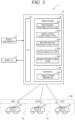
- FIG. 1 is a conceptual diagram showing an overview of a work zone boundary demarcation apparatus of an autonomously navigating work machine according to a first embodiment of this invention
- FIG. 2 is an explanatory side view of the autonomously navigating work machine of FIG. 1
- FIG. 3 is an explanatory diagram detailing configuration of a computer of FIG. 1
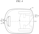
- FIG. 4 is a top view of the autonomously navigating work machine of FIG. 2
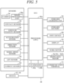
- FIG. 5 is a block diagram showing input-output relationships of an ECU (Electronic Control Unit) of the autonomously navigating work machine of FIG. 2
- FIG. 6 is an explanatory diagram of a work area to be serviced by the autonomously navigating work machine of FIG. 1 .
- Reference numeral 1 in FIG. 1 designates a work zone boundary demarcation apparatus of an autonomously navigating work machine (hereinafter called “apparatus”).
- the autonomously navigating work machine (hereinafter called “work machine 10") is a lawnmower, like that best shown in FIG. 2 .
- a single work machine 10 suffices, this embodiment assumes use of multiple work machines (e.g., three machines, as shown in FIG. 1 ), each of which is assigned to service its own work area AR.
- the apparatus 1 is equipped with a computer 2.
- the computer 2 comprises a processor (CPU) 2a, a memory 2b and an input/output circuit (I/O) 2c, which are interconnected through a bus.
- a display 4, and a keyboard, mouse, touch panel and other input equipment 6 are connected to the computer 2.
- a simulation program 2b1 for simulating work of at least one work machine 10 in the work area AR is loaded in the memory 2b of the computer 2.
- the simulation program 2b 1 is an interactive program that allows a user or other operator to perform simulation in accordance with conditions inputted through the input equipment 6 and that displays the results on the display 4.
- a body (base member) 12 of the work machine 10 comprises a chassis 12a and a frame 12b attached to the chassis 12a.
- the work machine 10 is equipped with two (left and right) front wheels 14 of relatively small diameter fixed through stays 12a1 to longitudinal (fore-aft) front end of the chassis 12a and with left and right rear wheels 16 of relatively large diameter directly attached to rear end of the chassis 12a.
- a lawn mower work blade (work unit; hereinafter sometimes called “blade”) 20 is attached to the chassis 12a near the middle thereof and an electric motor (hereinafter called “work motor”) 22 is installed above it.
- the blade 20 is connected to the work motor 22 and driven to rotate thereby.
- a blade height regulation mechanism 24 manually operable by a user is connected to the blade 20. (Blade height can optionally be power regulated rather than manually.)
- propulsion motors 26L and 26R are attached to the chassis 12a rearward of the blade 20.
- the propulsion motors 26L and 26R are connected to the left and right rear wheels 16 and rotate the rear wheels 16 normally or reversely independently on the left and right.
- the work machine 10 is of such weight and size as to be portable by the user.
- the work machine 10 has a total length (fore-aft length) of about 71 cm, total width of about 55 cm, and height of about 30 cm.
- An onboard charging unit 30 and an onboard battery 32 connected thereto are housed at the rear of the work machine 10, and two battery charging terminals 34 are attached to the frame 12b so as to project forward in running direction.
- the work motor 22 and propulsion motors 26 are connected to the onboard battery 32 and are powered thereby.
- Related wiring is not illustrated (is omitted) in FIG. 1 .
- Two cameras (photographic equipment) 36 are installed on the front end of the work machine 10 to enable forward or stereographic (360°) observation.
- a contact sensor 40 attached to the frame 12b outputs an ON signal when the frame 12b detaches from the chassis 12a upon striking against an obstacle or foreign body.
- a housing box (not shown) installed near the middle of the work machine 10 houses a printed circuit board 42 carrying an electronic control unit (hereinafter sometimes called "ECU") 44.
- the ECU 44 comprises a microcomputer equipped with at least a CPU (processor) 44a, memory (ROM, EEPROM and RAM) 44b and I/O (input/output circuit) 44c.
- the printed circuit board 42 is further provided thereon, in the vicinity of the ECU 44, with an angular velocity sensor 46 that generates an output indicating angular velocity (yaw rate) around a center-of-gravity z-axis (gravity axis) of the work machine 10, an acceleration sensor 50 that generates an output indicating acceleration acting on the work machine 10 in orthogonal three-axis (x, y and z) directions, and a direction sensor 52 that generates an output indicating absolute orientation in response to terrestrial magnetism.
- angular velocity sensor 46 that generates an output indicating angular velocity (yaw rate) around a center-of-gravity z-axis (gravity axis) of the work machine 10
- an acceleration sensor 50 that generates an output indicating acceleration acting on the work machine 10 in orthogonal three-axis (x, y and z) directions
- a direction sensor 52 that generates an output indicating absolute orientation in response to terrestrial magnetism.
- Wheel speed sensors 54 installed near the left and right rear wheels 16 of the work machine 10 generate outputs indicating wheel speeds of the left and right rear wheels 16, and a lift sensor 56 installed between the chassis 12a and the frame 12b outputs an ON signal when the frame 12b is lifted (raised) off the chassis 12a by someone such as the user.
- a current sensor 60 installed on the onboard battery 32 generates an output indicating consumption of onboard battery 32 current.
- the work machine 10 is equipped with a main switch 62 for instructing start of work operation and the like and an emergency stop switch 64 for instructing emergency stop, both of which are operable by the user.
- the frame 12b of the work machine 10 has a large cutaway in its upper surface, in which a keyboard, touch panel or other input device 66 is installed for input of instructions and the like by the user, and a display 70 is also installed.
- the input device 66 and the display 70 are connected to the ECU 44, and the display 70 displays working modes and other various information in accordance with commands from the ECU 44.
- the ECU 44 is configured to communicate through the I/O 44c with the computer 2 of the apparatus 1, by wire or wirelessly, by means of a communication terminal 72, as shown in FIG. 3 .
- the communication terminal 72 is a smartphone or other such PDA (Portable Digital Assistant) with communication function.
- outputs of the cameras 36, contact sensor 40, angular velocity sensor 46 and other sensors and outputs of the main switch 62 and other switches are sent to the ECU 44 and inputted through the I/O 44c.
- Outputs of the cameras 36 are similarly sent to an ECU-equipped image processing unit 36a, in which captured images are generated.
- FIG. 6 is an explanatory bird's eye view of a work area AR.
- the work area AR can be divided into multiple zones ARn (e.g., AR1, AR2 and AR3) demarked by boundaries (boundary lines) 74.
- a charging station (hereinafter called charging ST) 76 for charging the onboard battery 32 of the work machine 10 is installed in the working area AR.
- the work area AR which for simplification of illustration is shown only partially in the drawing, is defined in its entirety in the memory 2b by a map MP that has its origin at the position of the charging ST 76 and is formed by arraying multiple cells Cmp in a biaxial orthogonal coordinate system (XY plane) of uniformly spaced horizontal and perpendicular lines referenced with respect to direction determined by the direction sensor 52.
- a map MP that has its origin at the position of the charging ST 76 and is formed by arraying multiple cells Cmp in a biaxial orthogonal coordinate system (XY plane) of uniformly spaced horizontal and perpendicular lines referenced with respect to direction determined by the direction sensor 52.
- markers formed like, for example, triangular blocks are placed at appropriate intervals along the perimeter and the boundaries 74, and the ECU 44 recognizes the full work area AR by detecting the markers from captured images generated by the image processing unit 36a.
- the ECU 44 supplies power of the onboard battery 32 to the propulsion motors 26 based on the other sensor outputs and outputs control values through the I/O 44c so as to run the propulsion motors 26 and control the work machine 10 to perform lawn mowing as it autonomously navigates in the work area AR.
- the processor 2a in the computer 2 performs as a boundary demarcation unit 2a1 that demarcates the boundaries 74 which divide the work area AR into multiple zones ARn, a simulation execution unit 2a2 that executes simulation of work performed by three work machines 10 in multiple zones ARn divided by boundaries 74 demarcated by the boundary demarcation unit 2a1, a boundary re-demarcation unit 2a3 that re-demarcates boundaries demarcated by the boundary demarcation unit 2a1 based on results of simulation executed by the simulation execution unit 2a2, a zone display unit 2a4 that displays multiple zones ARn of the work area AR divided in accordance with boundaries re-demarcated by the boundary re-demarcation unit 2a3, and a work instruction unit 2a5 that instructs at least one work machine 10 to perform work in multiple zones ARn of the work area AR divided in accordance with boundaries re-demarcated by the boundary re-demarcation unit 2a3.
- a boundary demarcation unit 2a1 that demarcates the boundaries 74 which
- the number of work machines 10 and the number of zones ARn are both defined as three in this embodiment, but, needless to say, neither the number of work machines 10 nor the number of work region zones ARn is limited to three.
- a single work machine 10 can sequentially service multiple zones ARn at staggered times.
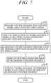
- FIG. 7 is a flowchart concretely indicating processing performed by the processor 2a of the computer 2 of the work area zone boundary demarcation apparatus 1.
- boundaries 74 that divide the work area AR into multiple zones ARn are demarcated (processing performed by the boundary demarcation unit 2a1).
- the boundary demarcation unit 2a1 first tentatively demarcated the boundaries 74. For example, as shown in FIG. 6 , the boundary demarcation unit 2a1 randomly demarcates two points a and b on the perimeter of the work area AR, whose positions can be set by proximity to some point or be set to make area fraction of the respective zones equal.
- the boundary demarcation unit 2a1 demarcates the boundaries 74 so as to minimize intersections between the boundaries 74.
- the boundary demarcation unit 2a1 demarcates the boundaries 74 so as to minimize intersections between the boundaries 74.
- the boundary 74 can be defined by any among a number of straight line segments, efficiency is improved by defining the boundary74 using the longest straight line segment.
- the work area AR often includes a narrow path 80 of constricted passage width for the work machine 10, but the boundary demarcation unit 2a1 is configured to demarcate the boundaries 74 so as to minimize area of the narrow path 80 (i.e., number of the narrow paths 80 if plural).
- the narrow path 80 is by definition a passageway of width w not less than n times greater than and less than m times greater than lateral width of the work machine 10 (left-right direction width perpendicular to fore-aft center line CL1 of body in FIG. 3 ).
- the boundary demarcation unit 2a1 is configured to demarcate the boundaries 74 so as to minimize area or number of such narrow paths 80.
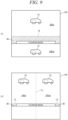
- FIG. 9 is a set of diagrams (i) and (ii) for explaining change of narrow path 80 area by boundary74 in the diagrams, an example is illustrated in which area of narrow path 80 is greater in (i) than in (ii). As area of the narrow path 80 is desirably made as small as possible, (ii) is preferable in the case shown in FIG. 9 .
- ARn and Arm are two among AR1, AR2 and AR3 of FIGs. 6 and 8 .
- the boundary demarcation unit 2a1 ascertains the positions of flower beds, trees, ponds and other unserviceable regions 82 in the work area AR from the cells Cmp of the map MP in response to input from the user or other operator and demarcates the boundaries 74 taking the ascertained unserviceable regions 82 into account.
- the boundary demarcation unit 2a1 is configured to update data regarding the work area AR at predetermined intervals such as every half year. Specifically, the boundary demarcation unit 2a1 determines at predetermined time intervals whether information including data regarding changes to the shape of the work area AR owing to construction, sale or other cause was inputted by the user, for example, and responds to such data having been inputted by updating the information regarding the work area AR.
- simulation of work performed by at least one work machine 10 in the three zones ARn divided by the demarcated boundaries 74 is executed (processing performed by the simulation execution unit 2a2).
- the simulation execution unit 2a2 performs simulation of work of at least one work machine 10 in the three zones ARn divided by the boundaries 74 demarcated by the boundary demarcation unit 2a1 in S10, it displays work time of the at least one work machine 10 on the display 4.
- the simulation execution unit 2a2 executes simulation of work of at least one work machine 10 in the three zones ARn divided by the boundaries 74 demarcated by the boundary demarcation unit 2a1 in S10, it also includes in the simulation travel time of the at least one work machine 10 between starting from a predetermined position (start point, e.g., charging ST 76) and arriving at its assigned zone ARn.
- start point e.g., charging ST 76
- the simulation execution unit 2a2 again executes simulation of work of at least one working machine 10 in the multiple zones ARn divided by the boundaries 74 demarcated based on the updated data.
- the boundaries 74 demarcated by the boundary demarcation unit 2a1 in S10 are re-demarcated based on results of the simulation executed by the simulation execution unit (step) 2a2 in S12 (processing performed by the boundary re-demarcation unit 2a3).
- the boundary re-demarcation unit 2a3 re-demarcates the boundaries 74 demarcated by the boundary demarcation unit 2a1 and the simulation execution unit 2a2 again executes simulation of work of at least one work machine 10 in the multiple zones ARn divided by the re-demarcated boundaries 74.
- the simulation execution unit 2a2 thus re-executes simulation of work of at least one working machine 10 in the three zones ARn divided by the boundaries 74 re-demarcated by the boundary re-demarcation unit 2a3.
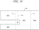
- the boundary re-demarcation unit 2a3 re-demarcates the boundaries demarcated by the boundary demarcation unit 2a1 so that the unserviced region comes to be included in an adjacent region and the simulation execution unit 2a2 again executes simulation of work of at least one work machine 10 in the multiple zones ARn divided by the re boundaries 74.
- a boundary 740 terminating ahead of the narrow path 80 is newly in place of the boundary 74 so that the unserviced region AR4 comes to be included in the work zone AR2 and simulation is executed in the new zone composed of AR4 + AR2 created by the newly demarcated boundary 740.
- At least one work machine 10 is prompted by an instruction to its ECU 44 to perform work in the multiple zones divided by the boundaries re-demarcated by the boundary re-demarcation unit 2a3 (work prompted by the work instruction unit 2a5).
- the zone boundary demarcation apparatus 1 of the work machine 10 can achieve improved efficiency when at least one work machine 10 performs work in a work area AR divided or demarcated into multiple zones ARn.
- FIG. 11 is a block diagram similar to FIG. 5 showing a work zone boundary demarcation apparatus of an autonomously navigating work machine according to a second embodiment of this invention and indicating input-output relationships of the ECU 44 of the work machine 10.
- At least one work machine 10 driven by propulsion motors 26 to be capable of autonomously navigating a work area AR comprises an ECU 44 constituted as a computer incorporating at least a processor 44a, a memory 44b and an input-output circuit 44c, and, similarly to what was explained with reference to FIG. 3 regarding the first embodiment, the memory 44b is loaded with a simulation program 44b1, similar to the simulation program 2b1, for simulating work of at least one work machine 10 in a work area.
- the processor 44a is configured to perform as a boundary demarcation unit 44a1, simulation execution unit 44a2, boundary re-demarcation unit 44a3, zone display unit 44a4 and work instruction unit 44a5 respectively similar to the boundary demarcation unit 2a1, simulation execution unit 2a2, boundary re-demarcation unit 2a3, zone display unit 2a4 and work instruction unit 2a5 of FIG. 3 .
- the work zone boundary demarcation apparatus 1 of the autonomously navigating work machine 10 is configured as described in the foregoing, it can, like the apparatus 1 of the first embodiment, achieve improved efficiency when at least one work machine 10 works in the work area AR divided into multiple zones ARn, and while its accuracy of simulation is slightly inferior to that of the first embodiment, it is advantageous for its simpler structure. Its other features and effects are no different from those of the first embodiment.
- the first and second embodiments of this invention is configured to have a work zone boundary demarcation apparatus (1) to demarcate boundaries (74) that divide a work area (AR) to be serviced by at least one autonomously navigating work machine (10) into multiple zones (ARn), comprising a computer (2, 44) having at least a processor (2a, 44a), a memory (2b, 44b), an input-output circuit (2c, 44c) and a simulation program (2b1, 44b1) loaded in the memory to simulate work of the work machine (10) in the work area, wherein the processor (2a,44a) is configured to perform as a boundary demarcation unit (2a1, 44a1, S10) that demarcates boundaries which divide the work area into multiple zones, a simulation execution unit (2a2, 44a2, S12) that executes simulation of work of the work machine in the multiple zones divided by the boundaries demarcated by the boundary demarcation unit, a boundary re-demarcation unit (2a3, 44a3, S14) that re-demarcates boundaries
- work times of the work machine 10 in the multiple zones ARn can be equalized by, for example, instructing the work machine 10 based on the display, so that efficiency when performing work by at least one work machine 10 can be improved by dividing a large work area AR into multiple zones ARn.
- the assumption in this context is that in the case of a single work machine 10, the multiple zones ARn are sequentially serviced at staggered times, and in the case of multiple work machines 10, each of the multiple zones is serviced by one of them.
- these embodiments are explained for the case of servicing each of multiple zones ARn with a single work machine 10, the embodiment is not limited to this mode and it is alternatively possible to service individual zones with multiple working machines 10.
- the apparatus includes a work instruction unit (2a5, 44a5, S18) that instructs the work machine(s) (10) to perform work in the multiple zones divided by the boundaries re-demarcated by the boundary re-demarcation unit.
- a work instruction unit (2a5, 44a5, S18) that instructs the work machine(s) (10) to perform work in the multiple zones divided by the boundaries re-demarcated by the boundary re-demarcation unit.
- the simulation execution unit (2a2, 44a2) re-executes simulation of work of the work machine in the multiple zones divided by the boundaries re-demarcated by the boundary re-demarcation unit (S12).
- the boundaries can be re-demarcated again based on the simulation results to more accurately equalize work times and still more thoroughly improve efficiency when dividing and servicing a large work area AR.
- the boundary re-demarcation unit (2a3, 44a3) re-demarcates the boundaries demarcated by the boundary demarcation unit and the simulation execution unit re-executes simulation of work of the work machine in the multiple zones divided by the re-demarcated boundaries (S14, S10).
- the boundary demarcation unit (2a1, 44a1) ascertains an unserviceable region(s) (82) in the work area (AR) and demarcates boundaries that divide the work area into multiple zones taking the ascertained unserviceable region(s) (82) into account (S14).
- the boundary demarcation unit (2a1, 44a1) ascertains an unserviceable region(s) (82) in the work area (AR) and demarcates boundaries that divide the work area into multiple zones taking the ascertained unserviceable region(s) (82) into account (S14).
- the simulation execution unit (2a2, 44a2) re-executes simulation of work of the work machine in the multiple zones divided by the re-demarcated boundaries (S12).
- the boundary demarcation unit (2a1, 44a1) updates data regarding the work area at predetermined intervals, and after data regarding the work area is updated by the boundary demarcation unit, the simulation execution unit (2a2, 44a2) re-executes simulation of work of the work machine in the multiple zones divided by the boundaries demarcated based on the updated data (S12).
- the boundary demarcation unit (2a1, 44a1) updates data regarding the work area at predetermined intervals
- the simulation execution unit (2a2, 44a2) re-executes simulation of work of the work machine in the multiple zones divided by the boundaries demarcated based on the updated data (S12).
- the boundary re-demarcation unit (2a3, 44a3) re-demarcates the boundaries demarcated by the boundary demarcation unit so as to include the unserviced region (AR4) in an area (AR2) adjacent to the unserviced region (AR4) and the simulation execution unit re-executes simulation of work of the work machine in the multiple zones divided by the re-demarcated boundaries (S14, S12).
- the apparatus includes a display (4, 70) connected to the computer and the boundary demarcation unit (2a1, 44a1) displays the demarcated boundaries on the display.
- the apparatus includes a display (4, 70) connected to the computer and the simulation execution unit (2a2, 44a2) displays work time of the work machine on the display at the time of executing simulation of work time of the work machine in the multiple zones divided by the boundaries demarcated by the boundary demarcation unit.
- the simulation execution unit (2a2, 44a2) when executing simulation of work of the work machine in the multiple zones divided by the boundaries demarcated by the boundary demarcation unit, includes in simulation travel time of the work machine up to arrival at the zone (S12). With this, work times can be more accurately equalized to still more thoroughly improve efficiency when dividing and servicing a large work area AR.
- the boundary demarcation unit (2a1, 44a1) demarcates the boundaries dividing the work area into multiple zones so as to minimize intersections between the boundaries (S10).
- the boundary demarcation unit (2a1, 44a1) demarcates the boundary dividing the work area into multiple zones using the longest line segment among the multiple line segments (S10).
- the boundary demarcation unit (2a1. 44a1) demarcates the boundaries dividing the work area into multiple zones so as to minimize area of a narrow path(s) (80) of the work area (S10).
- the first embodiment of this invention is configured such that the work machine (10) is equipped with a computer (ECU 44) comprising at least a processor (44a), memory (44b) and input/output circuit (44c), and the zone display unit (2a4) instructs the processor (44a) of the computer (ECU 44) of the work machine (10) via the input/output circuit (2c) to display the multiple zones divided based on boundaries re-demarcated by the boundary re-demarcation unit (S16).
- a computer ECU 44
- the zone display unit (2a4 instructs the processor (44a) of the computer (ECU 44) of the work machine (10) via the input/output circuit (2c) to display the multiple zones divided based on boundaries re-demarcated by the boundary re-demarcation unit (S16).
- the second embodiment of this invention is configured such that the work machine (10) is driven by drive units (electric motors 26) to be capable of autonomous navigation in the work area, and is equipped with a computer (ECU 44) comprising a processor (44a), memory (44b) and input/output circuit (44c), and wherein the memory (44b) is loaded with a simulation program (44b 1) that simulates work of the work machine in the work area and wherein the processor 44a is configured to perform as the boundary demarcation unit (44a1), simulation execution unit (44a2), boundary re-demarcation unit (44a3) and work instruction unit (44a4).
- a computer comprising a processor (44a), memory (44b) and input/output circuit (44c)
- the memory (44b) is loaded with a simulation program (44b 1) that simulates work of the work machine in the work area and wherein the processor 44a is configured to perform as the boundary demarcation unit (44a1), simulation execution unit (44a2), boundary re-demarc
- the work machine 10 is applied as a lawn mowing machine in the foregoing description, this invention is not limited to this application but can also be applied to any of various other kinds of autonomously navigating work units.
- the work zone boundary demarcation apparatus of autonomously navigating work machine according to this invention can be used suitably in simulation related to autonomously navigating work machines.
Claims (11)
- Arbeitszonengrenze-Demarkationsvorrichtung (1) zum Demarkieren von Grenzen (74), die einen von zumindest einer autonom navigierenden Arbeitsmaschine (10) zu bedienenden Arbeitsbereich (AR) in mehrere Zonen (ARn) unterteilen, umfassend:einen Computer (2, 44) mit zumindest einem Prozessor (2a, 44a), einem Speicher (2b, 44b), einer Eingabe-Ausgabe-Schaltung (2c, 44c) und einem in dem Speicher geladenen Simulationsprogramm (2b1, 44b1), um Arbeit der Arbeitsmaschine (10) in dem Arbeitsbereich (AR) zu simulieren;wobei der Prozessor konfiguriert ist zum Wirken als:eine Grenze-Demarkationseinheit (2a1, 44a1), die Grenzen (74), die den Arbeitsbereich in mehrere Zonen unterteilen, demarkiert,eine Simulationsausführungseinheit (2a2, 44a2), die eine Simulation der Arbeit der Arbeitsmaschine in den mehreren Zonen, die durch die von der Grenze-Demarkationseinheit demarkierten Grenzen (74) unterteilt sind, ausführt,eine Grenze-Redemarkationseinheit (2a3, 44a3), die von der Grenze-Demarkationseinheit demarkierte Grenzen basierend auf Ergebnissen der von der Simulationsausführungseinheit ausgeführten Simulation redemarkiert,eine Arbeitsanweisungseinheit (2a5, 44a5), die die Arbeitsmaschine (10) anweist, um Arbeit in den mehreren Zonen auszuführen, die durch die von der Grenze-Redemarkationseinheit redemarkierten Grenzen unterteilt sind, undeine Zonenanzeigeeinheit (2a4, 44a4), die die mehreren Zonen, die durch die von der Grenze-Redemarkationseinheit redemarkierten Grenzen unterteilt sind, anzeigt,wobei, wenn aus den Ergebnissen der von der Simulationsausführungseinheit ausgeführten Simulation bestimmt wird, dass in einer der mehreren Zonen eine nicht bediente Region (AR4) verbleibt, die Grenze-Redemarkationseinheit (2a3, 44a3) die von der Grenze-Demarkationseinheit demarkierten Grenzen redemarkiert, sodass sie die nicht bediente Region (AR4) in einem der nicht bedienten Region (AR4) benachbarten Bereich (AR2) enthalten, und die Simulationsausführungseinheit die Simulation der Arbeit der Arbeitsmaschine (10) in den mehreren Regionen, die durch die redemarkierten Grenzen unterteilt sind, erneut ausführt, undwobei, wenn aus den Ergebnissen der von der Simulationsausführungseinheit (2a2, 44a4) ausgeführten Simulation bestimmt wird, dass Arbeitslasten der mehreren Zonen, die durch die von der Grenze-Demarkationseinheit (2a1, 44a1) demarkierten Grenzen unterteilt sind, nicht gleich sind, die Grenze-Redemarkationseinheit die von der Grenze-Demarkationseinheit demarkierten Grenzen (74) redemarkiert und die Simulationsausführungseinheit die Simulation der Arbeit der Arbeitsmaschine in den mehreren Zonen, die durch die redemarkierten Grenzen unterteilt sind, erneut ausführt.
- Die Vorrichtung nach Anspruch 1, wobei die Simulationsausführungseinheit (2a2, 44a2) die Simulation der Arbeit der Arbeitsmaschine in den mehreren Zonen wieder ausführt, die durch die von der Grenze-Redemarkationseinheit wieder begrenzten Grenzen unterteilt sind.
- Die Vorrichtung nach Anspruch 1 oder 2, wobei die Grenze-Demarkationseinheit (2a1, 44a1) Daten in Bezug auf den Arbeitsbereich zu vorbestimmten Intervallen aktualisiert, und nachdem Daten in Bezug auf den Arbeitsbereich durch die Grenze-Demarkationseinheit aktualisiert sind, die Simulationsausführungseinheit (2a2, 44a4) die Simulation der Arbeit der Arbeitsmaschine (10) in den mehreren Zonen, die durch die basierend auf den aktualisierten Daten demarkierten Grenzen unterteilt sind, erneut ausführt.
- Die Vorrichtung nach einem der Ansprüche 1 bis 3, die ferner enthält:
eine Anzeige (4, 70), die mit dem Computer verbunden ist, und die Grenze-Demarkationseinheit (2a1, 44a1) die demarkierten Grenzen auf der Anzeige anzeigt. - Die Vorrichtung nach einem der Ansprüche 1 bis 4, die ferner enthält:eine Anzeige (4, 70), die mit dem Computer verbunden ist; unddie Simulationsausführungseinheit (2a2, 44a2) auf der Anzeige Arbeitszeit der Arbeitsmaschine zu der Zeit der Ausführung der Simulation der Arbeitszeit der Arbeitsmaschine in den mehreren Zonen, die durch die von der Grenze-Demarkationseinheit demarkierten Grenzen unterteilt sind, anzeigt.
- Die Vorrichtung nach einem der Ansprüche 1 bis 5, wobei, wenn die Simulation der Arbeit der Arbeitsmaschine (10) in den mehreren Zonen, die durch die von der Grenze-Demarkationseinheit demarkierten Grenzen (74) unterteilt sind, ausgeführt wird, die Simulationsausführungseinheit (2a2, 44a2) die Simulation der Fahrzeit der Arbeitsmaschine bis zur Ankunft an der Zone enthält.
- Die Vorrichtung nach einem der Ansprüche 1 bis 6, wobei die Grenze-Demarkationseinheit (2a1, 44a1) die Grenzen demarkiert, indem sie den Arbeitsbereich in mehrere Zonen unterteilt, um Überschneidungen zwischen den Grenzen (74) zu minimieren.
- Die Vorrichtung nach einem der Ansprüche 1 bis 7, wobei, wenn die Grenze unter einer beliebigen einer Anzahl gerader Liniensegmente (c, d) definiert werden kann, die Grenze-Demarkationseinheit (2a1, 44a1) die Grenze, die den Arbeitsbereich (AR) in mehrere Zonen unterteilt, mittels des längsten Liniensegments unter den mehreren Liniensegmenten demarkiert.
- Die Vorrichtung nach einem der Ansprüche 1 bis 8, wobei die Grenze-Demarkationseinheit (2a1, 44a1) die Grenze, die den Arbeitsbereich (AR) in mehrere Zonen unterteilt, demarkiert, um die Fläche eines schmalsten Wegs des Arbeitsbereiches zu minimieren.
- Die Vorrichtung nach einem der Ansprüche 1 bis 9, wobei die Arbeitsmaschine (10) mit einem Computer (44) ausgestattet ist, der zumindest einen Prozessor (44a), einen Speicher (44b) und eine Eingabe-Ausgabe-Schaltung (44c) aufweist, und die Zonenanzeigeeinheit (2a4) den Prozessor (44a) des Computers (44) der Arbeitsmaschine (10) über die Eingabe-Ausgabe-Schaltung (2c) anweist, die mehreren Zonen, die basierend auf den von der Grenze-Redemarkationseinheit redemarkierten Grenzen unterteilt sind, anzuzeigen.
- Die Vorrichtung nach einem der Ansprüche 1 bis 10, wobei die Arbeitsmaschine (10) von Antriebseinheiten (26) angetrieben ist, um in der Lage zu sein, in dem Arbeitsbereich autonom zu navigieren, und mit einem Computer (44) ausgestattet ist, der einen Prozessor (44a), einen Speicher (44b) und eine Eingabe-Ausgabe-Schaltung aufweist, und wobei der Speicher (44b) mit einem Simulationsprogramm (44b1) beladen ist, das die Arbeit der Arbeitsmaschine in dem Arbeitsbereich simuliert, und wobei der Prozessor (44a) konfiguriert ist, um, als die Grenze-Demarkationseinheit (44a1), die Simulationsausführungseinheit (44a2), die Grenze-Redemarkationseinheit (44a3) und die Arbeitsanweisungseinheit (44a5) zu wirken.
Applications Claiming Priority (1)
| Application Number | Priority Date | Filing Date | Title |
|---|---|---|---|
| PCT/JP2018/041305 WO2020095375A1 (ja) | 2018-11-07 | 2018-11-07 | 自律走行作業機の作業領域ゾーン境界画定装置 |
Publications (3)
| Publication Number | Publication Date |
|---|---|
| EP3879372A1 EP3879372A1 (de) | 2021-09-15 |
| EP3879372A4 EP3879372A4 (de) | 2021-09-22 |
| EP3879372B1 true EP3879372B1 (de) | 2023-06-28 |
Family
ID=70610842
Family Applications (1)
| Application Number | Title | Priority Date | Filing Date |
|---|---|---|---|
| EP18939638.5A Active EP3879372B1 (de) | 2018-11-07 | 2018-11-07 | Arbeitsbereichszonenabgrenzungsvorrichtung für autonome mobile arbeitsmaschine |
Country Status (4)
| Country | Link |
|---|---|
| US (1) | US20210397765A1 (de) |
| EP (1) | EP3879372B1 (de) |
| JP (1) | JP7116799B2 (de) |
| WO (1) | WO2020095375A1 (de) |
Families Citing this family (3)
| Publication number | Priority date | Publication date | Assignee | Title |
|---|---|---|---|---|
| SE546034C2 (en) * | 2021-12-23 | 2024-04-23 | Husqvarna Ab | Improved navigation for a robotic work tool system |
| SE546035C2 (en) * | 2021-12-23 | 2024-04-23 | Husqvarna Ab | Improved navigation for a robotic work tool system |
| US20240111299A1 (en) | 2022-09-29 | 2024-04-04 | Honda Motor Co., Ltd. | Work management device and work management method |
Family Cites Families (15)
| Publication number | Priority date | Publication date | Assignee | Title |
|---|---|---|---|---|
| US5321614A (en) * | 1991-06-06 | 1994-06-14 | Ashworth Guy T D | Navigational control apparatus and method for autonomus vehicles |
| JP2004139266A (ja) * | 2002-10-16 | 2004-05-13 | Toshiba Tec Corp | 自律走行ロボット |
| US6934615B2 (en) * | 2003-03-31 | 2005-08-23 | Deere & Company | Method and system for determining an efficient vehicle path |
| JP4264009B2 (ja) * | 2004-01-23 | 2009-05-13 | シャープ株式会社 | 自走式掃除機 |
| KR100791386B1 (ko) * | 2006-08-18 | 2008-01-07 | 삼성전자주식회사 | 이동 로봇의 영역 분리 방법 및 장치 |
| JP4999965B2 (ja) * | 2010-06-04 | 2012-08-15 | 中国電力株式会社 | 自動耕作方法、及び自動耕作システム |
| EP2703925B1 (de) | 2011-04-28 | 2021-02-24 | Positec Power Tools (Suzhou) Co., Ltd | Automatisches arbeitssystem, automatische gehvorrichtung und lenkverfahren dafür |
| JP2013228821A (ja) * | 2012-04-24 | 2013-11-07 | Mamiya-Op Nequos Co Ltd | 作業機械及びその構成装置、コンピュータプログラム |
| KR101372062B1 (ko) * | 2012-06-29 | 2014-03-07 | 인텔렉추얼디스커버리 주식회사 | 이동로봇 및 이동로봇의 온라인 전역경로 커버 제어방법 |
| JP5711301B2 (ja) * | 2013-05-29 | 2015-04-30 | シャープ株式会社 | サーバ、制御システム、自走式掃除機、制御方法、プログラム、および記録媒体 |
| KR102121554B1 (ko) * | 2014-07-30 | 2020-06-10 | 얀마 파워 테크놀로지 가부시키가이샤 | 원격 조작 장치 |
| JP5973608B1 (ja) * | 2015-03-27 | 2016-08-23 | 本田技研工業株式会社 | 無人作業車の制御装置 |
| DE112017000279T5 (de) * | 2016-03-30 | 2018-09-13 | Komatsu Ltd. | Simulationssystem und simulationsverfahren |
| EP3494769B1 (de) * | 2016-09-05 | 2022-11-02 | LG Electronics Inc. | Mobiler roboter und steuerungsverfahren dafür |
| WO2018108178A1 (zh) * | 2016-12-15 | 2018-06-21 | 苏州宝时得电动工具有限公司 | 自移动设备的回归方法、自移动设备、存储介质和服务器 |
-
2018
- 2018-11-07 US US17/287,677 patent/US20210397765A1/en active Pending
- 2018-11-07 EP EP18939638.5A patent/EP3879372B1/de active Active
- 2018-11-07 JP JP2020556396A patent/JP7116799B2/ja active Active
- 2018-11-07 WO PCT/JP2018/041305 patent/WO2020095375A1/ja unknown
Also Published As
| Publication number | Publication date |
|---|---|
| WO2020095375A1 (ja) | 2020-05-14 |
| JP7116799B2 (ja) | 2022-08-10 |
| JPWO2020095375A1 (ja) | 2021-09-24 |
| US20210397765A1 (en) | 2021-12-23 |
| EP3879372A4 (de) | 2021-09-22 |
| EP3879372A1 (de) | 2021-09-15 |
Similar Documents
| Publication | Publication Date | Title |
|---|---|---|
| EP3879372B1 (de) | Arbeitsbereichszonenabgrenzungsvorrichtung für autonome mobile arbeitsmaschine | |
| EP3073346B1 (de) | Steuerungsvorrichtung für autonom navigierendes nutzfahrzeug | |
| EP3073345B1 (de) | Steuerungsvorrichtung für autonom navigierendes nutzfahrzeug | |
| US10598505B2 (en) | Travel route generation apparatus and method for generating travel route | |
| EP3073344B1 (de) | Steuerungsvorrichtung für autonom navigierendes nutzfahrzeug | |
| EP3056960B1 (de) | Steuerungsvorrichtung für autonom navigierendes nutzfahrzeug | |
| JP6082415B2 (ja) | 車両の走行制御装置 | |
| JP6212590B2 (ja) | 自律走行作業車の制御装置 | |
| US9939812B2 (en) | Control apparatus for autonomously navigating utility vehicle | |
| JP2018073050A (ja) | 走行経路生成装置 | |
| EP3037907A1 (de) | Autonom unterstütztes und geführtes Fahrzeug | |
| JP2016186748A (ja) | 無人作業車の制御装置 | |
| EP3819738B1 (de) | Verfahren, vorrichtung und system zur steuerung der bewegung mehrerer fahrzeuge und computerlesbares speichermedium | |
| JP2018073008A (ja) | 走行経路生成装置 | |
| JP6884092B2 (ja) | 作業車及び作業車のための走行経路選択システム | |
| EP4049916A1 (de) | Fahrzeugsteuerungsverfahren, fahrzeugsteuerungssystem und fahrzeug | |
| JP7076195B2 (ja) | 作業車自動走行システム | |
| CN114872051B (zh) | 通行地图获取系统、方法、机器人及计算机可读存储介质 | |
| JP7016081B2 (ja) | 無人航空機の飛行計画経路を修正するためのシステム、方法、プログラム及びプログラムを記憶した記憶媒体 | |
| JP6962559B2 (ja) | 移動体制御装置 | |
| CN115464620A (zh) | 设备维护的方法、装置、运维系统和运维机器人 | |
| WO2023205244A1 (en) | Path planning for automatic mowers | |
| Kumar | Development of an automatic guided vehicle with an obstacle avoidance system | |
| CN115390577A (zh) | 一种拒止环境下无人机的自主导航与控制方法 | |
| JPWO2020110248A1 (ja) | 作業機、作業機の制御方法及びプログラム |
Legal Events
| Date | Code | Title | Description |
|---|---|---|---|
| STAA | Information on the status of an ep patent application or granted ep patent |
Free format text: STATUS: THE INTERNATIONAL PUBLICATION HAS BEEN MADE |
|
| PUAI | Public reference made under article 153(3) epc to a published international application that has entered the european phase |
Free format text: ORIGINAL CODE: 0009012 |
|
| STAA | Information on the status of an ep patent application or granted ep patent |
Free format text: STATUS: REQUEST FOR EXAMINATION WAS MADE |
|
| 17P | Request for examination filed |
Effective date: 20210504 |
|
| AK | Designated contracting states |
Kind code of ref document: A1 Designated state(s): AL AT BE BG CH CY CZ DE DK EE ES FI FR GB GR HR HU IE IS IT LI LT LU LV MC MK MT NL NO PL PT RO RS SE SI SK SM TR |
|
| A4 | Supplementary search report drawn up and despatched |
Effective date: 20210819 |
|
| RIC1 | Information provided on ipc code assigned before grant |
Ipc: G05D 1/00 20060101ALI20210813BHEP Ipc: G05D 1/02 20200101AFI20210813BHEP |
|
| DAV | Request for validation of the european patent (deleted) | ||
| DAX | Request for extension of the european patent (deleted) | ||
| STAA | Information on the status of an ep patent application or granted ep patent |
Free format text: STATUS: EXAMINATION IS IN PROGRESS |
|
| 17Q | First examination report despatched |
Effective date: 20220406 |
|
| GRAP | Despatch of communication of intention to grant a patent |
Free format text: ORIGINAL CODE: EPIDOSNIGR1 |
|
| STAA | Information on the status of an ep patent application or granted ep patent |
Free format text: STATUS: GRANT OF PATENT IS INTENDED |
|
| INTG | Intention to grant announced |
Effective date: 20230220 |
|
| GRAS | Grant fee paid |
Free format text: ORIGINAL CODE: EPIDOSNIGR3 |
|
| GRAA | (expected) grant |
Free format text: ORIGINAL CODE: 0009210 |
|
| STAA | Information on the status of an ep patent application or granted ep patent |
Free format text: STATUS: THE PATENT HAS BEEN GRANTED |
|
| AK | Designated contracting states |
Kind code of ref document: B1 Designated state(s): AL AT BE BG CH CY CZ DE DK EE ES FI FR GB GR HR HU IE IS IT LI LT LU LV MC MK MT NL NO PL PT RO RS SE SI SK SM TR |
|
| REG | Reference to a national code |
Ref country code: CH Ref legal event code: EP |
|
| REG | Reference to a national code |
Ref country code: AT Ref legal event code: REF Ref document number: 1583257 Country of ref document: AT Kind code of ref document: T Effective date: 20230715 |
|
| REG | Reference to a national code |
Ref country code: IE Ref legal event code: FG4D |
|
| REG | Reference to a national code |
Ref country code: DE Ref legal event code: R096 Ref document number: 602018052672 Country of ref document: DE |
|
| P01 | Opt-out of the competence of the unified patent court (upc) registered |
Effective date: 20230619 |
|
| REG | Reference to a national code |
Ref country code: LT Ref legal event code: MG9D |
|
| PG25 | Lapsed in a contracting state [announced via postgrant information from national office to epo] |
Ref country code: SE Free format text: LAPSE BECAUSE OF FAILURE TO SUBMIT A TRANSLATION OF THE DESCRIPTION OR TO PAY THE FEE WITHIN THE PRESCRIBED TIME-LIMIT Effective date: 20230628 Ref country code: NO Free format text: LAPSE BECAUSE OF FAILURE TO SUBMIT A TRANSLATION OF THE DESCRIPTION OR TO PAY THE FEE WITHIN THE PRESCRIBED TIME-LIMIT Effective date: 20230928 |
|
| REG | Reference to a national code |
Ref country code: NL Ref legal event code: MP Effective date: 20230628 |
|
| REG | Reference to a national code |
Ref country code: AT Ref legal event code: MK05 Ref document number: 1583257 Country of ref document: AT Kind code of ref document: T Effective date: 20230628 |
|
| REG | Reference to a national code |
Ref country code: DE Ref legal event code: R079 Ref document number: 602018052672 Country of ref document: DE Free format text: PREVIOUS MAIN CLASS: G05D0001020000 Ipc: G05D0001430000 |
|
| PG25 | Lapsed in a contracting state [announced via postgrant information from national office to epo] |
Ref country code: RS Free format text: LAPSE BECAUSE OF FAILURE TO SUBMIT A TRANSLATION OF THE DESCRIPTION OR TO PAY THE FEE WITHIN THE PRESCRIBED TIME-LIMIT Effective date: 20230628 Ref country code: NL Free format text: LAPSE BECAUSE OF FAILURE TO SUBMIT A TRANSLATION OF THE DESCRIPTION OR TO PAY THE FEE WITHIN THE PRESCRIBED TIME-LIMIT Effective date: 20230628 Ref country code: LV Free format text: LAPSE BECAUSE OF FAILURE TO SUBMIT A TRANSLATION OF THE DESCRIPTION OR TO PAY THE FEE WITHIN THE PRESCRIBED TIME-LIMIT Effective date: 20230628 Ref country code: LT Free format text: LAPSE BECAUSE OF FAILURE TO SUBMIT A TRANSLATION OF THE DESCRIPTION OR TO PAY THE FEE WITHIN THE PRESCRIBED TIME-LIMIT Effective date: 20230628 Ref country code: HR Free format text: LAPSE BECAUSE OF FAILURE TO SUBMIT A TRANSLATION OF THE DESCRIPTION OR TO PAY THE FEE WITHIN THE PRESCRIBED TIME-LIMIT Effective date: 20230628 Ref country code: GR Free format text: LAPSE BECAUSE OF FAILURE TO SUBMIT A TRANSLATION OF THE DESCRIPTION OR TO PAY THE FEE WITHIN THE PRESCRIBED TIME-LIMIT Effective date: 20230929 |
|
| PG25 | Lapsed in a contracting state [announced via postgrant information from national office to epo] |
Ref country code: FI Free format text: LAPSE BECAUSE OF FAILURE TO SUBMIT A TRANSLATION OF THE DESCRIPTION OR TO PAY THE FEE WITHIN THE PRESCRIBED TIME-LIMIT Effective date: 20230628 |
|
| PG25 | Lapsed in a contracting state [announced via postgrant information from national office to epo] |
Ref country code: SK Free format text: LAPSE BECAUSE OF FAILURE TO SUBMIT A TRANSLATION OF THE DESCRIPTION OR TO PAY THE FEE WITHIN THE PRESCRIBED TIME-LIMIT Effective date: 20230628 |
|
| PG25 | Lapsed in a contracting state [announced via postgrant information from national office to epo] |
Ref country code: ES Free format text: LAPSE BECAUSE OF FAILURE TO SUBMIT A TRANSLATION OF THE DESCRIPTION OR TO PAY THE FEE WITHIN THE PRESCRIBED TIME-LIMIT Effective date: 20230628 |
|
| PG25 | Lapsed in a contracting state [announced via postgrant information from national office to epo] |
Ref country code: IS Free format text: LAPSE BECAUSE OF FAILURE TO SUBMIT A TRANSLATION OF THE DESCRIPTION OR TO PAY THE FEE WITHIN THE PRESCRIBED TIME-LIMIT Effective date: 20231028 |
|
| PG25 | Lapsed in a contracting state [announced via postgrant information from national office to epo] |
Ref country code: SM Free format text: LAPSE BECAUSE OF FAILURE TO SUBMIT A TRANSLATION OF THE DESCRIPTION OR TO PAY THE FEE WITHIN THE PRESCRIBED TIME-LIMIT Effective date: 20230628 Ref country code: SK Free format text: LAPSE BECAUSE OF FAILURE TO SUBMIT A TRANSLATION OF THE DESCRIPTION OR TO PAY THE FEE WITHIN THE PRESCRIBED TIME-LIMIT Effective date: 20230628 Ref country code: RO Free format text: LAPSE BECAUSE OF FAILURE TO SUBMIT A TRANSLATION OF THE DESCRIPTION OR TO PAY THE FEE WITHIN THE PRESCRIBED TIME-LIMIT Effective date: 20230628 Ref country code: PT Free format text: LAPSE BECAUSE OF FAILURE TO SUBMIT A TRANSLATION OF THE DESCRIPTION OR TO PAY THE FEE WITHIN THE PRESCRIBED TIME-LIMIT Effective date: 20231030 Ref country code: IS Free format text: LAPSE BECAUSE OF FAILURE TO SUBMIT A TRANSLATION OF THE DESCRIPTION OR TO PAY THE FEE WITHIN THE PRESCRIBED TIME-LIMIT Effective date: 20231028 Ref country code: ES Free format text: LAPSE BECAUSE OF FAILURE TO SUBMIT A TRANSLATION OF THE DESCRIPTION OR TO PAY THE FEE WITHIN THE PRESCRIBED TIME-LIMIT Effective date: 20230628 Ref country code: EE Free format text: LAPSE BECAUSE OF FAILURE TO SUBMIT A TRANSLATION OF THE DESCRIPTION OR TO PAY THE FEE WITHIN THE PRESCRIBED TIME-LIMIT Effective date: 20230628 Ref country code: CZ Free format text: LAPSE BECAUSE OF FAILURE TO SUBMIT A TRANSLATION OF THE DESCRIPTION OR TO PAY THE FEE WITHIN THE PRESCRIBED TIME-LIMIT Effective date: 20230628 Ref country code: AT Free format text: LAPSE BECAUSE OF FAILURE TO SUBMIT A TRANSLATION OF THE DESCRIPTION OR TO PAY THE FEE WITHIN THE PRESCRIBED TIME-LIMIT Effective date: 20230628 |
|
| PGFP | Annual fee paid to national office [announced via postgrant information from national office to epo] |
Ref country code: FR Payment date: 20231120 Year of fee payment: 6 Ref country code: DE Payment date: 20231031 Year of fee payment: 6 |
|
| PG25 | Lapsed in a contracting state [announced via postgrant information from national office to epo] |
Ref country code: PL Free format text: LAPSE BECAUSE OF FAILURE TO SUBMIT A TRANSLATION OF THE DESCRIPTION OR TO PAY THE FEE WITHIN THE PRESCRIBED TIME-LIMIT Effective date: 20230628 |
|
| PG25 | Lapsed in a contracting state [announced via postgrant information from national office to epo] |
Ref country code: DK Free format text: LAPSE BECAUSE OF FAILURE TO SUBMIT A TRANSLATION OF THE DESCRIPTION OR TO PAY THE FEE WITHIN THE PRESCRIBED TIME-LIMIT Effective date: 20230628 |
|
| PLBE | No opposition filed within time limit |
Free format text: ORIGINAL CODE: 0009261 |
|
| STAA | Information on the status of an ep patent application or granted ep patent |
Free format text: STATUS: NO OPPOSITION FILED WITHIN TIME LIMIT |