EP3879307B1 - Verfahren und vorrichtung zur detektion eines hindernisses - Google Patents
Verfahren und vorrichtung zur detektion eines hindernisses Download PDFInfo
- Publication number
- EP3879307B1 EP3879307B1 EP20196156.2A EP20196156A EP3879307B1 EP 3879307 B1 EP3879307 B1 EP 3879307B1 EP 20196156 A EP20196156 A EP 20196156A EP 3879307 B1 EP3879307 B1 EP 3879307B1
- Authority
- EP
- European Patent Office
- Prior art keywords
- points
- position points
- projection points
- boundary line
- vehicle
- Prior art date
- Legal status (The legal status is an assumption and is not a legal conclusion. Google has not performed a legal analysis and makes no representation as to the accuracy of the status listed.)
- Active
Links
Images


Classifications
-
- B—PERFORMING OPERATIONS; TRANSPORTING
- B60—VEHICLES IN GENERAL
- B60W—CONJOINT CONTROL OF VEHICLE SUB-UNITS OF DIFFERENT TYPE OR DIFFERENT FUNCTION; CONTROL SYSTEMS SPECIALLY ADAPTED FOR HYBRID VEHICLES; ROAD VEHICLE DRIVE CONTROL SYSTEMS FOR PURPOSES NOT RELATED TO THE CONTROL OF A PARTICULAR SUB-UNIT
- B60W30/00—Purposes of road vehicle drive control systems not related to the control of a particular sub-unit, e.g. of systems using conjoint control of vehicle sub-units
- B60W30/08—Active safety systems predicting or avoiding probable or impending collision or attempting to minimise its consequences
-
- B—PERFORMING OPERATIONS; TRANSPORTING
- B60—VEHICLES IN GENERAL
- B60R—VEHICLES, VEHICLE FITTINGS, OR VEHICLE PARTS, NOT OTHERWISE PROVIDED FOR
- B60R16/00—Electric or fluid circuits specially adapted for vehicles and not otherwise provided for; Arrangement of elements of electric or fluid circuits specially adapted for vehicles and not otherwise provided for
- B60R16/02—Electric or fluid circuits specially adapted for vehicles and not otherwise provided for; Arrangement of elements of electric or fluid circuits specially adapted for vehicles and not otherwise provided for electric constitutive elements
- B60R16/023—Electric or fluid circuits specially adapted for vehicles and not otherwise provided for; Arrangement of elements of electric or fluid circuits specially adapted for vehicles and not otherwise provided for electric constitutive elements for transmission of signals between vehicle parts or subsystems
-
- B—PERFORMING OPERATIONS; TRANSPORTING
- B60—VEHICLES IN GENERAL
- B60R—VEHICLES, VEHICLE FITTINGS, OR VEHICLE PARTS, NOT OTHERWISE PROVIDED FOR
- B60R21/00—Arrangements or fittings on vehicles for protecting or preventing injuries to occupants or pedestrians in case of accidents or other traffic risks
- B60R21/01—Electrical circuits for triggering passive safety arrangements, e.g. airbags, safety belt tighteners, in case of vehicle accidents or impending vehicle accidents
- B60R21/013—Electrical circuits for triggering passive safety arrangements, e.g. airbags, safety belt tighteners, in case of vehicle accidents or impending vehicle accidents including means for detecting collisions, impending collisions or roll-over
- B60R21/0134—Electrical circuits for triggering passive safety arrangements, e.g. airbags, safety belt tighteners, in case of vehicle accidents or impending vehicle accidents including means for detecting collisions, impending collisions or roll-over responsive to imminent contact with an obstacle, e.g. using radar systems
-
- B—PERFORMING OPERATIONS; TRANSPORTING
- B60—VEHICLES IN GENERAL
- B60W—CONJOINT CONTROL OF VEHICLE SUB-UNITS OF DIFFERENT TYPE OR DIFFERENT FUNCTION; CONTROL SYSTEMS SPECIALLY ADAPTED FOR HYBRID VEHICLES; ROAD VEHICLE DRIVE CONTROL SYSTEMS FOR PURPOSES NOT RELATED TO THE CONTROL OF A PARTICULAR SUB-UNIT
- B60W40/00—Estimation or calculation of non-directly measurable driving parameters for road vehicle drive control systems not related to the control of a particular sub unit, e.g. by using mathematical models
- B60W40/02—Estimation or calculation of non-directly measurable driving parameters for road vehicle drive control systems not related to the control of a particular sub unit, e.g. by using mathematical models related to ambient conditions
-
- B—PERFORMING OPERATIONS; TRANSPORTING
- B60—VEHICLES IN GENERAL
- B60W—CONJOINT CONTROL OF VEHICLE SUB-UNITS OF DIFFERENT TYPE OR DIFFERENT FUNCTION; CONTROL SYSTEMS SPECIALLY ADAPTED FOR HYBRID VEHICLES; ROAD VEHICLE DRIVE CONTROL SYSTEMS FOR PURPOSES NOT RELATED TO THE CONTROL OF A PARTICULAR SUB-UNIT
- B60W60/00—Drive control systems specially adapted for autonomous road vehicles
- B60W60/001—Planning or execution of driving tasks
- B60W60/0015—Planning or execution of driving tasks specially adapted for safety
-
- G—PHYSICS
- G01—MEASURING; TESTING
- G01S—RADIO DIRECTION-FINDING; RADIO NAVIGATION; DETERMINING DISTANCE OR VELOCITY BY USE OF RADIO WAVES; LOCATING OR PRESENCE-DETECTING BY USE OF THE REFLECTION OR RERADIATION OF RADIO WAVES; ANALOGOUS ARRANGEMENTS USING OTHER WAVES
- G01S13/00—Systems using the reflection or reradiation of radio waves, e.g. radar systems; Analogous systems using reflection or reradiation of waves whose nature or wavelength is irrelevant or unspecified
- G01S13/86—Combinations of radar systems with non-radar systems, e.g. sonar, direction finder
- G01S13/867—Combination of radar systems with cameras
-
- G—PHYSICS
- G01—MEASURING; TESTING
- G01S—RADIO DIRECTION-FINDING; RADIO NAVIGATION; DETERMINING DISTANCE OR VELOCITY BY USE OF RADIO WAVES; LOCATING OR PRESENCE-DETECTING BY USE OF THE REFLECTION OR RERADIATION OF RADIO WAVES; ANALOGOUS ARRANGEMENTS USING OTHER WAVES
- G01S13/00—Systems using the reflection or reradiation of radio waves, e.g. radar systems; Analogous systems using reflection or reradiation of waves whose nature or wavelength is irrelevant or unspecified
- G01S13/88—Radar or analogous systems specially adapted for specific applications
- G01S13/93—Radar or analogous systems specially adapted for specific applications for anti-collision purposes
- G01S13/931—Radar or analogous systems specially adapted for specific applications for anti-collision purposes of land vehicles
-
- G—PHYSICS
- G01—MEASURING; TESTING
- G01S—RADIO DIRECTION-FINDING; RADIO NAVIGATION; DETERMINING DISTANCE OR VELOCITY BY USE OF RADIO WAVES; LOCATING OR PRESENCE-DETECTING BY USE OF THE REFLECTION OR RERADIATION OF RADIO WAVES; ANALOGOUS ARRANGEMENTS USING OTHER WAVES
- G01S7/00—Details of systems according to groups G01S13/00, G01S15/00, G01S17/00
- G01S7/02—Details of systems according to groups G01S13/00, G01S15/00, G01S17/00 of systems according to group G01S13/00
- G01S7/41—Details of systems according to groups G01S13/00, G01S15/00, G01S17/00 of systems according to group G01S13/00 using analysis of echo signal for target characterisation; Target signature; Target cross-section
- G01S7/411—Identification of targets based on measurements of radar reflectivity
- G01S7/412—Identification of targets based on measurements of radar reflectivity based on a comparison between measured values and known or stored values
-
- G—PHYSICS
- G01—MEASURING; TESTING
- G01S—RADIO DIRECTION-FINDING; RADIO NAVIGATION; DETERMINING DISTANCE OR VELOCITY BY USE OF RADIO WAVES; LOCATING OR PRESENCE-DETECTING BY USE OF THE REFLECTION OR RERADIATION OF RADIO WAVES; ANALOGOUS ARRANGEMENTS USING OTHER WAVES
- G01S7/00—Details of systems according to groups G01S13/00, G01S15/00, G01S17/00
- G01S7/02—Details of systems according to groups G01S13/00, G01S15/00, G01S17/00 of systems according to group G01S13/00
- G01S7/41—Details of systems according to groups G01S13/00, G01S15/00, G01S17/00 of systems according to group G01S13/00 using analysis of echo signal for target characterisation; Target signature; Target cross-section
- G01S7/417—Details of systems according to groups G01S13/00, G01S15/00, G01S17/00 of systems according to group G01S13/00 using analysis of echo signal for target characterisation; Target signature; Target cross-section involving the use of neural networks
-
- G—PHYSICS
- G01—MEASURING; TESTING
- G01S—RADIO DIRECTION-FINDING; RADIO NAVIGATION; DETERMINING DISTANCE OR VELOCITY BY USE OF RADIO WAVES; LOCATING OR PRESENCE-DETECTING BY USE OF THE REFLECTION OR RERADIATION OF RADIO WAVES; ANALOGOUS ARRANGEMENTS USING OTHER WAVES
- G01S7/00—Details of systems according to groups G01S13/00, G01S15/00, G01S17/00
- G01S7/02—Details of systems according to groups G01S13/00, G01S15/00, G01S17/00 of systems according to group G01S13/00
- G01S7/41—Details of systems according to groups G01S13/00, G01S15/00, G01S17/00 of systems according to group G01S13/00 using analysis of echo signal for target characterisation; Target signature; Target cross-section
- G01S7/418—Theoretical aspects
-
- G—PHYSICS
- G06—COMPUTING OR CALCULATING; COUNTING
- G06N—COMPUTING ARRANGEMENTS BASED ON SPECIFIC COMPUTATIONAL MODELS
- G06N3/00—Computing arrangements based on biological models
- G06N3/02—Neural networks
- G06N3/04—Architecture, e.g. interconnection topology
-
- G—PHYSICS
- G06—COMPUTING OR CALCULATING; COUNTING
- G06T—IMAGE DATA PROCESSING OR GENERATION, IN GENERAL
- G06T7/00—Image analysis
- G06T7/50—Depth or shape recovery
-
- G—PHYSICS
- G06—COMPUTING OR CALCULATING; COUNTING
- G06T—IMAGE DATA PROCESSING OR GENERATION, IN GENERAL
- G06T7/00—Image analysis
- G06T7/70—Determining position or orientation of objects or cameras
-
- G—PHYSICS
- G06—COMPUTING OR CALCULATING; COUNTING
- G06V—IMAGE OR VIDEO RECOGNITION OR UNDERSTANDING
- G06V10/00—Arrangements for image or video recognition or understanding
- G06V10/20—Image preprocessing
- G06V10/25—Determination of region of interest [ROI] or a volume of interest [VOI]
-
- G—PHYSICS
- G06—COMPUTING OR CALCULATING; COUNTING
- G06V—IMAGE OR VIDEO RECOGNITION OR UNDERSTANDING
- G06V20/00—Scenes; Scene-specific elements
- G06V20/50—Context or environment of the image
- G06V20/56—Context or environment of the image exterior to a vehicle by using sensors mounted on the vehicle
- G06V20/58—Recognition of moving objects or obstacles, e.g. vehicles or pedestrians; Recognition of traffic objects, e.g. traffic signs, traffic lights or roads
-
- G—PHYSICS
- G06—COMPUTING OR CALCULATING; COUNTING
- G06V—IMAGE OR VIDEO RECOGNITION OR UNDERSTANDING
- G06V20/00—Scenes; Scene-specific elements
- G06V20/50—Context or environment of the image
- G06V20/56—Context or environment of the image exterior to a vehicle by using sensors mounted on the vehicle
- G06V20/588—Recognition of the road, e.g. of lane markings; Recognition of the vehicle driving pattern in relation to the road
-
- H—ELECTRICITY
- H04—ELECTRIC COMMUNICATION TECHNIQUE
- H04N—PICTORIAL COMMUNICATION, e.g. TELEVISION
- H04N23/00—Cameras or camera modules comprising electronic image sensors; Control thereof
- H04N23/57—Mechanical or electrical details of cameras or camera modules specially adapted for being embedded in other devices
-
- B—PERFORMING OPERATIONS; TRANSPORTING
- B60—VEHICLES IN GENERAL
- B60W—CONJOINT CONTROL OF VEHICLE SUB-UNITS OF DIFFERENT TYPE OR DIFFERENT FUNCTION; CONTROL SYSTEMS SPECIALLY ADAPTED FOR HYBRID VEHICLES; ROAD VEHICLE DRIVE CONTROL SYSTEMS FOR PURPOSES NOT RELATED TO THE CONTROL OF A PARTICULAR SUB-UNIT
- B60W50/00—Details of control systems for road vehicle drive control not related to the control of a particular sub-unit, e.g. process diagnostic or vehicle driver interfaces
- B60W2050/0001—Details of the control system
- B60W2050/0002—Automatic control, details of type of controller or control system architecture
- B60W2050/0004—In digital systems, e.g. discrete-time systems involving sampling
- B60W2050/0005—Processor details or data handling, e.g. memory registers or chip architecture
-
- B—PERFORMING OPERATIONS; TRANSPORTING
- B60—VEHICLES IN GENERAL
- B60W—CONJOINT CONTROL OF VEHICLE SUB-UNITS OF DIFFERENT TYPE OR DIFFERENT FUNCTION; CONTROL SYSTEMS SPECIALLY ADAPTED FOR HYBRID VEHICLES; ROAD VEHICLE DRIVE CONTROL SYSTEMS FOR PURPOSES NOT RELATED TO THE CONTROL OF A PARTICULAR SUB-UNIT
- B60W50/00—Details of control systems for road vehicle drive control not related to the control of a particular sub-unit, e.g. process diagnostic or vehicle driver interfaces
- B60W2050/0001—Details of the control system
- B60W2050/0043—Signal treatments, identification of variables or parameters, parameter estimation or state estimation
- B60W2050/0052—Filtering, filters
-
- B—PERFORMING OPERATIONS; TRANSPORTING
- B60—VEHICLES IN GENERAL
- B60W—CONJOINT CONTROL OF VEHICLE SUB-UNITS OF DIFFERENT TYPE OR DIFFERENT FUNCTION; CONTROL SYSTEMS SPECIALLY ADAPTED FOR HYBRID VEHICLES; ROAD VEHICLE DRIVE CONTROL SYSTEMS FOR PURPOSES NOT RELATED TO THE CONTROL OF A PARTICULAR SUB-UNIT
- B60W2420/00—Indexing codes relating to the type of sensors based on the principle of their operation
- B60W2420/40—Photo, light or radio wave sensitive means, e.g. infrared sensors
- B60W2420/403—Image sensing, e.g. optical camera
-
- B—PERFORMING OPERATIONS; TRANSPORTING
- B60—VEHICLES IN GENERAL
- B60W—CONJOINT CONTROL OF VEHICLE SUB-UNITS OF DIFFERENT TYPE OR DIFFERENT FUNCTION; CONTROL SYSTEMS SPECIALLY ADAPTED FOR HYBRID VEHICLES; ROAD VEHICLE DRIVE CONTROL SYSTEMS FOR PURPOSES NOT RELATED TO THE CONTROL OF A PARTICULAR SUB-UNIT
- B60W2420/00—Indexing codes relating to the type of sensors based on the principle of their operation
- B60W2420/40—Photo, light or radio wave sensitive means, e.g. infrared sensors
- B60W2420/408—Radar; Laser, e.g. lidar
-
- B—PERFORMING OPERATIONS; TRANSPORTING
- B60—VEHICLES IN GENERAL
- B60W—CONJOINT CONTROL OF VEHICLE SUB-UNITS OF DIFFERENT TYPE OR DIFFERENT FUNCTION; CONTROL SYSTEMS SPECIALLY ADAPTED FOR HYBRID VEHICLES; ROAD VEHICLE DRIVE CONTROL SYSTEMS FOR PURPOSES NOT RELATED TO THE CONTROL OF A PARTICULAR SUB-UNIT
- B60W2552/00—Input parameters relating to infrastructure
- B60W2552/50—Barriers
-
- B—PERFORMING OPERATIONS; TRANSPORTING
- B60—VEHICLES IN GENERAL
- B60Y—INDEXING SCHEME RELATING TO ASPECTS CROSS-CUTTING VEHICLE TECHNOLOGY
- B60Y2300/00—Purposes or special features of road vehicle drive control systems
- B60Y2300/08—Predicting or avoiding probable or impending collision
-
- G—PHYSICS
- G01—MEASURING; TESTING
- G01S—RADIO DIRECTION-FINDING; RADIO NAVIGATION; DETERMINING DISTANCE OR VELOCITY BY USE OF RADIO WAVES; LOCATING OR PRESENCE-DETECTING BY USE OF THE REFLECTION OR RERADIATION OF RADIO WAVES; ANALOGOUS ARRANGEMENTS USING OTHER WAVES
- G01S13/00—Systems using the reflection or reradiation of radio waves, e.g. radar systems; Analogous systems using reflection or reradiation of waves whose nature or wavelength is irrelevant or unspecified
- G01S13/88—Radar or analogous systems specially adapted for specific applications
- G01S13/93—Radar or analogous systems specially adapted for specific applications for anti-collision purposes
- G01S13/931—Radar or analogous systems specially adapted for specific applications for anti-collision purposes of land vehicles
- G01S2013/9322—Radar or analogous systems specially adapted for specific applications for anti-collision purposes of land vehicles using additional data, e.g. driver condition, road state or weather data
-
- G—PHYSICS
- G01—MEASURING; TESTING
- G01S—RADIO DIRECTION-FINDING; RADIO NAVIGATION; DETERMINING DISTANCE OR VELOCITY BY USE OF RADIO WAVES; LOCATING OR PRESENCE-DETECTING BY USE OF THE REFLECTION OR RERADIATION OF RADIO WAVES; ANALOGOUS ARRANGEMENTS USING OTHER WAVES
- G01S13/00—Systems using the reflection or reradiation of radio waves, e.g. radar systems; Analogous systems using reflection or reradiation of waves whose nature or wavelength is irrelevant or unspecified
- G01S13/88—Radar or analogous systems specially adapted for specific applications
- G01S13/93—Radar or analogous systems specially adapted for specific applications for anti-collision purposes
- G01S13/931—Radar or analogous systems specially adapted for specific applications for anti-collision purposes of land vehicles
- G01S2013/9327—Sensor installation details
- G01S2013/93271—Sensor installation details in the front of the vehicles
-
- G—PHYSICS
- G06—COMPUTING OR CALCULATING; COUNTING
- G06T—IMAGE DATA PROCESSING OR GENERATION, IN GENERAL
- G06T2207/00—Indexing scheme for image analysis or image enhancement
- G06T2207/30—Subject of image; Context of image processing
- G06T2207/30248—Vehicle exterior or interior
- G06T2207/30252—Vehicle exterior; Vicinity of vehicle
- G06T2207/30256—Lane; Road marking
-
- G—PHYSICS
- G06—COMPUTING OR CALCULATING; COUNTING
- G06T—IMAGE DATA PROCESSING OR GENERATION, IN GENERAL
- G06T2207/00—Indexing scheme for image analysis or image enhancement
- G06T2207/30—Subject of image; Context of image processing
- G06T2207/30248—Vehicle exterior or interior
- G06T2207/30252—Vehicle exterior; Vicinity of vehicle
- G06T2207/30261—Obstacle
-
- Y—GENERAL TAGGING OF NEW TECHNOLOGICAL DEVELOPMENTS; GENERAL TAGGING OF CROSS-SECTIONAL TECHNOLOGIES SPANNING OVER SEVERAL SECTIONS OF THE IPC; TECHNICAL SUBJECTS COVERED BY FORMER USPC CROSS-REFERENCE ART COLLECTIONS [XRACs] AND DIGESTS
- Y02—TECHNOLOGIES OR APPLICATIONS FOR MITIGATION OR ADAPTATION AGAINST CLIMATE CHANGE
- Y02T—CLIMATE CHANGE MITIGATION TECHNOLOGIES RELATED TO TRANSPORTATION
- Y02T10/00—Road transport of goods or passengers
- Y02T10/10—Internal combustion engine [ICE] based vehicles
- Y02T10/40—Engine management systems
Definitions
- the present application relates to the technical field of intelligent vehicles, and further relates to an automatic driving technology, and more particularly to a method and apparatus for detecting obstacle, and a storage medium.
- Environmental perception is the basis of intelligent driving technology. By installing sensing devices on ta vehicle to sense the surrounding environment, intelligent auxiliary driving is realized.
- the vehicle sensing device has limited sensing range due to factors such as fixed position thereof or effective viewing angle thereof, and therefore, the acquired sensed information cannot meet the requirement of intelligent driving.
- the requirement for comprehensive environmental information is higher in order to ensure safe driving.
- radar sensors and visual sensors are two conventional sources of sensed information. Therefore, in the conventional environment sensing method, a radar ranging sensing module or a visual ranging sensing module is generally used to sense the environmental information around the vehicle.
- the radar ranging sensing module a radio wave is transmitted by a millimeter-wave radar, and then a return wave is received, and position data of a target is measured based on the time difference between the transmitting and receiving.
- the millimeter-wave radar has ranging reliability and long-range sensing capability. However, the radar does not have discrimination power in the height direction, and a radar reflection point such as a viaduct or a billboard is falsely-detected as a front obstacle, which easily produces a cadence braking or the like.
- the visual ranging sensing module the on-line camera calibration technology is used, and change of the vehicle steering attitude is monitored in real time, the monocular ranging error caused by the change of the road condition is reduced.
- Camera calibration refers to that, in image measurement processes and machine vision applications, in order to determine the relationship between the three-dimensional geometric position of a point on the surface of a space object and its corresponding point in an image, a geometric model of camera imaging must be established, these geometric model parameters being camera parameters. In most conditions, these parameters can only be obtained through experiments and calculations; and the process of solving the parameters (internal parameters, external parameters, distortion parameters) is called camera calibration.
- the precondition for the ground point monocular projection ranging is not satisfied, and therefore, the ranging result is also inaccurate.
- the on-line camera calibration technique can only correct the error caused by vehicle jitter, and cannot change the situation that the obstacle and the vehicle are not in the same plane.
- US 2009/0067675 A1 describes a method for determining whether a target vehicle in front of a host vehicle intends to change lane using radar data and image data.
- US 2018/0082137 A1 and CN 108983219 A relate to detect an obstacle using a deep convolutional neural network (CNN) based on radar data and image data.
- CNN deep convolutional neural network
- CN 109583416 A provides a method for recognizing lane lines in a road image, generating road boundaries based on radar data, and determining that the lane lines recognized from the image and located beyond the road boundaries are indicated as "pseudo" lane lines.
- Embodiments of the present disclosure provide a method and apparatus for detecting an obstacle, and a storage medium, which may detect an obstacle in front of the vehicle more accurately, and solves the problems of that the positioning of the obstacle in the height direction is inaccurate while the monocular camera cannot achieve an accurate ranging when the obstacle and the vehicle are not in the same plane.
- some embodiments of the present disclosure provide a method for detecting an obstacle according to claims 1 to 3.
- some embodiments of the present disclosure provide an apparatus for detecting an obstacle according to claims 4 to 6.
- an embodiment of the present disclosure provides a storage medium storing a computer program.
- the computer program When the computer program is executed by the apparatus according to claims 4 to 6, it causes the method for detecting an obstacle according to any one of the embodiments of the present disclosure to be implemented.
- FIG. 1 is a schematic flow diagram of a method for detecting an obstacle according to Example 1, which is not according to the invention and is present for illustration purposes only, which may be performed by an apparatus for detecting an obstacle or by an electronic device, the apparatus and the electronic device may be implemented in software and/or hardware, and the apparatus and the electronic device may be integrated in any intelligent device having a network communication function.
- the method for detecting an obstacle may include the following steps:
- S101 detect, by a millimeter-wave radar, position points of candidate obstacles in front of a vehicle.
- the electronic device may detect, by the millimeter-wave radar, position points of the candidate obstacles in front of the vehicle. Specifically, during driving of the vehicle, the electronic device may transmit a radio wave through the millimeter-wave radar, then receive the return wave, and measure a coordinate of a position point of the candidate obstacles according to the time difference between the transmitting and receiving, and the coordinates of these position points may be two-dimensional coordinates.
- S102 detect, by a camera, a left road boundary line and a right road boundary line of a road on which a vehicle is located.
- the electronic device may detect, by a camera, the left and right road boundary lines of a road on which the vehicle is located. Specifically, during the driving of the vehicle, the electronic device may photograph, by the camera, the objects in front of the vehicle at fixed time intervals, and then detect, in the photographed images, the left and right road boundary lines of the road on which the vehicle is located. Specifically, if the left road boundary line cannot be detected in an image, the leftmost road edge of the road on which the vehicle is located is taken as the left road boundary line of the road; if the right road boundary line cannot be detected in an image, the rightmost road edge of the road on which the vehicle is located is taken as the right road boundary line of the road.
- the electronic device can separate the position points of the candidate obstacles based on the left and right road boundary lines of the road on which the vehicle is located, and extract the position points between the left and right road boundary lines. Specifically, in the position points of the candidate obstacles detected by the radar, following operations are performed for each of the position points: if the coordinate of the position point is between the left road boundary line and the right road boundary line, or the coordinate of the position point is on the left road boundary line, or the coordinate of the position point is on the right road boundary line, then the position point is kept; if the coordinate of the position point is outside the left road boundary line, or the coordinate of the position point is outside the right road boundary line, the coordinate of the position point are deleted.
- it can separate the position points of the candidate obstacles and extract the position points between the left and right road boundary lines.
- S104 project the position points between the left road boundary line and the right road boundary line onto an image; detect, based on projection points of the position points on the image, a target obstacle in front of the vehicle.
- the electronic device may project the respective location points between the left and right road boundary lines onto the image; and may detect a target obstacle in front of the vehicle based on the projection points of the position points on the image. Specifically, the electronic device may mark the ground points of the respective position points between the left and the right road boundary lines on the image, and detect the target obstacle in front of the vehicle based on the ground points of the respective position points on the image.
- the electronic device may: acquire, on the image, regions of interest (ROIs) corresponding to the projection points; calculate detection results of the ROIs corresponding to the projection points through a deep convolution network, where the detection result includes a detection result indicating an existence of an obstacle or a detection result indicating non-existence of an obstacle; and then detect a target obstacle in front of the vehicle according to the detection results of the ROIs corresponding to the projection points.
- ROIs regions of interest
- the method for detecting an obstacle first detects, by a millimeter-wave radar, position points of candidate obstacles in front of a vehicle; then detects, by a camera, a left road boundary line and a right road boundary line of a road on which a vehicle is located; and separates the position points of the candidate obstacles according to the left road boundary line and the right road boundary line of the road on which the vehicle is located, and extracts position points between the left road boundary line and the right road boundary line; and finally projects the position points between the left road boundary line and the right road boundary line onto an image, and detects, based on projection points of the position points on the image, a target obstacle in front of the vehicle.
- the position points of the candidate obstacles can be separated by the left and right road boundary lines, and the position points between the left and right road boundary lines can be extracted; the position points between the left and right road boundary lines are projected onto an image; and a target obstacle in front of the vehicle is detected through the projection points of the position points on the image, thereby achieving the purpose of detecting an obstacle in front of the vehicle more accurately.
- a millimeter-wave radar or a monocular camera is usually used separately to detect an obstacle, and the millimeter-wave radar has a problem of that the positioning of the obstacle in the height direction is inaccurate, while the monocular camera has the problem of that an accurate ranging cannot be achieved when the obstacle and the vehicle are not in the same plane.
- the solution of the present example adopts the technical means of merging the millimeter-wave radar and the camera, the problems in the prior art that the positioning of the obstacle in the height direction is inaccurate while the monocular camera cannot achieve an accurate ranging when the obstacle and the vehicle are not in the same plane are overcome, and further, the technical effect of more accurately detecting an obstacle in front of the vehicle is achieved; Moreover, the technical solution of the present example is simple and convenient to implement, convenient to popularize, and wider in application range.
- FIG. 2 is a schematic flowchart of a method for detecting an obstacle according to Embodiment 1 of the present disclosure. As shown in FIG. 2 , the method for detecting an obstacle includes the following steps:
- S201 detect, by a millimeter-wave radar, position points of candidate obstacles in front of a vehicle.
- an electronic device implementing the method may detect, by the millimeter-wave radar, position points of the candidate obstacles in front of the vehicle. Specifically, during driving of the vehicle, the electronic device may transmit radio waves through the millimeter-wave radar, then receive return waves, and measure coordinates of the position points of the candidate obstacles according to the time difference between the transmitting and receiving, and the coordinates of these position points may be two-dimensional coordinates.
- S202 detect, by a camera, a left road boundary line and a right road boundary line of a road on which a vehicle is located.
- the electronic device implementing the method may detect, by a camera, the left and right road boundary lines of a road on which the vehicle is located. Specifically, during the driving of the vehicle, the electronic device may photograph, by the camera, the objects in front of the vehicle at fixed time intervals, and then detect, in the photographed images, the left and right road boundary lines of the road on which the vehicle is located. Specifically, if the left road boundary line cannot be detected in an image, the leftmost road edge of the road on which the vehicle is located is taken as the left road boundary line of the road; if the right road boundary line cannot be detected in an image, the rightmost road edge of the road on which the vehicle is located is taken as the right road boundary line of the road.
- S203 separate the position points of the candidate obstacles according to the left road boundary line and the right road boundary line of the road on which the vehicle is located, and extract position points between the left road boundary line and the right road boundary line.
- the electronic device implementing the method can separate the position points of the candidate obstacles based on the left and right road boundary lines of the road on which the vehicle is located, and extract the position points between the left and right road boundary lines.
- following operations are performed for each of the position points: if the coordinate of the position point is between the left road boundary line and the right road boundary line, or the coordinate of the position point is on the left road boundary line, or the coordinate of the position point is on the right road boundary line, then the position point is kept; if the coordinate of the position point is outside the left road boundary line, or the coordinate of the position point is outside the right road boundary line, the coordinate of the position point are deleted.
- the electronic device implementing the method may project respective position points between the left and right road boundary lines onto the image; and may acquire ROIs corresponding to the projection points on the image.
- the ROls of the projection points may be regions of regular shapes centered on the position points, for example, an ROI may be a circular region, a rectangular region, or the like.
- a detection result comprises: a detection result indicting existence of an obstacle or a detection result indicting non-existence of an obstacle.
- the electronic device implementing the method may calculate the detection results of the ROIs corresponding to the projection points through the deep convolution network, where a detection result comprises: a detection result indicting existence of an obstacle or a detection result indicting non-existence of an obstacle.
- the electronic device may input an ROI corresponding to the projection points into the deep convolution network; then may acquire perception results of the position points in the ROI corresponding to the projection points; then calculate the detection result of the ROI corresponding to the projection points based on the perception results of the position points; and then output, by the deep convolution network, the detection result of the ROI corresponding to the projection points.
- the perception result of each position point in each ROI may be a measurement value measured by the millimeter-wave radar for the each position point, and the measurement value may indicate whether an obstacle exists at the position point.
- the electronic device may determine the detection result of each ROI based on the measurement values of the position points in the each ROI. For example, assuming that an ROI region includes 50 position points, in which 30 position points therein have measurement values indicating an existence of an obstacle, and 20 position points therein have measurement values indicating non-existence of an obstacle, then the electronic device may determine that the detection result of the ROI is that an obstacle exists.
- the electronic device implementing the method can detect the target obstacle in front of the vehicle based on the detection results of the ROIs corresponding to the projection points. Specifically, the electronic device may mark the detection results of the ROIs on the image. For example, if the detection result of an ROI indicates an existence of an obstacle, the electronic device may mark, on the image, the ROI as 1. If the detection result of an ROI indicates non-existence of an obstacle, the electronic device may mark, on the image, the ROI as 0. In this way, the target obstacle in front of the vehicle can be detected based on the detection result of each ROI.
- the electronic device implementing the method calculates the detection results of the ROIs corresponding to the projection points through the deep convolution network, and before the target obstacle in front of the vehicle is detected according to the detection results of the ROIs corresponding to the projection points, the electronic device may further extract, from the image, projection points of falsely-detected position points on the image based on the predetermined position points falsely-detected by the radar; then may filter out, in the detection results of the ROIs corresponding to the projection points outputted by the deep convolution network, the projection points of the falsely-detected position points and detection result of ROI corresponding to the projection points of the falsely-detected position points.
- the electronic device implementing the method can detect the type of the target obstacle according to the projection points of the respective position points on the image; and may calculate the distance between the target obstacle and the vehicle based on the projection points of position points on the image and the predetermined position points occupied by the vehicle.
- FIG. 3 is a schematic structural diagram of an apparatus for detecting an obstacle according to Embodiment 2 of the present disclosure.
- the apparatus 300 includes a radar detection module 301, a camera detection module 302, an extraction module 303, and a fusion detection module 304.
- the radar detection module 301 is configured to detect, by a millimeter-wave radar, position points of candidate obstacles in front of a vehicle;
- the camera detection module 302 is configured to detect, by a camera, a left road boundary line and a right road boundary line of a road on which a vehicle is located;
- the extraction module 303 is configured to separate the position points of the candidate obstacles according to the left road boundary line and the right road boundary line of the road on which the vehicle is located, and extract position points between the left road boundary line and the right road boundary line;
- the fusion detection module 304 is configured to project the position points between the left road boundary line and the right road boundary line onto an image, and detect, based on projection points of the position points on the image, a target obstacle in front of the vehicle.
- FIG. 4 is a schematic structural diagram of the fusion detection module 304 provided in Embodiment 2 of the present disclosure.
- the fusion detection module 304 includes an acquisition sub-module 3041, a calculation sub-module 3042, and a detection sub-module 3043.
- the acquisition sub-module 3041 is configured to acquire, on the image, regions of interest (ROIs) corresponding to the projection points;
- the calculation sub-module 3042 is configured to calculate detection results of the ROIs corresponding to the projection points through a deep convolution network, where a detection result includes: a detection result indicting existence of an obstacle or a detection result indicting non-existence of an obstacle;
- the detection sub-module 3043 is configured to detect the target obstacle in front of the vehicle according to the detection results of the ROIs corresponding to the projection points.
- the calculation sub-module 3042 is further configured to input ROIs corresponding to the projection points into the deep convolution network; acquire, in the ROIs corresponding to the projection points, perception results of the position points; calculate the detection results of the ROIs corresponding to the projection points based on the perception results of the position points; and output, by the deep convolution network, the detection results of the ROIs corresponding to the projection points.
- the fusion detection module further includes a filtration sub-module 3044 (not shown in the figures) for extracting from the image, based on pre-determined position points falsely-detected by the radar, projection points of the falsely-detected position points on the image, and filtering out, in the detection results of the ROIs corresponding to the projection points outputted by the deep convolution network, the projection points of the falsely-detected position points and detection results of ROIs corresponding to the projection points of the falsely-detected position points;
- a filtration sub-module 3044 for extracting from the image, based on pre-determined position points falsely-detected by the radar, projection points of the falsely-detected position points on the image, and filtering out, in the detection results of the ROIs corresponding to the projection points outputted by the deep convolution network, the projection points of the falsely-detected position points and detection results of ROIs corresponding to the projection points of the falsely-detected position points;
- the detection sub-module 3043 is configured to determine the obstacle in front of the vehicle based on detection results of ROIs corresponding to projection points after the filtration.
- the fusion detection module 304 is specifically configured to detect a type of the target obstacle according to projection points of the position points on the image, and calculate a distance between the target obstacle and the vehicle based on the projection points of the position points on the image and predetermined position points occupied by the vehicle.
- the apparatus for detecting an obstacle can perform the method provided in any one of the embodiments of the present disclosure, and has function modules and beneficial effects corresponding to the execution method.
- the technical details not described in detail in the present embodiment may be referred to the method for detecting an obstacle provided in any embodiment of the present disclosure.
- An embodiment of the present disclosure also provides a computer-readable storage medium.
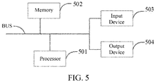
- FIG. 5 is a block diagram of an electronic device of the method for detecting an obstacle according to an embodiment of the present disclosure.
- the electronic device is intended to represent various forms of digital computers, such as laptop computers, desktop computers, worktables, personal digital assistants, servers, blade servers, large-scale computers, and other suitable computers.
- the electronic device may also represent various forms of mobile devices, such as personal digital assistants, cellular telephones, smart phones, wearable devices, and other similar computing devices.
- the components shown herein, their connections and relationships, and their functions are by way of example only and are not intended to limit the implementations of the present disclosure as described and/or claimed herein.
- the electronic device includes one or more processors 501, a memory 502, and an interface for connecting components, including a high-speed interface and a low-speed interface.
- the various components are connected to each other by different buses, and may be mounted on a common motherboard or installed in other ways as desired.
- the processor may process instructions executed within the electronic device, including instructions stored in or on a memory to display graphical information of the GUI on an external input/output device, such as a display device coupled to the interface.
- multiple processors and/or multiple buses may be used with multiple memories, if desired.
- a plurality of electronic devices may be connected, each providing a portion of necessary operations (e.g., as a server array, a set of blade servers, or a multiprocessor system).
- one processor 501 is taken as an example in Fig. 5 .
- the memory 502 is a non-transitory computer readable storage medium provided herein.
- the memory stores instructions executable by at least one processor, to cause the at least one processor to perform the method for detecting an obstacle provided herein.
- the non-transitory computer-readable storage medium of the present disclosure stores computer instructions for causing a computer to perform the method for detecting an obstacle provided herein.
- the memory 502 may be used to store non-transitory software programs, non-transitory computer executable programs, and modules, for example, the program instructions/modules corresponding to the method for detecting an obstacle in the embodiments of the present disclosure (for example, the radar detection module 301, the camera detection module 302, the extraction module 303, and the fusion detection module 304 shown in Fig. 3 ).
- the processor 501 runs the software programs, instructions and modules stored in the memory 502 to execute various functional applications and data processing of a server, that is, to implement the method for detecting an obstacle of the above method embodiments.
- the memory 502 may include a program storage area and a data storage area.
- the program storage area may store an operating system and an application required for at least one function.
- the data storage area may store data and the like created according to the usage of an electronic device according to the method for detecting an obstacle.
- the memory 502 may include a high-speed random access memory, and may also include a non-transitory memory, e.g., at least one disk storage device, a flash memory device or other non-volatile solid-state storage devices.
- the memory 502 may further include memories remotely arranged relative to the processor 501, where the remote memories may be connected to the electronic device of the method for detecting an obstacle by a network.
- An example of the above network includes but not limited to, the Internet, an enterprise intranet, a local area network, a mobile communications network, and a combination thereof.
- the electronic device of the method for detecting an obstacle may further include an input device 503 and an output device 504.
- the processor 501, the memory 502, the input device 503, and the output device 504 may be connected via a bus or in other modes. Connection by a bus is used as an example in Fig. 5 .
- the input device 503 may be used for receiving entered digit or character information, and generating a key signal input related to the user setting and function control of the electronic device of the method for detecting an obstacle, such as a touch screen, a keypad, a mouse, a track pad, a touch pad, a pointer bar, one or more mouse buttons, a trackball, a joystick, or the like.
- the output device 504 may include a display device, an auxiliary illumination device (e.g., an LED), a tactile feedback device (e.g., a vibration motor), and the like.
- the display device may include, but is not limited to, a liquid crystal display (LCD), a light emitting diode (LED) display, and a plasma display. In some embodiments, the display device may be a touch screen.
- the various embodiments of the systems and techniques described herein may be implemented in digital electronic circuit systems, integrated circuit systems, application specific ASICs (application specific integrated circuits), computer hardware, firmware, software, and/or combinations thereof. These various embodiments may include: being implemented in one or more computer programs that may be executed and/or interpreted on a programmable system including at least one programmable processor which may be a dedicated or general purpose programmable processor, it may receive data and instructions from a memory system, at least one input device, and at least one output device, and transmit the data and instructions to the memory system, the at least one input device, and the at least one output device.
- a programmable processor which may be a dedicated or general purpose programmable processor, it may receive data and instructions from a memory system, at least one input device, and at least one output device, and transmit the data and instructions to the memory system, the at least one input device, and the at least one output device.
- machine-readable medium and “computer-readable medium” refer to any computer program product, device, and/or device (e.g., magnetic disk, optical disk, memory, programmable logic device (PLD)) for providing machine instructions and/or data to a programmable processor, including a machine-readable medium that receives machine instructions as machine-readable signals.
- machine readable signal refers to any signal used to provide machine instructions and/or data to a programmable processor.
- the systems and techniques described herein may be implemented on a computer having a display device (e.g., a CRT (cathode ray tube) or LCD (liquid crystal display) monitor) for displaying information to the user and a keyboard and a pointing device (e.g., a mouse or a trackball) through which a user can provide input to the computer.
- a display device e.g., a CRT (cathode ray tube) or LCD (liquid crystal display) monitor
- a keyboard and a pointing device e.g., a mouse or a trackball
- Other types of devices may also be used to provide interaction with a user.
- the feedback provided to the user may be any form of sensory feedback (e.g., visual feedback, auditory feedback, or tactile feedback).
- the input in any form, including acoustic input, speech input, or tactile input, may be received from the user.
- the systems and techniques described herein may be implemented in a computing system including a backend component (e.g., as a data server), or a computing system including a middleware component (e.g., an application server), or a computing system including a front-end component (e.g., a personal computer having a graphical user interface or a web browser through which a user may interact with embodiments of the systems and techniques described herein), or a computing system including any combination of such backend component, middleware component, or front-end component.
- the components of the system may be interconnected by any form or medium of digital data communication (e.g., a communication network). Examples of communication networks include local region networks (LANs), wide region networks (WANs), the Internet, and block chain networks.
- the computer system may include a client and a server.
- the client and server are typically remote from each other and typically interact through a communication network.
- the relationship between the client and the server is generated by a computer program running on the corresponding computer and having a client-server relationship with each other.
Landscapes
- Engineering & Computer Science (AREA)
- Radar, Positioning & Navigation (AREA)
- Remote Sensing (AREA)
- Physics & Mathematics (AREA)
- General Physics & Mathematics (AREA)
- Computer Networks & Wireless Communication (AREA)
- Theoretical Computer Science (AREA)
- Multimedia (AREA)
- Mechanical Engineering (AREA)
- Electromagnetism (AREA)
- Transportation (AREA)
- Automation & Control Theory (AREA)
- Evolutionary Computation (AREA)
- Artificial Intelligence (AREA)
- Computer Vision & Pattern Recognition (AREA)
- Mathematical Physics (AREA)
- Computational Linguistics (AREA)
- Molecular Biology (AREA)
- Computing Systems (AREA)
- General Engineering & Computer Science (AREA)
- General Health & Medical Sciences (AREA)
- Software Systems (AREA)
- Data Mining & Analysis (AREA)
- Biophysics (AREA)
- Human Computer Interaction (AREA)
- Biomedical Technology (AREA)
- Life Sciences & Earth Sciences (AREA)
- Health & Medical Sciences (AREA)
- Signal Processing (AREA)
- Traffic Control Systems (AREA)
- Radar Systems Or Details Thereof (AREA)
Claims (7)
- Verfahren zum Erfassen eines Hindernisses, das Folgendes umfasst:Erfassen (S201) von Positionspunkten von Kandidatenhindernissen vor einem Fahrzeug durch einen Millimeterwellenradar;Erfassen (S202) einer linken Straßenbegrenzungslinie und einer rechten Straßenbegrenzungslinie einer Straße, auf der sich ein Fahrzeug befindet, durch eine Kamera;Trennen (S203) der Positionspunkte der Kandidatenhindernisse gemäß der linken Straßenbegrenzungslinie und der rechten Straßenbegrenzungslinie der Straße, auf der sich das Fahrzeug befindet, und Extrahieren von Positionspunkten zwischen der linken Straßenbegrenzungslinie und der rechten Straßenbegrenzungslinie;Projizieren (S204) der Positionspunkte zwischen der linken Straßenbegrenzungslinie und der rechten Straßenbegrenzungslinie auf ein Bild;Erfassen (S204) von Bereichen von Interesse, ROIs, die den Projektionspunkten entsprechen, auf dem Bild, wobei die ROIs, die den Projektionspunkten entsprechen, Bereiche mit regelmäßigen Formen sind, die auf den Positionspunkten zentriert sind;Berechnen (S205) von Erfassungsergebnissen der ROIs, die den Projektionspunkten entsprechen, durch ein tiefes Faltungsnetzwerk, wobei ein Erfassungsergebnis Folgendes umfasst: ein Erfassungsergebnis, das das Vorhandensein eines Hindernisses anzeigt, oder ein Erfassungsergebnis, das das Nichtvorhandensein eines Hindernisses anzeigt; undErfassen (S206) des Zielhindernisses vor dem Fahrzeug gemäß den Erfassungsergebnissen der ROIs, die den Projektionspunkten entsprechen,wobei das Verfahren nach dem Berechnen (S205) der Erfassungsergebnisse der ROIs, die den Projektionspunkten entsprechen, durch das tiefe Faltungsnetzwerk und vor dem Erfassen (S206) des Zielhindernisses vor dem Fahrzeug gemäß den Erfassungsergebnissen der ROIs, die den Projektionspunkten entsprechen, ferner Folgendes umfasst:Extrahieren von Projektionspunkten der fälschlicherweise erfassten Positionspunkte auf dem Bild aus dem Bild, basierend auf vorbestimmten Positionspunkten, die fälschlicherweise von dem Radar erfasst wurden;Herausfiltern der Projektionspunkte der fälschlicherweise erfassten Positionspunkte und der Erfassungsergebnisse von ROIs, die den Projektionspunkten entsprechen, der fälschlicherweise erfassten Positionspunkte in den Erfassungsergebnissen der ROIs, die den Projektionspunkten entsprechen, die von dem tiefen Faltungsnetzwerk ausgegeben werden; undBestimmen des Hindernisses vor dem Fahrzeug basierend auf Erfassungsergebnissen von ROIs, die Projektionspunkten entsprechen, nach der Filterung.
- Verfahren nach Anspruch 1, wobei das Berechnen (S205) der Erfassungsergebnisse der ROIs, die den Projektionspunkten entsprechen, durch das tiefe Faltungsnetzwerk Folgendes umfasst:Eingeben von ROIs, die den Projektionspunkten entsprechen, in das tiefe Faltungsnetzwerk;Erfassen von Wahrnehmungsergebnissen der Positionspunkte in den ROIs, die den Projektionspunkten entsprechen;Berechnen der Erfassungsergebnisse der ROIs, die den Projektionspunkten entsprechen, basierend auf den Wahrnehmungsergebnissen der Positionspunkte; undAusgeben der Erfassungsergebnisse der ROIs, die den Projektionspunkten entsprechen, durch das tiefe Faltungsnetzwerk.
- Verfahren nach Anspruch 1, wobei das Erfassen (S204) des Zielhindernisses vor dem Fahrzeug basierend auf den Projektionspunkten der Positionspunkte auf dem Bild Folgendes umfasst:Erfassen eines Typs des Zielhindernisses gemäß Projektionspunkten der Positionspunkte auf dem Bild; undBerechnen eines Abstands zwischen dem Zielhindernis und dem Fahrzeug basierend auf den Projektionspunkten der Positionspunkte auf dem Bild und vorbestimmten Positionspunkten, die von dem Fahrzeug eingenommen werden.
- Vorrichtung (300) zum Erfassen eines Hindernisses, die Folgendes umfasst:ein Radarerfassungsmodul (301), ein Kameraerfassungsmodul (302), ein Extraktionsmodul (303) und ein Fusionserfassungsmodul (304); wobeidas Radarerfassungsmodul (301) konfiguriert ist, um Positionspunkte von Kandidatenhindernissen vor einem Fahrzeug durch einen Millimeterwellenradar zu erfassen (S201);das Kameraerfassungsmodul (302) konfiguriert ist, um eine linke Straßenbegrenzungslinie und eine rechte Straßenbegrenzungslinie einer Straße, auf der sich ein Fahrzeug befindet, durch eine Kamera zu erfassen (S202);das Extraktionsmodul (303) konfiguriert ist, um die Positionspunkte der Kandidatenhindernisse gemäß der linken Straßenbegrenzungslinie und der rechten Straßenbegrenzungslinie der Straße zu trennen (S203), auf der sich das Fahrzeug befindet, und Positionspunkte zwischen der linken Straßenbegrenzungslinie und der rechten Straßenbegrenzungslinie zu extrahieren;das Fusionserfassungsmodul (304) konfiguriert ist, um die Positionspunkte zwischen der linken Straßenbegrenzungslinie und der rechten Straßenbegrenzungslinie auf ein Bild zu projizieren (S204) und ferner ein Beschaffungsuntermodul (3041), ein Berechnungsuntermodul (3042), ein Erfassungsuntermodul (3043) und ein Filterungsuntermodul umfasst, wobeidas Beschaffungsuntermodul (3041) konfiguriert ist zum: Erhalten (S204) von Bereichen von Interesse, ROIs, die den Projektionspunkten entsprechen, auf dem Bild, wobei die ROIs, die den Projektionspunkten entsprechen, Bereiche mit regelmäßigen Formen sind, die auf den Positionspunkten zentriert sind;das Berechnungsuntermodul (3042) konfiguriert ist zum: Berechnen (S205) von Erfassungsergebnissen der ROIs, die den Projektionspunkten entsprechen, durch ein tiefes Faltungsnetzwerk, wobei ein Erfassungsergebnis Folgendes umfasst: ein Erfassungsergebnis, das das Vorhandensein eines Hindernisses anzeigt, oder ein Erfassungsergebnis, das das Nichtvorhandensein eines Hindernisses anzeigt; unddas Erfassungsuntermodul (3043) konfiguriert ist zum: Erfassen (S206) des Zielhindernisses vor dem Fahrzeug gemäß den Erfassungsergebnissen der ROIs, die den Projektionspunkten entsprechen,das Filterungsuntermodul konfiguriert ist zum:Extrahieren von Projektionspunkten der fälschlicherweise erfassten Positionspunkte auf dem Bild aus dem Bild, basierend auf vorbestimmten Positionspunkten, die fälschlicherweise von dem Radar erfasst wurden, undHerausfiltern der Projektionspunkte der fälschlicherweise erfassten Positionspunkte und der Erfassungsergebnisse von ROIs, die den Projektionspunkten entsprechen, der fälschlicherweise erfassten Positionspunkte der fälschlicherweise erfassten Positionspunkte in den Erfassungsergebnissen der ROIs, die den Projektionspunkten entsprechen, die von dem tiefen Faltungsnetzwerk ausgegeben werden; unddas Erfassungsuntermodul konfiguriert ist zum: Bestimmen des Hindernisses vor dem Fahrzeug basierend auf Erfassungsergebnissen von ROIs, die Projektionspunkten entsprechen, nach der Filterung.
- Vorrichtung nach Anspruch 4, wobei das Berechnungsuntermodul (3042) ferner konfiguriert ist zum:Eingeben von ROIs, die den Projektionspunkten entsprechen, in das tiefe Faltungsnetzwerk;Erhalten von Wahrnehmungsergebnissen der Positionspunkte in den ROIs, die den Projektionspunkten entsprechen;Berechnen der Erfassungsergebnisse der ROIs, die den Projektionspunkten entsprechen, basierend auf den Wahrnehmungsergebnissen der Positionspunkte; undAusgeben der Erfassungsergebnisse der ROIs, die den Projektionspunkten entsprechen, durch das tiefe Faltungsnetzwerk.
- Vorrichtung nach Anspruch 4, wobei das Fusionserfassungsmodul (304) ferner konfiguriert ist zum:Erfassen eines Typs des Zielhindernisses gemäß Projektionspunkten der Positionspunkte auf dem Bild; undBerechnen eines Abstands zwischen dem Zielhindernis und dem Fahrzeug basierend auf den Projektionspunkten der Positionspunkte auf dem Bild und vorbestimmten Positionspunkten, die von dem Fahrzeug eingenommen werden.
- Nichtflüchtiges computerlesbares Speichermedium, das Computeranweisungen speichert, wobei die Computeranweisungen, wenn sie von einer Vorrichtung nach einem der Ansprüche 4 bis 6 ausgeführt werden, die Vorrichtung veranlassen, das Verfahren nach einem der Ansprüche 1-3 auszuführen.
Applications Claiming Priority (1)
| Application Number | Priority Date | Filing Date | Title |
|---|---|---|---|
| CN202010166864.6A CN111401208B (zh) | 2020-03-11 | 2020-03-11 | 一种障碍物检测方法、装置、电子设备及存储介质 |
Publications (2)
| Publication Number | Publication Date |
|---|---|
| EP3879307A1 EP3879307A1 (de) | 2021-09-15 |
| EP3879307B1 true EP3879307B1 (de) | 2023-03-08 |
Family
ID=71436169
Family Applications (1)
| Application Number | Title | Priority Date | Filing Date |
|---|---|---|---|
| EP20196156.2A Active EP3879307B1 (de) | 2020-03-11 | 2020-09-15 | Verfahren und vorrichtung zur detektion eines hindernisses |
Country Status (5)
| Country | Link |
|---|---|
| US (1) | US11468689B2 (de) |
| EP (1) | EP3879307B1 (de) |
| JP (1) | JP7339934B2 (de) |
| KR (1) | KR102407504B1 (de) |
| CN (1) | CN111401208B (de) |
Families Citing this family (28)
| Publication number | Priority date | Publication date | Assignee | Title |
|---|---|---|---|---|
| EP3882813B1 (de) | 2020-03-20 | 2025-05-07 | Aptiv Technologies AG | Verfahren zur erzeugung eines dynamischen belegungsrasters |
| EP3888988B1 (de) | 2020-03-30 | 2024-09-04 | Aptiv Technologies AG | Verfahren und system zur bestimmung eines nutzbaren abstands vor einem fahrzeug |
| EP3905105A1 (de) | 2020-04-27 | 2021-11-03 | Aptiv Technologies Limited | Verfahren zur bestimmung eines kollisionsfreien raumes |
| EP3905106A1 (de) | 2020-04-27 | 2021-11-03 | Aptiv Technologies Limited | Verfahren zur bestimmung einer befahrbaren fläche |
| CN111856440B (zh) | 2020-07-21 | 2024-04-05 | 阿波罗智联(北京)科技有限公司 | 位置检测方法、装置、设备及可读存储介质 |
| CN112163446B (zh) * | 2020-08-12 | 2023-04-28 | 浙江吉利汽车研究院有限公司 | 一种障碍物检测方法、装置、电子设备及存储介质 |
| CN112485797B (zh) * | 2020-10-27 | 2021-08-03 | 湖北亿咖通科技有限公司 | 用于pdc系统的障碍物距离计算方法、装置和计算机设备 |
| US11688176B2 (en) * | 2020-10-30 | 2023-06-27 | Nauto, Inc. | Devices and methods for calibrating vehicle cameras |
| EP4001962A1 (de) | 2020-11-23 | 2022-05-25 | Aptiv Technologies Limited | Vorrichtung, verfahren und programm zur bestimmung vom freien raum |
| CN114537381B (zh) * | 2020-11-24 | 2024-05-31 | 宇通客车股份有限公司 | 一种自动驾驶车辆的车道避障方法及装置 |
| EP4009228B1 (de) | 2020-12-02 | 2025-10-29 | Aptiv Technologies AG | Verfahren zur bestimmung eines semantischen freiraums |
| US11754666B2 (en) * | 2021-02-12 | 2023-09-12 | Aptiv Technologies Limited | Radar detection prioritization based on downstream feedback |
| CN113619606B (zh) * | 2021-09-17 | 2024-06-14 | 中国第一汽车股份有限公司 | 障碍物确定方法、装置、设备以及存储介质 |
| CN114037972B (zh) * | 2021-10-08 | 2024-08-13 | 岚图汽车科技有限公司 | 目标检测方法、装置、设备及可读存储介质 |
| CN113960554A (zh) * | 2021-10-18 | 2022-01-21 | 北京市首发高速公路建设管理有限责任公司 | 基于毫米波雷达的隧道内交通目标定位方法及装置 |
| CN114463717B (zh) * | 2021-12-30 | 2025-10-10 | 武汉中海庭数据技术有限公司 | 一种障碍物位置判断方法、系统、电子设备及存储介质 |
| CN114359869B (zh) * | 2021-12-31 | 2025-09-09 | 中国第一汽车股份有限公司 | 检测车辆行驶区域上的边界的方法和装置 |
| CN114332647B (zh) * | 2021-12-31 | 2022-10-21 | 合肥工业大学 | 一种用于无人船的河道边界检测与跟踪方法及系统 |
| CN114353593B (zh) * | 2022-01-10 | 2024-04-09 | 北京机械设备研究所 | 特定目标防控方法、装置、电子设备以及存储介质 |
| CN114564018B (zh) * | 2022-02-24 | 2025-03-21 | 深圳市优必选科技股份有限公司 | 控制方法、控制装置、终端设备及计算机可读存储介质 |
| CN115063760B (zh) * | 2022-05-20 | 2024-11-12 | 广州文远知行科技有限公司 | 车辆可行驶区域检测方法、装置、设备及存储介质 |
| CN115937325B (zh) * | 2022-09-27 | 2023-06-23 | 上海几何伙伴智能驾驶有限公司 | 一种结合毫米波雷达信息的车端摄像头标定方法 |
| CN117975404B (zh) * | 2022-10-26 | 2024-10-25 | 北京三快在线科技有限公司 | 朝向信息确定方法以及自动驾驶车辆 |
| CN115808929B (zh) * | 2023-01-19 | 2023-04-14 | 禾多科技(北京)有限公司 | 车辆仿真避障方法、装置、电子设备和计算机可读介质 |
| CN115861975B (zh) * | 2023-02-28 | 2023-05-12 | 杭州枕石智能科技有限公司 | 障碍物车辆位姿估计方法及设备 |
| CN116461473B (zh) * | 2023-03-30 | 2025-11-21 | 重庆长安汽车软件科技有限公司 | 道路障碍物的确定方法、装置、设备和存储介质 |
| CN116486377B (zh) * | 2023-04-26 | 2023-12-26 | 小米汽车科技有限公司 | 可行驶区域的生成方法及装置 |
| DE102024107253A1 (de) | 2024-03-14 | 2025-09-18 | Audi Aktiengesellschaft | Verfahren zum Betreiben eines Steuergeräts für ein Kraftfahrzeug sowie entsprechendes Steuergerät |
Family Cites Families (18)
| Publication number | Priority date | Publication date | Assignee | Title |
|---|---|---|---|---|
| JP3245363B2 (ja) * | 1996-08-29 | 2002-01-15 | 富士重工業株式会社 | 車両の衝突防止装置 |
| JPH1116099A (ja) * | 1997-06-27 | 1999-01-22 | Hitachi Ltd | 自動車走行支援装置 |
| JP2007104171A (ja) * | 2005-10-03 | 2007-04-19 | Omron Corp | 前方監視装置 |
| US7676087B2 (en) * | 2006-09-20 | 2010-03-09 | Delphi Technologies, Inc. | Method for identifying vehicles in electronic images |
| US8355539B2 (en) * | 2007-09-07 | 2013-01-15 | Sri International | Radar guided vision system for vehicle validation and vehicle motion characterization |
| JP2010061587A (ja) | 2008-09-05 | 2010-03-18 | Nippon Telegr & Teleph Corp <Ntt> | 類似文書判定装置、類似判定方法およびそのプログラム |
| JP4434296B1 (ja) * | 2008-09-05 | 2010-03-17 | トヨタ自動車株式会社 | 物体検出装置 |
| JP6441558B2 (ja) | 2013-07-23 | 2018-12-19 | 株式会社Soken | 物体位置判定装置 |
| KR101568683B1 (ko) | 2013-11-13 | 2015-11-12 | 주식회사 하나비전테크 | 영상 분석을 이용한 차간 거리 추정 방법 및 그 장치 |
| US9760806B1 (en) * | 2016-05-11 | 2017-09-12 | TCL Research America Inc. | Method and system for vision-centric deep-learning-based road situation analysis |
| US10495753B2 (en) * | 2016-09-19 | 2019-12-03 | Nec Corporation | Video to radar |
| KR101976952B1 (ko) | 2017-11-01 | 2019-05-09 | 재단법인 다차원 스마트 아이티 융합시스템 연구단 | 움직임 벡터를 이용한 객체 검출 시스템 및 그 방법 |
| CN107862287A (zh) * | 2017-11-08 | 2018-03-30 | 吉林大学 | 一种前方小区域物体识别及车辆预警方法 |
| CN108983219B (zh) * | 2018-08-17 | 2020-04-07 | 北京航空航天大学 | 一种交通场景的图像信息和雷达信息的融合方法及系统 |
| CN109271944B (zh) * | 2018-09-27 | 2021-03-12 | 百度在线网络技术(北京)有限公司 | 障碍物检测方法、装置、电子设备、车辆及存储介质 |
| CN109583416B (zh) * | 2018-12-11 | 2021-04-13 | 广州小鹏汽车科技有限公司 | 伪车道线识别方法及系统 |
| WO2020140047A1 (en) * | 2018-12-28 | 2020-07-02 | Nvidia Corporation | Distance to obstacle detection in autonomous machine applications |
| CN109669168A (zh) * | 2019-01-21 | 2019-04-23 | 成都玻尔兹曼科技有限公司 | 一种基于深度学习的雷达虚警剔除方法 |
-
2020
- 2020-03-11 CN CN202010166864.6A patent/CN111401208B/zh active Active
- 2020-09-10 US US17/017,508 patent/US11468689B2/en active Active
- 2020-09-15 JP JP2020154211A patent/JP7339934B2/ja active Active
- 2020-09-15 EP EP20196156.2A patent/EP3879307B1/de active Active
- 2020-09-25 KR KR1020200125093A patent/KR102407504B1/ko active Active
Also Published As
| Publication number | Publication date |
|---|---|
| CN111401208A (zh) | 2020-07-10 |
| JP7339934B2 (ja) | 2023-09-06 |
| EP3879307A1 (de) | 2021-09-15 |
| JP2021144677A (ja) | 2021-09-24 |
| CN111401208B (zh) | 2023-09-22 |
| KR20210116186A (ko) | 2021-09-27 |
| US11468689B2 (en) | 2022-10-11 |
| US20210287019A1 (en) | 2021-09-16 |
| KR102407504B1 (ko) | 2022-06-13 |
Similar Documents
| Publication | Publication Date | Title |
|---|---|---|
| EP3879307B1 (de) | Verfahren und vorrichtung zur detektion eines hindernisses | |
| CN112415552B (zh) | 车辆位置的确定方法、装置及电子设备 | |
| EP3968266B1 (de) | Verfahren und vorrichtung zur dreidimensionalen positionserfassung von hindernissen für eine vorrichtung zur strassenseitigen datenverarbeitung | |
| US11586218B2 (en) | Method and apparatus for positioning vehicle, electronic device and storage medium | |
| CN111324115B (zh) | 障碍物位置检测融合方法、装置、电子设备和存储介质 | |
| JP7241057B2 (ja) | 車両測位方法、装置、電子機器、車両及び記憶媒体 | |
| EP3910533B1 (de) | Verfahren, vorrichtung, elektronische vorrichtung und speichermedium zur überwachung einer bilderfassungsvorrichtung | |
| US11828604B2 (en) | Method and apparatus for positioning vehicle, electronic device, and storage medium | |
| CN111611901B (zh) | 车辆逆行检测方法、装置、设备以及存储介质 | |
| EP3919930B1 (de) | Verfahren und vorrichtung zur bestimmung der geschwindigkeit eines hindernisses, vorrichtung, medium und computerprogrammprodukt | |
| CN111753765A (zh) | 感知设备的检测方法、装置、设备及存储介质 | |
| CN114639079A (zh) | 匹配车道线数据的方法、装置、设备和存储介质 | |
| EP3901581A2 (de) | Verfahren, einrichtung, vorrichtung und speichermedium zur bestimmung der fahrspur, in der sich ein fahrzeug befindet | |
| CN112184914B (zh) | 目标对象三维位置的确定方法、装置和路侧设备 | |
| CN111767843B (zh) | 三维位置预测方法、装置、设备以及存储介质 | |
| CN112184828B (zh) | 激光雷达与摄像头的外参标定方法、装置及自动驾驶车辆 | |
| CN111721305B (zh) | 定位方法和装置、自动驾驶车辆、电子设备和存储介质 | |
| CN111310840A (zh) | 数据融合处理方法、装置、设备和存储介质 | |
| CN113985413A (zh) | 点云数据的处理方法、装置、设备和自动驾驶车辆 | |
| CN112528846A (zh) | 障碍物检测的测评方法、装置、设备以及存储介质 | |
| CN117168470A (zh) | 一种定位信息的确定方法、装置、电子设备和存储介质 | |
| CN111198370A (zh) | 毫米波雷达背景检测方法、装置、电子设备及存储介质 | |
| CN111784659B (zh) | 图像检测的方法、装置、电子设备以及存储介质 | |
| US20210215797A1 (en) | Object detection apparatus, vehicle, object detection method, and computer readable medium | |
| US20200118284A1 (en) | Object detection system |
Legal Events
| Date | Code | Title | Description |
|---|---|---|---|
| PUAI | Public reference made under article 153(3) epc to a published international application that has entered the european phase |
Free format text: ORIGINAL CODE: 0009012 |
|
| STAA | Information on the status of an ep patent application or granted ep patent |
Free format text: STATUS: REQUEST FOR EXAMINATION WAS MADE |
|
| 17P | Request for examination filed |
Effective date: 20200915 |
|
| AK | Designated contracting states |
Kind code of ref document: A1 Designated state(s): AL AT BE BG CH CY CZ DE DK EE ES FI FR GB GR HR HU IE IS IT LI LT LU LV MC MK MT NL NO PL PT RO RS SE SI SK SM TR |
|
| RAP1 | Party data changed (applicant data changed or rights of an application transferred) |
Owner name: APOLLO INTELLIGENT DRIVING TECHNOLOGY (BEIJING) CO., LTD. |
|
| STAA | Information on the status of an ep patent application or granted ep patent |
Free format text: STATUS: EXAMINATION IS IN PROGRESS |
|
| 17Q | First examination report despatched |
Effective date: 20220525 |
|
| GRAP | Despatch of communication of intention to grant a patent |
Free format text: ORIGINAL CODE: EPIDOSNIGR1 |
|
| STAA | Information on the status of an ep patent application or granted ep patent |
Free format text: STATUS: GRANT OF PATENT IS INTENDED |
|
| INTG | Intention to grant announced |
Effective date: 20221130 |
|
| GRAS | Grant fee paid |
Free format text: ORIGINAL CODE: EPIDOSNIGR3 |
|
| GRAA | (expected) grant |
Free format text: ORIGINAL CODE: 0009210 |
|
| STAA | Information on the status of an ep patent application or granted ep patent |
Free format text: STATUS: THE PATENT HAS BEEN GRANTED |
|
| AK | Designated contracting states |
Kind code of ref document: B1 Designated state(s): AL AT BE BG CH CY CZ DE DK EE ES FI FR GB GR HR HU IE IS IT LI LT LU LV MC MK MT NL NO PL PT RO RS SE SI SK SM TR |
|
| REG | Reference to a national code |
Ref country code: CH Ref legal event code: EP Ref country code: AT Ref legal event code: REF Ref document number: 1552951 Country of ref document: AT Kind code of ref document: T Effective date: 20230315 |
|
| REG | Reference to a national code |
Ref country code: IE Ref legal event code: FG4D |
|
| REG | Reference to a national code |
Ref country code: DE Ref legal event code: R096 Ref document number: 602020008672 Country of ref document: DE |
|
| REG | Reference to a national code |
Ref country code: LT Ref legal event code: MG9D |
|
| P01 | Opt-out of the competence of the unified patent court (upc) registered |
Effective date: 20230526 |
|
| REG | Reference to a national code |
Ref country code: NL Ref legal event code: MP Effective date: 20230308 |
|
| PG25 | Lapsed in a contracting state [announced via postgrant information from national office to epo] |
Ref country code: RS Free format text: LAPSE BECAUSE OF FAILURE TO SUBMIT A TRANSLATION OF THE DESCRIPTION OR TO PAY THE FEE WITHIN THE PRESCRIBED TIME-LIMIT Effective date: 20230308 Ref country code: NO Free format text: LAPSE BECAUSE OF FAILURE TO SUBMIT A TRANSLATION OF THE DESCRIPTION OR TO PAY THE FEE WITHIN THE PRESCRIBED TIME-LIMIT Effective date: 20230608 Ref country code: LV Free format text: LAPSE BECAUSE OF FAILURE TO SUBMIT A TRANSLATION OF THE DESCRIPTION OR TO PAY THE FEE WITHIN THE PRESCRIBED TIME-LIMIT Effective date: 20230308 Ref country code: LT Free format text: LAPSE BECAUSE OF FAILURE TO SUBMIT A TRANSLATION OF THE DESCRIPTION OR TO PAY THE FEE WITHIN THE PRESCRIBED TIME-LIMIT Effective date: 20230308 Ref country code: HR Free format text: LAPSE BECAUSE OF FAILURE TO SUBMIT A TRANSLATION OF THE DESCRIPTION OR TO PAY THE FEE WITHIN THE PRESCRIBED TIME-LIMIT Effective date: 20230308 Ref country code: ES Free format text: LAPSE BECAUSE OF FAILURE TO SUBMIT A TRANSLATION OF THE DESCRIPTION OR TO PAY THE FEE WITHIN THE PRESCRIBED TIME-LIMIT Effective date: 20230308 |
|
| REG | Reference to a national code |
Ref country code: AT Ref legal event code: MK05 Ref document number: 1552951 Country of ref document: AT Kind code of ref document: T Effective date: 20230308 |
|
| PG25 | Lapsed in a contracting state [announced via postgrant information from national office to epo] |
Ref country code: SE Free format text: LAPSE BECAUSE OF FAILURE TO SUBMIT A TRANSLATION OF THE DESCRIPTION OR TO PAY THE FEE WITHIN THE PRESCRIBED TIME-LIMIT Effective date: 20230308 Ref country code: NL Free format text: LAPSE BECAUSE OF FAILURE TO SUBMIT A TRANSLATION OF THE DESCRIPTION OR TO PAY THE FEE WITHIN THE PRESCRIBED TIME-LIMIT Effective date: 20230308 Ref country code: GR Free format text: LAPSE BECAUSE OF FAILURE TO SUBMIT A TRANSLATION OF THE DESCRIPTION OR TO PAY THE FEE WITHIN THE PRESCRIBED TIME-LIMIT Effective date: 20230609 Ref country code: FI Free format text: LAPSE BECAUSE OF FAILURE TO SUBMIT A TRANSLATION OF THE DESCRIPTION OR TO PAY THE FEE WITHIN THE PRESCRIBED TIME-LIMIT Effective date: 20230308 |
|
| PG25 | Lapsed in a contracting state [announced via postgrant information from national office to epo] |
Ref country code: SM Free format text: LAPSE BECAUSE OF FAILURE TO SUBMIT A TRANSLATION OF THE DESCRIPTION OR TO PAY THE FEE WITHIN THE PRESCRIBED TIME-LIMIT Effective date: 20230308 Ref country code: RO Free format text: LAPSE BECAUSE OF FAILURE TO SUBMIT A TRANSLATION OF THE DESCRIPTION OR TO PAY THE FEE WITHIN THE PRESCRIBED TIME-LIMIT Effective date: 20230308 Ref country code: PT Free format text: LAPSE BECAUSE OF FAILURE TO SUBMIT A TRANSLATION OF THE DESCRIPTION OR TO PAY THE FEE WITHIN THE PRESCRIBED TIME-LIMIT Effective date: 20230710 Ref country code: EE Free format text: LAPSE BECAUSE OF FAILURE TO SUBMIT A TRANSLATION OF THE DESCRIPTION OR TO PAY THE FEE WITHIN THE PRESCRIBED TIME-LIMIT Effective date: 20230308 Ref country code: CZ Free format text: LAPSE BECAUSE OF FAILURE TO SUBMIT A TRANSLATION OF THE DESCRIPTION OR TO PAY THE FEE WITHIN THE PRESCRIBED TIME-LIMIT Effective date: 20230308 Ref country code: AT Free format text: LAPSE BECAUSE OF FAILURE TO SUBMIT A TRANSLATION OF THE DESCRIPTION OR TO PAY THE FEE WITHIN THE PRESCRIBED TIME-LIMIT Effective date: 20230308 |
|
| PG25 | Lapsed in a contracting state [announced via postgrant information from national office to epo] |
Ref country code: SK Free format text: LAPSE BECAUSE OF FAILURE TO SUBMIT A TRANSLATION OF THE DESCRIPTION OR TO PAY THE FEE WITHIN THE PRESCRIBED TIME-LIMIT Effective date: 20230308 Ref country code: PL Free format text: LAPSE BECAUSE OF FAILURE TO SUBMIT A TRANSLATION OF THE DESCRIPTION OR TO PAY THE FEE WITHIN THE PRESCRIBED TIME-LIMIT Effective date: 20230308 Ref country code: IS Free format text: LAPSE BECAUSE OF FAILURE TO SUBMIT A TRANSLATION OF THE DESCRIPTION OR TO PAY THE FEE WITHIN THE PRESCRIBED TIME-LIMIT Effective date: 20230708 |
|
| REG | Reference to a national code |
Ref country code: DE Ref legal event code: R097 Ref document number: 602020008672 Country of ref document: DE |
|
| PLBE | No opposition filed within time limit |
Free format text: ORIGINAL CODE: 0009261 |
|
| STAA | Information on the status of an ep patent application or granted ep patent |
Free format text: STATUS: NO OPPOSITION FILED WITHIN TIME LIMIT |
|
| PG25 | Lapsed in a contracting state [announced via postgrant information from national office to epo] |
Ref country code: SI Free format text: LAPSE BECAUSE OF FAILURE TO SUBMIT A TRANSLATION OF THE DESCRIPTION OR TO PAY THE FEE WITHIN THE PRESCRIBED TIME-LIMIT Effective date: 20230308 Ref country code: DK Free format text: LAPSE BECAUSE OF FAILURE TO SUBMIT A TRANSLATION OF THE DESCRIPTION OR TO PAY THE FEE WITHIN THE PRESCRIBED TIME-LIMIT Effective date: 20230308 |
|
| 26N | No opposition filed |
Effective date: 20231211 |
|
| REG | Reference to a national code |
Ref country code: CH Ref legal event code: PL |
|
| PG25 | Lapsed in a contracting state [announced via postgrant information from national office to epo] |
Ref country code: LU Free format text: LAPSE BECAUSE OF NON-PAYMENT OF DUE FEES Effective date: 20230915 |
|
| REG | Reference to a national code |
Ref country code: BE Ref legal event code: MM Effective date: 20230930 |
|
| PG25 | Lapsed in a contracting state [announced via postgrant information from national office to epo] |
Ref country code: LU Free format text: LAPSE BECAUSE OF NON-PAYMENT OF DUE FEES Effective date: 20230915 Ref country code: IT Free format text: LAPSE BECAUSE OF FAILURE TO SUBMIT A TRANSLATION OF THE DESCRIPTION OR TO PAY THE FEE WITHIN THE PRESCRIBED TIME-LIMIT Effective date: 20230308 Ref country code: MC Free format text: LAPSE BECAUSE OF FAILURE TO SUBMIT A TRANSLATION OF THE DESCRIPTION OR TO PAY THE FEE WITHIN THE PRESCRIBED TIME-LIMIT Effective date: 20230308 |
|
| REG | Reference to a national code |
Ref country code: IE Ref legal event code: MM4A |
|
| PG25 | Lapsed in a contracting state [announced via postgrant information from national office to epo] |
Ref country code: IE Free format text: LAPSE BECAUSE OF NON-PAYMENT OF DUE FEES Effective date: 20230915 |
|
| PG25 | Lapsed in a contracting state [announced via postgrant information from national office to epo] |
Ref country code: CH Free format text: LAPSE BECAUSE OF NON-PAYMENT OF DUE FEES Effective date: 20230930 |
|
| PG25 | Lapsed in a contracting state [announced via postgrant information from national office to epo] |
Ref country code: IE Free format text: LAPSE BECAUSE OF NON-PAYMENT OF DUE FEES Effective date: 20230915 Ref country code: CH Free format text: LAPSE BECAUSE OF NON-PAYMENT OF DUE FEES Effective date: 20230930 |
|
| PG25 | Lapsed in a contracting state [announced via postgrant information from national office to epo] |
Ref country code: BE Free format text: LAPSE BECAUSE OF NON-PAYMENT OF DUE FEES Effective date: 20230930 |
|
| PG25 | Lapsed in a contracting state [announced via postgrant information from national office to epo] |
Ref country code: BG Free format text: LAPSE BECAUSE OF FAILURE TO SUBMIT A TRANSLATION OF THE DESCRIPTION OR TO PAY THE FEE WITHIN THE PRESCRIBED TIME-LIMIT Effective date: 20230308 |
|
| PG25 | Lapsed in a contracting state [announced via postgrant information from national office to epo] |
Ref country code: BG Free format text: LAPSE BECAUSE OF FAILURE TO SUBMIT A TRANSLATION OF THE DESCRIPTION OR TO PAY THE FEE WITHIN THE PRESCRIBED TIME-LIMIT Effective date: 20230308 |
|
| GBPC | Gb: european patent ceased through non-payment of renewal fee |
Effective date: 20240915 |
|
| PG25 | Lapsed in a contracting state [announced via postgrant information from national office to epo] |
Ref country code: GB Free format text: LAPSE BECAUSE OF NON-PAYMENT OF DUE FEES Effective date: 20240915 |
|
| PG25 | Lapsed in a contracting state [announced via postgrant information from national office to epo] |
Ref country code: CY Free format text: LAPSE BECAUSE OF FAILURE TO SUBMIT A TRANSLATION OF THE DESCRIPTION OR TO PAY THE FEE WITHIN THE PRESCRIBED TIME-LIMIT; INVALID AB INITIO Effective date: 20200915 |
|
| PG25 | Lapsed in a contracting state [announced via postgrant information from national office to epo] |
Ref country code: HU Free format text: LAPSE BECAUSE OF FAILURE TO SUBMIT A TRANSLATION OF THE DESCRIPTION OR TO PAY THE FEE WITHIN THE PRESCRIBED TIME-LIMIT; INVALID AB INITIO Effective date: 20200915 |
|
| PGFP | Annual fee paid to national office [announced via postgrant information from national office to epo] |
Ref country code: DE Payment date: 20250919 Year of fee payment: 6 |
|
| PGFP | Annual fee paid to national office [announced via postgrant information from national office to epo] |
Ref country code: FR Payment date: 20250728 Year of fee payment: 6 |
|
| PG25 | Lapsed in a contracting state [announced via postgrant information from national office to epo] |
Ref country code: TR Free format text: LAPSE BECAUSE OF FAILURE TO SUBMIT A TRANSLATION OF THE DESCRIPTION OR TO PAY THE FEE WITHIN THE PRESCRIBED TIME-LIMIT Effective date: 20230308 |