EP3878662A1 - Rad für fahrzeuge - Google Patents
Rad für fahrzeuge Download PDFInfo
- Publication number
- EP3878662A1 EP3878662A1 EP21161816.0A EP21161816A EP3878662A1 EP 3878662 A1 EP3878662 A1 EP 3878662A1 EP 21161816 A EP21161816 A EP 21161816A EP 3878662 A1 EP3878662 A1 EP 3878662A1
- Authority
- EP
- European Patent Office
- Prior art keywords
- wheel
- protective shell
- protective
- wheel body
- shell
- Prior art date
- Legal status (The legal status is an assumption and is not a legal conclusion. Google has not performed a legal analysis and makes no representation as to the accuracy of the status listed.)
- Withdrawn
Links
Images


Classifications
-
- B—PERFORMING OPERATIONS; TRANSPORTING
- B60—VEHICLES IN GENERAL
- B60B—VEHICLE WHEELS; CASTORS; AXLES FOR WHEELS OR CASTORS; INCREASING WHEEL ADHESION
- B60B17/00—Wheels characterised by rail-engaging elements
- B60B17/0006—Construction of wheel bodies, e.g. disc wheels
- B60B17/0013—Construction of wheel bodies, e.g. disc wheels formed by two or more axially spaced discs
- B60B17/0017—Construction of wheel bodies, e.g. disc wheels formed by two or more axially spaced discs with insonorisation means
-
- B—PERFORMING OPERATIONS; TRANSPORTING
- B60—VEHICLES IN GENERAL
- B60B—VEHICLE WHEELS; CASTORS; AXLES FOR WHEELS OR CASTORS; INCREASING WHEEL ADHESION
- B60B17/00—Wheels characterised by rail-engaging elements
- B60B17/0006—Construction of wheel bodies, e.g. disc wheels
- B60B17/0024—Construction of wheel bodies, e.g. disc wheels with noise reducing means
-
- B—PERFORMING OPERATIONS; TRANSPORTING
- B60—VEHICLES IN GENERAL
- B60B—VEHICLE WHEELS; CASTORS; AXLES FOR WHEELS OR CASTORS; INCREASING WHEEL ADHESION
- B60B37/00—Wheel-axle combinations, e.g. wheel sets
-
- B—PERFORMING OPERATIONS; TRANSPORTING
- B60—VEHICLES IN GENERAL
- B60B—VEHICLE WHEELS; CASTORS; AXLES FOR WHEELS OR CASTORS; INCREASING WHEEL ADHESION
- B60B2900/00—Purpose of invention
- B60B2900/20—Avoidance of
- B60B2900/212—Damage
Definitions
- the invention relates to a wheel for vehicles, in particular for running gears of rail vehicles, with a wheel body and a running surface.
- Wheels of vehicles e.g. rail vehicle wheels
- SISRAP Siemens Steel Rubber Axle Protection
- the wheel set shaft protection arrangement SISRAP is in the DE 10 2010 009 437 A1 disclosed.
- the WO 2018/166949 A1 a ballistic protection arrangement for vehicles, in which a wheel set shaft of a running gear of a rail vehicle is encased by means of a shell.
- the shell has at least one material layer made of at least one fiber material.
- the invention is based on the object of specifying a wheel which has been further developed compared to the prior art and is protected from impacting objects.
- this object is achieved with a wheel of the type mentioned at the outset, in which at least one first protective shell is connected to the wheel body, the at least first protective shell being connected to the wheel body by means of screws which are mounted in bores in the wheel body and the at least first protective shell is, with protective shims connected to the screws, which have recesses in which screw heads of the screws are provided.
- objects such as stones or gravel etc. cannot directly impact areas of the wheel body that are at risk, such as a wheel web, but are intercepted by the first protective shell. This avoids damage to the wheel and reduces the risk of premature wheel or wheel set replacement.
- the wheel can be protected on one side (for example on the outside of the vehicle) or on both sides.
- the first protective shell is provided on a first face of the wheel body, but no protective shell is arranged on a second face of the wheel body.
- the first protective shell is provided on the first face of the wheel body, and a second protective shell is provided on the second face of the wheel body.
- the first protective shell is on the one hand securely connected to the wheel body due to the screws and on the other hand, due to the recesses in the protective shims in which the screw heads of the screws are provided, the screws are also protected from impacting objects.
- the at least first protective shell is detachably connected to the wheel body.
- the first protective shell can be exchanged if it is damaged, for example, due to impacting objects.
- a preferred solution is achieved when the at least first protective shell is arranged to run along a wheel web.
- the at least first protective shell is arranged to extend as far as a central bore in a wheel hub. It is also advantageous if the at least first protective shell is arranged to extend up to a first end face of a wheel rim. As a result, a large part of the wheel body is covered by the first protective shell.
- a wheel brake disk is connected to the wheel body, the at least first protective shell having a radial extension of less than or equal to an inner radius of the wheel brake disk.
- a wheel brake disc is connected to the wheel body, the at least first protective shell being clamped between the wheel body and a first friction ring of the wheel brake disc.
- fastening means of the wheel brake disc and the first friction ring itself can be used to connect the first protective shell to the wheel body.
- a favorable embodiment is also obtained if the at least first protective shell is arranged in contact with the wheel body.
- the at least first protective shell is designed to follow a contour of the wheel body.
- a particularly compact wheel with a protective arrangement is achieved by this measure. Penetration of foreign bodies into an area between the wheel body and the first protective shell is avoided.
- the first protective shell in contact with the wheel body is also favorable aerodynamically and acoustically.
- the at least first protective shell is formed from individual protective shell elements.
- a protective shell element if a protective shell element is damaged, it can be replaced very quickly.
- the wheel is part of a wheelset with wheelset bearings, wheelset bearing housings, etc.
- the individual protective shell elements can be dismantled and assembled without removing wheelset components.
- only the protective shell element affected by damage and relatively small in relation to the total area of the first protective shell needs to be exchanged, while undamaged protective shell elements can remain mounted on the wheel body.
- the at least first protective shell has an outer first shell part made of metal and an inner second shell part made of elastomer, the second shell part being arranged facing the wheel body. A division of functions is thereby achieved. While the first shell part acts as a sturdy cover against the first Protective shell impacting objects acts, cushions and dampens the second shell part, which has a high energy absorption capacity, impacts against the first protective shell.
- a wheel set of a vehicle with two wheels each having at least one protective shell, one wheel set shaft having a wheel set shaft protective cover.
- the protective shells of the wheels are arranged so as to overlap the wheel set shaft protective casing. This results in corrosion protection in the transition areas between the wheelset shaft and the wheels.
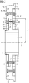
- Fig. 1 shows a side elevation of an exemplary first embodiment variant of a wheel according to the invention for a chassis of a rail vehicle in a sectional illustration.
- the wheel has a wheel body 1 with a wheel web 2 and a wheel hub 3.
- the wheel hub 3 in turn has a central bore 4 with a wheel axle 5.
- About the center hole 4 is an example in Fig. 5 illustrated wheelset shaft 6 can be connected to the wheel.
- the wheel body 1 furthermore comprises a wheel rim 7 with a wheel rim 8.
- a running surface 9 is also provided on the circumference of the wheel, via which the wheel can be placed on an in Fig. 1 not shown rail can roll off.
- the wheel has a first protective shell 10 and a second protective shell 11, which are screwed to the wheel body 1 and thus releasably connected.
- the first protective shell 10 is provided on a first end face 12 of the wheel body 1, and the second protective shell 11 is provided on a second end face 13 of the wheel body 1.
- the first protective shell 10 and the second protective shell 11 run along the wheel web 2 and extend on the one hand to the central bore 4 of the wheel hub 3 and on the other hand to the end faces of the wheel rim 7.
- the first protective shell 10 is provided extending up to a first end face 14 of the wheel rim 7, the second protective shell 11 extending up to a second end face 15 of the wheel rim 7.
- the first protective shell 10 and the second protective shell 11 are arranged in contact with the wheel body 1 and are designed to follow the contours of the wheel body 1. According to the invention, however, it is also conceivable that the first protective shell 10 and the second protective shell 11 are arranged at a distance from the wheel body 1 (for example by means of spacers or screw spacers between the first protective shell 10 and the second protective shell 11 on the one hand and the wheel body 1 on the other hand). .
- the wheel according to Fig. 1 is shown edged for simplicity. According to the invention, however, it is of course possible and usually provided that the wheel has rounded contours with different radii (eg at transitions between the wheel hub 3 and the wheel web 2, between the wheel web 2 and the wheel rim 7, etc.).
- the first protective shell 10 and the second protective shell 11 follow these rounded contours and are arranged in contact with the wheel body 1.
- the first protective shell 10 and the second protective shell 11 are circular in plan.
- the first protective shell 10 and the second protective shell 11 are clamped to the wheel body 1 by means of through bolts, which are passed through bores in the wheel body 1 and in the first protective shell 10 and in the second protective shell 11, and screw nuts.
- through bolts which are passed through bores in the wheel body 1 and in the first protective shell 10 and in the second protective shell 11, and screw nuts.
- a first through screw 16 which is connected to a first screw nut 18, and a second through screw 17, which is connected to a second screw nut 19, are visible.
- the first through screw 16 is passed through a first bore 20 in the wheel body 1, the second through screw 17 through a second bore 21 in the wheel body 1.
- the first bore 20 and the second bore 21 are arranged congruently with bores in the first protective shell 10 and in the second protective shell 11. According to the invention, however, it is also conceivable to clamp the first protective shell 10 and the second protective shell 11 to the wheel hub 3, for example, using suitable
- a cylindrical first protective shim 22 is connected to the first through screw 16 in the region of the first end face 12 of the wheel body 1, and a cylindrical second protective shim 23 in the region of the second end face 13
- Protective insert 22 and the second protective insert 23 are made of an elastomer.
- the first protective insert 22 has a cylindrical first recess 26 in which the first screw nut 18 is provided.
- the second protective insert 23 comprises a cylindrical second recess 27 in which a first screw head 30 of the first through screw 16 is arranged.
- a cylindrical third protective shim 24 is connected to the second through screw 17 in the area of the first end face 12 of the wheel body 1, and a cylindrical fourth protective shim 25 in the area of the second end face 13.
- the third protective shim 24 and the fourth protective shim 25 are made of an elastomer.
- the third protective insert 24 has a cylindrical third recess 28 in which the second screw nut 19 is provided.
- the fourth protective insert 25 comprises a cylindrical fourth recess 29 in which a second screw head 31 of the second through screw 17 is arranged.
- the first through screw 16, the first screw nut 18, the first bore 20 and the first protective washer 22 point in that in FIG Fig. 1 the assembly state shown has a common first longitudinal axis 32; the second through screw 17, the second screw nut 19, the second bore 21 and the second protective shim 23 have a common second longitudinal axis 33.
- the first longitudinal axis 32 and the second longitudinal axis 33 are aligned parallel to the wheel axis 5.
- the first protective insert 22 and the second protective insert 23 have bores in the area of their base areas through which the first through screw 16 is passed.
- the first screw nut 18 and the first screw head 30 rest in the area of the base surfaces of the first protective insert 22 and the second protective insert 23 against the first protective insert 22 and the second protective insert 23, respectively.
- the third protective insert 24 and the fourth protective insert 25 have bores in the area of their base areas through which the second through screw 17 is passed.
- the second nut 19 and the second screw head 31 rest in the area of the base areas of the third protective insert 24 and the fourth protective insert 25 against the third protective insert 24 and the fourth protective insert 25, respectively.
- the first protective insert 22 and the third protective insert 24 rest against the first protective shell 10, the second protective insert 23 and the fourth protective insert 25 against the second protective shell 11.
- the first protective shell 10 has an outer first shell part 34 made of composite sheet metal, ie made of metal, and an inner second shell part 35 made of a flexible elastomer, the second shell part 35 being arranged facing the wheel body 1.
- the second protective shell 11 has an outer third shell part 36 made of composite sheet metal and an inner fourth shell part 37 made of a flexible elastomer, the fourth shell part 37 being arranged facing the wheel body 1.
- the first protective shell 10 and the second protective shell 11 are made of fiber-reinforced plastic with a matrix of organic material and a first fiber material (for example made of polyethylene fibers) and a second fiber material (for example made of glass fibers).
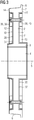
- a wheel brake disk 38 is connected, which comprises a first friction ring 39 and a second friction ring 40, which are screwed to a wheel body 1 of the wheel.
- a first protective shell 10 and a second protective shell 11 are screwed to the wheel body 1.
- protective enclosures are not shown.
- the first protective shell 10 is connected to a wheel web 2 of the wheel body 1 in the area of a first end face 12 of the wheel, the second protective shell 11 in the area of a second end face 13 of the wheel.
- the first protective shell 10 and the second protective shell 11 extend to Fig. 2 Starting from a center bore 4 of a wheel hub 3 of the wheel body 1, not up to a wheel rim 7 of the wheel, but only up to the wheel brake disc 38.
- the first protective shell 10 and the second protective shell 11 accordingly have a radial extension equal to an inner radius r of the wheel brake disc 38 on.
- the first protective shell 10 thus extends up to the first friction ring 39, the second protective shell 11 up to the second friction ring 40.
- the first protective shell 10 and the second protective shell 11 have a radial extension of less than the inner radius r of the wheel brake disc 38.
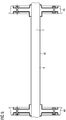
- Fig. 3 discloses a side elevation of an exemplary third embodiment variant of a wheel according to the invention of a chassis of a rail vehicle in a sectional illustration.
- FIG. 3 This third variant is similar to that exemplary second variant of a wheel according to the invention, which in connection with Fig. 2 is described. Therefore, in Fig. 3 in some cases the same reference numerals are used as in Fig. 2 .
- a wheel brake disk 38 which comprises a first friction ring 39 and a second friction ring 40, is screwed to a wheel body 1 of the wheel.
- a first protective shell 10 and a second protective shell 11 are also connected to the wheel body 1.
- the first protective shell 10 and the second protective shell 11 are according to FIG Fig. 3 clamped between the wheel body 1 and the wheel brake disk 38.
- the first protective shell 10 and the second protective shell 11 are arranged to run along a wheel web 2 of the wheel body 1 and extend from a central bore 4 of a wheel hub 3 of the wheel body 1 to a first end face 14 and a second end face 15 of a wheel rim 7 of the wheel body 1 .
- the first protective shell 10 extends up to the first end face 14, and the second protective shell 11 extends up to the second end face 15.
- the first protective shell 10 has an outer first shell part 34 made of metal and an inner second shell part 35 made of elastomer, the second shell part 35 being arranged facing the wheel body 1.
- the second protective shell 11 has an outer third shell part 36 made of metal and an inner fourth shell part 37 made of elastomer, the fourth shell part 37 being arranged facing the wheel body 1.
- Fig. 4 a floor plan of an exemplary fourth embodiment variant of a wheel according to the invention of a chassis of a rail vehicle with a first protective shell 10 is shown.
- the first protective shell 10 comprises a first protective shell element 41, a second protective shell element 42 and a third protective shell element 43, which are formed individually, that is to say separated from one another.
- the first protective shell element 41, the second protective shell element 42 and the third protective shell element 43 are arranged adjacent to one another and are designed in the shape of a circular sector in plan. According to the invention, however, it is also conceivable that the first protective shell element 41, the second protective shell element 42 and the third protective shell element 43 are arranged so as to overlap one another.
- the first protective shell element 41, the second protective shell element 42 and the third protective shell element 43 are attached to a first end face 12 of a wheel body 1 of the wheel by means of a first through screw 16, a second through screw 17 and further through screws which are passed through the wheel body 1 and on one through a pitch circle radius r L defined circumference are arranged, screwed to a wheel web 2 of the wheel body 1 of the wheel.
- the first protective shell element 41, the second protective shell element 42 and the third protective shell element 43 can thus be exchanged independently of one another.
- the first protective shell element 41, the second protective shell element 42 and the third protective shell element 43 extend from a central bore 4 of a wheel hub 3 of the wheel body 1 to a first end face 14 of a wheel rim 7 of the wheel body 1 and are arranged adjacent to the wheel body 1, following its contour. According to the invention, however, it is also conceivable that the first protective shell element 41, the second protective shell element 42 and the third protective shell element 43 are arranged at a distance from the wheel body 1 (for example by means of spacers or by means of screw spacers between the first protective shell element 41, the second protective shell element 42 and the third protective shell element 43 on the one hand and the wheel body 1 on the other hand).
- the wheel rim 7 has a wheel rim 8.
- a running surface 9 is provided on the circumference of the wheel body 1.
- a central angle ⁇ of the first protective shell element 41, the second protective shell element 42 and the third protective shell element 43 is 120 °.
- a number of protective shell elements, which are formed as the quotient of a double number of circles 2 ⁇ and the central angle ⁇ in radians, are arranged on the first end face 12 of the wheel body 1.
- Fig. 4 illustrated fourth embodiment of a wheel according to the invention three.
- a first protective shim 22 is connected to the first through screw 16
- a second protective shim 23 is connected to the second through screw 17, and further protective shims are connected to the other through bolts.
- the first protective insert 22, the second protective insert 23 and the other protective inserts which are structurally the same as, for example, in that exemplary first embodiment variant of a wheel according to the invention that is used in connection with Fig. 1 is described, are executed, are arranged adjacent to the first protective shell element 41, the second protective shell element 42 and the third protective shell element 43.
- the first protective shell element 41, the second protective shell element 42 and the third protective shell element 43 each have an outer shell part made of composite sheet metal and, facing the wheel body 1, an inner shell part made of elastomer.
- Fig. 5 shows a side elevation of an exemplary embodiment variant of a wheelset in a sectional illustration with a first wheel 44 according to the invention, a second wheel 45 according to the invention and a wheelset shaft 6 with a wheelset shaft protective jacket 46.
- the first wheel 44 and the second wheel 45 have a common wheel axle 5 and are connected to the wheelset shaft 6 via press fits.
- the first wheel 44 and the second wheel 45 are similar to that exemplary first embodiment variant of a wheel according to the invention, which in connection with Fig. 1 is described, executed and have corresponding protective shells.
- the wheelset shaft protective jacket 46 is looped around the wheelset shaft 6 and comprises a flexible elastomer mat which contacts the wheelset shaft 6 and a flexible sheet metal housing which surrounds the elastomer mat.
- the wheel set shaft protective jacket 46 is provided by means of in Fig. 5 hose clamps, which are not visible, are connected to the wheelset shaft 6.
- Protective shells arranged on the inner sides of the first wheel 44 and the second wheel 45 overlap the wheel set shaft protective casing 46 in the region of its ends.
Landscapes
- Engineering & Computer Science (AREA)
- Mechanical Engineering (AREA)
- Braking Arrangements (AREA)
- Tires In General (AREA)
Abstract
Description
- Die Erfindung betrifft ein Rad für Fahrzeuge, insbesondere für Fahrwerke von Schienenfahrzeugen, mit einem Radkörper und einer Lauffläche.
- Räder von Fahrzeugen, z.B. Schienenfahrzeugräder, sind insbesondere im Hochgeschwindigkeitsbetrieb häufig einem Aufprall von kleineren Objekten (z.B. von Steinen oder Schotter etc.) ausgesetzt, wodurch Schäden an den Rädern verursacht und Betriebseinschränkungen oder korrektive Wartungsmaßnahmen an den Fahrzeugen erforderlich werden können. Beispielsweise kann es dadurch erforderlich werden, ein Rad oder einen kompletten Radsatz vor Ablauf seiner geplanten Standzeit zu tauschen.
- Aus dem Stand der Technik ist beispielsweise die Radsatzwellenschutzanordnung Siemens Steel Rubber Axle Protection (SISRAP) bekannt. SISRAP schützt eine Radsatzwelle eines Schienenfahrzeugs z.B. vor Steinschlägen und umfasst eine tieftemperaturtaugliche Elastomermatte, Halbschalen aus nichtrostendem Stahlblech sowie Befestigungsbänder aus einem nichtrostenden Material.
Die Elastomermatte weist eine Dicke von 3mm auf und ummantelt eine Radsatzwelle, auf der eine Korrosionsschutzbeschichtung vorgesehen ist. Die Elastomermatte ist wiederum von zwei halbzylindrischen Halbschalen mit Dicken von je 2mm ummantelt. Querschnitte der beiden Halbschalen weisen gleiche Radien auf.
Die Radsatzwellenschutzanordnung SISRAP ist in derDE 10 2010 009 437 A1 offenbart. - Weiterhin zeigt die
WO 2018/166949 A1 eine ballistische Schutzanordnung für Fahrzeuge, bei welcher eine Radsatzwelle eines Fahrwerks eines Schienenfahrzeugs mittels einer Schale ummantelt ist. Die Schale weist mindestens eine Materialschicht aus mindestens einem Faserwerkstoff auf. - Die genannten Ansätze weisen in ihren bekannten Formen den Nachteil auf, dass die offenbarten Schutzanordnungen ausschließlich Radsatzwellen vor aufprallenden Objekten schützen.
- Der Erfindung liegt die Aufgabe zugrunde, ein gegenüber dem Stand der Technik weiterentwickeltes, vor aufprallenden Objekten geschütztes Rad anzugeben.
- Erfindungsgemäß wird diese Aufgabe gelöst mit einem Rad der eingangs genannten Art, bei dem zumindest eine erste Schutzschale mit dem Radkörper verbunden ist, wobei die zumindest erste Schutzschale mittels Schrauben, welche in Bohrungen des Radkörpers und der zumindest ersten Schutzschale gelagert sind, mit dem Radkörper verbunden ist, wobei mit den Schrauben Schutzbeilagen verbunden sind, welche Ausnehmungen aufweisen, in welchen Schraubenköpfe der Schrauben vorgesehen sind.
Durch diese Maßnahme können Objekte wie Steine oder Schotter etc. nicht unmittelbar auf gefährdete Bereiche des Radkörpers, wie z.B. auf einen Radsteg, aufprallen, sondern werden von der ersten Schutzschale abgefangen.
Dadurch werden Schäden an dem Rad vermieden und Risiken in Bezug auf einen vorzeitigen Räder- oder Radsatztausch gesenkt.
Das Rad kann einseitig (z.B. zu einer Außenseite des Fahrzeugs hin) oder beidseitig geschützt sein. Bei einem einseitigen Schutz ist auf einer ersten Stirnseite des Radkörpers die erste Schutzschale vorgesehen, auf einer zweiten Stirnseite des Radkörpers ist jedoch keine Schutzschale angeordnet.
Bei einem beidseitigen Schutz ist auf der ersten Stirnseite des Radkörpers die erste Schutzschale, auf der zweiten Stirnseite des Radkörpers eine zweite Schutzschale vorgesehen.
Darüber hinaus ist die erste Schutzschale einerseits aufgrund der Schrauben sicher mit dem Radkörper verbunden und andererseits sind, aufgrund der Ausnehmungen der Schutzbeilagen, in welchen die Schraubenköpfe der Schrauben vorgesehen sind, auch die Schrauben vor aufprallenden Objekten geschützt. - Es ist günstig, wenn die zumindest erste Schutzschale lösbar mit dem Radkörper verbunden ist.
Durch diese Maßnahme ist die erste Schutzschale tauschbar, wenn diese beispielsweise aufgrund von aufprallenden Objekten beschädigt wird. - Eine bevorzugte Lösung wird erreicht, wenn die zumindest erste Schutzschale entlang eines Radstegs verlaufend angeordnet ist.
In diesem Zusammenhang ist es auch hilfreich, wenn die zumindest erste Schutzschale sich bis zu einer Mittenbohrung einer Radnabe erstreckend angeordnet ist.
Ferner ist es günstig, wenn die zumindest erste Schutzschale sich bis zu einer ersten Stirnfläche eines Radkranzes erstreckend angeordnet ist.
Dadurch wird ein großer Teil des Radkörpers von der ersten Schutzschale abgedeckt. - Um auch ein Rad mit Radscheibenbremse vor aufprallenden Objekten zu schützen, ist es weiterhin vorteilhaft, wenn mit dem Radkörper eine Radbremsscheibe verbunden ist, wobei die zumindest erste Schutzschale eine radiale Erstreckung von kleiner oder gleich einem Innenradius der Radbremsscheibe aufweist.
- Es ist jedoch auch günstig, wenn mit dem Radkörper eine Radbremsscheibe verbunden ist, wobei die zumindest erste Schutzschale zwischen dem Radkörper und einem ersten Reibring der Radbremsscheibe eingespannt ist.
Durch diese Maßnahme können Befestigungsmittel der Radbremsscheibe und der erste Reibring selbst zur Verbindung der ersten Schutzschale mit dem Radkörper eingesetzt werden. - Eine günstige Ausgestaltung erhält man weiterhin, wenn die zumindest erste Schutzschale an den Radkörper anliegend angeordnet ist.
In diesem Zusammenhang ist es auch günstig, wenn die zumindest erste Schutzschale einem Konturverlauf des Radkörpers folgend ausgebildet ist.
Durch diese Maßnahme wird ein besonders kompaktes Rad mit Schutzanordnung erzielt. Ein Eindringen von Fremdkörpern in einen Bereich zwischen dem Radkörper und der ersten Schutzschale wird vermieden. Weiterhin ist ein Anliegen der ersten Schutzschale an den Radkörper auch aerodynamisch und akustisch günstig. - Aus Gründen einer einfachen Wartung und Instandhaltung ist es hilfreich, wenn die zumindest erste Schutzschale aus einzelnen Schutzschalenelementen ausgebildet ist.
Dadurch kann bei Beschädigung eines Schutzschalenelements dieses sehr rasch getauscht werden. Insbesondere dann, wenn das Rad Teil eines Radsatzes mit Radsatzlagern, Radsatzlagergehäusen etc. ist, können die einzelnen Schutzschalenelemente ohne Ausbau von Radsatzkomponenten demontiert und montiert werden.
Weiterhin braucht bei einer Mehrzahl an Schutzschalenelementen nur jenes von einem Schaden betroffene, im Verhältnis zu einer Gesamtfläche der ersten Schutzschale relativ kleine Schutzschalenelement getauscht werden, während unbeschädigte Schutzschalenelemente auf dem Radkörper montiert bleiben können. - Eine vorteilhafte Ausgestaltung erhält man, wenn die zumindest erste Schutzschale ein äußeres erstes Schalenteil aus Metall und ein inneres zweites Schalenteil aus Elastomer aufweist, wobei das zweite Schalenteil dem Radkörper zugewandt angeordnet ist.
Dadurch wird eine Funktionsaufteilung erreicht. Während das erste Schalenteil als robuste Abdeckung gegen auf die erste Schutzschale aufprallende Objekte fungiert, federt und dämpft das zweite Schalenteil, welches eine hohe Energieabsorptionsfähigkeit aufweist, Schläge gegen die erste Schutzschale. - Ein umfassender Schutz gegen Steinschläge, Schotterflug etc. wird mit einem Radsatz eines Fahrzeugs mit zwei je zumindest eine Schutzschale aufweisenden Rädern erreicht, wobei eine Radsatzwelle einen Radsatzwellenschutzmantel aufweist.
- Dabei ist es günstig, wenn Schutzschalen der Räder den Radsatzwellenschutzmantel überlappend angeordnet sind. Dadurch wird ein Korrosionsschutz in Übergangsbereichen zwischen der Radsatzwelle und den Rädern bewirkt.
- Nachfolgend wird die Erfindung anhand von Ausführungsbeispielen näher erläutert.
- Es zeigen beispielhaft:
- Fig. 1:
- Einen Seitenriss einer beispielhaften ersten Ausführungsvariante eines erfindungsgemäßen Rads in geschnittener Darstellung mit einer ersten Schutzschale und einer zweiten Schutzschale,
- Fig. 2:
- Einen Seitenriss einer beispielhaften zweiten Ausführungsvariante eines erfindungsgemäßen Rads in geschnittener Darstellung mit einer Radbremsscheibe sowie einer ersten Schutzschale und einer zweiten Schutzschale, welche sich bis zu der Radbremsscheibe erstrecken,
- Fig. 3:
- Einen Seitenriss einer beispielhaften dritten Ausführungsvariante eines erfindungsgemäßen Rads in geschnittener Darstellung mit einer Radbremsscheibe sowie einer ersten Schutzschale und einer zweiten Schutzschale, welche zwischen einem Radkörper und der Radbremsscheibe eingespannt sind,
- Fig. 4:
- Einen Grundriss einer beispielhaften vierten Ausführungsvariante eines erfindungsgemäßen Rads mit einer ersten Schutzschale, welche einzelne Schutzschalenelemente aufweist, und
- Fig. 5:
- Einen Seitenriss einer beispielhaften Ausführungsvariante eines Radsatzes in geschnittener Darstellung mit einem erfindungsgemäßen ersten Rad, einem erfindungsgemäßen zweiten Rad und einer Radsatzwelle mit einem Radsatzwellenschutzmantel.
-
Fig. 1 zeigt einen Seitenriss einer beispielhaften ersten Ausführungsvariante eines erfindungsgemäßen Rads für ein Fahrwerk eines Schienenfahrzeugs in geschnittener Darstellung.
Das Rad weist eine einen Radkörper 1 mit einem Radsteg 2 und einer Radnabe 3 auf. Die Radnabe 3 weist wiederum eine Mittenbohrung 4 mit einer Radachse 5 auf. Über die Mittenbohrung 4 ist eine beispielhaft inFig. 5 dargestellte Radsatzwelle 6 mit dem Rad verbindbar.
Der Radkörper 1 umfasst weiterhin einen Radkranz 7 mit einem Spurkranz 8. An dem Rad ist weiterhin umfangsseitig eine Lauffläche 9 vorgesehen, über welche das Rad auf einer inFig. 1 nicht gezeigten Schiene abrollen kann. - Das Rad weist eine erste Schutzschale 10 und eine zweite Schutzschale 11 auf, welche mit dem Radkörper 1 verschraubt und somit lösbar verbunden sind. Die erste Schutzschale 10 ist auf einer ersten Stirnseite 12 des Radkörpers 1 vorgesehen, die zweite Schutzschale 11 auf einer zweiten Stirnseite 13 des Radkörpers 1.
Die erste Schutzschale 10 und die zweite Schutzschale 11 sind entlang des Radstegs 2 verlaufend sowie sich einerseits bis zu der Mittenbohrung 4 der Radnabe 3 und andererseits bis zu Stirnflächen des Radkranzes 7 erstreckend angeordnet.
Die erste Schutzschale 10 ist dabei sich bis zu einer ersten Stirnfläche 14 des Radkranzes 7 erstreckend vorgesehen, die zweite Schutzschale 11 sich bis zu einer zweiten Stirnfläche 15 des Radkranzes 7 erstreckend.
Die erste Schutzschale 10 und die zweite Schutzschale 11 sind an den Radkörper 1 anliegend angeordnet und Konturverläufen des Radkörpers 1 folgend ausgebildet.
Erfindungsgemäß ist es jedoch auch denkbar, dass die erste Schutzschale 10 und die zweite Schutzschale 11 von dem Radkörper 1 beabstandet angeordnet sind (beispielsweise mittels Distanzstücken oder mittels Schrauben-Distanzscheiben zwischen der ersten Schutzschale 10 und der zweiten Schutzschale 11 einerseits und dem Radkörper 1 andererseits). - Das Rad gemäß
Fig. 1 ist vereinfachend kantig dargestellt. Erfindungsgemäß ist es jedoch selbstverständlich möglich und üblicherweise vorgesehen, dass das Rad gerundete Konturen mit unterschiedlichen Radien aufweist (z.B. an Übergängen zwischen der Radnabe 3 und dem Radsteg 2, zwischen dem Radsteg 2 und dem Radkranz 7 etc.). Die erste Schutzschale 10 und die zweite Schutzschale 11 sind dabei diesen gerundeten Konturen folgend und an den Radkörper 1 anliegend angeordnet. - Die erste Schutzschale 10 und die zweite Schutzschale 11 sind im Grundriss kreisringförmig ausgebildet.
Die erste Schutzschale 10 und die zweite Schutzschale 11 sind mittels Durchgangsschrauben, welche durch Bohrungen in dem Radkörper 1 sowie in der ersten Schutzschale 10 und in der zweiten Schutzschale 11 hindurchgeführt sind, und Schraubenmuttern mit dem Radkörper 1 verspannt.
Von diesen Durchgangsschrauben und Schraubenmuttern sind inFig. 1 eine erste Durchgangsschraube 16, welche mit einer ersten Schraubenmutter 18 verbunden ist, sowie eine zweite Durchgangsschraube 17, welche mit einer zweiten Schraubenmutter 19 verbunden ist, sichtbar. Die erste Durchgangsschraube 16 ist durch eine erste Bohrung 20 in dem Radkörper 1, die zweite Durchgangsschraube 17 durch eine zweite Bohrung 21 in dem Radkörper 1 hindurchgeführt.
Die erste Bohrung 20 und die zweite Bohrung 21 sind deckungsgleich mit Bohrungen in der ersten Schutzschale 10 und in der zweiten Schutzschale 11 angeordnet. Erfindungsgemäß ist es jedoch auch vorstellbar, die erste Schutzschale 10 und die zweite Schutzschale 11 über geeignete Klemmmittel beispielsweise mit der Radnabe 3 zu verklemmen. - Mit der ersten Durchgangsschraube 16 ist im Bereich der ersten Stirnseite 12 des Radkörpers 1 eine zylindrische erste Schutzbeilage 22 verbunden, im Bereich der zweiten Stirnseite 13 eine zylindrische zweite Schutzbeilage 23. Die erste Schutzbeilage 22 und die zweite Schutzbeilage 23 sind in einem Elastomer ausgeführt.
Die erste Schutzbeilage 22 weist eine zylindrische erste Ausnehmung 26 auf, in welcher die erste Schraubenmutter 18 vorgesehen ist. Die zweite Schutzbeilage 23 umfasst eine zylindrische zweite Ausnehmung 27, in welcher ein erster Schraubenkopf 30 der ersten Durchgangsschraube 16 angeordnet ist.
Mit der zweiten Durchgangsschraube 17 ist im Bereich der ersten Stirnseite 12 des Radkörpers 1 eine zylindrische dritte Schutzbeilage 24 verbunden, im Bereich der zweiten Stirnseite 13 eine zylindrische vierte Schutzbeilage 25. Die dritte Schutzbeilage 24 und die vierte Schutzbeilage 25 sind in einem Elastomer ausgebildet.
Die dritte Schutzbeilage 24 weist eine zylindrische dritte Ausnehmung 28 auf, in welcher die zweite Schraubenmutter 19 vorgesehen ist. Die vierte Schutzbeilage 25 umfasst eine zylindrische vierte Ausnehmung 29, in welcher ein zweiter Schraubenkopf 31 der zweiten Durchgangsschraube 17 angeordnet ist. - Die erste Durchgangsschraube 16, die erste Schraubenmutter 18, die erste Bohrung 20 und die erste Schutzbeilage 22 weisen in jenem in
Fig. 1 dargestellten Montagezustand eine gemeinsame erste Längsachse 32 auf; die zweite Durchgangsschraube 17, die zweite Schraubenmutter 19, die zweite Bohrung 21 und die zweite Schutzbeilage 23 eine gemeinsame zweite Längsachse 33.
Die erste Längsachse 32 und die zweite Längsachse 33 sind parallel zu der Radachse 5 ausgerichtet.
Die erste Schutzbeilage 22 und die zweite Schutzbeilage 23 weisen im Bereich ihrer Grundflächen Bohrungen auf, durch welche die erste Durchgangsschraube 16 hindurchgeführt ist. Die erste Schraubenmutter 18 und der erste Schraubenkopf 30 liegen im Bereich der Grundflächen der ersten Schutzbeilage 22 und der zweiten Schutzbeilage 23 an der ersten Schutzbeilage 22 bzw. an der zweiten Schutzbeilage 23 an. - Die dritte Schutzbeilage 24 und die vierte Schutzbeilage 25 weisen im Bereich ihrer Grundflächen Bohrungen auf, durch welche die zweite Durchgangsschraube 17 hindurchgeführt ist. Die zweite Schraubenmutter 19 und der zweite Schraubenkopf 31 liegen im Bereich der Grundflächen der dritten Schutzbeilage 24 und der vierten Schutzbeilage 25 an der dritten Schutzbeilage 24 bzw. an der vierten Schutzbeilage 25 an. Die erste Schutzbeilage 22 und die dritte Schutzbeilage 24 liegen an der ersten Schutzschale 10 an, die zweite Schutzbeilage 23 und die vierte Schutzbeilage 25 an der zweiten Schutzschale 11.
- Die erste Schutzschale 10 weist ein äußeres erstes Schalenteil 34 aus Verbundblech, d.h. aus Metall, und ein inneres zweites Schalenteil 35 aus einem biegsamen Elastomer auf, wobei das zweite Schalenteil 35 dem Radkörper 1 zugewandt angeordnet ist.
Die zweite Schutzschale 11 weist ein äußeres drittes Schalenteil 36 aus Verbundblech und ein inneres viertes Schalenteil 37 aus einem biegsamen Elastomer auf, wobei das vierte Schalenteil 37 dem Radkörper 1 zugewandt angeordnet ist.
Erfindungsgemäß ist es jedoch auch denkbar, dass die erste Schutzschale 10 und die zweite Schutzschale 11 aus faserverstärktem Kunststoff mit einer Matrix aus organischem Material sowie einem ersten Faserwerkstoff (beispielsweise aus Polyethylen-Fasern) und einem zweiten Faserwerkstoff (beispielsweise aus Glasfasern) ausgebildet sind. - In
Fig. 2 ist eine beispielhafte zweiten Ausführungsvariante eines erfindungsgemäßen Rads eines Fahrwerks eines Schienenfahrzeugs in geschnittener Darstellung dargestellt. Diese beispielhafte zweite Ausführungsvariante ähnelt jener beispielhaften ersten Ausführungsvariante eines erfindungsgemäßen Rads, die inFig. 1 gezeigt ist. Es werden daher inFig. 2 teilweise gleiche Bezugszeichen verwendet wie inFig. 1 . - Im Unterschied zu jener beispielhaften ersten Ausführungsvariante eines erfindungsgemäßen Rads, welche in
Fig. 1 gezeigt ist, ist mit dem Rad gemäßFig. 2 eine Radbremsscheibe 38 verbunden, die einen ersten Reibring 39 und einen zweiten Reibring 40 umfasst, welche mit einem Radkörper 1 des Rads verschraubt sind.
Weiterhin sind mit dem Radkörper 1 eine erste Schutzschale 10 und eine zweite Schutzschale 11 verschraubt. Im Unterschied zuFig. 1 sind inFig. 2 jedoch keine Schutzbeilagen dargestellt.
Die erste Schutzschale 10 ist im Bereich einer ersten Stirnseite 12 des Rads mit einem Radsteg 2 des Radkörpers 1 verbunden, die zweite Schutzschale 11 im Bereich einer zweiten Stirnseite 13 des Rads. - Im Unterschied zu der beispielhaften ersten Ausführungsvariante eines erfindungsgemäßen Rads gemäß
Fig. 1 , erstrecken sich die erste Schutzschale 10 und die zweite Schutzschale 11 nachFig. 2 ausgehend von einer Mittenbohrung 4 einer Radnabe 3 des Radkörpers 1 nicht bis zu einem Radkranz 7 des Rads, sondern lediglich bis zu der Radbremsscheibe 38. Die erste Schutzschale 10 und die zweite Schutzschale 11 weisen demnach eine radiale Erstreckung von gleich einem Innenradius r der Radbremsscheibe 38 auf.
Die erste Schutzschale 10 erstreckt sich also bis zu dem ersten Reibring 39, die zweite Schutzschale 11 bis zu dem zweiten Reibring 40.
Erfindungsgemäß ist es jedoch auch vorstellbar, dass die erste Schutzschale 10 und die zweite Schutzschale 11 eine radiale Erstreckung von kleiner dem Innenradius r der Radbremsscheibe 38 aufweisen. -
Fig. 3 offenbart einen Seitenriss einer beispielhaften dritten Ausführungsvariante eines erfindungsgemäßen Rads eines Fahrwerks eines Schienenfahrzeugs in geschnittener Darstellung. - Diese dritte Ausführungsvariante ähnelt jener beispielhaften zweiten Ausführungsvariante eines erfindungsgemäßen Rads, welche im Zusammenhang mit
Fig. 2 beschrieben ist.
Es werden daher inFig. 3 teilweise gleiche Bezugszeichen verwendet wie inFig. 2 .
Mit einem Radkörper 1 des Rads ist eine Radbremsscheibe 38 verschraubt, welche einen ersten Reibring 39 und einen zweiten Reibring 40 umfasst.
Mit dem Radkörper 1 sind weiterhin eine erste Schutzschale 10 und eine zweite Schutzschale 11 verbunden.
Im Unterschied zu jener beispielhaften zweiten Ausführungsvariante eines erfindungsgemäßen Rads, welche inFig. 2 gezeigt ist, sind die erste Schutzschale 10 und die zweite Schutzschale 11 gemäßFig. 3 zwischen dem Radkörper 1 und der Radbremsscheibe 38 eingespannt.
Es sind daher zur Verbindung der ersten Schutzschale 10 und der zweiten Schutzschale 11 mit dem Radkörper 1 keine eigenen Durchgangsschrauben, welche z.B. inFig. 2 gezeigt sind, erforderlich, es sind vielmehr Befestigungsmittel der Radbremsscheibe 38 bzw. die Radbremsscheibe 38 selbst zum Verspannen der ersten Schutzschale 10 und der zweiten Schutzschale 11 eingesetzt. - Die erste Schutzschale 10 und die zweite Schutzschale 11 sind entlang eines Radstegs 2 des Radkörpers 1 verlaufend angeordnet und erstrecken sich ausgehend von einer Mittenbohrung 4 einer Radnabe 3 des Radkörpers 1 bis zu einer ersten Stirnfläche 14 und einer zweiten Stirnfläche 15 eines Radkranzes 7 des Radkörpers 1.
Die erste Schutzschale 10 erstreckt sich bis zu der ersten Stirnfläche 14, die zweite Schutzschale 11 bis zu der zweiten Stirnfläche 15.
Die erste Schutzschale 10 weist ein äußeres erstes Schalenteil 34 aus Metall und ein inneres zweites Schalenteil 35 aus Elastomer auf, wobei das zweite Schalenteil 35 dem Radkörper 1 zugewandt angeordnet ist. - Die zweite Schutzschale 11 weist ein äußeres drittes Schalenteil 36 aus Metall und ein inneres viertes Schalenteil 37 aus Elastomer auf, wobei das vierte Schalenteil 37 dem Radkörper 1 zugewandt angeordnet ist.
- In
Fig. 4 ist ein Grundriss einer beispielhaften vierten Ausführungsvariante eines erfindungsgemäßen Rads eines Fahrwerks eines Schienenfahrzeugs mit einer ersten Schutzschale 10 dargestellt.
Die erste Schutzschale 10 umfasst ein erstes Schutzschalenelement 41, ein zweites Schutzschalenelement 42 sowie ein drittes Schutzschalenelement 43, welche einzeln, d.h. voneinander getrennt, ausgebildet sind.
Das erste Schutzschalenelement 41, das zweite Schutzschalenelement 42 und das dritte Schutzschalenelement 43 sind aneinander angrenzend angeordnet und im Grundriss kreisringsektorförmig ausgebildet.
Erfindungsgemäß ist es jedoch auch vorstellbar, dass das erste Schutzschalenelement 41, das zweite Schutzschalenelement 42 und das dritte Schutzschalenelement 43 einander überlappend angeordnet sind. - Das erste Schutzschalenelement 41, das zweite Schutzschalenelement 42 und das dritte Schutzschalenelement 43 sind an einer ersten Stirnseite 12 eines Radkörpers 1 des Rads mittels einer ersten Durchgangsschraube 16, einer zweiten Durchgangsschraube 17 sowie weiteren Durchgangsschrauben, welche durch den Radkörper 1 hindurchgeführt sind und auf einem durch einen Lochkreisradius rL definierten Umfang angeordnet sind, mit einem Radsteg 2 des Radkörpers 1 des Rads verschraubt.
Das erste Schutzschalenelement 41, das zweite Schutzschalenelement 42 und das dritte Schutzschalenelement 43 sind somit unabhängig voneinander tauschbar. - Das erste Schutzschalenelement 41, das zweite Schutzschalenelement 42 und das dritte Schutzschalenelement 43 erstrecken sich von einer Mittenbohrung 4 einer Radnabe 3 des Radkörpers 1 bis zu einer ersten Stirnfläche 14 eines Radkranzes 7 des Radkörpers 1 und sind an den Radkörper 1 anliegend, dessen Konturverlauf folgend, angeordnet. Erfindungsgemäß ist es jedoch auch denkbar, dass das erste Schutzschalenelement 41, das zweite Schutzschalenelement 42 und das dritte Schutzschalenelement 43 von dem Radkörper 1 beabstandet angeordnet sind (beispielsweise mittels Distanzstücken oder mittels Schrauben-Distanzscheiben zwischen dem ersten Schutzschalenelement 41, dem zweiten Schutzschalenelement 42 und dem dritten Schutzschalenelement 43 einerseits und dem Radkörper 1 andererseits).
- Der Radkranz 7 weist einen Spurkranz 8 auf.
Auf dem Radkörper 1 ist umfangsseitig eine Lauffläche 9 vorgesehen.
Ein Mittelpunktswinkel θ des ersten Schutzschalenelements 41, des zweiten Schutzschalenelements 42 und des dritten Schutzschalenelements 43 beträgt 120°.
An der ersten Stirnseite 12 des Radkörpers 1 ist eine Anzahl an Schutzschalenelementen, welche als Quotient aus einer doppelten Kreiszahl 2π und dem Mittelpunktswinkel θ im Bogenmaß gebildet ist, angeordnet. Diese Anzahl beträgt für die inFig. 4 dargestellte vierte Ausführungsvariante eines erfindungsgemäßen Rads drei. - Mit der ersten Durchgangsschraube 16 ist eine erste Schutzbeilage 22, mit der zweiten Durchgangsschraube 17 eine zweite Schutzbeilage 23, mit den weiteren Durchgangsschrauben sind weitere Schutzbeilagen verbunden.
Die erste Schutzbeilage 22, die zweite Schutzbeilage 23 und die weiteren Schutzbeilagen, welche konstruktiv gleich wie z.B. in jener beispielhaften ersten Ausführungsvariante eines erfindungsgemäßen Rads, die im Zusammenhang mitFig. 1 beschrieben ist, ausgeführt sind, sind an das erste Schutzschalenelement 41, das zweite Schutzschalenelement 42 und das dritte Schutzschalenelement 43 anliegend angeordnet. - Das erste Schutzschalenelement 41, das zweite Schutzschalenelement 42 und das dritte Schutzschalenelement 43 weisen jeweils ein äußeres Schalenteil aus Verbundblech sowie, dem Radkörper 1 zugewandt, ein inneres Schalenteil aus Elastomer auf.
-
Fig. 5 zeigt einen Seitenriss einer beispielhaften Ausführungsvariante eines Radsatzes in geschnittener Darstellung mit einem erfindungsgemäßen ersten Rad 44, einem erfindungsgemäßen zweiten Rad 45 und einer Radsatzwelle 6 mit einem Radsatzwellenschutzmantel 46.
Das erste Rad 44 und das zweite Rad 45 weisen eine gemeinsame Radachse 5 auf und sind über Presssitze mit der Radsatzwelle 6 verbunden.
Das erste Rad 44 und das zweite Rad 45 sind ähnlich jener beispielhaften ersten Ausführungsvariante eines erfindungsgemäßen Rads, welche im Zusammenhang mitFig. 1 beschrieben ist, ausgeführt und weisen entsprechende Schutzschalen auf.
Der Radsatzwellenschutzmantel 46 ist um die Radsatzwelle 6 geschlungen und umfasst eine biegsame Elastomermatte, welche die Radsatzwelle 6 kontaktiert, sowie ein biegsames Blechgehäuse, welches die Elastomermatte ummantelt.
Der Radsatzwellenschutzmantel 46 ist mittels inFig. 5 nicht sichtbarer Schlauchschellen mit der Radsatzwelle 6 verbunden. An Innenseiten des ersten Rads 44 und des zweiten Rads 45 angeordnete Schutzschalen überlappen den Radsatzwellenschutzmantel 46 im Bereich von dessen Enden. -
- 1
- Radkörper
- 2
- Radsteg
- 3
- Radnabe
- 4
- Mittenbohrung
- 5
- Radachse
- 6
- Radsatzwelle
- 7
- Radkranz
- 8
- Spurkranz
- 9
- Lauffläche
- 10
- Erste Schutzschale
- 11
- Zweite Schutzschale
- 12
- Erste Stirnseite
- 13
- Zweite Stirnseite
- 14
- Erste Stirnfläche
- 15
- Zweite Stirnfläche
- 16
- Erste Durchgangsschraube
- 17
- Zweite Durchgangsschraube
- 18
- Erste Schraubenmutter
- 19
- Zweite Schraubenmutter
- 20
- Erste Bohrung
- 21
- Zweite Bohrung
- 22
- Erste Schutzbeilage
- 23
- Zweite Schutzbeilage
- 24
- Dritte Schutzbeilage
- 25
- Vierte Schutzbeilage
- 26
- Erste Ausnehmung
- 27
- Zweite Ausnehmung
- 28
- Dritte Ausnehmung
- 29
- Vierte Ausnehmung
- 30
- Erster Schraubenkopf
- 31
- Zweiter Schraubenkopf
- 32
- Erste Längsachse
- 33
- Zweite Längsachse
- 34
- Erstes Schalenteil
- 35
- Zweites Schalenteil
- 36
- Drittes Schalenteil
- 37
- Viertes Schalenteil
- 38
- Radbremsscheibe
- 39
- Erster Reibring
- 40
- Zweiter Reibring
- 41
- Erstes Schutzschalenelement
- 42
- Zweites Schutzschalenelement
- 43
- Drittes Schutzschalenelement
- 44
- Erstes Rad
- 45
- Zweites Rad
- 46
- Radsatzwellenschutzmantel
- r
- Innenradius
- rL
- Lochkreisradius
- θ
- Mittelpunktswinkel
Claims (18)
- Rad für Fahrzeuge, insbesondere für Fahrwerke von Schienenfahrzeugen, mit einem Radkörper und einer Lauffläche, dadurch gekennzeichnet, dass zumindest eine erste Schutzschale (10) mit dem Radkörper (1) verbunden ist, wobei die zumindest erste Schutzschale (10) mittels Schrauben, welche in Bohrungen des Radkörpers (1) und der zumindest ersten Schutzschale (10) gelagert sind, mit dem Radkörper (1) verbunden ist, wobei mit den Schrauben Schutzbeilagen verbunden sind, welche Ausnehmungen aufweisen, in welchen Schraubenköpfe der Schrauben vorgesehen sind.
- Rad nach Anspruch 1, dadurch gekennzeichnet, dass die zumindest erste Schutzschale (10) lösbar mit dem Radkörper (1) verbunden ist.
- Rad nach Anspruch 1 oder 2, dadurch gekennzeichnet, dass die zumindest erste Schutzschale (10) entlang eines Radstegs (2) verlaufend angeordnet ist.
- Rad nach Anspruch 3, dadurch gekennzeichnet, dass die zumindest erste Schutzschale (10) sich bis zu einer Mittenbohrung (4) einer Radnabe (3) erstreckend angeordnet ist.
- Rad nach Anspruch 3 oder 4, dadurch gekennzeichnet, dass die zumindest erste Schutzschale (10) sich bis zu einer ersten Stirnfläche (14) eines Radkranzes (7) erstreckend angeordnet ist.
- Rad nach einem der Ansprüche 1 bis 4, dadurch gekennzeichnet, dass mit dem Radkörper (1) eine Radbremsscheibe (38) verbunden ist, wobei die zumindest erste Schutzschale (10) eine radiale Erstreckung von kleiner oder gleich einem Innenradius (r) der Radbremsscheibe (38) aufweist.
- Rad nach einem der Ansprüche 1 bis 5, dadurch gekennzeichnet, dass mit dem Radkörper (1) eine Radbremsscheibe (38) verbunden ist, wobei die zumindest erste Schutzschale (10) zwischen dem Radkörper (1) und einem ersten Reibring (39) der Radbremsscheibe (38) eingespannt ist.
- Rad nach einem der Ansprüche 1 bis 7, dadurch gekennzeichnet, dass die zumindest erste Schutzschale (10) an den Radkörper (1) anliegend angeordnet ist.
- Rad nach einem der Ansprüche 1 bis 7, dadurch gekennzeichnet, dass die zumindest erste Schutzschale (10) von dem Radkörper (1) beabstandet angeordnet ist.
- Rad nach einem der Ansprüche 1 bis 9, dadurch gekennzeichnet, dass die zumindest erste Schutzschale (10) einem Konturverlauf des Radkörpers (1) folgend ausgebildet ist.
- Rad nach einem der Ansprüche 1 bis 10, dadurch gekennzeichnet, dass die zumindest erste Schutzschale (10) im Grundriss kreisringförmig ausgebildet ist.
- Rad nach einem der Ansprüche 1 bis 11, dadurch gekennzeichnet, dass die zumindest erste Schutzschale (10) aus einzelnen Schutzschalenelementen ausgebildet ist.
- Rad nach Anspruch 12, dadurch gekennzeichnet, dass die einzelnen Schutzschalenelemente aneinander angrenzend angeordnet sind.
- Rad nach Anspruch 12, dadurch gekennzeichnet, dass die einzelnen Schutzschalenelemente einander überlappend angeordnet sind.
- Rad nach einem der Ansprüche 1 bis 14, dadurch gekennzeichnet, dass die zumindest erste Schutzschale (10) ein äußeres erstes Schalenteil (34) aus Metall und ein inneres zweites Schalenteil (35) aus Elastomer aufweist, wobei das zweite Schalenteil (35) dem Radkörper (1) zugewandt angeordnet ist.
- Rad nach einem der Ansprüche 1 bis 14, dadurch gekennzeichnet, dass die zumindest erste Schutzschale (10) aus faserverstärktem Kunststoff mit einer Matrix aus organischem Material sowie einem ersten Faserwerkstoff und einem zweiten Faserwerkstoff ausgebildet ist.
- Radsatz eines Fahrzeugs mit zwei Rädern nach einem der Ansprüche 1 bis 16, dadurch gekennzeichnet, dass eine Radsatzwelle (6) einen Radsatzwellenschutzmantel (46) aufweist.
- Radsatz nach Anspruch 17, dadurch gekennzeichnet, dass Schutzschalen der Räder den Radsatzwellenschutzmantel (46) überlappend angeordnet sind.
Applications Claiming Priority (1)
| Application Number | Priority Date | Filing Date | Title |
|---|---|---|---|
| ATA50212/2020A AT523425B1 (de) | 2020-03-12 | 2020-03-12 | Rad für Fahrzeuge |
Publications (1)
| Publication Number | Publication Date |
|---|---|
| EP3878662A1 true EP3878662A1 (de) | 2021-09-15 |
Family
ID=74870738
Family Applications (1)
| Application Number | Title | Priority Date | Filing Date |
|---|---|---|---|
| EP21161816.0A Withdrawn EP3878662A1 (de) | 2020-03-12 | 2021-03-10 | Rad für fahrzeuge |
Country Status (2)
| Country | Link |
|---|---|
| EP (1) | EP3878662A1 (de) |
| AT (1) | AT523425B1 (de) |
Citations (5)
| Publication number | Priority date | Publication date | Assignee | Title |
|---|---|---|---|---|
| US2643152A (en) * | 1950-10-05 | 1953-06-23 | Fairbanks Morse & Co | Sound deadening means for car wheels |
| DE102010009437A1 (de) | 2010-02-22 | 2011-08-25 | Siemens Aktiengesellschaft, 80333 | Radsatzwellenschutz |
| KR20120001962U (ko) * | 2010-09-08 | 2012-03-16 | 주식회사 에이브이티 | 방음 차륜 |
| DE102010053218A1 (de) * | 2010-12-03 | 2012-06-06 | Bochumer Verein Verkehrstechnik Gmbh | Schienenrad |
| WO2018166949A1 (de) | 2017-03-14 | 2018-09-20 | Siemens Ag Österreich | Ballistische schutzanordnung für fahrzeuge |
Family Cites Families (7)
| Publication number | Priority date | Publication date | Assignee | Title |
|---|---|---|---|---|
| JPS6110140A (ja) * | 1984-06-22 | 1986-01-17 | Orion Mach Co Ltd | 回転部品等における騒音防止方法 |
| EP0872358A1 (de) * | 1997-04-16 | 1998-10-21 | Alusuisse Technology & Management AG | Schienenfahrzeugrad |
| CN100413712C (zh) * | 2003-09-30 | 2008-08-27 | 尹学军 | 车轮 |
| DE202006012852U1 (de) * | 2006-08-22 | 2006-10-26 | Gutehoffnungshütte Radsatz Gmbh | Schallabsorber-Element und Schallabsorber für ein Schienenfahrzeug-Rad sowie damit ausgestattetes Rad |
| DE102009037936A1 (de) * | 2009-08-19 | 2011-02-24 | Poroson Gmbh | Rad für ein Schienenfahrzeug |
| EP2332802A1 (de) * | 2009-12-10 | 2011-06-15 | Jochen Zingelmann | Absorptionsvorrichtung auf schwingenden Oberflächen, insbesondere bei Schienenfahrzeugen und Schienenstrecken |
| HUE060114T2 (hu) * | 2014-06-26 | 2023-01-28 | Bombardier Transp Gmbh | Futómû csökkentett torziós lengéssel |
-
2020
- 2020-03-12 AT ATA50212/2020A patent/AT523425B1/de not_active IP Right Cessation
-
2021
- 2021-03-10 EP EP21161816.0A patent/EP3878662A1/de not_active Withdrawn
Patent Citations (5)
| Publication number | Priority date | Publication date | Assignee | Title |
|---|---|---|---|---|
| US2643152A (en) * | 1950-10-05 | 1953-06-23 | Fairbanks Morse & Co | Sound deadening means for car wheels |
| DE102010009437A1 (de) | 2010-02-22 | 2011-08-25 | Siemens Aktiengesellschaft, 80333 | Radsatzwellenschutz |
| KR20120001962U (ko) * | 2010-09-08 | 2012-03-16 | 주식회사 에이브이티 | 방음 차륜 |
| DE102010053218A1 (de) * | 2010-12-03 | 2012-06-06 | Bochumer Verein Verkehrstechnik Gmbh | Schienenrad |
| WO2018166949A1 (de) | 2017-03-14 | 2018-09-20 | Siemens Ag Österreich | Ballistische schutzanordnung für fahrzeuge |
Also Published As
| Publication number | Publication date |
|---|---|
| AT523425B1 (de) | 2021-08-15 |
| AT523425A4 (de) | 2021-08-15 |
Similar Documents
| Publication | Publication Date | Title |
|---|---|---|
| EP2663769B1 (de) | Anordnung von bauteilen einer windenergieanlage | |
| DE2931400C2 (de) | Nutzfahrzeugrad für Einzel- und Zwillingsanordnung | |
| EP3573844B1 (de) | Rad für schienenfahrzeuge | |
| EP1891302A1 (de) | Scheibenanordnung für einen turbolader | |
| DE102012105549A1 (de) | Planetengetriebe hohlradaufhängung | |
| EP3554917B1 (de) | Ballistische schutzanordnung für fahrzeuge | |
| DE19639304B4 (de) | Elastische Gelenkkupplung | |
| EP1272386B1 (de) | Rad für ein kettenfahrzeug | |
| AT523425B1 (de) | Rad für Fahrzeuge | |
| DE102016211203A1 (de) | Lauftrommelanordnung für einen Reifenprüfstand sowie Reifenprüfstand mit der Lauftrommelanordnung | |
| AT390591B (de) | Vorrichtung zur elastischen anordnung von auf angetriebenen oder getriebenen radnaben befestigten raedern | |
| DE102017130290B4 (de) | Bremsscheibe | |
| EP1916432B1 (de) | Wellenverbindung und Unterlegprofil für eine solche | |
| EP3789186B1 (de) | Ultraschallbearbeitungsvorrichtung | |
| DE102016002436B4 (de) | Baumaschine mit einer Vorrichtung zum Entkoppeln eines Hydraulikmotors | |
| EP3666544A1 (de) | Radsatz für ein schienenfahrzeug | |
| EP3686076A1 (de) | Getriebegehäuse und anordnung zur abstützung eines getriebes | |
| DE19812527C2 (de) | Ausgleichkupplung | |
| EP0534899A1 (de) | Antrieb für einen Radsatz eines Schienentriebfahrzeuges und Federelement für einen derartigen Antrieb | |
| DE1836832U (de) | Bremsscheibe, insbesondere fuer schienenfahrzeuge. | |
| EP0081640A1 (de) | Doppelachsantrieb für Schienentriebfahrzeuge | |
| EP1995487B1 (de) | Bremsscheibe | |
| DE3435872C2 (de) | ||
| EP3685066A1 (de) | Mehrteiliger bremsenrotor | |
| DE102023132650A1 (de) | Bremssattel für eine scheibenbremse eines fahrzeugs und bremssattelgehäuse für einen bremssattel |
Legal Events
| Date | Code | Title | Description |
|---|---|---|---|
| PUAI | Public reference made under article 153(3) epc to a published international application that has entered the european phase |
Free format text: ORIGINAL CODE: 0009012 |
|
| STAA | Information on the status of an ep patent application or granted ep patent |
Free format text: STATUS: THE APPLICATION HAS BEEN PUBLISHED |
|
| AK | Designated contracting states |
Kind code of ref document: A1 Designated state(s): AL AT BE BG CH CY CZ DE DK EE ES FI FR GB GR HR HU IE IS IT LI LT LU LV MC MK MT NL NO PL PT RO RS SE SI SK SM TR |
|
| STAA | Information on the status of an ep patent application or granted ep patent |
Free format text: STATUS: REQUEST FOR EXAMINATION WAS MADE |
|
| 17P | Request for examination filed |
Effective date: 20220314 |
|
| RBV | Designated contracting states (corrected) |
Designated state(s): AL AT BE BG CH CY CZ DE DK EE ES FI FR GB GR HR HU IE IS IT LI LT LU LV MC MK MT NL NO PL PT RO RS SE SI SK SM TR |
|
| GRAP | Despatch of communication of intention to grant a patent |
Free format text: ORIGINAL CODE: EPIDOSNIGR1 |
|
| STAA | Information on the status of an ep patent application or granted ep patent |
Free format text: STATUS: GRANT OF PATENT IS INTENDED |
|
| INTG | Intention to grant announced |
Effective date: 20230222 |
|
| STAA | Information on the status of an ep patent application or granted ep patent |
Free format text: STATUS: THE APPLICATION IS DEEMED TO BE WITHDRAWN |
|
| 18D | Application deemed to be withdrawn |
Effective date: 20230705 |