EP3554917B1 - Ballistische schutzanordnung für fahrzeuge - Google Patents
Ballistische schutzanordnung für fahrzeuge Download PDFInfo
- Publication number
- EP3554917B1 EP3554917B1 EP18714152.8A EP18714152A EP3554917B1 EP 3554917 B1 EP3554917 B1 EP 3554917B1 EP 18714152 A EP18714152 A EP 18714152A EP 3554917 B1 EP3554917 B1 EP 3554917B1
- Authority
- EP
- European Patent Office
- Prior art keywords
- shell
- protection arrangement
- ballistic protection
- arrangement according
- material layer
- Prior art date
- Legal status (The legal status is an assumption and is not a legal conclusion. Google has not performed a legal analysis and makes no representation as to the accuracy of the status listed.)
- Active
Links
Images


Classifications
-
- B—PERFORMING OPERATIONS; TRANSPORTING
- B61—RAILWAYS
- B61F—RAIL VEHICLE SUSPENSIONS, e.g. UNDERFRAMES, BOGIES OR ARRANGEMENTS OF WHEEL AXLES; RAIL VEHICLES FOR USE ON TRACKS OF DIFFERENT WIDTH; PREVENTING DERAILING OF RAIL VEHICLES; WHEEL GUARDS, OBSTRUCTION REMOVERS OR THE LIKE FOR RAIL VEHICLES
- B61F5/00—Constructional details of bogies; Connections between bogies and vehicle underframes; Arrangements or devices for adjusting or allowing self-adjustment of wheel axles or bogies when rounding curves
- B61F5/50—Other details
- B61F5/52—Bogie frames
- B61F5/523—Bogie frames comprising parts made from fibre-reinforced matrix material
-
- B—PERFORMING OPERATIONS; TRANSPORTING
- B61—RAILWAYS
- B61F—RAIL VEHICLE SUSPENSIONS, e.g. UNDERFRAMES, BOGIES OR ARRANGEMENTS OF WHEEL AXLES; RAIL VEHICLES FOR USE ON TRACKS OF DIFFERENT WIDTH; PREVENTING DERAILING OF RAIL VEHICLES; WHEEL GUARDS, OBSTRUCTION REMOVERS OR THE LIKE FOR RAIL VEHICLES
- B61F19/00—Wheel guards; Bumpers; Obstruction removers or the like
-
- B—PERFORMING OPERATIONS; TRANSPORTING
- B61—RAILWAYS
- B61F—RAIL VEHICLE SUSPENSIONS, e.g. UNDERFRAMES, BOGIES OR ARRANGEMENTS OF WHEEL AXLES; RAIL VEHICLES FOR USE ON TRACKS OF DIFFERENT WIDTH; PREVENTING DERAILING OF RAIL VEHICLES; WHEEL GUARDS, OBSTRUCTION REMOVERS OR THE LIKE FOR RAIL VEHICLES
- B61F5/00—Constructional details of bogies; Connections between bogies and vehicle underframes; Arrangements or devices for adjusting or allowing self-adjustment of wheel axles or bogies when rounding curves
- B61F5/50—Other details
-
- F—MECHANICAL ENGINEERING; LIGHTING; HEATING; WEAPONS; BLASTING
- F41—WEAPONS
- F41H—ARMOUR; ARMOURED TURRETS; ARMOURED OR ARMED VEHICLES; MEANS OF ATTACK OR DEFENCE, e.g. CAMOUFLAGE, IN GENERAL
- F41H7/00—Armoured or armed vehicles
- F41H7/02—Land vehicles with enclosing armour, e.g. tanks
- F41H7/04—Armour construction
-
- B—PERFORMING OPERATIONS; TRANSPORTING
- B61—RAILWAYS
- B61F—RAIL VEHICLE SUSPENSIONS, e.g. UNDERFRAMES, BOGIES OR ARRANGEMENTS OF WHEEL AXLES; RAIL VEHICLES FOR USE ON TRACKS OF DIFFERENT WIDTH; PREVENTING DERAILING OF RAIL VEHICLES; WHEEL GUARDS, OBSTRUCTION REMOVERS OR THE LIKE FOR RAIL VEHICLES
- B61F15/00—Axle-boxes
- B61F15/20—Details
- B61F15/26—Covers; Sealing thereof
Definitions
- the invention relates to a ballistic protection arrangement for vehicles, in particular for undercarriages of rail vehicles with at least one first wheel set, which has a first wheel, a second wheel and a wheel set axle.
- Wheelset axles must be protected against damage. Wheelset axles must be designed to be durable and withstand high loads, especially bending and torsion.
- SISRAP Siemens Steel Rubber Axle Protection
- the elastomer mat has a thickness of 3mm and encases a wheelset axle with an anti-corrosion coating is provided.
- the elastomer mat is in turn encased by two semi-cylindrical half-shells, each 2mm thick. Cross sections of the two half-shells have the same radii.
- the axle protection arrangement SISRAP is in the DE 10 2010 009 437 A1 disclosed.
- the mentioned approach has the disadvantages of a large mass of the wheel set shaft protection arrangement and a low suitability for rail vehicle travel speeds of more than 250 km/h.
- the half-shells would have to be thick.
- the fastening straps have to be large in number or particularly thick, especially at speeds of over 250 km/h, which increases the mass and inertia of the wheelset shaft and the required drive power of the rail vehicle.
- this results in an increased space requirement in the area of the wheel set shaft and increased effort for assembly and disassembly of the wheel set shaft protection arrangement.
- the WO 00/59764 a wheelset shaft protection, which is designed as a cylindrical tube.
- the tube includes a slot that extends across an envelope surface of the tube and facilitates assembly and disassembly operations.
- the tube can have two layers of different plastics. Furthermore, the pipe can be made in several parts. Different closure devices are shown, with two half-shells being connected to one another via screw connections, for example, or the tube having a hook closure.
- the DE 20 2014 008 476 U1 a tubular impact protection device which has two half-shells and funnel-shaped end portions. It is one Support layer made of metal or carbon fiber reinforced plastic is provided, with which elastomer or fabric impregnated with elastomer is connected.
- the EP 1 942 040 A1 discloses a protective casing for an axle of a rail vehicle, in which an outer shielding layer and an inner damping layer are provided.
- the outer layer is covered with a metallic film and may have a closure device associated therewith.
- the invention is based on the object of specifying a ballistic protection arrangement that is further developed than in the prior art.
- first fiber material which can have polyethylene fibers, for example, causes a high level of energy absorption or damping in objects (e.g. basalt stones with a mass of up to 250 g) that occur at a vehicle speed of more than 250 km/h strike the wheelset shaft.
- objects e.g. basalt stones with a mass of up to 250 g
- the wheelset is protected against deformation and other damage and acoustic insulation is achieved.
- the ballistic protection arrangement can be designed with a small thickness and light weight, as a result of which a low mass and low inertia of the wheelset axle are achieved.
- the shell has a second layer of material.
- the second layer of material can be made of steel, titanium or a fiber-reinforced plastic, for example, and pressed with the first layer of material.
- the fiber-reinforced plastic can have, for example, a second fiber material with glass fibers and a matrix made of organic material.
- a composite of the first material layer and the second material layer can be thin and have a low mass.
- first material layer is designed as a fiber-reinforced plastic with the first fiber material and a second fiber material.
- the first fiber material can, for example, have polyethylene fibers which are mixed with the second fiber material, for example glass fibers and a matrix made of organic material. This combines properties of high energy absorbency and high tensile strength.
- a favorable solution is achieved if the shell has at least one zipper.
- the zipper has a low Space requirements and a low mass.
- no additional locking devices e.g. cotter pins
- the illustrated side view of a wheelset shaft 4 of a rail vehicle in a sectional view with a first exemplary embodiment variant of a ballistic protection arrangement according to the invention comprises a cylindrical shell 5 which has an inner first material layer 6 and an outer second material layer 7 .
- the wheelset shaft 4 has an anti-corrosion coating, not shown.
- the shell 5 encases the wheelset shaft 4 and is secured by means of a zipper 8.
- the first layer of material 6 is pressed with the second layer of material 7, with an autoclave (not shown) known from the prior art being used for the corresponding pressing processes.
- the first material layer 6 has a first fiber material with a fiber fabric made of synthetic fibers formed in polyethylene, whereby a high energy absorption capability is achieved.
- the second layer of material 7 is made of steel with a high tensile strength.
- the second material layer 7 is also conceivable for the second material layer 7 to be made of titanium or fiber-reinforced plastic.
- the fiber-reinforced plastic has a second fiber material made of glass fibers and a matrix made of epoxy resin with flame retardancy.
- other organic matrix materials such as polyurethane, are also conceivable.
- the shell 5 has a thickness of 6 mm and is used for rail vehicle travel speeds of up to 380 km/h.
- In 2 1 is a sectional side view of a wheel set axle 4 of a rail vehicle with a second, non-claimed embodiment of a ballistic protection arrangement, the ballistic protection arrangement comprising a cylindrical shell 5 with exactly one first layer 6 of material.
- the wheelset shaft 4 has an anti-corrosion coating, not shown.
- the shell 5 encases the wheelset axle 4 and is fixed by means of a zip fastener 8 .
- the first material layer 6 is made of fiber-reinforced plastic.
- the fiber-reinforced plastic has a first fiber material made from polyethylene fibers and a second fiber material made from glass fibers.
- a matrix material made of epoxy resin with flame retardancy is provided.
- other organic matrix materials, such as polyurethane, are also conceivable in accordance with the invention.
- the first fibrous material is mixed with the second fibrous material, as a result of which properties of high energy absorption capacity and high tensile strength are advantageously combined with one another.
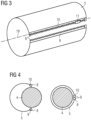
- FIG 3 shows an oblique view of a shell 5 of a third exemplary embodiment variant of a ballistic protection arrangement according to the invention with a zip fastener 8 .
- the zip fastener 8 is arranged on a lateral surface of the cylindrical shell 5 . It is straight and aligned parallel to a longitudinal axis 19 of the wheel set.
- the zipper 8 is welded to the shell 5, which is made of fiber-reinforced plastic. According to the invention it is also conceivable, for example, to weave the zipper 8 with the shell 5 .
- the shell 5 comprises a first layer of material 6 and a second layer of material 7, wherein the second layer of material 7 can be made of a metallic material and the zipper 8 can be welded to the second layer of material 7.
- the zipper 8 has a first row of staples 9 and a second row of staples 10 and a slider 11 .
- the slide 11 can be used to close and open the shell 5 staples of the first row of staples 9 and staples of the second row of staples 10 hooked into one another and released again.
- the zipper 8 is closed, the shell 5 is on an in 3 wheelset shaft 4 not shown fixed.
- a first state of a shell 5 of a third exemplary embodiment variant of a ballistic protection arrangement according to the invention with a zipper 8 is shown on the left and a second state on the right.
- the zipper 8 has a first row 9 of staples and a second row 10 of staples.
- the zip fastener 8 is open and the shell 5 is bent open and partially slipped over a wheelset axle 4 .
- the shell 5 encases the wheelset axle 4 and the zipper 8 is closed, i.e. the first row of staples 9 and the second row of staples 10 are hooked into one another.
- the shell 5 is fixed on the axle 4 in the second state.
- the shell 5 has a 1 illustrated and described first material layer 6 and a second material layer 7, wherein the first material layer 6 has a first fiber material with a fiber fabric.
- the second material layer 7 is designed as a thin steel sheet.
- the ballistic protection arrangement is therefore designed to be thin, light and flexible, resulting in less expense for assembly and disassembly, as in 4 shown on the left, the shell 5 is obtained.
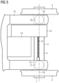
- figure 5 shows a running gear of a rail vehicle with a running gear frame 13, a drive motor/gear unit 14 connected to the running gear frame 13 and a first wheel set 1 with a first wheel 2, a second wheel 3 and a wheel set shaft 4.
- the first wheel set 1 is connected via a first wheel set bearing coupled to a first wheel set bearing housing 15 and via a second wheel set bearing to a second wheel set bearing housing 16 on the running gear frame 13 .
- a first primary spring 17 and a second primary spring 18 are arranged between the first wheel set 1 and the chassis frame.
- the drive motor gear unit 14 is coupled to the first wheel set 1 .
- FIG 5 A second set of wheels is not shown, which is designed in the same way as the first set of wheels 1 in terms of construction and with regard to its coupling to the running gear frame 13 .
- a ballistic protection arrangement is arranged on the wheel set shaft 4 in a region between the drive motor gear unit 14 and the first wheel set bearing housing 15 .
- This has a shell 5 which encases the wheelset shaft 4 .
- On the shell 5 is, as well as in 3 and 4 shown, a zipper 8 arranged. This is closed and the shell 5 is fixed on the wheelset shaft 4.
- a ballistic protection arrangement is located on a wheel set shaft 4 in an area between a drive motor gear unit 14 and a first wheel set bearing housing 15 arranged.
- This has a shell 5 which encases the wheelset shaft 4 .
- a button closure 12 is arranged on the shell 5 .
- the button closure 12 has a row of snaps on one side of the shell 5 and a row of recesses on the other side of the shell 5 .
- the snaps are in one in 6 assembly state shown snapped into the recesses.
- the button closure 12 is therefore closed and the shell 5 is fixed on the wheel set axle 4 .
- the shell 5 can be slid onto the wheelset shaft 4 in a manner similar to a stocking after a manufacturing process.
- the shell 5 rests against the wheel set shaft 4 and is fixed on the wheel set shaft 4 .
- first shell between the first axle box 15 and an in Figures 1 to 6 first wave brake disc, not shown
- second shell between the first wave brake disc and a second wave brake disc, also not shown, etc.
- the shell 5 comprises, for example, a first partial shell and a second partial shell, the cross sections of which have the same radii and which can be connected to one another via a first zipper and a second zipper.
Landscapes
- Engineering & Computer Science (AREA)
- Mechanical Engineering (AREA)
- General Engineering & Computer Science (AREA)
- Aiming, Guidance, Guns With A Light Source, Armor, Camouflage, And Targets (AREA)
- Laminated Bodies (AREA)
- Train Traffic Observation, Control, And Security (AREA)
- Exchange Systems With Centralized Control (AREA)
- Emergency Protection Circuit Devices (AREA)
Description
- Die Erfindung betrifft eine ballistische Schutzanordnung für Fahrzeuge, insbesondere für Fahrwerke von Schienenfahrzeugen mit zumindest einem ersten Radsatz, der ein erstes Rad, ein zweites Rad und eine Radsatzwelle aufweist.
- Komponenten von Fahrzeugen, beispielsweise Radsatzwellen von Fahrwerken für Schienenfahrzeuge, müssen vor Schäden geschützt sein. Radsatzwellen müssen dauerfest ausgelegt sein und hohen Belastungen, insbesondere auf Biegung und Torsion, standhalten.
- Die in den Europäischen Normen (EN), insbesondere in der EN 13104 und der EN 13103 sowie in den russischen Normen, insbesondere in der OCT 32.93-97 vorgeschriebenen Auslegungsmethoden gelten nur für nicht-korrodierte Werkstoffe und unbeschädigte Oberflächen. Aus diesem Grund müssen Radsatzwellen einen Korrosionsschutz aufweisen und dieser sowie die Radsatzwellen selbst müssen vor Oberflächenschäden, die beispielsweise von Steinschlag, Sand, Schnee und Eis sowie einer Einwirkung hoher oder tiefer Temperaturen verursacht werden können, geschützt sein.
- Treten Oberflächenschäden (z.B. Kerben) auf, müssen betroffene Radsatzwellen repariert werden, wodurch ein großer Instandhaltungsaufwand und hohe Instandhaltungskosten sowie eine geringe Verfügbarkeit der Fahrzeuge verursacht werden.
- Aus dem Stand der Technik ist beispielsweise die Radsatzwellenschutzanordnung Siemens Steel Rubber Axle Protection (SISRAP) bekannt. SISRAP schützt eine Radsatzwelle eines Schienenfahrzeugs z.B. vor Steinschlägen und umfasst eine tieftemperaturtaugliche Elastomermatte, Halbschalen aus nichtrostendem Stahlblech sowie Befestigungsbänder aus einem nichtrostenden Material.
- Die Elastomermatte weist eine Dicke von 3mm auf und ummantelt eine Radsatzwelle, auf der eine Korrosionsschutzbeschichtung vorgesehen ist. Die Elastomermatte ist wiederum von zwei halbzylindrischen Halbschalen mit Dicken von je 2mm ummantelt. Querschnitte der beiden Halbschalen weisen gleiche Radien auf.
- Die Radsatzwellenschutzanordnung SISRAP ist in der
DE 10 2010 009 437 A1 offenbart. - Der genannte Ansatz weist in seiner bekannten Form die Nachteile einer großen Masse der Radsatzwellenschutzanordnung sowie einer geringen Tauglichkeit für Fahrgeschwindigkeiten des Schienenfahrzeugs von größer als 250 km/h auf. Die Halbschalen müssten für Fahrgeschwindigkeiten von größer als 250 km/h in großer Dicke ausgeführt sein.
- Weiterhin müssen die Befestigungsbänder insbesondere bei Geschwindigkeiten über 250 km/h in großer Anzahl oder besonders dick oder ausgeführt werden, wodurch Masse und Trägheit der Radsatzwelle sowie erforderliche Antriebsleistungen des Schienenfahrzeugs steigen. Darüber hinaus ergeben sich dadurch ein erhöhter Platzbedarf im Bereich der Radsatzwelle sowie ein vergrößerter Aufwand für eine Montage und Demontage der Radsatzwellenschutzanordnung.
- Weiterhin zeigt die
WO 00/59764 - Das Rohr kann zwei Schichten aus unterschiedlichen Kunststoffen aufweisen. Weiterhin kann das Rohr mehrteilig ausgebildet sein. Es sind unterschiedliche Verschlussvorrichtungen dargestellt, wobei beispielsweise zwei Halbschalen über Schraubenverbindungen miteinander verbunden sind oder das Rohr einen Hakenverschluss aufweist.
- Ferner zeigt die
DE 20 2014 008 476 U1 eine röhrenförmige Schlagschutzvorrichtung, welche zwei Halbschalen und trichterförmige Endabschnitte aufweist. Es ist eine Trägerschicht aus Metall oder kohlefaserverstärktem Kunststoff vorgesehen, mit welcher Elastomer oder mit Elastomer durchsetztes Gewebe verbunden ist. - Die
EP 1 942 040 A1 offenbart einen Schutzmantel für eine Radsatzwelle eines Schienenfahrzeugs, bei der eine äußere Abschirmschicht und eine innere Dämpfungsschicht vorgesehen sind. Die äußere Schicht ist mit einem metallischen Film ummantelt und es kann mit ihr eine Verschlussvorrichtung verbunden sein. - Der Erfindung liegt die Aufgabe zugrunde, eine gegenüber dem Stand der Technik weiterentwickelte ballistische Schutzanordnung anzugeben.
- Erfindungsgemäß wird diese Aufgabe gelöst mit einer ballistischen Schutzanordnung mit den technischen Merkmalen des Anspruchs 1.
- Der Einsatz eines ersten Faserwerkstoffs, der beispielsweise Polyethylen-Fasern aufweisen kann, bewirkt eine hohe Energieabsorption bzw. Dämpfung bei Objekten (z.B. Basaltsteine mit einer Masse von bis zu 250 g), die bei einer Fahrgeschwindigkeit des Fahrzeugs von größer als 250 km/h auf die Radsatzwelle auftreffen. Der Radsatz ist gegen Deformationen und sonstige Schäden geschützt und es wird eine akustische Dämmung erzielt.
- Weiterhin kann die ballistische Schutzanordnung aufgrund des ersten Faserwerkstoffs mit geringer Dicke und leicht ausgeführt sein, wodurch eine geringe Masse und eine geringe Trägheit der Radsatzwelle erzielt werden.
- Es ist erfindungsgemäß vorgesehen, dass die Schale eine zweite Materialschicht aufweist.
- Die zweite Materialschicht kann beispielsweise in Stahl, Titan oder in einem faserverstärkten Kunststoff ausgeführt und mit der ersten Materialschicht verpresst sein. Der faserverstärkte Kunststoff kann beispielsweise einen zweiten Faserwerkstoff mit Glasfasern aufweisen sowie eine Matrix aus organischem Material.
- Aufgrund der zweiten Materialschicht wird eine hohe Zugfestigkeit der ballistischen Schutzanordnung und somit eine vorteilhafte Resistenz gegen auftreffende Objekte (z.B. Steine etc.) erzielt.
- Ein Verbund aus der ersten Materialschicht und der zweiten Materialschicht kann dünn und mit geringer Masse ausgeführt sein.
- Eine alternative, jedoch nicht beanspruchte, Ausgestaltung erhält man, wenn die erste Materialschicht als faserverstärkter Kunststoff mit dem ersten Faserwerkstoff und einem zweiten Faserwerkstoff ausgeführt ist.
- Durch diese Maßnahme wird eine ballistische Schutzanordnung mit nur einer Materialschicht, die jedoch zugleich eine hohe Energieabsorptionsfähigkeit, eine hohe Zugfestigkeit sowie eine geringe Dicke und Masse aufweist, erzielt. Der erste Faserwerkstoff kann beispielsweise Polyethylen-Fasern aufweisen, die mit dem zweiten Faserwerkstoff, beispielsweise mit Glasfasern und einer Matrix aus organischem Material, vermengt sind. Dadurch werden Eigenschaften einer hohen Energieabsorptionsfähigkeit und einer hohen Zugfestigkeit kombiniert.
- Eine günstige Lösung wird erzielt, wenn die Schale zumindest einen Reißverschluss aufweist.
- Dadurch wird eine leichte Montier- und Demontierbarkeit der ballistischen Schutzanordnung auf der Radsatzwelle bewirkt. Es sind keine Werkzeuge erforderlich.
- Weiterhin weist der Reißverschluss im Vergleich zu einem Hakenverschluss oder einer Schraubenverbindung einen geringen Platzbedarf sowie eine geringe Masse auf. Es sind außerdem keine zusätzlichen Verschlusssicherungen (z.B. Splinte) erforderlich.
- Nachfolgend wird die Erfindung anhand von Ausführungsbeispielen näher erläutert.
- Es zeigen beispielhaft:
- Fig. 1:
- Einen Seitenriss einer Radsatzwelle in geschnittener Darstellung mit einer ersten beispielhaften Ausführungsvariante einer erfindungsgemäßen ballistischen Schutzanordnung, die eine erste Materialschicht und eine zweite Materialschicht aufweist,
- Fig. 2:
- Einen Seitenriss einer Radsatzwelle in geschnittener Darstellung mit einer nicht den Ansprüchen entsprechenden ballistischen Schutzanordnung, die genau eine erste Materialschicht aufweist,
- Fig. 3:
- Einen Schrägriss einer Schale einer dritten beispielhaften Ausführungsvariante einer erfindungsgemäßen ballistischen Schutzanordnung, die einen Reißverschluss aufweist,
- Fig. 4:
- Zwei Seitenrisse einer Radsatzwelle in geschnittener Darstellung mit der dritten beispielhaften Ausführungsvariante einer erfindungsgemäßen ballistischen Schutzanordnung,
- Fig. 5:
- Eine Draufsicht auf einen Ausschnitt eines Fahrwerks mit einem ersten Radsatz, um dessen Radsatzwelle die dritte beispielhafte Ausführungsvariante einer erfindungsgemäßen ballistischen Schutzanordnung angeordnet ist, und
- Fig. 6:
- Eine Draufsicht auf einen Ausschnitt eines Fahrwerks mit einem ersten Radsatz, um dessen Radsatzwelle eine vierte beispielhafte Ausführungsvariante einer erfindungsgemäßen ballistischen Schutzanordnung mit einem Knopfverschluss angeordnet ist.
- Ein in
Fig. 1 dargestellter Seitenriss einer Radsatzwelle 4 eines Schienenfahrzeugs in geschnittener Darstellung mit einer ersten beispielhaften Ausführungsvariante einer erfindungsgemäßen ballistischen Schutzanordnung umfasst eine zylindrische Schale 5, die eine innenliegende erste Materialschicht 6 und eine außenliegende zweite Materialschicht 7 aufweist. - Die Radsatzwelle 4 weist eine nicht dargestellte Korrosionsschutzbeschichtung auf.
- Die Schale 5 ummantelt die Radsatzwelle 4 und ist mittels eines Reißverschlusses 8 gesichert.
- Es sind keine bzw. nur vernachlässigbare Bewegungen der Schale 5 relativ zu der Radsatzwelle 4 möglich, d.h. die Schale 5 ist auf der Radsatzwelle 4 fixiert.
- Die erste Materialschicht 6 ist mit der zweiten Materialschicht 7 verpresst, wobei für entsprechende Verpressungsvorgänge ein nicht dargestellter, aus dem Stand der Technik bekannter Autoklav eingesetzt wird.
- Die erste Materialschicht 6 weist einen ersten Faserwerkstoff mit einem Fasergewebe aus Kunstfasern, die in Polyethylen ausgebildet sind, auf, wodurch eine hohe Energieabsorptionsfähigkeit erzielt wird.
- Die zweite Materialschicht 7 ist in Stahl mit einer hohen Zugfestigkeit ausgeführt.
- Aufgrund der ersten Materialschicht 6 und der zweiten Materialschicht 7 sind Eigenschaften einer hohen Energieabsorptionsfähigkeit und einer hohen Zugfestigkeit in vorteilhafter Weise miteinander kombiniert.
- Erfindungsgemäß ist es auch denkbar, die zweite Materialschicht 7 in Titan oder faserverstärktem Kunststoff auszuführen. Bei einer Ausführung in faserverstärktem Kunststoff weist der faserverstärkte Kunststoff einen zweiten Faserwerkstoff aus Glasfasern sowie eine Matrix aus Epoxidharz mit Flammschutz auf. Erfindungsgemäß sind jedoch auch andere organische Matrixmaterialien, wie z.B. Polyurethan vorstellbar.
- Die Schale 5 weist eine Dicke von 6 mm auf und wird für Fahrgeschwindigkeiten des Schienenfahrzeugs von bis zu 380 km/h eingesetzt.
- In
Fig. 2 ist ein Seitenriss einer Radsatzwelle 4 eines Schienenfahrzeugs in geschnittener Darstellung mit einer zweiten, nicht beanspruchten Ausführung einer ballistischen Schutzanordnung dargestellt, wobei die ballistische Schutzanordnung eine zylindrische Schale 5 mit genau einer ersten Materialschicht 6 umfasst. - Die Radsatzwelle 4 weist eine nicht dargestellte Korrosionsschutzbeschichtung auf.
- Die Schale 5 ummantelt die Radsatzwelle 4 und ist mittels eines Reißverschlusses 8 fixiert.
- Die erste Materialschicht 6 ist in faserverstärktem Kunststoff ausgeführt. Der faserverstärkte Kunststoff weist einen ersten Faserwerkstoff aus Polyethylen-Fasern und einen zweiten Faserwerkstoff aus Glasfasern auf. Es ist ein Matrixmaterial aus Epoxidharz mit Flammschutz vorgesehen. Erfindungsgemäß sind jedoch auch andere organische Matrixmaterialien, wie z.B. Polyurethan vorstellbar.
- Der erste Faserwerkstoff ist mit dem zweiten Faserwerkstoff vermengt, wodurch Eigenschaften einer hohen Energieabsorptionsfähigkeit und einer hohen Zugfestigkeit in vorteilhafter Weise miteinander kombiniert sind.
-
Fig. 3 zeigt einen Schrägriss einer Schale 5 einer dritten beispielhaften Ausführungsvariante einer erfindungsgemäßen ballistischen Schutzanordnung mit einem Reißverschluss 8. Der Reißverschluss 8 ist auf einer Mantelfläche der zylindrischen Schale 5 angeordnet. Er ist geradlinig ausgeführt und parallel zu einer Radsatzlängsachse 19 ausgerichtet. - Der Reißverschluss 8 ist mit der Schale 5, die in einem faserverstärkten Kunststoff ausgeführt ist, verschweißt. Erfindungsgemäß ist es beispielsweise auch denkbar, den Reißverschluss 8 mit der Schale 5 zu verweben.
- Erfindungsgemäß umfasst die Schale 5 eine erste Materialschicht 6 und eine zweite Materialschicht 7, wobei die zweite Materialschicht 7 in einem metallischen Werkstoff ausgeführt werden kann und der Reißverschluss 8 mit der zweiten Materialschicht 7 verschweißt sein kann.
- Der Reißverschluss 8 weist eine erste Krampenreihe 9 und eine zweite Krampenreihe 10 sowie einen Schieber 11 auf. Mit dem Schieber 11 können zum Schließen und Öffnen der Schale 5 Krampen der ersten Krampenreihe 9 und Krampen der zweiten Krampenreihe 10 ineinander verhakt und wieder gelöst werden. In einem geschlossenen Zustand des Reißverschlusses 8 ist die Schale 5 auf einer in
Fig. 3 nicht gezeigten Radsatzwelle 4 fixiert. - In
Fig. 4 ist links ein erster Zustand einer Schale 5 einer dritten beispielhaften Ausführungsvariante einer erfindungsgemäßen ballistischen Schutzanordnung mit einem Reißverschluss 8 dargestellt und rechts ein zweiter Zustand. Der Reißverschluss 8 weist eine erste Krampenreihe 9 und eine zweite Krampenreihe 10 auf. - In dem ersten Zustand ist der Reißverschluss 8 geöffnet und die Schale 5 aufgebogen sowie teilweise über eine Radsatzwelle 4 gestülpt.
- In dem zweiten Zustand ummantelt die Schale 5 die Radsatzwelle 4 und der Reißverschluss 8 ist geschlossen, d.h. die erste Krampenreihe 9 und die zweite Krampenreihe 10 sind ineinander verhakt.
- Die Schale 5 ist in dem zweiten Zustand auf der Radsatzwelle 4 fixiert.
- Die Schale 5 weist eine in
Fig. 1 dargestellte und beschriebene erste Materialschicht 6 und eine zweite Materialschicht 7 auf, wobei die erste Materialschicht 6 einen ersten Faserwerkstoff mit einem Fasergewebe aufweist. Die zweite Materialschicht 7 ist als dünnes Stahlblech ausgeführt. Die ballistische Schutzanordnung ist daher dünn, leicht und biegsam ausgeführt, wodurch ein geringer Aufwand für Montage und Demontage, wie inFig. 4 links dargestellt, der Schale 5 erzielt wird. -
Fig. 5 zeigt ein Fahrwerk eines Schienenfahrzeugs mit einem Fahrwerksrahmen 13, einer mit dem Fahrwerksrahmen 13 verbundenen Antriebsmotor-Getriebeeinheit 14 sowie einem ersten Radsatz 1 mit einem ersten Rad 2, einem zweiten Rad 3 sowie einer Radsatzwelle 4. Der erste Radsatz 1 ist über ein erstes Radsatzlager mit einem ersten Radsatzlagergehäuse 15 sowie über ein zweites Radsatzlager mit einem zweiten Radsatzlagergehäuse 16 an den Fahrwerksrahmen 13 gekoppelt. Weiterhin sind zwischen dem ersten Radsatz 1 und dem Fahrwerksrahmen eine erste Primärfeder 17 und eine zweite Primärfeder 18 angeordnet. - Die Antriebsmotor-Getriebeeinheit 14 ist an den ersten Radsatz 1 gekoppelt.
- In
Fig. 5 nicht dargestellt ist ein zweiter Radsatz, der konstruktiv und im Hinblick auf seine Ankoppelung an den Fahrwerksrahmen 13 gleich wie der erste Radsatz 1 ausgeführt ist. - Auf der Radsatzwelle 4 ist in einem Bereich zwischen der Antriebsmotor-Getriebeeinheit 14 und dem ersten Radsatzlagergehäuse 15 eine ballistische Schutzanordnung angeordnet. Diese weist eine Schale 5 auf, welche die Radsatzwelle 4 ummantelt. Auf der Schale 5 ist, wie auch in
Fig. 3 und Fig. 4 dargestellt, ein Reißverschluss 8 angeordnet. Dieser ist geschlossen und die Schale 5 ist auf der Radsatzwelle 4 fixiert. - In
Fig. 6 ist ein Fahrwerk eines Schienenfahrzeugs dargestellt, das im Hinblick auf konstruktive Prinzipien jener Fahrwerksvariante entspricht, die inFig. 5 gezeigt wird. Es werden daher inFig. 6 teilweise die gleichen Bezugszeichen wie inFig. 5 verwendet. - Auf einer Radsatzwelle 4 ist in einem Bereich zwischen einer Antriebsmotor-Getriebeeinheit 14 und einem ersten Radsatzlagergehäuse 15 eine ballistische Schutzanordnung angeordnet. Diese weist eine Schale 5 auf, welche die Radsatzwelle 4 ummantelt. Auf der Schale 5 ist ein Knopfverschluss 12 angeordnet.
- Der Knopfverschluss 12 weist auf einer Seite der Schale 5 eine Knopfreihe mit Druckknöpfen auf, auf einer anderen Seite der Schale 5 eine Reihe mit Ausnehmungen.
- Die Druckknöpfe sind in einem in
Fig. 6 gezeigten Montagezustand in den Ausnehmungen eingerastet. Der Knopfverschluss 12 ist daher geschlossen und die Schale 5 ist auf der Radsatzwelle 4 fixiert. - Erfindungsgemäß ist es auch denkbar, auf einen Verschluss auf der Schale 5 zu verzichten und beispielsweise die Schale 5 aus einem besonders dehnbaren Material zu fertigen. Dadurch kann die Schale 5 ähnlich einem Strumpf nach einem Fertigungsvorgang der Radsatzwelle 4 auf diese geschoben werden. Die Schale 5 legt sich an die Radsatzwelle 4 an und ist auf der Radsatzwelle 4 fixiert.
- Weiterhin ist es auch möglich, mehrere Schalen 5 auf der Radsatzwelle 4 anzuordnen, beispielsweise eine erste Schale zwischen dem ersten Radsatzlagergehäuse 15 und einer in
Fig. 1 bis Fig. 6 nicht dargestellten ersten Wellenbremsscheibe und eine zweite Schale zwischen der ersten Wellenbremsscheibe und einer ebenfalls nicht gezeigten zweiten Wellenbremsscheibe etc. - Darüber hinaus ist es denkbar, dass die Schale 5 beispielsweise eine erste Teilschale und eine zweite Teilschale umfasst, deren Querschnitte gleiche Radien aufweisen und die über einen ersten Reißverschluss und einen zweiten Reißverschluss miteinander verbunden werden können.
-
- 1
- Erster Radsatz
- 2
- Erstes Rad
- 3
- Zweites Rad
- 4
- Radsatzwelle
- 5
- Schale
- 6
- Erste Materialschicht
- 7
- Zweite Materialschicht
- 8
- Reißverschluss
- 9
- Erste Krampenreihe
- 10
- Zweite Krampenreihe
- 11
- Schieber
- 12
- Knopfverschluss
- 13
- Fahrwerksrahmen
- 14
- Antriebsmotor-Getriebeeinheit
- 15
- Erstes Radsatzlagergehäuse
- 16
- Zweites Radsatzlagergehäuse
- 17
- Erste Primärfeder
- 18
- Zweite Primärfeder
- 19
- Radsatzlängsachse
Claims (11)
- Ballistische Schutzanordnung für Fahrzeuge, insbesondere für Fahrwerke von Schienenfahrzeugen mit zumindest einem ersten Radsatz, der ein erstes Rad, ein zweites Rad und eine Radsatzwelle aufweist, wobei eine Schale (5), welche zumindest eine erste Materialschicht (6), die einen ersten Faserwerkstoff aufweist, umfasst, um die Radsatzwelle (4) anordenbar ist, wobei die Schale (5) eine zweite Materialschicht (7) aufweist, dadurch gekennzeichnet, dass die erste Materialschicht (6) mit der zweiten Materialschicht (7) verpresst ist.
- Ballistische Schutzanordnung nach Anspruch 1, dadurch gekennzeichnet, dass der erste Faserwerkstoff der ersten Materialschicht (6) Polyethylen aufweist.
- Ballistische Schutzanordnung nach Anspruch 1 oder 2, dadurch gekennzeichnet, dass der erste Faserwerkstoff der ersten Materialschicht (6) als Fasergewebe ausgebildet ist.
- Ballistische Schutzanordnung nach einem der Ansprüche 1 bis 3, dadurch gekennzeichnet, dass die zweite Materialschicht (7) in einem metallischen Werkstoff ausgeführt ist.
- Ballistische Schutzanordnung nach einem der Ansprüche 1 bis 3, dadurch gekennzeichnet, dass die zweite Materialschicht (7) als faserverstärkter Kunststoff mit einem zweiten Faserwerkstoff, ausgeführt ist.
- Ballistische Schutzanordnung nach Anspruch 5,
dadurch gekennzeichnet, dass der zweite Faserwerkstoff Glasfasern aufweist. - Ballistische Schutzanordnung nach Anspruch 5 oder 6, dadurch gekennzeichnet, dass der faserverstärkte Kunststoff eine Matrix aus organischem Material aufweist.
- Ballistische Schutzanordnung nach einem der Ansprüche 1 bis 7, dadurch gekennzeichnet, dass die Schale (5) zumindest einen Reißverschluss (8) aufweist.
- Ballistische Schutzanordnung nach einem der Ansprüche 1 bis 8, dadurch gekennzeichnet, dass die Schale (5) zumindest einen Knopfverschluss (12) aufweist.
- Ballistische Schutzanordnung nach einem der Ansprüche 1 bis 9, dadurch gekennzeichnet, dass die Schale (5) zumindest eine erste Teilschale und eine zweite Teilschale umfasst, wobei ein erster Querschnitt der zumindest ersten Teilschale und ein zweiter Querschnitt der zweiten Teilschale gleiche Radien aufweisen.
- Ballistische Schutzanordnung nach einem der Ansprüche 1 bis 10, dadurch gekennzeichnet, dass die Schale (5) zylindrisch ausgeführt ist.
Applications Claiming Priority (2)
| Application Number | Priority Date | Filing Date | Title |
|---|---|---|---|
| ATA50203/2017A AT519717B1 (de) | 2017-03-14 | 2017-03-14 | Ballistische Schutzanordnung für Fahrzeuge |
| PCT/EP2018/056025 WO2018166949A1 (de) | 2017-03-14 | 2018-03-12 | Ballistische schutzanordnung für fahrzeuge |
Publications (2)
| Publication Number | Publication Date |
|---|---|
| EP3554917A1 EP3554917A1 (de) | 2019-10-23 |
| EP3554917B1 true EP3554917B1 (de) | 2023-04-26 |
Family
ID=61827686
Family Applications (1)
| Application Number | Title | Priority Date | Filing Date |
|---|---|---|---|
| EP18714152.8A Active EP3554917B1 (de) | 2017-03-14 | 2018-03-12 | Ballistische schutzanordnung für fahrzeuge |
Country Status (7)
| Country | Link |
|---|---|
| US (1) | US11597415B2 (de) |
| EP (1) | EP3554917B1 (de) |
| CN (1) | CN211809617U (de) |
| AT (1) | AT519717B1 (de) |
| ES (1) | ES2949530T3 (de) |
| PL (1) | PL3554917T3 (de) |
| WO (1) | WO2018166949A1 (de) |
Families Citing this family (5)
| Publication number | Priority date | Publication date | Assignee | Title |
|---|---|---|---|---|
| AT523425B1 (de) | 2020-03-12 | 2021-08-15 | Siemens Mobility Austria Gmbh | Rad für Fahrzeuge |
| IT202100029906A1 (it) * | 2021-11-26 | 2023-05-26 | A T P S P A | Sistema di protezione per assili ferroviari |
| CN117969629B (zh) * | 2024-04-02 | 2024-07-02 | 四川省疾病预防控制中心(四川省预防医学科学研究院四川省卫生监测检验中心) | 生理指标检测系统及方法 |
| AT527935B1 (de) | 2024-07-15 | 2025-08-15 | Siemens Mobility Austria Gmbh | Ballistische Schutzanordnung für Fahrzeuge, Radsatzwelle und Bearbeitungsverfahren |
| WO2026027056A1 (en) * | 2024-08-01 | 2026-02-05 | Geke Equitec Gmbh | Wheelset axle protection device and method of manufacturing such |
Family Cites Families (27)
| Publication number | Priority date | Publication date | Assignee | Title |
|---|---|---|---|---|
| US2747918A (en) * | 1953-02-12 | 1956-05-29 | Blackwood Waves | Railway vehicle axles |
| US2984486A (en) * | 1959-02-05 | 1961-05-16 | Lloyd J Jones | Slip-proof sleeve for a baseball bat handle |
| US4158407A (en) * | 1977-10-17 | 1979-06-19 | Rest Frederick G | Journal guard |
| US4352316A (en) * | 1978-06-30 | 1982-10-05 | Medlin Richard C | Lightweight armored vehicle and method of making same using woven polyester glass protective sheets |
| US4867444A (en) * | 1988-10-11 | 1989-09-19 | Castillo David D | Grip apparatus for weightlifting bar |
| US5700053A (en) * | 1994-10-27 | 1997-12-23 | Downing; David | Cushioning and protection apparatus for a chair armrest |
| FR2727508B1 (fr) * | 1994-11-30 | 1997-01-17 | Giat Ind Sa | Revetement pare-eclats pour vehicule blinde |
| DE19825402C1 (de) * | 1998-05-27 | 2000-02-10 | Abb Daimler Benz Transp | Selbsttragendes Formteil für mechanisch und korrosiv hochbeanspruchte, gekrümmt ausgebildete Bauteile eines Schienenfahrzeuges |
| ATE242438T1 (de) * | 1998-10-02 | 2003-06-15 | Oetiker Hans Maschinen | Vormontierte balgartige anordnung zum ummanteln von gelenkwellen |
| SE9901197L (sv) * | 1999-04-01 | 2000-09-18 | Daimler Chrysler Ag | Skydd för hjulaxel |
| US7232352B2 (en) * | 2002-09-10 | 2007-06-19 | Deborah Kutny Splaine | Paddle hand grips and method for making and using same |
| US8071206B1 (en) * | 2005-08-12 | 2011-12-06 | Touchstone Research Laboratory, Ltd. | Blast energy mitigating composite |
| US7222562B2 (en) * | 2005-08-30 | 2007-05-29 | Smiley Gary Leroy | Electromagnetic vehicle cover |
| FR2911102B1 (fr) * | 2007-01-05 | 2009-03-06 | Sncf | Manteau de protection d'essieu |
| US9513090B2 (en) * | 2009-08-03 | 2016-12-06 | Doo Kalmanson Aquino | Unobtrusive high-end ready to wear body armor garment |
| SE534733C2 (sv) * | 2010-01-13 | 2011-12-06 | Sj Ab | Skydd för en hjulaxel |
| DE102010009437A1 (de) * | 2010-02-22 | 2011-08-25 | Siemens Aktiengesellschaft, 80333 | Radsatzwellenschutz |
| DE102010022594A1 (de) * | 2010-05-31 | 2011-12-01 | Siemens Aktiengesellschaft | Radsatzwelle für ein schienengebundenes Fahrzeug mit Steinschlagschutz und Verfahren zu deren Herstellung |
| DE102012205220A1 (de) * | 2012-03-30 | 2013-10-02 | Siemens Aktiengesellschaft | Steinschlagschutzanordnung und Schienenfahrzeug mit einer Steinschlagschutzanordnung |
| US20140274614A1 (en) * | 2013-03-15 | 2014-09-18 | David R. Newman | Deformable grip pad with bistable spring bands and methods of use |
| DE102013212436B4 (de) * | 2013-06-27 | 2015-02-12 | Siemens Aktiengesellschaft | Schienenfahrzeug mit vor Schotterflug zu schützender Komponente |
| US10414921B1 (en) * | 2013-09-04 | 2019-09-17 | Virfex, LLC | Polyurethane foam based ballistic armor |
| DE202014002014U1 (de) * | 2014-03-07 | 2014-03-31 | Gmt Gummi-Metall-Technik Gmbh | Radsatzwellenschutz |
| US20160202023A1 (en) * | 2015-01-09 | 2016-07-14 | Chris Osman | Cutaway Vest |
| CA2977908C (en) * | 2015-01-09 | 2023-01-03 | Dsm Ip Assets B.V. | Lightweight laminates and plate-carrier vests and other articles of manufacture therefrom |
| IT201600081794A1 (it) * | 2016-08-03 | 2018-02-03 | Lucchini Rs Spa | Elemento di protezione di sale montate ferroviarie e relativo metodo di fabbricazione |
| US10806987B2 (en) * | 2016-12-22 | 2020-10-20 | Latisha Inez Burns | Barbell pad |
-
2017
- 2017-03-14 AT ATA50203/2017A patent/AT519717B1/de not_active IP Right Cessation
-
2018
- 2018-03-12 ES ES18714152T patent/ES2949530T3/es active Active
- 2018-03-12 CN CN201890000619.4U patent/CN211809617U/zh active Active
- 2018-03-12 US US16/493,927 patent/US11597415B2/en active Active
- 2018-03-12 EP EP18714152.8A patent/EP3554917B1/de active Active
- 2018-03-12 WO PCT/EP2018/056025 patent/WO2018166949A1/de not_active Ceased
- 2018-03-12 PL PL18714152.8T patent/PL3554917T3/pl unknown
Also Published As
| Publication number | Publication date |
|---|---|
| US11597415B2 (en) | 2023-03-07 |
| PL3554917T3 (pl) | 2023-08-28 |
| ES2949530T3 (es) | 2023-09-29 |
| AT519717A1 (de) | 2018-09-15 |
| CN211809617U (zh) | 2020-10-30 |
| US20210122400A1 (en) | 2021-04-29 |
| AT519717B1 (de) | 2019-06-15 |
| WO2018166949A1 (de) | 2018-09-20 |
| EP3554917A1 (de) | 2019-10-23 |
Similar Documents
| Publication | Publication Date | Title |
|---|---|---|
| EP3554917B1 (de) | Ballistische schutzanordnung für fahrzeuge | |
| EP3419840B1 (de) | Verwendung eines bauelements in fahrwerken von kraftfahrzeugen und verfahren zur herstellung von fahrwerken von kraftfahrzeugen | |
| EP3206937B1 (de) | Achsträger eines kraftfahrzeugs | |
| WO2012126923A1 (de) | Verbundwerkstoff und strukturbauteil für ein kraftfahrzeug | |
| EP1336470B1 (de) | Konstruktionselement aus faserverstärktem Kunststoff | |
| EP2423012A2 (de) | Faserverbundwerkstoffstabilisator | |
| EP2287447A2 (de) | Thermoplastendstufenschaufel | |
| DE102015202037A1 (de) | Bauteilanordnung | |
| DE102009058170A1 (de) | Blattfederanordnung | |
| DE102008024585B4 (de) | Federelement für eine Feder-Dämpfer-Anordnung | |
| DE102019109554A1 (de) | Biegefederelement aus einem Faserkunststoffverbundmaterial | |
| WO2012055489A1 (de) | Elastische lagerung für ein bauteil und verfahren zu deren herstellung | |
| EP2953843B1 (de) | Faserverstärkte versteifungsstrebe, herstellverfahren und kraftfahrzeugkarosserie | |
| EP2988984B1 (de) | Faserverstärkte versteifungsstrebe und kraftfahrzeugkarosserie | |
| DE10060042A1 (de) | Faserverstärktes Verbundbauteil aus Metall- und Kunststoffteilen und Verfahren zu dessen Herstellung | |
| DE4422579C2 (de) | Verbundbauteil als Zug-Druck-Stange für Schienenfahrzeuge | |
| DE102011079842B4 (de) | Vorrichtung mit einem Torsionsabschnitt | |
| DE102008055716A1 (de) | Fahrwerksteil eines Kraftfahrzeugs sowie Verfahren zum Herstellen desselben | |
| DE102015011707B4 (de) | Radaufhängungsbauteil für ein Kraftfahrzeug | |
| EP1308642B1 (de) | Hohlwelle | |
| AT504848B1 (de) | Wellenverbindung für einen antriebsstrang | |
| DE102013209102B4 (de) | Baugruppe für eine Kraftfahrzeugkarosserie | |
| DE102012221406A1 (de) | Gelenk, insbesondere für ein Kraftfahrzeug | |
| DE102011117298A1 (de) | Wellenkupplung | |
| DE102008058957A1 (de) | Querträger für ein Frontmodul eines Kraftfahrzeugs |
Legal Events
| Date | Code | Title | Description |
|---|---|---|---|
| STAA | Information on the status of an ep patent application or granted ep patent |
Free format text: STATUS: UNKNOWN |
|
| STAA | Information on the status of an ep patent application or granted ep patent |
Free format text: STATUS: THE INTERNATIONAL PUBLICATION HAS BEEN MADE |
|
| PUAI | Public reference made under article 153(3) epc to a published international application that has entered the european phase |
Free format text: ORIGINAL CODE: 0009012 |
|
| STAA | Information on the status of an ep patent application or granted ep patent |
Free format text: STATUS: REQUEST FOR EXAMINATION WAS MADE |
|
| 17P | Request for examination filed |
Effective date: 20190716 |
|
| AK | Designated contracting states |
Kind code of ref document: A1 Designated state(s): AL AT BE BG CH CY CZ DE DK EE ES FI FR GB GR HR HU IE IS IT LI LT LU LV MC MK MT NL NO PL PT RO RS SE SI SK SM TR |
|
| AX | Request for extension of the european patent |
Extension state: BA ME |
|
| RAP1 | Party data changed (applicant data changed or rights of an application transferred) |
Owner name: SIEMENS MOBILITY AUSTRIA GMBH |
|
| DAV | Request for validation of the european patent (deleted) | ||
| DAX | Request for extension of the european patent (deleted) | ||
| STAA | Information on the status of an ep patent application or granted ep patent |
Free format text: STATUS: EXAMINATION IS IN PROGRESS |
|
| 17Q | First examination report despatched |
Effective date: 20210426 |
|
| RIC1 | Information provided on ipc code assigned before grant |
Ipc: B61F 5/50 20060101ALI20220914BHEP Ipc: B61F 19/00 20060101AFI20220914BHEP |
|
| GRAP | Despatch of communication of intention to grant a patent |
Free format text: ORIGINAL CODE: EPIDOSNIGR1 |
|
| STAA | Information on the status of an ep patent application or granted ep patent |
Free format text: STATUS: GRANT OF PATENT IS INTENDED |
|
| INTG | Intention to grant announced |
Effective date: 20221128 |
|
| GRAS | Grant fee paid |
Free format text: ORIGINAL CODE: EPIDOSNIGR3 |
|
| GRAA | (expected) grant |
Free format text: ORIGINAL CODE: 0009210 |
|
| STAA | Information on the status of an ep patent application or granted ep patent |
Free format text: STATUS: THE PATENT HAS BEEN GRANTED |
|
| AK | Designated contracting states |
Kind code of ref document: B1 Designated state(s): AL AT BE BG CH CY CZ DE DK EE ES FI FR GB GR HR HU IE IS IT LI LT LU LV MC MK MT NL NO PL PT RO RS SE SI SK SM TR |
|
| REG | Reference to a national code |
Ref country code: GB Ref legal event code: FG4D Free format text: NOT ENGLISH |
|
| REG | Reference to a national code |
Ref country code: CH Ref legal event code: EP |
|
| REG | Reference to a national code |
Ref country code: DE Ref legal event code: R096 Ref document number: 502018012030 Country of ref document: DE |
|
| REG | Reference to a national code |
Ref country code: AT Ref legal event code: REF Ref document number: 1562631 Country of ref document: AT Kind code of ref document: T Effective date: 20230515 |
|
| REG | Reference to a national code |
Ref country code: IE Ref legal event code: FG4D Free format text: LANGUAGE OF EP DOCUMENT: GERMAN |
|
| REG | Reference to a national code |
Ref country code: LT Ref legal event code: MG9D |
|
| REG | Reference to a national code |
Ref country code: NL Ref legal event code: MP Effective date: 20230426 |
|
| PG25 | Lapsed in a contracting state [announced via postgrant information from national office to epo] |
Ref country code: NL Free format text: LAPSE BECAUSE OF FAILURE TO SUBMIT A TRANSLATION OF THE DESCRIPTION OR TO PAY THE FEE WITHIN THE PRESCRIBED TIME-LIMIT Effective date: 20230426 |
|
| REG | Reference to a national code |
Ref country code: ES Ref legal event code: FG2A Ref document number: 2949530 Country of ref document: ES Kind code of ref document: T3 Effective date: 20230929 |
|
| PG25 | Lapsed in a contracting state [announced via postgrant information from national office to epo] |
Ref country code: SE Free format text: LAPSE BECAUSE OF FAILURE TO SUBMIT A TRANSLATION OF THE DESCRIPTION OR TO PAY THE FEE WITHIN THE PRESCRIBED TIME-LIMIT Effective date: 20230426 Ref country code: PT Free format text: LAPSE BECAUSE OF FAILURE TO SUBMIT A TRANSLATION OF THE DESCRIPTION OR TO PAY THE FEE WITHIN THE PRESCRIBED TIME-LIMIT Effective date: 20230828 Ref country code: NO Free format text: LAPSE BECAUSE OF FAILURE TO SUBMIT A TRANSLATION OF THE DESCRIPTION OR TO PAY THE FEE WITHIN THE PRESCRIBED TIME-LIMIT Effective date: 20230726 |
|
| PG25 | Lapsed in a contracting state [announced via postgrant information from national office to epo] |
Ref country code: RS Free format text: LAPSE BECAUSE OF FAILURE TO SUBMIT A TRANSLATION OF THE DESCRIPTION OR TO PAY THE FEE WITHIN THE PRESCRIBED TIME-LIMIT Effective date: 20230426 Ref country code: LV Free format text: LAPSE BECAUSE OF FAILURE TO SUBMIT A TRANSLATION OF THE DESCRIPTION OR TO PAY THE FEE WITHIN THE PRESCRIBED TIME-LIMIT Effective date: 20230426 Ref country code: LT Free format text: LAPSE BECAUSE OF FAILURE TO SUBMIT A TRANSLATION OF THE DESCRIPTION OR TO PAY THE FEE WITHIN THE PRESCRIBED TIME-LIMIT Effective date: 20230426 Ref country code: IS Free format text: LAPSE BECAUSE OF FAILURE TO SUBMIT A TRANSLATION OF THE DESCRIPTION OR TO PAY THE FEE WITHIN THE PRESCRIBED TIME-LIMIT Effective date: 20230826 Ref country code: HR Free format text: LAPSE BECAUSE OF FAILURE TO SUBMIT A TRANSLATION OF THE DESCRIPTION OR TO PAY THE FEE WITHIN THE PRESCRIBED TIME-LIMIT Effective date: 20230426 Ref country code: GR Free format text: LAPSE BECAUSE OF FAILURE TO SUBMIT A TRANSLATION OF THE DESCRIPTION OR TO PAY THE FEE WITHIN THE PRESCRIBED TIME-LIMIT Effective date: 20230727 |
|
| PG25 | Lapsed in a contracting state [announced via postgrant information from national office to epo] |
Ref country code: FI Free format text: LAPSE BECAUSE OF FAILURE TO SUBMIT A TRANSLATION OF THE DESCRIPTION OR TO PAY THE FEE WITHIN THE PRESCRIBED TIME-LIMIT Effective date: 20230426 |
|
| PG25 | Lapsed in a contracting state [announced via postgrant information from national office to epo] |
Ref country code: SK Free format text: LAPSE BECAUSE OF FAILURE TO SUBMIT A TRANSLATION OF THE DESCRIPTION OR TO PAY THE FEE WITHIN THE PRESCRIBED TIME-LIMIT Effective date: 20230426 |
|
| REG | Reference to a national code |
Ref country code: DE Ref legal event code: R097 Ref document number: 502018012030 Country of ref document: DE |
|
| PG25 | Lapsed in a contracting state [announced via postgrant information from national office to epo] |
Ref country code: SM Free format text: LAPSE BECAUSE OF FAILURE TO SUBMIT A TRANSLATION OF THE DESCRIPTION OR TO PAY THE FEE WITHIN THE PRESCRIBED TIME-LIMIT Effective date: 20230426 Ref country code: SK Free format text: LAPSE BECAUSE OF FAILURE TO SUBMIT A TRANSLATION OF THE DESCRIPTION OR TO PAY THE FEE WITHIN THE PRESCRIBED TIME-LIMIT Effective date: 20230426 Ref country code: RO Free format text: LAPSE BECAUSE OF FAILURE TO SUBMIT A TRANSLATION OF THE DESCRIPTION OR TO PAY THE FEE WITHIN THE PRESCRIBED TIME-LIMIT Effective date: 20230426 Ref country code: EE Free format text: LAPSE BECAUSE OF FAILURE TO SUBMIT A TRANSLATION OF THE DESCRIPTION OR TO PAY THE FEE WITHIN THE PRESCRIBED TIME-LIMIT Effective date: 20230426 Ref country code: DK Free format text: LAPSE BECAUSE OF FAILURE TO SUBMIT A TRANSLATION OF THE DESCRIPTION OR TO PAY THE FEE WITHIN THE PRESCRIBED TIME-LIMIT Effective date: 20230426 |
|
| PLBE | No opposition filed within time limit |
Free format text: ORIGINAL CODE: 0009261 |
|
| STAA | Information on the status of an ep patent application or granted ep patent |
Free format text: STATUS: NO OPPOSITION FILED WITHIN TIME LIMIT |
|
| 26N | No opposition filed |
Effective date: 20240129 |
|
| PG25 | Lapsed in a contracting state [announced via postgrant information from national office to epo] |
Ref country code: SI Free format text: LAPSE BECAUSE OF FAILURE TO SUBMIT A TRANSLATION OF THE DESCRIPTION OR TO PAY THE FEE WITHIN THE PRESCRIBED TIME-LIMIT Effective date: 20230426 |
|
| PG25 | Lapsed in a contracting state [announced via postgrant information from national office to epo] |
Ref country code: SI Free format text: LAPSE BECAUSE OF FAILURE TO SUBMIT A TRANSLATION OF THE DESCRIPTION OR TO PAY THE FEE WITHIN THE PRESCRIBED TIME-LIMIT Effective date: 20230426 |
|
| PG25 | Lapsed in a contracting state [announced via postgrant information from national office to epo] |
Ref country code: BG Free format text: LAPSE BECAUSE OF FAILURE TO SUBMIT A TRANSLATION OF THE DESCRIPTION OR TO PAY THE FEE WITHIN THE PRESCRIBED TIME-LIMIT Effective date: 20230426 |
|
| PG25 | Lapsed in a contracting state [announced via postgrant information from national office to epo] |
Ref country code: LU Free format text: LAPSE BECAUSE OF NON-PAYMENT OF DUE FEES Effective date: 20240312 |
|
| PG25 | Lapsed in a contracting state [announced via postgrant information from national office to epo] |
Ref country code: MC Free format text: LAPSE BECAUSE OF FAILURE TO SUBMIT A TRANSLATION OF THE DESCRIPTION OR TO PAY THE FEE WITHIN THE PRESCRIBED TIME-LIMIT Effective date: 20230426 |
|
| PG25 | Lapsed in a contracting state [announced via postgrant information from national office to epo] |
Ref country code: MC Free format text: LAPSE BECAUSE OF FAILURE TO SUBMIT A TRANSLATION OF THE DESCRIPTION OR TO PAY THE FEE WITHIN THE PRESCRIBED TIME-LIMIT Effective date: 20230426 Ref country code: LU Free format text: LAPSE BECAUSE OF NON-PAYMENT OF DUE FEES Effective date: 20240312 Ref country code: BG Free format text: LAPSE BECAUSE OF FAILURE TO SUBMIT A TRANSLATION OF THE DESCRIPTION OR TO PAY THE FEE WITHIN THE PRESCRIBED TIME-LIMIT Effective date: 20230426 |
|
| REG | Reference to a national code |
Ref country code: BE Ref legal event code: MM Effective date: 20240331 |
|
| PG25 | Lapsed in a contracting state [announced via postgrant information from national office to epo] |
Ref country code: BE Free format text: LAPSE BECAUSE OF NON-PAYMENT OF DUE FEES Effective date: 20240331 |
|
| PG25 | Lapsed in a contracting state [announced via postgrant information from national office to epo] |
Ref country code: IE Free format text: LAPSE BECAUSE OF NON-PAYMENT OF DUE FEES Effective date: 20240312 |
|
| PG25 | Lapsed in a contracting state [announced via postgrant information from national office to epo] |
Ref country code: IE Free format text: LAPSE BECAUSE OF NON-PAYMENT OF DUE FEES Effective date: 20240312 Ref country code: BE Free format text: LAPSE BECAUSE OF NON-PAYMENT OF DUE FEES Effective date: 20240331 |
|
| PGFP | Annual fee paid to national office [announced via postgrant information from national office to epo] |
Ref country code: DE Payment date: 20250520 Year of fee payment: 8 |
|
| PGFP | Annual fee paid to national office [announced via postgrant information from national office to epo] |
Ref country code: GB Payment date: 20250403 Year of fee payment: 8 Ref country code: ES Payment date: 20250620 Year of fee payment: 8 |
|
| PGFP | Annual fee paid to national office [announced via postgrant information from national office to epo] |
Ref country code: CH Payment date: 20250611 Year of fee payment: 8 |
|
| PG25 | Lapsed in a contracting state [announced via postgrant information from national office to epo] |
Ref country code: CY Free format text: LAPSE BECAUSE OF FAILURE TO SUBMIT A TRANSLATION OF THE DESCRIPTION OR TO PAY THE FEE WITHIN THE PRESCRIBED TIME-LIMIT; INVALID AB INITIO Effective date: 20180312 |
|
| PG25 | Lapsed in a contracting state [announced via postgrant information from national office to epo] |
Ref country code: HU Free format text: LAPSE BECAUSE OF FAILURE TO SUBMIT A TRANSLATION OF THE DESCRIPTION OR TO PAY THE FEE WITHIN THE PRESCRIBED TIME-LIMIT; INVALID AB INITIO Effective date: 20180312 |
|
| PG25 | Lapsed in a contracting state [announced via postgrant information from national office to epo] |
Ref country code: TR Free format text: LAPSE BECAUSE OF FAILURE TO SUBMIT A TRANSLATION OF THE DESCRIPTION OR TO PAY THE FEE WITHIN THE PRESCRIBED TIME-LIMIT Effective date: 20230426 |
|
| PGFP | Annual fee paid to national office [announced via postgrant information from national office to epo] |
Ref country code: AT Payment date: 20260206 Year of fee payment: 9 |
|
| PGFP | Annual fee paid to national office [announced via postgrant information from national office to epo] |
Ref country code: IT Payment date: 20260324 Year of fee payment: 9 |
|
| PGFP | Annual fee paid to national office [announced via postgrant information from national office to epo] |
Ref country code: FR Payment date: 20260316 Year of fee payment: 9 |
|
| PGFP | Annual fee paid to national office [announced via postgrant information from national office to epo] |
Ref country code: CZ Payment date: 20260306 Year of fee payment: 9 |
|
| PGFP | Annual fee paid to national office [announced via postgrant information from national office to epo] |
Ref country code: PL Payment date: 20260226 Year of fee payment: 9 |