EP3877296B1 - Système de stockage et de récupération automatisé - Google Patents
Système de stockage et de récupération automatisé Download PDFInfo
- Publication number
- EP3877296B1 EP3877296B1 EP19789907.3A EP19789907A EP3877296B1 EP 3877296 B1 EP3877296 B1 EP 3877296B1 EP 19789907 A EP19789907 A EP 19789907A EP 3877296 B1 EP3877296 B1 EP 3877296B1
- Authority
- EP
- European Patent Office
- Prior art keywords
- container
- vehicle
- grid
- storage
- picking
- Prior art date
- Legal status (The legal status is an assumption and is not a legal conclusion. Google has not performed a legal analysis and makes no representation as to the accuracy of the status listed.)
- Active
Links
- 238000003860 storage Methods 0.000 title claims description 197
- 230000007246 mechanism Effects 0.000 claims description 38
- 238000004891 communication Methods 0.000 claims description 8
- 238000000034 method Methods 0.000 claims description 8
- 241000237519 Bivalvia Species 0.000 claims 1
- 235000020639 clam Nutrition 0.000 claims 1
- 238000012546 transfer Methods 0.000 description 4
- 238000004140 cleaning Methods 0.000 description 2
- 238000012544 monitoring process Methods 0.000 description 2
- 229910052782 aluminium Inorganic materials 0.000 description 1
- XAGFODPZIPBFFR-UHFFFAOYSA-N aluminium Chemical compound [Al] XAGFODPZIPBFFR-UHFFFAOYSA-N 0.000 description 1
- 210000000078 claw Anatomy 0.000 description 1
- 238000010276 construction Methods 0.000 description 1
- 238000012423 maintenance Methods 0.000 description 1
- 238000004519 manufacturing process Methods 0.000 description 1
- 229910052751 metal Inorganic materials 0.000 description 1
- 239000002184 metal Substances 0.000 description 1
- 238000012986 modification Methods 0.000 description 1
- 230000004048 modification Effects 0.000 description 1
- 238000003032 molecular docking Methods 0.000 description 1
- 239000005022 packaging material Substances 0.000 description 1
- 230000003245 working effect Effects 0.000 description 1
Images


Classifications
-
- B—PERFORMING OPERATIONS; TRANSPORTING
- B65—CONVEYING; PACKING; STORING; HANDLING THIN OR FILAMENTARY MATERIAL
- B65G—TRANSPORT OR STORAGE DEVICES, e.g. CONVEYORS FOR LOADING OR TIPPING, SHOP CONVEYOR SYSTEMS OR PNEUMATIC TUBE CONVEYORS
- B65G1/00—Storing articles, individually or in orderly arrangement, in warehouses or magazines
- B65G1/02—Storage devices
- B65G1/04—Storage devices mechanical
- B65G1/0478—Storage devices mechanical for matrix-arrangements
-
- B—PERFORMING OPERATIONS; TRANSPORTING
- B65—CONVEYING; PACKING; STORING; HANDLING THIN OR FILAMENTARY MATERIAL
- B65G—TRANSPORT OR STORAGE DEVICES, e.g. CONVEYORS FOR LOADING OR TIPPING, SHOP CONVEYOR SYSTEMS OR PNEUMATIC TUBE CONVEYORS
- B65G1/00—Storing articles, individually or in orderly arrangement, in warehouses or magazines
- B65G1/02—Storage devices
- B65G1/04—Storage devices mechanical
- B65G1/0464—Storage devices mechanical with access from above
-
- B—PERFORMING OPERATIONS; TRANSPORTING
- B65—CONVEYING; PACKING; STORING; HANDLING THIN OR FILAMENTARY MATERIAL
- B65G—TRANSPORT OR STORAGE DEVICES, e.g. CONVEYORS FOR LOADING OR TIPPING, SHOP CONVEYOR SYSTEMS OR PNEUMATIC TUBE CONVEYORS
- B65G1/00—Storing articles, individually or in orderly arrangement, in warehouses or magazines
- B65G1/02—Storage devices
- B65G1/04—Storage devices mechanical
- B65G1/0407—Storage devices mechanical using stacker cranes
- B65G1/0421—Storage devices mechanical using stacker cranes with control for stacker crane operations
-
- B—PERFORMING OPERATIONS; TRANSPORTING
- B65—CONVEYING; PACKING; STORING; HANDLING THIN OR FILAMENTARY MATERIAL
- B65G—TRANSPORT OR STORAGE DEVICES, e.g. CONVEYORS FOR LOADING OR TIPPING, SHOP CONVEYOR SYSTEMS OR PNEUMATIC TUBE CONVEYORS
- B65G1/00—Storing articles, individually or in orderly arrangement, in warehouses or magazines
- B65G1/02—Storage devices
- B65G1/04—Storage devices mechanical
- B65G1/0457—Storage devices mechanical with suspended load carriers
-
- B—PERFORMING OPERATIONS; TRANSPORTING
- B65—CONVEYING; PACKING; STORING; HANDLING THIN OR FILAMENTARY MATERIAL
- B65G—TRANSPORT OR STORAGE DEVICES, e.g. CONVEYORS FOR LOADING OR TIPPING, SHOP CONVEYOR SYSTEMS OR PNEUMATIC TUBE CONVEYORS
- B65G1/00—Storing articles, individually or in orderly arrangement, in warehouses or magazines
- B65G1/02—Storage devices
- B65G1/04—Storage devices mechanical
- B65G1/0485—Check-in, check-out devices
-
- B—PERFORMING OPERATIONS; TRANSPORTING
- B65—CONVEYING; PACKING; STORING; HANDLING THIN OR FILAMENTARY MATERIAL
- B65G—TRANSPORT OR STORAGE DEVICES, e.g. CONVEYORS FOR LOADING OR TIPPING, SHOP CONVEYOR SYSTEMS OR PNEUMATIC TUBE CONVEYORS
- B65G1/00—Storing articles, individually or in orderly arrangement, in warehouses or magazines
- B65G1/02—Storage devices
- B65G1/04—Storage devices mechanical
- B65G1/137—Storage devices mechanical with arrangements or automatic control means for selecting which articles are to be removed
- B65G1/1373—Storage devices mechanical with arrangements or automatic control means for selecting which articles are to be removed for fulfilling orders in warehouses
-
- B—PERFORMING OPERATIONS; TRANSPORTING
- B66—HOISTING; LIFTING; HAULING
- B66F—HOISTING, LIFTING, HAULING OR PUSHING, NOT OTHERWISE PROVIDED FOR, e.g. DEVICES WHICH APPLY A LIFTING OR PUSHING FORCE DIRECTLY TO THE SURFACE OF A LOAD
- B66F9/00—Devices for lifting or lowering bulky or heavy goods for loading or unloading purposes
- B66F9/06—Devices for lifting or lowering bulky or heavy goods for loading or unloading purposes movable, with their loads, on wheels or the like, e.g. fork-lift trucks
- B66F9/063—Automatically guided
Definitions
- the present invention relates to a remotely operated vehicle assembly for an automated storage and retrieval system for moving a product item between a storage container stored in an automated storage and retrieval grid configured to store a plurality of stacks of storage containers.
- the present invention also relates to a method for moving a product item between a storage container stored in an automated storage and retrieval grid of an automated storage and retrieval system.
- the present invention also relates to an automated storage and retrieval system.
- Figs. 1A and 1C disclose a typical prior art automated storage and retrieval system 1 with a framework structure 100.
- Figs. 1B and 1D disclose a prior art container handling vehicle 101 operating the system 1 disclosed in Figs. 1A and 1C , respectively.
- the framework structure 100 comprises a plurality of upright members 102 and optionally a plurality of horizontal members 103 supporting the upright members 102.
- the members 102, 103 may typically be made of metal, e.g. extruded aluminum profiles.
- the framework structure 100 defines a storage grid 104 comprising storage columns 105 arranged in rows, in which storage columns 105 storage containers 106, also known as bins, are stacked one on top of another to form stacks 107.
- Each storage container 106 may typically hold a plurality of product items (not shown), and the product items within a storage container 106 may be identical, or may be of different product types depending on the application.
- the storage grid 104 guards against horizontal movement of the storage containers 106 in the stacks 107, and guides vertical movement of the storage containers 106, but does normally not otherwise support the storage containers 106 when stacked.
- the automated storage and retrieval system 1 comprises a container handling vehicle rail system 108 arranged in a grid pattern across the top of the storage 104, on which rail system 108 a plurality of container handling vehicles 200,300 (as exemplified in Figs. 1B and ID) are operated to raise storage containers 106 from, and lower storage containers 106 into, the storage columns 105, and also to transport the storage containers 106 above the storage columns 105.
- the horizontal extent of one of the grid cells 122 constituting the grid pattern is in Figs. 1A and 1C marked by thick lines.
- Each grid cell 122 has a width which is typically within the interval of 30 to 150 cm, and a length which is typically within the interval of 50 to 200 cm.
- Each grid opening 115 has a width and a length which is typically 2 to 10 cm less than the width and the length of the grid cell 122 due to the horizontal extent of the rails 110,111.
- the rail system 108 comprises a first set of parallel rails 110 arranged to guide movement of the container handling vehicles 200,300 in a first direction X across the top of the frame structure 100, and a second set of parallel rails 111 arranged perpendicular to the first set of rails 110 to guide movement of the container handling vehicles 200,300 in a second direction Y which is perpendicular to the first direction X.
- the rail system 108 defines grid columns above which the container handling vehicles 200,300 can move laterally above the storage columns 105, i.e. in a plane which is parallel to the horizontal X-Y plane.
- Each prior art container handling vehicle 200,300 comprises a vehicle body and a wheel arrangement of eight wheels 201,301 where a first set of four wheels enable the lateral movement of the container handling vehicles 200,300 in the X direction and a second set of the remaining four wheels enable the lateral movement in the Y direction.
- One or both sets of wheels in the wheel arrangement can be lifted and lowered, so that the first set of wheels and/or the second set of wheels can be engaged with the respective set of rails 110, 111 at any one time.
- Each prior art container handling vehicle 200,300 also comprises a lifting device (not shown) for vertical transportation of storage containers 106, e.g. raising a storage container 106 from, and lowering a storage container 106 into, a storage column 105.
- the lifting device comprises one or more gripping / engaging devices (not shown) which are adapted to engage a storage container 106, and which gripping / engaging devices can be lowered from the vehicle 20,300 so that the position of the gripping / engaging devices with respect to the vehicle 200,300 can be adjusted in a third direction Z which is orthogonal the first direction X and the second direction Y.
- Each container handling vehicle 200 comprises a storage compartment or space (not shown) for receiving and stowing a storage container 106 when transporting the storage container 106 across the rail system 108.
- the storage space may comprise a cavity arranged centrally within the vehicle body, e.g. as is described in WO2014/090684A1 .
- the container handling vehicles 300 may have a cantilever construction, as is described in NO3173 66.
- the container handling vehicles 200 may have a footprint, i.e. an extent in the X and Y directions, which is generally equal to the lateral extent of a grid cell 122, i.e. the extent of a grid cell 122 in the X and Y directions, e.g. as is described in WO2015/193278A1 .
- lateral used herein may mean “horizontal”.
- the container handling vehicles 200 may have a footprint which is larger than the lateral extent of (lateral area defined by) a grid column 105, e.g. as is disclosed in WO2014/090684A1 .
- the rail system 108 may be a single track system, as is shown in Fig. 2A .
- the rail system 108 may be a double track system, as is shown in Fig. 2B , thus allowing a container handling vehicle 201 having a footprint 202,202' generally corresponding to the lateral area defined by a grid column 112 to travel along a row of grid columns even if another container handling vehicle 200 is positioned above a grid column neighboring that row.
- Both the single and double track system, or a combination comprising a single and double track arrangement in a single rail system 108 forms a grid pattern in the horizontal plane P comprising a plurality of rectangular and uniform grid locations or grid cells 122, where each grid cell 122 comprises a grid opening 115 being delimited by a pair of rails 110a,110b of the first rails 110 and a pair of rails 111a,111b of the second set of rails 111.
- the grid cell 122 is indicated by a dashed box.
- rails 110a and 110b form pairs of neighboring rails defining parallel rows of grid cells running in the X direction
- rails 111a and 111b form pairs of neighboring rails defining parallel rows of grid cells running in the Y direction.
- each grid cell 122 has a width W c which is typically within the interval of 30 to 150 cm, and a length L c which is typically within the interval of 50 to 200 cm.
- Each grid opening 115 has a width W o and a length L o which is typically 2 to 10 cm less than the width W c and the length L c of the grid cell 122.
- neighboring grid cells 122 are arranged in contact with each other such that there is no space there-between.
- a majority of the grid columns are storage columns 105, i.e. grid columns 105 where storage containers 106 are stored in stacks 107.
- a grid 104 normally has at least one grid column which is used not for storing storage containers 106, but which comprises a location where the container handling vehicles 200,300 can drop off and/or pick up storage containers 106 so that they can be transported to a second location (not shown) where the storage containers 106 can be accessed from outside of the grid 104 or transferred out of or into the grid 104.
- a location is normally referred to as a "port” and the grid column in which the port is located may be referred to as a "delivery column" 119,120.
- the drop-off and pick-up ports of the container handling vehicles are referred to as the "upper ports of a delivery column" 119,120. While the opposite end of the delivery column is referred to as the "lower ports of a delivery column”.
- the storage grids 104 in Figs. 1A and 1C comprise two delivery columns 119 and 120.
- the first delivery column 119 may for example comprise a dedicated drop-off port where the container handling vehicles 200,300 can drop off storage containers 106 to be transported through the delivery column 119 and further to an access or a transfer station (not shown), and the second delivery column 120 may comprise a dedicated pick-up port where the container handling vehicles 200,300 can pick up storage containers 106 that have been transported through the delivery column 120 from an access or a transfer station (not shown).
- Each of the ports of the first and second delivery column 119,120 may comprise a port suitable for both pick up and drop of storage containers 106.
- the second location may typically be a picking or a stocking station where product items are removed from or positioned into the storage containers 106.
- the storage containers 106 are normally never removed from the automated storage and retrieval system 1, but are returned into the storage grid 104 once accessed.
- there are also lower ports provided in a delivery column such lower ports are e.g. for transferring storage containers 106 to another storage facility (e.g. to another storage grid), directly to a transport vehicle (e.g. a train or a lorry), or to a production facility.
- the automated storage and retrieval system 1 For monitoring and controlling the automated storage and retrieval system 1 (e.g. monitoring and controlling the location of respective storage containers 106 within the storage grid 104; the content of each storage container 106; and the movement of the container handling vehicles 200,300 so that a desired storage container 106 can be delivered to the desired location at the desired time without the container handling vehicles 200,300 colliding with each other), the automated storage and retrieval system 1 comprises a control system (not shown) which typically is computerized and which typically comprises a database for keeping track of the storage containers 106.
- a conveyor system comprising conveyors may be employed to transport the storage containers between the lower port of the delivery column 119,120 and the access station.
- the conveyor system may comprise a lift device for transporting the storage containers 106 vertically between the port and the access station.
- the conveyor system may be arranged to transfer storage containers between different grids, e.g. as is described in WO2014/075937A1 .
- WO2016/198467A1 discloses an example of a prior art access system having conveyor belts (Figs. 5a and 5b in WO2016/198467A1 ) and a frame mounted rail (Figs. 6a and 6b in WO2016/198467A1 ) for transporting storage containers between delivery columns and work stations where operators can access the storage containers.
- a storage container 106 stored in the grid 104 disclosed in Fig. 1A When a storage container 106 stored in the grid 104 disclosed in Fig. 1A is to be accessed, one of the container handling vehicles 200,300 is instructed to retrieve the target storage container 106 from its position in the grid 104 and to transport it to or through the delivery column 119.
- This operation involves moving the container handling vehicle 200,300 to a grid location above the storage column 105 in which the target storage container 106 is positioned, retrieving the storage container 106 from the storage column 105 using the container handling vehicle's lifting device (not shown), and transporting the storage container 106 to the delivery column 119. If the target storage container 106 is located deep within a stack 107, i.e.
- the operation also involves temporarily moving the above-positioned storage containers prior to lifting the target storage container 106 from the storage column 105.
- This step which is sometimes referred to as "digging" within the art, may be performed with the same container handling vehicle 200,300 that is subsequently used for transporting the target storage container 106 to the delivery column, or with one or a plurality of other cooperating container handling vehicles 200,300.
- the automated storage and retrieval system 1 may have container handling vehicles 200,300 specifically dedicated to the task of temporarily removing storage containers 106 from a storage column 105. Once the target storage container 106 has been removed from the storage column 105, the temporarily removed storage containers can be repositioned into the original storage column 105. However, the removed storage containers may alternatively be relocated to other storage columns 105.
- one of the container handling vehicles 200,300 is instructed to pick up the storage container 106 from the delivery column 120 and to transport it to a grid location above the storage column 105 where it is to be stored. After any storage containers positioned at or above the target position within the storage column stack 107 have been removed, the container handling vehicle 200,300 positions the storage container 106 at the desired position. The removed storage containers may then be lowered back into the storage column 105, or relocated to other storage columns 105.
- a problem associated with known automated storage and retrieval systems 1 is that the area surrounding the pick-up and drop-off ports may become congested with container handling vehicles 200,300 instructed to drop off or pick up storage containers 106. This may seriously impede the operation of the automated storage and retrieval system 1. In small systems this situation may possibly be alleviated by adding delivery columns to the grid, as this will allow the container handling vehicles 200,300 to be distributed among a larger number of ports of delivery columns in order to avoid congestion.
- the conveyor system infrastructure must normally be increased. This requires space, which may not necessarily be available. Also, adding conveyor system infrastructure is costly.
- Another problem with prior art automated storage and retrieval systems 1 is that the separate drop-off ports and pick-up ports of the delivery columns 119,120 require the container handling vehicles 200,300 to move to a storage column 105 after drop-off to retrieve a new storage container 106. Likewise, the container handling vehicles 200,300 have to be empty of a storage container 106 when they are sent to a pick-up port 120 to pick up a storage container. This results in an inefficiency and causes increased congestion around the ports, as container handling vehicles 200,300 are moving around on the grid without a storage container 106 as payload. In addition, the delivery columns 119,120 may take up space on the grid 104 which could be used for other purposes such as the movement of container handling vehicles 200,300.
- a robot device comprising a movable arm with a picking mechanism in one end thereof, for moving product items between storage containers 106.
- the robot device can be fixed to the grid or it can be fixed to the ceiling of the building in which the grid is located.
- the robot device in this prior art is used to move product items between storage containers 106 located on the top level of the grid and storage containers 106 located on a conveyor belt of a conveyor system.
- WO2015140216 describes a robotic service device for use on a robotic picking system grid.
- the robotic service device is capable of driving to any location on the grid order to perform maintenance operations or cleaning.
- the service device may be used to rescue robotic load handling devices operational in the picking system.
- the robotic service device may comprise a releasable docking mechanism to enable it to dock and latch on to malfunctioning load handling devices.
- the service device may also be provided with cleaning means and camera means to enable the condition of the grid and other robotic devices to be monitored.
- GB 2544648 (Ocado Innovation ) discloses an automated storage and retrieval system with a robot device for picking product items where the robot device is fixed to a robot vehicle, thereby forming a picking vehicle according to the preamble of claim 1.
- Container handling vehicles are moved adjacent to this picking vehicle and the picking vehicle moves product items between the containers held by the container handling vehicles.
- the container handling vehicles comprise a top opening allowing the picking vehicle to access the container from above.
- At least three vehicles are used during the picking operation - the picking vehicle itself, and two container handling vehicles.
- the picking vehicle will be relatively stationary, while the container handling vehicles will be used to move desired containers to and from the picking vehicle.
- An objective of the invention is to provide an automated storage and retrieval system which is more effective than prior art systems by avoiding or at least reducing congestion at specific locations of the grid.
- An objective of the invention is also to reduce the risk of losing product items into an undesired container.
- the present invention relates to a remotely operated vehicle assembly for an automated storage and retrieval system for moving a product item between a storage container stored in an automated storage and retrieval grid configured to store a plurality of stacks of storage containers, and target containers; wherein the remotely operated vehicle assembly comprises:
- the first and second vehicles may each comprise a carrier section connected above their respective vehicle bodies.
- the bar system may be connected to the carrier sections of the respective vehicles.
- the bar system may be connected to an upper section of the respective carrier sections.
- the bar system may be connected to a top surface of the respective carrier sections.
- the container lifting device may be connected to the carrier section of the respective vehicles. Alternatively, the container lifting device may be connected directly to the vehicle body. The container lifting device may be connected at a height below the bar system.
- the picking system is positioned between the first and second vehicles.
- product items are picked from storage containers located within a picking area of the grid, where the picking area is provided within the footprint area of the assembly.
- the picking area may be defined to be an area outside of the footprint area of the assembly.
- each vehicle comprise a control system provided in communication with the control systems of other vehicles and in communication with a control system of the automated storage and retrieval system.
- the assembly comprises a third vehicle and a fourth vehicle, where the bar system is mechanically connected to all four vehicles of the vehicle assembly, where the four vehicles together are provided in a rectangular configuration.
- the picking system comprises a first picking arm with a holding mechanism, where a first end of the first picking arm is connected to the bar system and a second end of the first picking arm is connected to the holding mechanism.
- the first picking arm comprises a first arm section pivotably connected to the bar system and a second arm section axially displaceable with respect to the first arm section.
- the first arm section may be pivotable with respect to the bar system around a first vertical axis.
- the second arm section may be is axially displaceable with respect to the first arm section along a second vertical axis.
- the picking arm may comprise three or more arm sections. These arm sections may be pivotably connected to each other or they may be axially displaceably connected to each other.
- Two or more arm sections may be provided as telescopic sections.
- two or more arm sections may be slidably connected to each other, where a linear actuator is used to extend or retract the arm sections with respect to each other.
- One of the arm sections may comprise a first arm element and a second arm element provided in parallel with each other, where a third arm element is connecting the first arm element with the second arm element.
- the first arm element and the second arm element are axially displaced in relation to each other.
- the first and second arm elements may be oriented in a vertical direction.
- the third arm element may be oriented in an inclining direction with respect to the horizontal plane.
- the third arm element may be provided in the horizontal plane.
- the first arm element may be rotatably connected to other arm sections or to the bar system.
- the second arm element may be connected to the holding device. When the first arm element is rotated, the second arm element is moved from a position above one storage container to a position above a different storage container.
- the picking system comprises a second picking arm with a holding mechanism, where a first end of the second picking arm is connected to the bar system and a second end of the second picking arm is connected to its holding mechanism.
- the assembly comprises a cover system for preventing the product item to fall into the grid. If a product item is lost in the grid during a picking operation, there is a risk that the product item will obstruct container handling vehicles during their horizontal movement or during vertical elevation and/or lowering of storage containers in the grid. If the product item falls into a storage container, that container must be identified and picked up by a container handling vehicle and moved to the picking robot or alternatively to a port for manual removal of the product item from the container.
- the cover system comprises a door which in its closed state prevents the product item from falling into the grid and which in its open state allows access for the holding mechanism to a storage container stored in the grid below the door.
- the container lifting device is an open-top container lifting device.
- open-top refers to a container lifting device where access to the container from above is possible through an access opening in the container lifting device.
- the container lifting device is configured to lift the target container to a height above the top level of the grid.
- the height may be sufficient for the vehicle to carry the further container during its horizontal movement on the grid.
- the container lifting device is configured to lower the target container into a grid column of the grid.
- the container lifting device is arranged as a cantilever structure fixed to the vehicle body, where the container lifting device comprises a container lifting frame with a connection interface CI for connection to and disconnection from the target container 6 provided below the cantilever structure.
- the vehicle comprises a carrier section with a vertical plate structure provided adjacent to a front surface of the vehicle body;
- the container lifting device comprises a container lifting frame fixed to a vertical supporting structure;
- the supporting structure is connected to the vertical plate structure by means of a lifting mechanism for lowering the container lifting device and the supporting structure at least partially into a cell of the grid.
- the present invention also relates to a method for moving a product item between a storage container stored in an automated storage and retrieval grid of an automated storage and retrieval system, where the grid is configured to store a plurality of stacks of storage containers, and a further container, where the method comprises the steps of:
- the term “container position” may be the position of a storage container stored in the grid or it may be the position of one of the target containers carried by the vehicle assembly.
- the “container position” may also be a predetermined location within the container, for example a predetermined compartment within the container, a predetermined shipping package located within the container etc.
- the initial grid position may be a position where both the initial container position and the target container position is within reach of the picking system.
- the present invention also relates to a automated storage and retrieval system comprising:
- the access opening is always open. However, in some embodiments, it may be possible to temporarily open and close the access opening by means of a lid or cover.
- each storage structure 1 constitutes a framework 100 of in total 143 grid columns 112, where the width and length of the framework corresponds to the width and length of 13 and 11 grid columns 112, respectively.
- the top layer of the framework 100 is a rail system 108 onto which a plurality of container handling vehicles 200,300 are operated.
- the framework 100 of the storage system 1 is constructed in accordance with the above mentioned prior art framework 100 described above, i.e. a plurality of upright members 102 and a plurality of horizontal members 103 which are supported by the upright members 102, and further that the horizontal members 103 includes a container handling vehicle rail system 108 of parallel rails 110,111 in the X direction and the Y direction, respectively, arranged across the top of storage columns 105.
- the horizontal area of a single grid cell 122 i.e. along the X and Y directions, may be defined by the distance between adjacent rails 110 and 111, respectively (see also Fig. 2 ). In Figs. 1A and 1C , such a grid cell 122 is marked on the rail system 108 by thick lines.
- the container handling vehicle rail system 108 allows the container handling vehicles 200,300 to move horizontally between different grid locations, where each grid location is associated with a grid cell 122.
- the storage grid 104 is shown with a height of eight cells. It is understood, however, that the storage grid 104 can in principle be of any size. In particular it is understood that storage grid 104 can be considerably wider and/or longer than disclosed in Figs. 1A and 1C .
- the grid 104 may have a horizontal extent of more than 700x700 grid cells 122.
- the grid 104 can be considerably deeper than disclosed in Figs. 1A and 1C .
- the storage grid 104 may be more than twelve grid cells deep.
- the storage container vehicles 200,300 may be of any type known in the art, e.g. any one of the automated container handling vehicles disclosed in WO2014/090684 A1 , in NO317366 or in WO2015/193278A1 .
- the rail system 108 may be a single track system, as is shown in Fig. 2A .
- the rail system 108 may be a double track system, as is shown in Fig. 2B . Details of the single and double track system are disclosed this specification under the section of background and prior art.
- the rail system 108 may be a combination of a double track system and a single track system.
- a control system of the automated storage and retrieval system 1 is shown as a box 20 provided in communication with the vehicles 200, 300.
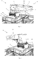
- a remotely operated vehicle 30 for the above automated storage and retrieval system 1 is disclosed.
- This vehicle 30 is a part of a vehicle assembly 10 shown in fig. 5 , which will be described in detail below.
- the main purpose of the vehicle assembly 10 is to perform a picking operation, i.e. to move one or several of the same type of product item, or to move several types of product items, from one or several storage containers 106 stored in the grid 104 to a target container 6.
- this vehicle assembly 10 may be referred to as a picking vehicle.
- This picking operation is typically performed based on a picking order, where one or several product items is picked, packaged into a shipping package and then sent to the address of the receiver who typically placed the picking order.
- the storage containers 106 and the target container 6 are of the same type.
- the remotely operated vehicle 30 comprises a vehicle body 31 and a wheel arrangement 32 connected to the vehicle body 31.
- the wheel arrangement is configured to move the remotely operated vehicle 30 along the rail system 108 of the automated storage and retrieval system 1.
- the vehicle 30 with its wheel arrangement 32 is considered prior art and will not be described herein detail.
- the vehicle body 31 comprises a carrier section 35 mounted to an upwardly facing surface 31a of the vehicle body 31 above the wheel arrangement 32.
- the vehicle 30 further comprises a container lifting device 50 configured to lift the target container 6.
- the container lifting device 50 is an open-top container lifting device 50, i.e. it has an access opening AO to the target container 6 from above.
- the container lifting device 50 comprises a container lifting frame 54 with a connection interface CI for connection to and disconnection from the target container 6.
- the container lifting device 50 is configured to lift the target container 6 to a height HI (see Fig. 1 ) above the top level of the grid 104 in order to carry the target container 6 during horizontal movement of the vehicle 30.
- this height HI is indicated as the vertical distance between the grid 104 and the lowermost part of the container 6'.
- the container container lifting device 50 is also configured to lower its connection interface into a grid column 105 of the grid 104 for connection to a target container 6 (for example an empty storage container 106 which are to be used as a new target container 6) or for storing the target container 6 temporarily in the grid.
- the container lifting device 50 comprises a frame section 51 and a housing section 52 connected to each other.
- the access opening AO to the target container 6 is defined through the frame section 51.
- the housing section 52 is connected to the carrier section 35 of the vehicle body 31.
- the frame section 51 here forms a cantilever type of structure, similar to the prior art vehicle 200, where a container lifting frame 54 is suspended below the frame section 51.
- Motors and other parts of the container lifting device 50 are located inside the frame section 51 and/or housing section 52. This enables the cross sectional area of the access opening AO in the frame section 51 to substantially equal to a cross sectional area of the access opening of the lifting frame 54 and/or the target container 6.
- the carrier section 35 comprises a lower carrier section 35a fixed to the upwardly facing surface 31a above the wheel arrangement 32 and an upper carrier section 35b connected to the housing section 52 of the container lifting device 50.
- the upper and lower carrier sections 35a, 35b are separated by a pivoting mechanism 36, allowing the upper carrier section 35b, and hence the container lifting device 50, to rotate in relation to the lower carrier section 35a.
- the upper carrier section 35b has been rotated 180° when compared to the embodiment of fig. 3 .
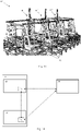
- the remotely operated vehicle assembly 10 is shown to comprise a first vehicle 30 and a second vehicle 30', which may either be of the type shown in fig. 3 or in fig. 4 .
- the vehicle assembly 10 comprises a bar system 60 which connects the vehicles 30, 30' of the vehicle assembly 10 to each other.
- the bar system 60 comprises a first bar 61 connected between the carrier sections 35 of the vehicles 30, 30'. It should be noted that the assembly 10 may move horizontally with respect to the grid by means of their wheel arrangements 32.
- the vehicle assembly 10 further comprises a picking system 40 for moving a product item 5 between the storage container 106 in the grid to one of the target containers 6, 6' carried by the first and second vehicle 30, 30'.
- the picking system 40 comprises a picking arm 41 having a first end 41a connected to the vehicle body 31 and a second end 41b connected to a holding mechanism 49 of the picking system 40.
- the picking arm 41 comprises several arm sections pivotably connected to each other.
- the picking arm 41 comprises a first arm section 42a pivotably connected to the bar 61 and a second arm section 42b axially displaceable with respect to the first arm section 42a, where the holding mechanism 49 is located in the end of the second arm section 42b.
- the first arm section 42a is pivotable with respect to the bar 61 around a first vertical axis I42a
- the second arm section 42b is axially displaceable with respect to the first arm section 42a along a second vertical axis I42b.
- each vehicle 30, 30' comprises a vehicle control system 34 provided in communication (indicated by dashed arrows) with each other and with other parts of the control system 20 of the automated storage and retrieval system 1.
- the wheel arrangements 32 of the two vehicles 30, 30' must be coordinated, as the vehicles must move in parallel when moving the assembly 10 in the Y-direction and move along a common line when moving the assembly 10 in the X-direction.
- picking arms with holding mechanisms are commercially available - and are considered prior art. Hence, the control of such picking arms with holding mechanism will not be described in detail herein.
- the holding mechanism 49 is configured to releasably hold the product item 5, and can use one of many known holding principles, such as by using a suction force provided by an air pump, a magnetic force provided by an electromagnet, a clamping force by using a claw operated by electric servo motors etc. It may use a combination of two or more of these holding principles.
- the picking system 40 may comprise object recognition equipment 48 (shown in fig. 4b) for recognizing the product item 5 in order to control the positioning of the picking arm and the holding mechanism 49 in relation to the product item 5 in order to hold it.
- the object recognition equipment 48 may also be used during release of the product item 5, for example in cases where the product items 5 are released into a shipping package (not shown) provided inside the target container 6.
- This shipping package may be a cardboard box, a rigid or semi-rigid bag, an envelope etc.
- the shipping package may be individually marked, in order for the picking system 40 to release the product item 5 into one specific shipping package of a plurality of shipping packages provided in the target container 6.
- the object recognition equipment 48 and the holding mechanism 49 should be selected based on the properties of the product items stored in the automated storage and retrieval system 1, such as size, weight, shape, color, packaging material etc.
- the storage containers 106 from which product items 5 is to be picked from must be positioned at a height in the grid 104 which is within reach of the picking system 40 of the assembly 10. This is typically performed by using container handling vehicles 200, 300 to stack storage containers 106 above each other to the desired height and then position the storage container 106 from which product items 5 is to be picked from, on top of the stack.
- Product items 5 located in storage containers 106 provided at the first and second levels, indicated in fig. 1 as levels z0 and z1, are typically within reach of the picking system 40.
- the position of the product item 5 that is to be picked may be referred to as an initial container position P0, which in fig. 5 is indicated to be the position of the storage container 106.
- the target container position P1 is the position of the target container 6 carried by the first vehicle 30.
- the vehicle assembly 10 is moved to a predetermined grid position GP1.
- the initial grid position GP1 is a position where the storage container 106 is within reach of the picking system 40, as shown in fig. 5 .
- the holding mechanism 49 is positioned in relation to the product item 5 in the storage container 106 by means of the picking arm 41 based on data from the object recognition equipment 48 and the holding mechanism 49 is subsequently activated to hold the product item 5.
- the picking arm 41 is then actuated to lift the product item 5 up from the storage container 106 and into the target container 6, where the holding mechanism 49 is deactivated to release the product item 5.
- the assembly 10 in fig. 5 has two target containers 6, 6'
- movement of the assembly may be reduced, as the same type of product items 5 can be picked from one storage container 106 and into both target containers, without moving the assembly 10 in relation to the grid - only the picking system 40 is moved.
- the assembly may leave the target container in the grid and start a new picking operation with a new target container.
- Other container handling vehicles may transport the target container to its final destination and may also supply the picking assembly with new target containers when needed.
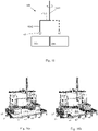
- the assembly 10 comprises four vehicles 30, 30', 30", 30′′′ of the type shown in fig. 3 provided in a rectangular configuration with each vehicle forming a corner of a rectangle.
- the target containers are not shown.
- the bar system 60 comprises a first bar 61 connecting the first and second vehicles 30, 30', a second bar 62 connecting the third and fourth vehicle 30", 30′′′ and a third bar 63 connecting the first and second bars 61, 62 to each other.
- the assembly 10 comprises one common picking system 40 of similar type to the one described above.
- the frame sections 51 of the first and third vehicles 30 are provided adjacent to, or in contact with each other, in order to prevent product items 5 falling into the grid in case the product item 5 becomes unintentionally released from the holding mechanism. If this happens, the product item will fall into one of the two target containers held by the vehicles 30, 30".
- the frame sections 51 of the second and fourth vehicles are arranged in similar manner.
- the assembly 10 further comprises a cover system 70 for preventing the product item falling into the grid 104.
- the cover system comprises cover sections 71, 72 connected between the vehicles, where the cover sections 71 and 72 prevent product items unintentionally falling into the grid 104 in the event that a product item becomes unintentionally released from the holding mechanism.
- the cover system 70 further comprises a door 75 which in its closed state prevents the product item falling into the grid 104 and which in its open state allows access for the holding mechanism 49 to a storage container 106 stored in the grid 104 below the door 75.
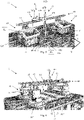
- the carrier section 35 comprises a rigid tower structure fixed to the top surface TS of the vehicle body 31.
- the carrier section 35 has a vertical plate structure 37 provided adjacent to, or aligned with, a front surface FS of the vehicle body 31.
- the container lifting device 50 comprises a container lifting frame 54 with its connection interface CI fixed to the lower end of the container lifting frame 54, similar to the embodiment above.
- the container lifting frame 54 is also here axially displaceable up and down with respect to the carrier section 35.
- the container lifting frame 54 is not suspended below a lifting frame 51; the container lifting frame 54 is here fixed to a supporting structure 56 extending vertically.
- the container lifting device 54 and the supporting structure 56 forms a rigid structure which is adapted to be at least partially lowered into a cell of the grid 104 in order to pick up or put away a target container 6.
- the supporting structure 56 is connected to the vertical plate structure 37 by means of a lifting mechanism 57, where one part of the lifting mechanism 57 is fixed to the plate structure 37 and another part of the lifting mechanism 57 is fixed to a side of the supporting structure 56 facing towards the plate structure 57.
- the lifting mechanism 57 may be an electric servo motor, an electric linear motor etc.
- Figs. 8 and 9 show how the target container 6 can be elevated and lowered with respect to the grid.
- a vehicle assembly 10 comprising two vehicles 30, 30' is shown.
- the vehicle assembly 10 comprises a bar system 60 with a bar 61 connected between the carrier sections 35.
- An additional bar element 61a is connected between the carrier sections 35.
- the picking arm 41 of the picking system 40 here comprises a first arm section 42a axially displaceable with respect to the bar 61 along a first, horizontal axis I42a, a second arm section 42b axially displaceable with respect to the first arm section 42a along a second, vertical axis I42b and a third arm section 42c pivotably connected to the second arm section 42b around a third, vertical axis I42c.
- the third arm section 42c comprises a first arm element 42c1 and a second arm element 42c2 oriented in parallel with each other, where a third arm element 42c3 is connecting the first arm element 42c1 with the second arm element 42c2.
- the first arm element is located above the second arm element.
- the first and second arm elements are oriented in a vertical direction.
- the third arm element 42c3 is oriented horizontally.
- the first arm element 41c1 is pivotably connected to the second arm section 42b.
- the holding device 49 is connected to the lower end of the second arm element.
- the footprint i.e. the extent in x- and y-direction
- a footprint area FA being two cells long in the y-direction (y1, y1) and four items cells wide in the x-direction (x1, x2, x3, x4), i.e. a total of eight cells.
- y1, y1 the footprint area
- x1, x2, x3, x4 the cells below the vehicles 30 and below the target containers 6 are a part of this footprint area FA.
- a picking area PA is defined to be the area between the vehicles and storage containers, i.e. two cells long in the y-direction (y1, y1) and two cells wide in the x-direction (x2, x3).
- the vehicle assembly 10 comprises four vehicles 30, 30', 30", 30′′′ in a rectangular configuration, similar to fig. 6 .
- the bar system 60 comprises a first bar 61 connecting the first and second vehicles 30, 30', a second bar 62 connecting the third and fourth vehicle 30", 30′′′, a third bar 63 connecting the first and third vehicles 30, 30" to each other and a fourth bar 64 connecting the second and fourth vehicles 30', 30′′′ to each other.
- the first and second bars are parallel to each other and the third and fourth bars are parallel to each other.
- the picking system 40 is similar to the picking system 40 of fig. 10 . However, here, the first arm section 42a is axially displaceable with respect to a fifth bar 65, which itself is axially displaceable with respect to the first and second bars 61, 62.
- the assembly 10 comprises a cover system 70, as described above with respect to fig. 6 .
- the vehicle assembly comprises eight vehicles 30 and a picking system 40 with three picking arms 41, 41', 41".
- picking orders may be performed in parallel, as picking is performed to several target containers at the same time.
- that container lifting device 50 may leave the target container in the grid and retrieve a new empty target container for new product orders.
- Other container handing vehicles will transport the target container to its final destination and may also supply the picking vehicle with new target containers when needed.
Landscapes
- Engineering & Computer Science (AREA)
- Mechanical Engineering (AREA)
- Transportation (AREA)
- Structural Engineering (AREA)
- Civil Engineering (AREA)
- Life Sciences & Earth Sciences (AREA)
- Geology (AREA)
- Physics & Mathematics (AREA)
- Mathematical Physics (AREA)
- Warehouses Or Storage Devices (AREA)
- Automobile Manufacture Line, Endless Track Vehicle, Trailer (AREA)
- Automatic Assembly (AREA)
Claims (16)
- Ensemble de véhicules télécommandés (10) pour un système de stockage et de récupération automatisé (1) pour déplacer un article de produit (5) entre un contenant de stockage (106) stocké dans une grille de stockage et de récupération automatisée (104) configurée pour stocker une pluralité de piles (107) de contenants de stockage (106), et des contenants cibles (6) ; dans lequel l'ensemble de véhicules télécommandés (10) comprend :- un premier véhicule (30) comprenant une carrosserie de véhicule (31) et un agencement de roues (32) connecté à la carrosserie de véhicule (31) configuré pour déplacer le véhicule télécommandé (30) le long d'un système de rails (108) du système de stockage et de récupération automatisé (1) ;- où le premier véhicule (30) comprend un dispositif de levage de contenant (50) configuré pour porter un premier contenant cible (6) ;- un système de prélèvement (40) pour déplacer l'article de produit (5) ;caractérisé en ce que :- l'ensemble de véhicules (10) comprend en outre un deuxième véhicule (30') comprenant une carrosserie de véhicule (31) et un agencement de roues (32) connecté à la carrosserie de véhicule (31) configuré pour déplacer le véhicule télécommandé (30) le long d'un système de rails (108) du système de stockage et de récupération automatisé (1) ;- le deuxième véhicule (30') comprend un dispositif de levage de contenant (50) configuré pour porter un deuxième contenant cible (6') ;- un système de barre (60) connectant mécaniquement les véhicules (30, 30') de l'ensemble de véhicules (10) les uns aux autres ;- le système de prélèvement (40) est connecté au système de barre (60) ;- le système de prélèvement (40) est configuré pour déplacer l'article de produit (5) du contenant de stockage (106) à l'un du premier ou du deuxième contenant cible (6, 6').
- Ensemble de véhicules télécommandés (10) selon la revendication 1, où le système de prélèvement est positionné entre les premier et deuxième véhicules (30, 30').
- Ensemble de véhicules télécommandés (10) selon l'une quelconque des revendications précédentes, où chaque véhicule (30, 30') comprend un système de commande (34) prévu en communication avec les systèmes de commande (34) d'autres véhicules et en communication avec un système de commande (20) du système de stockage et de récupération automatisé (1).
- Ensemble de véhicules télécommandés (10) selon l'une quelconque des revendications précédentes, où l'ensemble (10) comprend un troisième véhicule (30") et un quatrième véhicule (30‴), où le système de barre (60) est mécaniquement connecté aux quatre véhicules (30, 30', 30", 30‴) de l'ensemble de véhicules (10), où les quatre véhicules ensemble sont prévus dans une configuration rectangulaire.
- Ensemble de véhicules télécommandés (10) selon l'une quelconque des revendications précédentes, où le système de prélèvement (40) comprend un premier bras de prélèvement (41) avec un mécanisme de maintien (49), où une première extrémité (41a) du premier bras de prélèvement (41) est connectée au système de barre (60) et une deuxième extrémité (41b) du premier bras de prélèvement (41) est connectée au mécanisme de maintien (49).
- Ensemble de véhicules télécommandés (10) selon la revendication 5, où le premier bras de prélèvement (41) comprend une première section de bras (42a) connectée pivotante au système de barre (60) et une deuxième section de bras (42b) pouvant être déplacée axialement par rapport à la première section de bras (42a).
- Ensemble de véhicules télécommandés (10) selon l'une quelconque des revendications précédentes, où le système de prélèvement (40) comprend un deuxième bras de prélèvement (41') avec un mécanisme de maintien (49), où une première extrémité (41a) du deuxième bras de prélèvement (41') est connectée au système de barre (60) et une deuxième extrémité (41b) du deuxième bras de prélèvement (41') est connectée à son mécanisme de maintien (49).
- Ensemble de véhicules télécommandés (10) selon l'une quelconque des revendications précédentes, où l'ensemble (10) comprend un système de couvercle (70) pour empêcher l'article de produit de tomber dans la grille (104).
- Ensemble de véhicules télécommandés (10) selon la revendication 9, où le système de couvercle (70) comprend une porte (75) qui dans son état fermé empêche l'article de produit de tomber dans la grille (104) et qui dans son état ouvert permet l'accès, pour le mécanisme de maintien (49), à un contenant de stockage (106) stocké dans la grille 104 sous la porte (75).
- Ensemble de véhicules télécommandés (10) selon l'une quelconque des revendications précédentes, où le dispositif de levage de contenant (50) est un dispositif de levage de contenant (50) à partie supérieure ouverte.
- Ensemble de véhicules télécommandés (10) selon l'une quelconque des revendications précédentes, où le dispositif de levage de contenant (50) est configuré pour soulever le contenant cible (6) à une hauteur (H1) au-dessus du niveau supérieur de la grille (104).
- Ensemble de véhicules télécommandés (10) selon l'une quelconque des revendications précédentes, où le dispositif de levage de contenant (50) est configuré pour abaisser le contenant cible (6) dans une colonne de grille (105) de la grille (104).
- Ensemble de véhicules télécommandés (30) selon l'une quelconque des revendications précédentes, où le dispositif de levage de contenant (50) est agencé sous la forme d'une structure en porte-à-faux (51) fixée à la carrosserie de véhicule (31), où le dispositif de levage de contenant (50) comprend un cadre de levage de contenant (54) avec une interface de connexion CI pour une connexion à et une déconnexion du contenant cible 6 prévues sous la structure en porte-à-faux.
- Ensemble de véhicules télécommandés (30) selon l'une quelconque des revendications 1 à 12 précédentes, où :- le véhicule (30) comprend une section de transport (35) avec une structure de plaque verticale (37) prévue adjacente à une surface avant (FS) de la carrosserie de véhicule (31) ;- le dispositif de levage de contenant (50) comprend un cadre de levage de contenant (54) fixé à une structure de support (56) verticale ;- la structure de support (56) est connectée à la structure de plaque verticale (37) au moyen d'un mécanisme de levage (57) pour abaisser le dispositif de levage de contenant (54) et la structure de support (56) au moins partiellement dans une cellule de la grille (104).
- Procédé pour déplacer un article de produit (5) entre un contenant de stockage (106) stocké dans une grille de stockage et de récupération automatisée (104) d'un système de stockage et de récupération automatisé (1), où la grille (104) est configurée pour stocker une pluralité de piles (107) de contenants de stockage (106), et un contenant supplémentaire (6), où le procédé comprend les étapes de :- prévision d'un ensemble de véhicules (10) par connexion d'un premier véhicule (30) à un deuxième véhicule (30') au moyen d'un système de barre (60), les premier et deuxième véhicules (30, 30') comprenant chacun une carrosserie (31) et un agencement de roues connecté à la carrosserie de véhicule (31) et un dispositif de levage de contenant (50) ;- connexion d'un système de prélèvement (40) au système de barre (60), où le système de prélèvement (40) comprend un mécanisme de maintien (49) et un bras de prélèvement (41) où le bras de prélèvement (41) a une première extrémité (41a) connectée au système de barre (60) et une deuxième extrémité (41b) connectée au mécanisme de maintien (49) ;- déplacement de l'ensemble de véhicules (10) le long d'un système de rails (108) du système de stockage et de récupération automatisé (1) jusqu'à une position de grille prédéterminée (GP1) ;- commande du système de prélèvement (40) pour maintenir l'article de produit (5) étant situé au niveau d'une position de contenant initiale (P0),- commande du système de prélèvement (40) pour déplacer l'article de produit (5) jusqu'à une position de contenant cible (P1) et pour libérer l'article de produit (5) à la position de contenant cible (P1).
- Système de stockage et de récupération automatisé (1) comprenant :- une grille de stockage et de récupération automatisée (104) configurée pour stocker une pluralité de piles (107) de contenants de stockage (106) ;- un ensemble de véhicules (10) selon l'une quelconque des revendications 1 à 14.
Applications Claiming Priority (2)
| Application Number | Priority Date | Filing Date | Title |
|---|---|---|---|
| NO20181418A NO344971B1 (en) | 2018-11-06 | 2018-11-06 | Robot vehicle assembly with picking system |
| PCT/EP2019/077739 WO2020094336A1 (fr) | 2018-11-06 | 2019-10-14 | Système de stockage et de récupération automatisé |
Publications (2)
| Publication Number | Publication Date |
|---|---|
| EP3877296A1 EP3877296A1 (fr) | 2021-09-15 |
| EP3877296B1 true EP3877296B1 (fr) | 2022-11-30 |
Family
ID=68289940
Family Applications (1)
| Application Number | Title | Priority Date | Filing Date |
|---|---|---|---|
| EP19789907.3A Active EP3877296B1 (fr) | 2018-11-06 | 2019-10-14 | Système de stockage et de récupération automatisé |
Country Status (6)
| Country | Link |
|---|---|
| US (1) | US11383926B2 (fr) |
| EP (1) | EP3877296B1 (fr) |
| CN (1) | CN112969650B (fr) |
| NO (1) | NO344971B1 (fr) |
| PL (1) | PL3877296T3 (fr) |
| WO (1) | WO2020094336A1 (fr) |
Families Citing this family (18)
| Publication number | Priority date | Publication date | Assignee | Title |
|---|---|---|---|---|
| USD934324S1 (en) * | 2019-06-17 | 2021-10-26 | Autostore Technology AS | Autonomous transport robot |
| US11724880B2 (en) | 2019-07-29 | 2023-08-15 | Nimble Robotics, Inc. | Storage systems and methods for robotic picking |
| US11738447B2 (en) | 2019-07-29 | 2023-08-29 | Nimble Robotics, Inc. | Storage systems and methods for robotic picking |
| AU2021211415A1 (en) | 2020-01-22 | 2022-08-25 | Energy Vault, Inc. | Grabber comprising a damped self-centering mechanism |
| NO346266B1 (en) * | 2020-05-25 | 2022-05-16 | Autostore Tech As | Container handling vehicle for lifting a storage container and method of receiving a target storage container from a storage system |
| BR112022026870A2 (pt) | 2020-06-30 | 2023-01-24 | Energy Vault Inc | Sistema e método de armazenamento e entrega de energia |
| NO346409B1 (en) * | 2020-11-30 | 2022-07-11 | Autostore Tech As | A vehicle for transporting storage containers in an automated storage and retrieval system |
| JP2024504739A (ja) | 2021-02-02 | 2024-02-01 | エナジー ヴォールト インコーポレイテッド | エレベーターリフトシステムを備えたエネルギー貯蔵システム |
| EP4347449A2 (fr) * | 2021-06-02 | 2024-04-10 | Nimble Robotics, Inc. | Systèmes de stockage et robots de ramassage et de placement |
| CN113460550B (zh) * | 2021-06-30 | 2022-11-29 | 三一建筑机器人(西安)研究院有限公司 | 货物拣选系统及拣选方法 |
| DE102021132413B3 (de) | 2021-12-09 | 2023-05-11 | Ssi Schäfer Automation Gmbh (At) | Kommissionier-Shuttle und Verfahren zum Kommissionieren innerhalb einer Shuttle-Regalgasse |
| CN116262588A (zh) | 2021-12-13 | 2023-06-16 | 能源库公司 | 能量储存和输送系统及方法 |
| CN114368576B (zh) * | 2022-01-29 | 2022-11-04 | 上海方仓智能科技有限公司 | 一种非货架式全自动库房 |
| EP4230549A1 (fr) * | 2022-02-16 | 2023-08-23 | VOLUME Lagersysteme GmbH | Système d'entrepôt pour agencement tridimensionnel de bacs de stockage |
| WO2024074619A1 (fr) * | 2022-10-05 | 2024-04-11 | Volume Lagersysteme Gmbh | Véhicule pouvant être utilisé dans un système d'entrepôt |
| EP4349740A1 (fr) * | 2022-10-05 | 2024-04-10 | VOLUME Lagersysteme GmbH | Véhicule pour lever des bacs de stockage dans un entrepôt |
| WO2024074615A1 (fr) * | 2022-10-05 | 2024-04-11 | Volume Lagersysteme Gmbh | Véhicule pouvant être utilisé dans un système d'entrepôt |
| US20240140494A1 (en) | 2023-04-10 | 2024-05-02 | Energy Vault, Inc. | Energy storage and delivery system and method |
Family Cites Families (19)
| Publication number | Priority date | Publication date | Assignee | Title |
|---|---|---|---|---|
| NO317366B1 (no) | 1999-07-01 | 2004-10-18 | Autostore As | Lagringsanlegg med fjernstyrte vogner med to hjulsett og heisinnretning for drift på skinner anlagt i kryss over kolonner av lagringsenheter som er adskilt med vertikale profilstolper |
| NO334806B1 (no) | 2012-11-13 | 2014-06-02 | Jakob Hatteland Logistics As | Lagringssystem |
| NO335839B1 (no) | 2012-12-10 | 2015-03-02 | Jakob Hatteland Logistics As | Robot for transport av lagringsbeholdere |
| GB201404870D0 (en) * | 2014-03-18 | 2014-04-30 | Ocado Ltd | Robotic service device and handling method |
| GB201314313D0 (en) * | 2013-08-09 | 2013-09-25 | Ocado Ltd | Apparatus for retrieving units from a storage system |
| US20150098775A1 (en) * | 2013-10-09 | 2015-04-09 | Sergey N. Razumov | Automatic order picking system and method in retail facility |
| NO340313B1 (no) * | 2014-01-08 | 2017-03-27 | Jakob Hatteland Logistics As | Fjernstyrt kjøretøy for å plukke opp lagringsbeholdere fra et lagringssystem, lagringssystem for lagring av beholdere og fremgangsmåte for å bytte en strømkilde |
| HU230618B1 (hu) * | 2014-04-07 | 2017-04-28 | Antal Zombori | Raktári árukezelő rendszer és rakodó-berendezés raktári árukezelő rendszerhez |
| NO337544B1 (no) * | 2014-06-19 | 2016-05-02 | Jakob Hatteland Logistics As | Fjernstyrt kjøretøysammenstilling for å plukke opp lagringsbeholdere fra et lagringssystem |
| EP3209583B1 (fr) * | 2014-10-20 | 2020-06-24 | Nelson Mandela Metropolitan University | Système de rangement |
| US9821958B2 (en) * | 2014-12-22 | 2017-11-21 | Oracle International Corporation | System for simultaneous pivoting and translation of robot arm of storage library |
| GB201509921D0 (en) | 2015-06-08 | 2015-07-22 | Ocado Innovation Ltd | Object storage, handling and retrieving system and method |
| HUE057843T2 (hu) * | 2015-04-27 | 2022-06-28 | Attabotics Inc | Tároló és visszakeresõ rendszer |
| NO339783B1 (en) | 2015-06-11 | 2017-01-30 | Jakob Hatteland Logistics As | Storage system |
| US10899539B2 (en) | 2015-11-11 | 2021-01-26 | Ocado Innovation Limited | Picking systems and methods |
| NO20160118A1 (en) * | 2016-01-26 | 2017-07-27 | Autostore Tech As | Remotely operated vehicle |
| GB201604100D0 (en) * | 2016-03-10 | 2016-04-20 | Ocado Innovation Ltd | Apparatus for retrieving units from a storage system |
| DE102017121638A1 (de) * | 2017-09-19 | 2019-03-21 | Heron Sondermaschinen Und Steuerungen Gmbh | Schienengebundener Transportroboter mit Hubplattform |
| JP7147851B2 (ja) * | 2018-08-06 | 2022-10-05 | 村田機械株式会社 | 自動倉庫、及び、搬送装置 |
-
2018
- 2018-11-06 NO NO20181418A patent/NO344971B1/no unknown
-
2019
- 2019-10-14 US US17/291,483 patent/US11383926B2/en active Active
- 2019-10-14 EP EP19789907.3A patent/EP3877296B1/fr active Active
- 2019-10-14 WO PCT/EP2019/077739 patent/WO2020094336A1/fr unknown
- 2019-10-14 CN CN201980071149.XA patent/CN112969650B/zh active Active
- 2019-10-14 PL PL19789907.3T patent/PL3877296T3/pl unknown
Also Published As
| Publication number | Publication date |
|---|---|
| PL3877296T3 (pl) | 2023-03-13 |
| EP3877296A1 (fr) | 2021-09-15 |
| US20220002077A1 (en) | 2022-01-06 |
| CN112969650B (zh) | 2022-10-14 |
| CN112969650A (zh) | 2021-06-15 |
| WO2020094336A1 (fr) | 2020-05-14 |
| NO20181418A1 (en) | 2020-05-07 |
| US11383926B2 (en) | 2022-07-12 |
| NO344971B1 (en) | 2020-08-03 |
Similar Documents
| Publication | Publication Date | Title |
|---|---|---|
| EP3877296B1 (fr) | Système de stockage et de récupération automatisé | |
| US20220073279A1 (en) | Remotely operated vehicle for an automated storage and retrieval system | |
| EP3653538B1 (fr) | Véhicule de transport et installation de transport | |
| CN111776562B (zh) | 存储容器、箱和设备 | |
| NO344750B1 (en) | Unloading arrangement and unloading station, as well as method of unloading an item from a storage container | |
| EP3887293B1 (fr) | Conteneur de stockage pour système automatisé de stockage et de récupération | |
| US11603107B2 (en) | Unloading arrangement and unloading station, as well as method of unloading an item from a storage container | |
| US20240043045A1 (en) | Container accessing station with lifting device | |
| CN115151495A (zh) | 输送机系统 | |
| WO2019238642A1 (fr) | Agencement de déchargement et poste de déchargement, ainsi que procédé de déchargement d'un article à partir d'un conteneur de stockage | |
| US11485375B2 (en) | Unloading arrangement and unloading station, as well as method of unloading an item from a storage container | |
| US20230278753A1 (en) | Storage container for automated storage and retrieval system | |
| JP2024026404A (ja) | 荷下ろし構成体および荷下ろしステーション、ならびに、保管コンテナからアイテムを降ろす方法 | |
| CN117957178A (zh) | 容器缓冲组件、包括该容器缓冲组件的储存系统及相关方法 | |
| CA3117120A1 (fr) | Conteneur de stockage pour systeme automatise de stockage et de recuperation |
Legal Events
| Date | Code | Title | Description |
|---|---|---|---|
| STAA | Information on the status of an ep patent application or granted ep patent |
Free format text: STATUS: UNKNOWN |
|
| STAA | Information on the status of an ep patent application or granted ep patent |
Free format text: STATUS: THE INTERNATIONAL PUBLICATION HAS BEEN MADE |
|
| PUAI | Public reference made under article 153(3) epc to a published international application that has entered the european phase |
Free format text: ORIGINAL CODE: 0009012 |
|
| STAA | Information on the status of an ep patent application or granted ep patent |
Free format text: STATUS: REQUEST FOR EXAMINATION WAS MADE |
|
| 17P | Request for examination filed |
Effective date: 20210507 |
|
| AK | Designated contracting states |
Kind code of ref document: A1 Designated state(s): AL AT BE BG CH CY CZ DE DK EE ES FI FR GB GR HR HU IE IS IT LI LT LU LV MC MK MT NL NO PL PT RO RS SE SI SK SM TR |
|
| DAV | Request for validation of the european patent (deleted) | ||
| DAX | Request for extension of the european patent (deleted) | ||
| GRAP | Despatch of communication of intention to grant a patent |
Free format text: ORIGINAL CODE: EPIDOSNIGR1 |
|
| STAA | Information on the status of an ep patent application or granted ep patent |
Free format text: STATUS: GRANT OF PATENT IS INTENDED |
|
| INTG | Intention to grant announced |
Effective date: 20220704 |
|
| GRAS | Grant fee paid |
Free format text: ORIGINAL CODE: EPIDOSNIGR3 |
|
| GRAA | (expected) grant |
Free format text: ORIGINAL CODE: 0009210 |
|
| STAA | Information on the status of an ep patent application or granted ep patent |
Free format text: STATUS: THE PATENT HAS BEEN GRANTED |
|
| AK | Designated contracting states |
Kind code of ref document: B1 Designated state(s): AL AT BE BG CH CY CZ DE DK EE ES FI FR GB GR HR HU IE IS IT LI LT LU LV MC MK MT NL NO PL PT RO RS SE SI SK SM TR |
|
| REG | Reference to a national code |
Ref country code: CH Ref legal event code: EP Ref country code: GB Ref legal event code: FG4D |
|
| REG | Reference to a national code |
Ref country code: AT Ref legal event code: REF Ref document number: 1534537 Country of ref document: AT Kind code of ref document: T Effective date: 20221215 Ref country code: DE Ref legal event code: R096 Ref document number: 602019022614 Country of ref document: DE |
|
| REG | Reference to a national code |
Ref country code: IE Ref legal event code: FG4D |
|
| REG | Reference to a national code |
Ref country code: LT Ref legal event code: MG9D |
|
| REG | Reference to a national code |
Ref country code: NL Ref legal event code: MP Effective date: 20221130 |
|
| PG25 | Lapsed in a contracting state [announced via postgrant information from national office to epo] |
Ref country code: SE Free format text: LAPSE BECAUSE OF FAILURE TO SUBMIT A TRANSLATION OF THE DESCRIPTION OR TO PAY THE FEE WITHIN THE PRESCRIBED TIME-LIMIT Effective date: 20221130 Ref country code: PT Free format text: LAPSE BECAUSE OF FAILURE TO SUBMIT A TRANSLATION OF THE DESCRIPTION OR TO PAY THE FEE WITHIN THE PRESCRIBED TIME-LIMIT Effective date: 20230331 Ref country code: NO Free format text: LAPSE BECAUSE OF FAILURE TO SUBMIT A TRANSLATION OF THE DESCRIPTION OR TO PAY THE FEE WITHIN THE PRESCRIBED TIME-LIMIT Effective date: 20230228 Ref country code: LT Free format text: LAPSE BECAUSE OF FAILURE TO SUBMIT A TRANSLATION OF THE DESCRIPTION OR TO PAY THE FEE WITHIN THE PRESCRIBED TIME-LIMIT Effective date: 20221130 Ref country code: FI Free format text: LAPSE BECAUSE OF FAILURE TO SUBMIT A TRANSLATION OF THE DESCRIPTION OR TO PAY THE FEE WITHIN THE PRESCRIBED TIME-LIMIT Effective date: 20221130 Ref country code: ES Free format text: LAPSE BECAUSE OF FAILURE TO SUBMIT A TRANSLATION OF THE DESCRIPTION OR TO PAY THE FEE WITHIN THE PRESCRIBED TIME-LIMIT Effective date: 20221130 |
|
| REG | Reference to a national code |
Ref country code: AT Ref legal event code: MK05 Ref document number: 1534537 Country of ref document: AT Kind code of ref document: T Effective date: 20221130 |
|
| PG25 | Lapsed in a contracting state [announced via postgrant information from national office to epo] |
Ref country code: RS Free format text: LAPSE BECAUSE OF FAILURE TO SUBMIT A TRANSLATION OF THE DESCRIPTION OR TO PAY THE FEE WITHIN THE PRESCRIBED TIME-LIMIT Effective date: 20221130 Ref country code: LV Free format text: LAPSE BECAUSE OF FAILURE TO SUBMIT A TRANSLATION OF THE DESCRIPTION OR TO PAY THE FEE WITHIN THE PRESCRIBED TIME-LIMIT Effective date: 20221130 Ref country code: IS Free format text: LAPSE BECAUSE OF FAILURE TO SUBMIT A TRANSLATION OF THE DESCRIPTION OR TO PAY THE FEE WITHIN THE PRESCRIBED TIME-LIMIT Effective date: 20230330 Ref country code: HR Free format text: LAPSE BECAUSE OF FAILURE TO SUBMIT A TRANSLATION OF THE DESCRIPTION OR TO PAY THE FEE WITHIN THE PRESCRIBED TIME-LIMIT Effective date: 20221130 Ref country code: GR Free format text: LAPSE BECAUSE OF FAILURE TO SUBMIT A TRANSLATION OF THE DESCRIPTION OR TO PAY THE FEE WITHIN THE PRESCRIBED TIME-LIMIT Effective date: 20230301 |
|
| P01 | Opt-out of the competence of the unified patent court (upc) registered |
Effective date: 20230524 |
|
| PG25 | Lapsed in a contracting state [announced via postgrant information from national office to epo] |
Ref country code: NL Free format text: LAPSE BECAUSE OF FAILURE TO SUBMIT A TRANSLATION OF THE DESCRIPTION OR TO PAY THE FEE WITHIN THE PRESCRIBED TIME-LIMIT Effective date: 20221130 |
|
| PG25 | Lapsed in a contracting state [announced via postgrant information from national office to epo] |
Ref country code: SM Free format text: LAPSE BECAUSE OF FAILURE TO SUBMIT A TRANSLATION OF THE DESCRIPTION OR TO PAY THE FEE WITHIN THE PRESCRIBED TIME-LIMIT Effective date: 20221130 Ref country code: RO Free format text: LAPSE BECAUSE OF FAILURE TO SUBMIT A TRANSLATION OF THE DESCRIPTION OR TO PAY THE FEE WITHIN THE PRESCRIBED TIME-LIMIT Effective date: 20221130 Ref country code: EE Free format text: LAPSE BECAUSE OF FAILURE TO SUBMIT A TRANSLATION OF THE DESCRIPTION OR TO PAY THE FEE WITHIN THE PRESCRIBED TIME-LIMIT Effective date: 20221130 Ref country code: DK Free format text: LAPSE BECAUSE OF FAILURE TO SUBMIT A TRANSLATION OF THE DESCRIPTION OR TO PAY THE FEE WITHIN THE PRESCRIBED TIME-LIMIT Effective date: 20221130 Ref country code: CZ Free format text: LAPSE BECAUSE OF FAILURE TO SUBMIT A TRANSLATION OF THE DESCRIPTION OR TO PAY THE FEE WITHIN THE PRESCRIBED TIME-LIMIT Effective date: 20221130 Ref country code: AT Free format text: LAPSE BECAUSE OF FAILURE TO SUBMIT A TRANSLATION OF THE DESCRIPTION OR TO PAY THE FEE WITHIN THE PRESCRIBED TIME-LIMIT Effective date: 20221130 |
|
| PG25 | Lapsed in a contracting state [announced via postgrant information from national office to epo] |
Ref country code: SK Free format text: LAPSE BECAUSE OF FAILURE TO SUBMIT A TRANSLATION OF THE DESCRIPTION OR TO PAY THE FEE WITHIN THE PRESCRIBED TIME-LIMIT Effective date: 20221130 Ref country code: AL Free format text: LAPSE BECAUSE OF FAILURE TO SUBMIT A TRANSLATION OF THE DESCRIPTION OR TO PAY THE FEE WITHIN THE PRESCRIBED TIME-LIMIT Effective date: 20221130 |
|
| REG | Reference to a national code |
Ref country code: DE Ref legal event code: R097 Ref document number: 602019022614 Country of ref document: DE |
|
| PLBE | No opposition filed within time limit |
Free format text: ORIGINAL CODE: 0009261 |
|
| STAA | Information on the status of an ep patent application or granted ep patent |
Free format text: STATUS: NO OPPOSITION FILED WITHIN TIME LIMIT |
|
| PGFP | Annual fee paid to national office [announced via postgrant information from national office to epo] |
Ref country code: GB Payment date: 20230911 Year of fee payment: 5 |
|
| 26N | No opposition filed |
Effective date: 20230831 |
|
| REG | Reference to a national code |
Ref country code: GB Ref legal event code: 732E Free format text: REGISTERED BETWEEN 20231019 AND 20231025 |
|
| PG25 | Lapsed in a contracting state [announced via postgrant information from national office to epo] |
Ref country code: SI Free format text: LAPSE BECAUSE OF FAILURE TO SUBMIT A TRANSLATION OF THE DESCRIPTION OR TO PAY THE FEE WITHIN THE PRESCRIBED TIME-LIMIT Effective date: 20221130 |
|
| PGFP | Annual fee paid to national office [announced via postgrant information from national office to epo] |
Ref country code: PL Payment date: 20230816 Year of fee payment: 5 |