EP3877293B1 - Adapter und spender mit einem adapter - Google Patents
Adapter und spender mit einem adapter Download PDFInfo
- Publication number
- EP3877293B1 EP3877293B1 EP19804861.3A EP19804861A EP3877293B1 EP 3877293 B1 EP3877293 B1 EP 3877293B1 EP 19804861 A EP19804861 A EP 19804861A EP 3877293 B1 EP3877293 B1 EP 3877293B1
- Authority
- EP
- European Patent Office
- Prior art keywords
- adapter
- foam component
- hole
- foam
- fluid
- Prior art date
- Legal status (The legal status is an assumption and is not a legal conclusion. Google has not performed a legal analysis and makes no representation as to the accuracy of the status listed.)
- Active
Links
Images


Classifications
-
- B—PERFORMING OPERATIONS; TRANSPORTING
- B65—CONVEYING; PACKING; STORING; HANDLING THIN OR FILAMENTARY MATERIAL
- B65D—CONTAINERS FOR STORAGE OR TRANSPORT OF ARTICLES OR MATERIALS, e.g. BAGS, BARRELS, BOTTLES, BOXES, CANS, CARTONS, CRATES, DRUMS, JARS, TANKS, HOPPERS, FORWARDING CONTAINERS; ACCESSORIES, CLOSURES, OR FITTINGS THEREFOR; PACKAGING ELEMENTS; PACKAGES
- B65D83/00—Containers or packages with special means for dispensing contents
- B65D83/14—Containers for dispensing liquid or semi-liquid contents by internal gaseous pressure, i.e. aerosol containers comprising propellant
- B65D83/32—Dip-tubes
-
- B—PERFORMING OPERATIONS; TRANSPORTING
- B05—SPRAYING OR ATOMISING IN GENERAL; APPLYING FLUENT MATERIALS TO SURFACES, IN GENERAL
- B05B—SPRAYING APPARATUS; ATOMISING APPARATUS; NOZZLES
- B05B11/00—Single-unit hand-held apparatus in which flow of contents is produced by the muscular force of the operator at the moment of use
- B05B11/0005—Components or details
- B05B11/0089—Dispensing tubes
-
- B—PERFORMING OPERATIONS; TRANSPORTING
- B05—SPRAYING OR ATOMISING IN GENERAL; APPLYING FLUENT MATERIALS TO SURFACES, IN GENERAL
- B05B—SPRAYING APPARATUS; ATOMISING APPARATUS; NOZZLES
- B05B15/00—Details of spraying plant or spraying apparatus not otherwise provided for; Accessories
- B05B15/40—Filters located upstream of the spraying outlets
-
- B—PERFORMING OPERATIONS; TRANSPORTING
- B65—CONVEYING; PACKING; STORING; HANDLING THIN OR FILAMENTARY MATERIAL
- B65D—CONTAINERS FOR STORAGE OR TRANSPORT OF ARTICLES OR MATERIALS, e.g. BAGS, BARRELS, BOTTLES, BOXES, CANS, CARTONS, CRATES, DRUMS, JARS, TANKS, HOPPERS, FORWARDING CONTAINERS; ACCESSORIES, CLOSURES, OR FITTINGS THEREFOR; PACKAGING ELEMENTS; PACKAGES
- B65D83/00—Containers or packages with special means for dispensing contents
- B65D83/14—Containers for dispensing liquid or semi-liquid contents by internal gaseous pressure, i.e. aerosol containers comprising propellant
- B65D83/75—Aerosol containers not provided for in groups B65D83/16 - B65D83/74
- B65D83/754—Aerosol containers not provided for in groups B65D83/16 - B65D83/74 comprising filters in the fluid flow path
Definitions
- the present disclosure generally relates to dispensers and dispensers with dip tubes and/or adapters, including dispensers that have an adapter and are suitable for aerosol applications.
- Dispensers such as pressurized dispensers or containers for aerosol applications, may include a body or shell, a valve, and a dip tube that may extend from the valve to the product or contents within the body or shell.
- some dispensers include a foam component.
- some dispensers include a foamed or cellular material.
- the disclosure of U.S. Patent 10,077,150 is incorporated herein by reference in its entirety.
- Common nozzle arrangements may include an inlet, an outlet through which a fluid may be dispensed to an external environment, and an internal flow passageway through which fluid can flow from the inlet to the outlet.
- Nozzle arrangements may additionally include an actuator - such as a manually operated pump or trigger or aerosol canister. Operation of the actuator can cause fluid to flow into the inlet of the arrangement, along the flow passageway, and on to the outlet.
- a number of manually operated aerosol cans, pumps, or triggers may have a dip tube, which may extend, for example, from a top or outlet of a container to the bottom of the container, so as to draw fluid from the bottom to the top.
- Some dip tubes may be part of a container and may be centered or along a wall of a container.
- the GB 2 356 674 A discloses a cone shaped hollow body filled with absorbent material and having inlet flow holes around its base.
- the cone shaped hollow body is attached to the need of a pick-up tube or dip tube, enabling liquid retained by the absorbent material to be dispensed, even when a container is tilted at an angle and the pick-up tube is not submerged in the liquid to be dispensed.
- the AT 307 305 B relates to a spray device for aerosol containers, with a spray valve arranged on one end of the container and a flexible riser pipe connected to the spray valve for the liquid to be dispensed, which extends inside the container essentially to the vicinity of the bottom area of the container.
- the GB 1 184 065 A discloses a spray producer suitable for discharging a metered volume of a liquid such as a medicament comprises a bottle containing the liquid medicament and having deformable walls, and a plug located in the neck of the bottle and provided with a nozzle, and mass of absorbent material arranged within the plug and adapted to control the quantity of liquid discharged through the nozzle when pressure is applied to the walls.
- the bottle is squeezed once to exhaust all the liquid from the material and to force air out of the bottle.
- An adapter for a dispenser includes a longitudinal body with a first end that is configured for connection with a dip tube and a second end that is configured for connection with a foam component, the foam component disposed about of the second end of the longitudinal body; wherein the second end of the longitudinal body is substantially within the foam component.
- a cross piece may be disposed along the longitudinal body between the first end and the second end.
- one or more structures, such as barbs, may be provided between a cross piece and the second end.
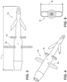
- FIG. 1 generally illustrates an embodiment of an adapter 10 according to the invention, but without the foam component 40 that is discussed further below.
- An adapter includes a longitudinal body 12 with a first end 14 that is configured for connection with a dip tube and a second end 16 that is configured for connection with a foam component.
- the adapter may be comprised of a plastic material.
- a cross piece may be disposed between the first end and the second end.
- such an adapter 10 may be disposed (e.g., pushed or inserted) into or onto a dip tube, and the adapter 10 may be held or generally retained in place/position by a feature associated with the adapter.
- a conical formation on the adapter may also form a seal between it and a dip tube, such as around the edges of the conical formation.
- the adapter 10 may have an overall width W (see, e.g., FIG. 5 ) that is less than about one-half of an overall length L of the adapter (see, e.g., FIG. 3 ).
- an embodiment of an adapter 10 may have an overall length L, which may be about 27 mm, and an overall width W, which may be about 12 mm.
- a portion of adapter 10 extends into a foam component 40, or foam 40.
- an adapter may be used to, at least in part, take the place of a dip tube. That is, with some embodiments, a portion of a dip tube may extend into an adapter, which in turn may extend at least partially into a foam component.
- the adapter may include an aperture or hole - which may essentially take the place of, or perform a similar function, as a hole associated with a dip tube. As such, fluid in the container may be in (or be absorbed into) the foam component covering the aperture or hole in the adapter, and such fluid may be drawn into the aperture or hole.
- the fluid may, for example, comprise liquor. However, the fluid may also comprise some of the gas in the container if the gas is soluble. For example, carbon dioxide (CO2) can exist both in a fluid and above it.
- CO2 carbon dioxide
- an adapter can provide a number of advantages.
- an internal aperture or hole in the adapter may increase in an area where an inlet hole for air is disposed or situated.
- a portion of the adapter 10 may include an expanded chamber 30.
- Such a configuration can create or provide a larger chamber, which can create or be associated with a drop in pressure of an incoming fluid. Such a pressure drop can permit gas to be pulled or sucked into a small hole and it can mix with fluid from the container.
- the hole 20 (which may comprise a tangential airhole, such as generally shown in FIG. 2 ) may become or be used as a venturi hole.
- the ratio of air or gas to fluid can be varied.
- the higher the ratio between the inlet and venturi hole the lower the ratio of gas to incoming fluid, and vice versa.
- the hole 20 may be sized to have a diameter from about 0.1mm to about 0.6 mm.
- the hole 20 may have, for example and without limitation, as diameter of about 0.25 mm or 0.40 mm, and may depend on flow.
- the larger the nozzle the smaller the associated hole.
- the inclusion of a venturi arrangement may also permit or cause the gas-to-fluid ration to be reduced as the container/can pressure reduces.
- Such an effect can be useful, for example, if a user has somehow wasted gas. That is, if a user has somehow wasted gas, then the device cannot afford to use as high a ratio as it would if no gas had been wasted (as the final gas pressure may be too low).
- a foam 40 may hold a significant volume of a fluid.
- the fluid is alcohol or liquor
- the present concept is not restricted to such a specific placement.
- a cross piece 50 may be included with the adapter.
- the cross piece 50 may be configured so that a portion of the cross piece 50 will contact a top portion of the foam 40 and help to position the venturi hole 20 relative to the cross piece 50 (such as in the tooling).
- the foam 40 can simply be disposed or put over the adapter 10, so the foam 40 may contact or touch the cross piece 50 (see, e.g., FIG. 2 ).
- an adapter may include a second/smaller cross piece 70 (see, e.g., FIGS. 3 and 4 ).
- FIG. 5 generally illustrates a top view of an embodiment of an adapter such as generally illustrated in FIGS. 3 and 4 .
- a small slit may be provided or made in the foam 40, and the slit may extend just downstream of the barbs 60 when in position and the adapter 10 is pushed into the slit and beyond it until the foam 40 meets or contacts the cross piece 50.
- the one or more barbs 60 are preferably pressed inwardly (radial direction) prior to the insertion, so the barbs 60 can extend outwardly once in position and can help hold the foam 40 in position with respect to the adapter 10.
- the foam can then, if desired, be rotated (e.g., through 90 degrees) so that a barb 70 pushes or forces its way inside the foam 40 and can then even more firmly secure the foam 40 to the adapter 10.
- the foam may be relatively soft, so portions of an adapter may be able to move inside the foam either by cutting, displacing, or deforming the foam. Further, when a slit is included in the foam, the slit may tend to be resilient and close around portions of an adapter, which can serve as a seal with respect to portions of the adapter. Also, portions of the adapter that are intended to be disposed within a foam may have shaped ends or portions that can cut or otherwise move through the foam when inserted or moved therein.
- More than one gas inlet hole can be included with an adapter and under the foam. However, with some embodiments it has been found that one is sufficient and, for some applications, may even be preferable. Varying the position of the holes or holes, and the start of the large chamber relative to the upstream end of the adapter, can vary the amount of fluid left in the container/can when gas enters through the venturi hole.
Landscapes
- Chemical & Material Sciences (AREA)
- Dispersion Chemistry (AREA)
- Engineering & Computer Science (AREA)
- Mechanical Engineering (AREA)
- Containers And Packaging Bodies Having A Special Means To Remove Contents (AREA)
- Quick-Acting Or Multi-Walled Pipe Joints (AREA)
- Nozzles (AREA)
Claims (15)
- Ein Adapter für einen Spender, wobei der Adapter (10) Folgendes umfasst:einen Längskörper (12) mit:einem ersten Ende (14), das zur Verbindung mit einem Tauchrohr konfiguriert ist; undeinem zweiten Ende (16), das zur Verbindung mit einer Schaumkomponente konfiguriert ist; undeine Schaumkomponente (40);dadurch gekennzeichnet, dassdie Schaumkomponente (40) um das zweite Ende (16) des Längskörpers (12) herum angeordnet ist;wobei das zweite Ende (16) des Längskörpers (12) im Wesentlichen innerhalb der Schaumkomponente (40) liegt.
- Der Adapter nach Anspruch 1, wobei der Adapter (10) aus Kunststoff besteht.
- Adapter nach Anspruch 1, wobei der Adapter (10) an oder um ein Ende des Adapters (10) eine konische Formation aufweist, die eine Dichtung zwischen dem Adapter (10) und einem Tauchrohr bildet.
- Adapter nach Anspruch 1, wobei der Adapter (10) eine Gesamtlänge (L) von etwa 27 mm hat.
- Adapter nach Anspruch 1, wobei der Adapter (10) eine Gesamtbreite (W) aufweist, die weniger als etwa die Hälfte der Gesamtlänge (L) des Adapters (10) beträgt.
- Adapter nach Anspruch 1, wobei der Adapter (10) ein Loch aufweist, das von der Schaumstoffkomponente (40) bedeckt und so konfiguriert ist, dass es ein Fluid ansaugt, wobei das Fluid nicht mehr durch das Loch in dem Adapter (10), das von der Schaumstoffkomponente (40) bedeckt ist, angesaugt werden kann, sondern Gas durch das Loch in dem Adapter (10) angesaugt werden kann; wobei die Schaumstoffkomponente (40) Schaumstoff umfasst.
- Adapter nach Anspruch 1, wobei ein Teil des Adapters (10) eine expandierte Kammer (30) aufweist, die so konfiguriert ist, dass sie einen mit einem Fluid verbundenen Druckabfall erleichtert, wobei die expandierte Kammer (30) es ermöglicht, dass Gas in ein Loch (20) des Adapters (10) gezogen oder gesaugt wird, um sich mit einem Fluid in einem zugehörigen Behälter zu vermischen, wobei die expandierte Kammer (30) zwischen dem zweiten Ende (16) und einem Querstück (50) des Adapters (10) angeordnet ist.
- Adapter nach Anspruch 7, wobei der Adapter (10) ein Luftloch aufweist, wobei das Luftloch in der erweiterten Kammer (30) vorgesehen ist.
- Adapter nach Anspruch 1 mit einem Einlassloch und einem Luftloch, wobei das entsprechende Verhältnis von einströmendem Gas zu einströmendem Fluid umso geringer ist, je größer das Verhältnis des Durchmessers des Einlasslochs zum Durchmesser des Luftlochs ist, und umgekehrt.
- Adapter nach Anspruch 1, mit dem Querstück (50), das entlang des Längskörpers (12) zwischen dem ersten Ende (14) und dem zweiten Ende (16) angeordnet ist.
- Adapter nach Anspruch 10, dadurch gekennzeichnet, dass die Schaumstoffkomponente (40) um mindestens einen Teil des zweiten Endes (16) angeordnet ist, wobei das Querstück (50) die Schaumstoffkomponente (40) berührt oder kontaktiert.
- Adapter nach Anspruch 10, dadurch gekennzeichnet, dass die Schaumstoffkomponente (40) um mindestens einen Teil des zweiten Endes (16) herum angeordnet ist, wobei der Adapter (10) einen oder mehrere Widerhaken (60) aufweist, die radial nach außen in die Schaumstoffkomponente (40) hineinragen.
- Adapter nach Anspruch 12, wobei sich der eine oder die mehreren Widerhaken (60) in einem spitzen Winkel (Ø) zum Längskörper (12) radial nach außen erstrecken.
- Adapter nach Anspruch 12, wobei das Querstück (50) zwei Widerhaken (60) aufweist, die in einem Winkel von etwa 180 Grad zueinander um den Adapter (10) herum angeordnet sind.
- Adapter nach Anspruch 12, wobei die Schaumstoffkomponente (40) einen Schlitz aufweist.
Applications Claiming Priority (2)
| Application Number | Priority Date | Filing Date | Title |
|---|---|---|---|
| US201862756159P | 2018-11-06 | 2018-11-06 | |
| PCT/IB2019/059554 WO2020095235A1 (en) | 2018-11-06 | 2019-11-06 | Adapter and dispenser with adapter |
Publications (3)
| Publication Number | Publication Date |
|---|---|
| EP3877293A1 EP3877293A1 (de) | 2021-09-15 |
| EP3877293C0 EP3877293C0 (de) | 2025-07-02 |
| EP3877293B1 true EP3877293B1 (de) | 2025-07-02 |
Family
ID=68582064
Family Applications (1)
| Application Number | Title | Priority Date | Filing Date |
|---|---|---|---|
| EP19804861.3A Active EP3877293B1 (de) | 2018-11-06 | 2019-11-06 | Adapter und spender mit einem adapter |
Country Status (7)
| Country | Link |
|---|---|
| US (1) | US11401104B2 (de) |
| EP (1) | EP3877293B1 (de) |
| AU (1) | AU2019375093B2 (de) |
| CA (2) | CA3118731C (de) |
| ES (1) | ES3041800T3 (de) |
| MX (1) | MX2021005260A (de) |
| WO (1) | WO2020095235A1 (de) |
Families Citing this family (1)
| Publication number | Priority date | Publication date | Assignee | Title |
|---|---|---|---|---|
| US11253111B2 (en) | 2019-08-22 | 2022-02-22 | Gpcp Ip Holdings Llc | Skin care product dispensers and associated self-foaming compositions |
Citations (2)
| Publication number | Priority date | Publication date | Assignee | Title |
|---|---|---|---|---|
| JP2007320639A (ja) * | 2006-06-02 | 2007-12-13 | Daizo:Kk | 人体用エアゾール製品 |
| CN106185060A (zh) * | 2016-08-31 | 2016-12-07 | 广东三和化工科技有限公司 | 一种可倒喷、防堵塞气雾剂装置 |
Family Cites Families (12)
| Publication number | Priority date | Publication date | Assignee | Title |
|---|---|---|---|---|
| US3044650A (en) * | 1959-08-11 | 1962-07-17 | Oltion John | Nursing nipple straw |
| GB1184065A (en) * | 1966-06-03 | 1970-03-11 | Sterwin Ag | Improvements in or relating to devices for Dispensing Liquids in Atomised Form |
| FR1565071A (de) * | 1968-04-25 | 1969-04-25 | ||
| AT307305B (de) * | 1971-05-28 | 1973-05-25 | Tolamin Desinfektionsmittel Ge | Sprühvorrichtung für Aerosol-Behälter |
| GB1576810A (en) * | 1976-02-17 | 1980-10-15 | Metal Box Co Ltd | Valve assemblies for aerosol containers |
| US5195664A (en) * | 1992-04-03 | 1993-03-23 | Steven Rhea | All directional fluid pick-up |
| GB2356674A (en) * | 1999-11-27 | 2001-05-30 | Carl John Simmons | Absorbent body attached to a dip tube of a pump spray dispenser or aerosol container |
| US7240810B2 (en) | 2002-11-08 | 2007-07-10 | S.C. Johnson & Son, Inc. | Flexible supply tube with weighting mechanism for use in spray bottles |
| BRPI0406611B1 (pt) * | 2003-01-30 | 2017-12-19 | Unilever N.V. | A dispenser for providing a mixture of two or more fluids and methods for providing a foam or mist, and for treating or cleaning a surface with a foam or mist |
| US8961050B2 (en) * | 2009-10-15 | 2015-02-24 | Rmi Polymers, Inc. | Filtered fluid pump dispenser with direct application mode |
| US20150001317A1 (en) * | 2013-06-27 | 2015-01-01 | Chuang Wei | Water absorbing apparatus for water spray container |
| GB201312362D0 (en) | 2013-07-10 | 2013-08-21 | Leafgreen Ltd | A divider part for containers |
-
2019
- 2019-11-06 EP EP19804861.3A patent/EP3877293B1/de active Active
- 2019-11-06 CA CA3118731A patent/CA3118731C/en active Active
- 2019-11-06 ES ES19804861T patent/ES3041800T3/es active Active
- 2019-11-06 AU AU2019375093A patent/AU2019375093B2/en active Active
- 2019-11-06 US US16/675,567 patent/US11401104B2/en active Active
- 2019-11-06 MX MX2021005260A patent/MX2021005260A/es unknown
- 2019-11-06 CA CA3146641A patent/CA3146641C/en active Active
- 2019-11-06 WO PCT/IB2019/059554 patent/WO2020095235A1/en not_active Ceased
Patent Citations (2)
| Publication number | Priority date | Publication date | Assignee | Title |
|---|---|---|---|---|
| JP2007320639A (ja) * | 2006-06-02 | 2007-12-13 | Daizo:Kk | 人体用エアゾール製品 |
| CN106185060A (zh) * | 2016-08-31 | 2016-12-07 | 广东三和化工科技有限公司 | 一种可倒喷、防堵塞气雾剂装置 |
Also Published As
| Publication number | Publication date |
|---|---|
| CA3146641A1 (en) | 2020-05-14 |
| AU2019375093A1 (en) | 2021-06-03 |
| ES3041800T3 (en) | 2025-11-14 |
| CA3118731C (en) | 2022-03-29 |
| US20200140184A1 (en) | 2020-05-07 |
| US11401104B2 (en) | 2022-08-02 |
| CA3146641C (en) | 2024-05-07 |
| CA3118731A1 (en) | 2020-05-14 |
| MX2021005260A (es) | 2023-01-05 |
| EP3877293C0 (de) | 2025-07-02 |
| AU2019375093B2 (en) | 2021-12-23 |
| EP3877293A1 (de) | 2021-09-15 |
| WO2020095235A1 (en) | 2020-05-14 |
Similar Documents
| Publication | Publication Date | Title |
|---|---|---|
| US8875951B2 (en) | Aerosol cap and system for dispensing a fluid from a canister | |
| EP3019281B1 (de) | Spender mit einem vorratsbehältnis mit einem trenner oder einem porösen material | |
| RU2008134476A (ru) | Сжимаемый вспениватель | |
| US7690536B2 (en) | Foam dispenser | |
| EP3877293B1 (de) | Adapter und spender mit einem adapter | |
| CN111108049B (zh) | 喷雾产品 | |
| CN101505877A (zh) | 弹性下悬管及其使用方法 | |
| KR101429615B1 (ko) | 일액형 폴리우레탄 폼의 디스펜싱 어댑터 | |
| CN1984816B (zh) | 泡沫分配器 | |
| US20020074364A1 (en) | Liquid sucking and dispensing device | |
| JP6312398B2 (ja) | 吐出容器 | |
| KR101454748B1 (ko) | 액상 내용물의 정량 인출이 가능한 용기 | |
| JP3240810B2 (ja) | 泡状注出容器 | |
| CN113474087A (zh) | 用于分配流体或混合物的装置 | |
| JP2706761B2 (ja) | フォーム用ディスペンサー | |
| JP2007326579A (ja) | 噴出器の内容物混合装置、および噴出器 | |
| JP3233080U (ja) | スプレーボトル | |
| CN112218804A (zh) | 分配器适配器 | |
| JP6132433B2 (ja) | 倒立型エアゾール用バルブ、該バルブを備える倒立型エアゾール用容器、並びに該エアゾール用容器に内容物が充填された倒立型エアゾール製品 | |
| CN101808912A (zh) | 一种容器 | |
| KR200383512Y1 (ko) | 디스펜서 | |
| JPS6238948Y2 (de) | ||
| JP2008184199A (ja) | 噴出器 |
Legal Events
| Date | Code | Title | Description |
|---|---|---|---|
| STAA | Information on the status of an ep patent application or granted ep patent |
Free format text: STATUS: UNKNOWN |
|
| STAA | Information on the status of an ep patent application or granted ep patent |
Free format text: STATUS: THE INTERNATIONAL PUBLICATION HAS BEEN MADE |
|
| PUAI | Public reference made under article 153(3) epc to a published international application that has entered the european phase |
Free format text: ORIGINAL CODE: 0009012 |
|
| STAA | Information on the status of an ep patent application or granted ep patent |
Free format text: STATUS: REQUEST FOR EXAMINATION WAS MADE |
|
| 17P | Request for examination filed |
Effective date: 20210528 |
|
| AK | Designated contracting states |
Kind code of ref document: A1 Designated state(s): AL AT BE BG CH CY CZ DE DK EE ES FI FR GB GR HR HU IE IS IT LI LT LU LV MC MK MT NL NO PL PT RO RS SE SI SK SM TR |
|
| DAV | Request for validation of the european patent (deleted) | ||
| DAX | Request for extension of the european patent (deleted) | ||
| STAA | Information on the status of an ep patent application or granted ep patent |
Free format text: STATUS: EXAMINATION IS IN PROGRESS |
|
| 17Q | First examination report despatched |
Effective date: 20230302 |
|
| GRAP | Despatch of communication of intention to grant a patent |
Free format text: ORIGINAL CODE: EPIDOSNIGR1 |
|
| STAA | Information on the status of an ep patent application or granted ep patent |
Free format text: STATUS: GRANT OF PATENT IS INTENDED |
|
| INTG | Intention to grant announced |
Effective date: 20250128 |
|
| GRAS | Grant fee paid |
Free format text: ORIGINAL CODE: EPIDOSNIGR3 |
|
| GRAA | (expected) grant |
Free format text: ORIGINAL CODE: 0009210 |
|
| STAA | Information on the status of an ep patent application or granted ep patent |
Free format text: STATUS: THE PATENT HAS BEEN GRANTED |
|
| AK | Designated contracting states |
Kind code of ref document: B1 Designated state(s): AL AT BE BG CH CY CZ DE DK EE ES FI FR GB GR HR HU IE IS IT LI LT LU LV MC MK MT NL NO PL PT RO RS SE SI SK SM TR |
|
| REG | Reference to a national code |
Ref country code: GB Ref legal event code: FG4D |
|
| REG | Reference to a national code |
Ref country code: CH Ref legal event code: EP |
|
| REG | Reference to a national code |
Ref country code: DE Ref legal event code: R096 Ref document number: 602019072008 Country of ref document: DE |
|
| REG | Reference to a national code |
Ref country code: IE Ref legal event code: FG4D |
|
| U01 | Request for unitary effect filed |
Effective date: 20250801 |
|
| U07 | Unitary effect registered |
Designated state(s): AT BE BG DE DK EE FI FR IT LT LU LV MT NL PT RO SE SI Effective date: 20250814 |
|
| REG | Reference to a national code |
Ref country code: ES Ref legal event code: FG2A Ref document number: 3041800 Country of ref document: ES Kind code of ref document: T3 Effective date: 20251114 |
|
| REG | Reference to a national code |
Ref country code: CH Ref legal event code: W10 Free format text: ST27 STATUS EVENT CODE: U-0-0-W10-W00 (AS PROVIDED BY THE NATIONAL OFFICE) Effective date: 20251203 |
|
| RAP4 | Party data changed (patent owner data changed or rights of a patent transferred) |
Owner name: PLASTIKPAK BAWT S.A.R.L. |
|
| U1H | Name or address of the proprietor changed after the registration of the unitary effect |
Owner name: PLASTIKPAK BAWT S.A.R.L.; LU |
|
| U20 | Renewal fee for the european patent with unitary effect paid |
Year of fee payment: 7 Effective date: 20251125 |
|
| PG25 | Lapsed in a contracting state [announced via postgrant information from national office to epo] |
Ref country code: IS Free format text: LAPSE BECAUSE OF FAILURE TO SUBMIT A TRANSLATION OF THE DESCRIPTION OR TO PAY THE FEE WITHIN THE PRESCRIBED TIME-LIMIT Effective date: 20251102 |
|
| PG25 | Lapsed in a contracting state [announced via postgrant information from national office to epo] |
Ref country code: NO Free format text: LAPSE BECAUSE OF FAILURE TO SUBMIT A TRANSLATION OF THE DESCRIPTION OR TO PAY THE FEE WITHIN THE PRESCRIBED TIME-LIMIT Effective date: 20251002 |
|
| PG25 | Lapsed in a contracting state [announced via postgrant information from national office to epo] |
Ref country code: HR Free format text: LAPSE BECAUSE OF FAILURE TO SUBMIT A TRANSLATION OF THE DESCRIPTION OR TO PAY THE FEE WITHIN THE PRESCRIBED TIME-LIMIT Effective date: 20250702 |