EP3877239B1 - Assembly with a vehicle side structure and method of making such an assembly - Google Patents
Assembly with a vehicle side structure and method of making such an assembly Download PDFInfo
- Publication number
- EP3877239B1 EP3877239B1 EP19795578.4A EP19795578A EP3877239B1 EP 3877239 B1 EP3877239 B1 EP 3877239B1 EP 19795578 A EP19795578 A EP 19795578A EP 3877239 B1 EP3877239 B1 EP 3877239B1
- Authority
- EP
- European Patent Office
- Prior art keywords
- bracket
- lining
- arrangement
- roof
- pillar
- Prior art date
- Legal status (The legal status is an assumption and is not a legal conclusion. Google has not performed a legal analysis and makes no representation as to the accuracy of the status listed.)
- Active
Links
- 238000004519 manufacturing process Methods 0.000 title description 2
- 238000000034 method Methods 0.000 claims description 32
- 238000003466 welding Methods 0.000 claims description 27
- 239000011521 glass Substances 0.000 claims description 22
- 230000002787 reinforcement Effects 0.000 description 16
- 239000002184 metal Substances 0.000 description 11
- 238000004026 adhesive bonding Methods 0.000 description 7
- 239000000463 material Substances 0.000 description 5
- 230000000712 assembly Effects 0.000 description 3
- 238000000429 assembly Methods 0.000 description 3
- 230000003014 reinforcing effect Effects 0.000 description 3
- 239000003292 glue Substances 0.000 description 2
- 230000014759 maintenance of location Effects 0.000 description 2
- 230000004913 activation Effects 0.000 description 1
- 239000011324 bead Substances 0.000 description 1
- 238000009434 installation Methods 0.000 description 1
- 238000003032 molecular docking Methods 0.000 description 1
- 238000003860 storage Methods 0.000 description 1
- 210000001364 upper extremity Anatomy 0.000 description 1
Images


Classifications
-
- B—PERFORMING OPERATIONS; TRANSPORTING
- B62—LAND VEHICLES FOR TRAVELLING OTHERWISE THAN ON RAILS
- B62D—MOTOR VEHICLES; TRAILERS
- B62D25/00—Superstructure or monocoque structure sub-units; Parts or details thereof not otherwise provided for
-
- B—PERFORMING OPERATIONS; TRANSPORTING
- B62—LAND VEHICLES FOR TRAVELLING OTHERWISE THAN ON RAILS
- B62D—MOTOR VEHICLES; TRAILERS
- B62D25/00—Superstructure or monocoque structure sub-units; Parts or details thereof not otherwise provided for
- B62D25/02—Side panels
-
- B—PERFORMING OPERATIONS; TRANSPORTING
- B62—LAND VEHICLES FOR TRAVELLING OTHERWISE THAN ON RAILS
- B62D—MOTOR VEHICLES; TRAILERS
- B62D25/00—Superstructure or monocoque structure sub-units; Parts or details thereof not otherwise provided for
- B62D25/04—Door pillars ; windshield pillars
-
- B—PERFORMING OPERATIONS; TRANSPORTING
- B62—LAND VEHICLES FOR TRAVELLING OTHERWISE THAN ON RAILS
- B62D—MOTOR VEHICLES; TRAILERS
- B62D25/00—Superstructure or monocoque structure sub-units; Parts or details thereof not otherwise provided for
- B62D25/06—Fixed roofs
-
- B—PERFORMING OPERATIONS; TRANSPORTING
- B62—LAND VEHICLES FOR TRAVELLING OTHERWISE THAN ON RAILS
- B62D—MOTOR VEHICLES; TRAILERS
- B62D27/00—Connections between superstructure or understructure sub-units
- B62D27/02—Connections between superstructure or understructure sub-units rigid
-
- B—PERFORMING OPERATIONS; TRANSPORTING
- B62—LAND VEHICLES FOR TRAVELLING OTHERWISE THAN ON RAILS
- B62D—MOTOR VEHICLES; TRAILERS
- B62D27/00—Connections between superstructure or understructure sub-units
- B62D27/02—Connections between superstructure or understructure sub-units rigid
- B62D27/023—Assembly of structural joints
-
- B—PERFORMING OPERATIONS; TRANSPORTING
- B60—VEHICLES IN GENERAL
- B60Y—INDEXING SCHEME RELATING TO ASPECTS CROSS-CUTTING VEHICLE TECHNOLOGY
- B60Y2304/00—Optimising design; Manufacturing; Testing
- B60Y2304/05—Reducing production costs, e.g. by redesign
-
- B—PERFORMING OPERATIONS; TRANSPORTING
- B60—VEHICLES IN GENERAL
- B60Y—INDEXING SCHEME RELATING TO ASPECTS CROSS-CUTTING VEHICLE TECHNOLOGY
- B60Y2304/00—Optimising design; Manufacturing; Testing
- B60Y2304/07—Facilitating assembling or mounting
Definitions
- the invention relates to a bay pillar lining of a vehicle body.
- the invention also relates to an arrangement comprising such a bay pillar lining.
- the invention also relates to a vehicle comprising such a bay pillar lining and/or such an arrangement.
- the invention also relates to a method for obtaining a lateral structure of a vehicle body.
- the invention finally relates to a method for obtaining such an arrangement.
- a vehicle in particular a motor vehicle, generally includes a body.
- a body generally includes a lateral structure on the left side and a lateral structure on the right side.
- Such lateral structures generally each include a bay pillar lining, that is to say a wall extending on the side of a windshield and which can extend beyond the windshield towards the rear according to the longitudinal direction.
- bay pillar linings generally include a reinforcement or stretcher.
- a side structure generally includes a middle pillar arranged substantially vertically behind a front door opening.
- Crosspieces then generally extend transversely at the level of a roof or pavilion between the lateral structure on the left side and the lateral structure on the right side. Such crosspieces are generally attached to the stretchers on the bay post or center pillar linings.
- the aim of the invention is to provide an arrangement of a body which overcomes the above drawbacks and improves the arrangements of the state of the art.
- the invention proposes a simple, inexpensive arrangement that is compatible with different versions of a vehicle.
- the invention relates to an arrangement comprising a lateral structure of a vehicle, in particular a motor vehicle, a front roof cross member and a central roof cross member, the front roof cross member and the central roof cross member extending transversely or substantially transversely, the lateral structure comprising a middle pillar lining and a bay pillar lining of a vehicle body, the arrangement comprising a first bracket fixed to the bay pillar lining and to the front roof crosspiece , the bay pillar lining extending beyond a middle leg towards the rear of such a body in the longitudinal or substantially longitudinal direction.
- the arrangement may include a second bracket fixed to the central roof crosspiece and to the bay pillar lining and to the middle pillar lining.
- the side structure comprises a rear stretcher liner, in particular fixed at a rear end of the bay pillar liner.
- the arrangement comprises a rear stretcher lining, in particular fixed at a rear end of the bay pillar lining, and a fourth bracket fixed on the rear stretcher lining and on the central roof crosspiece.
- the arrangement may include a third bracket fixed to the middle leg lining and to the bay post lining, the third bracket which may be intended to participate in the fixing of a glass roof and/or a sliding roof.
- the arrangement may include a support intended to participate in the fixing of a glass roof and/or a sunroof, in particular a support integrating a gluing track.
- the arrangement may include a rear handle trigger guard, in particular fixed to the rear stretcher lining by at least one rivet and/or welding.
- the arrangement may include a front handle trigger guard, in particular fixed to the bay post lining by at least one rivet and/or welding.
- the invention also relates to a vehicle, in particular a motor vehicle, comprising at least one arrangement as defined above.
- the method may include a step of providing a third bracket on the right side, respectively on the left side, and a fourth bracket on the right side, respectively on the left side, followed by a step of fixing the third bracket on the bay pillar lining, in particular by at least one rivet and/or welding, and by a step of fixing the fourth bracket on the rear stretcher lining, in particular by at least one rivet and/or welding.
- the method may include a step of providing a middle foot lining on the right side, respectively on the left side, followed by a step of fixing the second bracket on the right side, respectively on the left side, on the middle leg lining, in particular by welding several thicknesses.
- the method may include a step of providing a middle foot lining on the right side, respectively on the left side, followed by a step of fixing the third bracket on the right side, respectively on the left side, on the middle leg lining, in particular by welding several thicknesses.
- the method may comprise a step of providing a ring of reinforcements on the right side, respectively on the left side, in particular a ring of reinforcements comprising a front foot reinforcement on the right side, respectively on the left side, and/or a front stretcher reinforcement on the left side right, respectively left side, and/or a middle leg reinforcement on the right side, respectively on the left side, and/or a flap reinforcement on the right side, respectively on the left side, followed by a step of fixing this ring of reinforcements to the structure lateral right side, respectively left side, in particular by welding.
- the method may comprise a step of providing a body side skin on the right side, respectively on the left side, followed by a step of fixing this body side skin to the lateral structure on the right side, respectively on the left side, in particular by welding.
- the method may include a step of providing a support on the right side, respectively on the left side, intended to participate in the fixing of a glass and/or opening roof, in particular a support integrating a gluing track, followed by a step of fixing the support on the lateral structure on the right side, respectively on the left side, in particular by at least one rivet and/or welding.
- the method may include a step of supplying a front roof cross member and a central roof cross member, followed by a step of fixing the front roof cross member on the lateral structure, in particular placed on the first bracket then welded , and a step of fixing the central roof crosspiece on the side structure, in particular placed on the second bracket or on the fourth bracket then welded.
- the method may include a step of providing a front roof cross member closing element followed by a step of fixing this closing element to the front roof cross member.
- FIG. 1 is a schematic side view of a motor vehicle according to one embodiment of the invention.
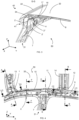
- FIG. 2 is a partial perspective view of a body of a vehicle, from the interior, according to one embodiment of the invention.
- FIG. 3 is a partial sectional view along a vertical and transverse plane of an arrangement according to one embodiment of the invention.
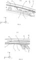
- FIG. 4 is a partial perspective view of a body of a vehicle, from the inside, according to a variant of the embodiment of the invention.
- THE figures 5, 6 , 7 and 8 are partial sectional views along vertical and transverse planes of the arrangement according to the variant of the embodiment.
- the direction in which the vehicle moves in a straight line is defined as the longitudinal direction X.
- the direction perpendicular to the longitudinal direction perpendicular to the other two, is called vertical direction Z.
- FIG. 1 illustrates a vehicle according to one embodiment, in particular a motor vehicle 20.
- the motor vehicle 20 comprises a body 30.
- the body 30 comprises a lateral structure on the left side and a lateral structure on the right side.
- the lateral structure 40 on the right side, respectively on the left side comprises a bay pillar lining 2 on the right side, respectively on the left side.
- Each bay post liner is generally covered with a corresponding bay post 22.
- each bay pillar lining extends on each side of a windshield 21 as well as towards the rear of the body 30.
- the lateral structure 40 on the right side, respectively on the left side also includes a lining of middle foot 7 right side, respectively left side.
- the lateral structure 40 on the right side, respectively on the left side further comprises a rear stretcher lining 5 on the right side, respectively on the left side.
- the bay pillar lining 2 extends beyond a middle leg 31 in the longitudinal or substantially longitudinal direction towards the rear of the body 30.
- the motor vehicle 20 further comprises an arrangement 50.
- the arrangement 50 comprises the lateral structure 40, a front roof cross member 9 and a central roof cross member 8.
- the front roof cross member 9 extends transversely or substantially transversely.
- the central roof crosspiece 8 also extends transversely or substantially transversely.
- the arrangement 50 comprises a first bracket 1.
- the first bracket 1 is fixed on the bay pillar lining 2 and on the front roof crosspiece 9.
- This arrangement preferably corresponds to the case of a motor vehicle 20 equipped with a roof or so-called “normal” roof, that is to say sheet metal 32.
- a roof is preferably devoid of glazed or glass part and preferably comprises sheet metal.
- the arrangement 50 also includes a second bracket 4.
- the second bracket 4 is fixed on the central roof crosspiece 8 and on the bay pillar lining 2 and on the middle leg lining 7.
- the side structure 40 also includes a lining rear stretcher 5.
- the rear stretcher lining 5 is fixed at a rear end 2R of the bay pillar lining 2.
- the arrangement 50 comprises a rear handle trigger guard 6.
- the bridge 6 allows the attachment of a handle allowing a rear passenger to stand, for example in the event of a turn, near the roof, for example above a rear window or a rear door frame.
- the rear handle trigger guard 6 is then fixed to the rear stretcher lining 5, for example by means of at least one rivet and/or welding.
- the bridge 6 is pre-positioned using two rivets before being welded.
- the arrangement 50 comprises a bridge 3 front handle on the right.
- the bridge 3 allows the attachment of a handle allowing a front passenger to hold, for example in the event of a turn, close to the roof, for example above the frame of the front passenger door.
- the front handle trigger guard 3 is located on the bay post lining 2 on the right side.
- the front handle trigger guard 3 is then fixed by means of at least one rivet and/or welding.
- the bridge 3 is pre-positioned using two rivets before being welded.
- the arrangement 50 comprises the lateral structure 40, a front roof crosspiece 13 and a central roof crosspiece 14.
- This variant preferably corresponds to a motor vehicle 20 equipped with a glass or glazed roof and/or or opening 33.
- the front roof crossbar 13, just like the roof crossbar central 14 extend transversely or substantially transversely.
- the lateral structure 40 comprises the middle leg lining 7, the rear stretcher lining 5 and the bay pillar lining 2.
- the arrangement 50 also includes the first bracket 1.
- the first bracket 1 is fixed on the bay pillar lining 2 and on the front roof crossbar 13.
- the arrangement 50 also includes a fourth bracket 12.
- the fourth bracket 12 is fixed on the rear stretcher lining 5 and on the central roof crossbar 14
- the arrangement 50 also comprises a third bracket 11.
- the third bracket 11 is fixed on the middle leg lining 7 and on the bay post lining 2.
- the third bracket 11 is thus intended to participate in the fixing. of the glass and/or opening roof 33.
- the arrangement 50 further comprises a support 10.
- the support 10 is intended to participate in the fixing of the glass and/or opening roof 33.
- the support 10 or lateral element can be put in place without consequence on the version with sheet metal roof 32.
- the bridge 3 can be arranged with a sheet metal roof 32 as well as a glass and/or opening roof 33.
- the support 10 is arranged on a rim 22' of the bay pillar 22.
- the support 10 or lateral connecting element of the fixed or opening glass roof 33 integrates the gluing track function.
- a gluing track that is to say a surface intended to receive glue, for example a bead of glue S, helping to hold the glazed part of the roof for example on the support 10, is provided.
- the gluing track can be used for fixing of a fixed glass roof glazing or for fixing a fixed side and front part of a sliding roof.
- the gluing track extends at the level of the third bracket 11 on the support 10, up to the central roof crosspiece 14.
- the gluing track can be used to attach glazing fixed glass roof or for fixing a fixed side and rear part of a sliding roof.
- a cross closure element 39 is then provided, arranged on the one hand on the first bracket 1 and on the other hand on the support 10.
- the cross closure element 39 just like the support 10, comes on the rim 22 ' of the bay amount 22.
- the first bracket 1 is geometrically designed to accept the extra thickness of the transom closure element 39.
- the first bracket 1 is also adapted .
- first bracket 1 and the second bracket 4 constitute interfaces facilitating the assembly of the front roof crosspiece 9 and the central roof crosspiece 8 with the bay pillar lining 2 in the case of the sheet metal roof 32.
- the arrangement 50 also includes a ring of reinforcements 34.
- This ring of reinforcements 34 comprises for example a front leg reinforcement and/or a front stretcher reinforcement and/or a middle leg reinforcement and/or a reinforcement of flap.
- the reinforcing ring 34 is arranged, arranged, on the top of an interior side edge 2' of the bay post lining 2.
- the reinforcing ring 34 is also fixed to the stretcher lining 5, in particular to the level of its vertical end part.
- the lower edge of the reinforcing ring 34 extends in a plane substantially identical to that of the stretcher lining 5 such that it is arranged to rest against an inner face of the stretcher lining, as is illustrated in the figure 8 .
- the first bracket 1 constitutes an interface facilitating the assembly of the front roof crosspiece 13 with the bay pillar lining 2.
- the fourth bracket 12 constitutes a interface facilitating the assembly of the central roof crosspiece 14 with the rear stretcher lining 5.
- the third bracket 11 constitutes an interface facilitating for example the assembly of the roof 33 with the bay pillar lining 2 and participating in maintaining the item 10.
- the rear stretcher liner 5 comprises a fixing interface intended to receive either the bridge 6 for fixing a grab handle for a rear passenger in the sheet metal roof version 32, or the fourth bracket 12 for fixing the cross member of the central roof 14 in fixed glass roof or opening roof version.
- the rear stretcher lining 5 can for example receive the trigger guard 6 and the fourth bracket 12 in the fixed or opening glass roof version.
- the bay post lining 2 has a more regular shape, having little or no protrusion.
- its 2" squares or edges, illustrated on the figures 3 , 5 , 6 And 7 are not impacted by geometric accidents, that is to say that there are no or very few changes in shape.
- regularity improves performance, notably stability and behavior in the event of an impact, particularly in the event of a frontal impact.
- the regularity of the bay post lining 2 facilitates the step of obtaining the bay post lining by stamping.
- geometric conformity in other words the adherence to the geometric targets of the bay pillar lining, is easily achieved.
- the bay pillar lining 2 is of great length in the longitudinal direction. In fact, the bay pillar lining 2 extends, towards the rear of the vehicle, beyond a middle foot 23. This helps to ensure structural continuity on the bay pillar line and to reduce the presence form accidents which could lead to instabilities, such as local buckling, during frontal impact loading. In addition, the ratio between the mass of material required for production and the mass of material actually used in the final bay pillar liner is optimal.
- first bracket 1, the bay pillar lining 2, the rear stretcher lining 5 and the middle leg lining 7 are identical regardless of the type of roof, namely fixed and/or opening glass 33 or sheet metal. 32.
- the diversity of the parts is reduced, the second, third and fourth attached brackets 4, 11, 12 being treated globally so as to only manage a single reference for the lining of the bay amount 2, rear stretcher lining 5, middle pillar lining 7 and first bracket 1 for connecting the front roof crossbar 9, 13.
- the stacking and installation of docking areas are treated accordingly.
- This standardization generates significant savings, particularly in terms of storage space for the bulky bay 2 post liners, which are now standard. Indeed, for the same vehicle model, it is enough to produce right bay pillar linings and left bay pillar linings, whatever its type of roof and whatever its steering side.
- the method comprises a step of supplying the first bracket 1, the rear stretcher lining 5 and the bay pillar lining 2.
- this step of fixing the bridge 3 is carried out in two stages. In fact, firstly the bridge 3 is pre-positioned using two rivets and secondly the bridge 3 is welded to the bay post lining 2.
- the method includes a step of supplying the second bracket 4 and the bridge 6 rear handle.
- this fixing step is carried out in two stages. Indeed, initially the second bracket 4 is pre-positioned using two rivets and secondly the second bracket 4 is welded to the bay upright lining 2. Likewise, initially the bridge 6 of rear handle is pre-positioned using two rivets and secondly the trigger guard 6 is welded to the rear stretcher lining 5 and, possibly, to the bay post lining 2.
- this fixing step is carried out by welding several thicknesses, by example of welding the thickness of the middle leg lining 7 with the thickness of the second bracket 4, possibly with the thickness of the bay upright lining 2, as illustrated in the Figure 3 .
- the method comprises a step of supplying the third bracket 11 and the fourth bracket 12.
- this fixing step is carried out in two stages. Indeed, initially the third bracket 11 is pre-positioned using two rivets and secondly the third bracket 11 is welded to the bay post lining 2. Likewise, initially the fourth bracket 12 is pre-positioned using two rivets and then the fourth bracket 12 is welded to the rear stretcher lining 5. Note that these pre-positionings using rivets require preliminary holes (not shown) for the passage of the rivets.
- this fixing step is carried out by welding several thicknesses, for example welding the thickness of the middle leg lining 7 with the thickness of the third bracket 11, possibly with the thickness of the bay upright lining 2, as illustrated in the figure 7 .
- the method preferably comprises a step of providing the ring of reinforcements 34.
- a step of fixing this ring of reinforcements 34 to the lateral structure 40 is preferably carried out by welding.
- the method also includes a step of providing a body side skin 41 illustrated in particular on the figures 3 And 8 .
- the body side skin 41 on the right side, respectively on the left side comprises the bay pillar 22 on the right side, respectively on the left side.
- a step of fixing this body side skin 41 to the lateral structure 40 is carried out by welding.
- the method also includes a step of supplying the support 10 intended to participate in fixing the glass and/or opening roof 33.
- a step of fixing the support 10 on the lateral structure 40 is carried out in two stages. Indeed, initially the support 10 is pre-positioned using two rivets and secondly the support 10 is welded to the lateral structure 40. Note that these pre-positionings by means of rivets require preliminary holes (not illustrated) for the passage of the rivets.
- the support 10 is preferably fixed on the body side skin 41, more precisely on the edge 22' of the bay post 22.
- a mode of execution of a method for obtaining the arrangement 50 of the body 30 of the motor vehicle 20 is described below.
- the method of obtaining the arrangement 50 comprises a step of implementing a method of obtaining the lateral structure 40.
- the crosspieces are advantageously simply placed on their respective brackets which naturally wedge them.
- At least one retention hook 17 is provided projecting from each bracket and is intended to be inserted into at least one orifice 18 on the corresponding crosspiece.
- the retention hooks 17 associated with the orifices 18 make it possible to avoid excessive movement of the crosspieces in the vertical direction. Such a movement could cause the sleepers to move out of their respective reception areas, in particular during possible conveying prior to fixing the sleepers.
- a step of fixing the central roof cross member 8, 14 placed on the second bracket 4 or on the fourth bracket 12 is provided prior to or following this step.
- the first bracket 1 is welded to the front roof crossbar 9, 13.
- the second bracket 4 or the fourth bracket 12 is welded to the corresponding central roof crossbar 8, 14.
Description
L'invention concerne une doublure de montant de baie d'une caisse de véhicule. L'invention concerne aussi un agencement comprenant une telle doublure de montant de baie. L'invention concerne encore un véhicule comprenant une telle doublure de montant de baie et/ou un tel agencement. L'invention concerne encore un procédé d'obtention d'une structure latérale d'une caisse de véhicule. L'invention concerne enfin un procédé d'obtention d'un tel agencement.The invention relates to a bay pillar lining of a vehicle body. The invention also relates to an arrangement comprising such a bay pillar lining. The invention also relates to a vehicle comprising such a bay pillar lining and/or such an arrangement. The invention also relates to a method for obtaining a lateral structure of a vehicle body. The invention finally relates to a method for obtaining such an arrangement.
Un véhicule, en particulier un véhicule automobile, comprend généralement une caisse. Une telle caisse comprend généralement une structure latérale côté gauche et une structure latérale côté droit. De telles structures latérales comprennent généralement chacune une doublure de montant de baie, c'est-à-dire une paroi s'étendant sur le côté d'un pare-brise et pouvant aller au-delà du pare-brise vers l'arrière selon la direction longitudinale. De telles doublures de montant de baie comprennent généralement un renfort ou brancard. En outre, une structure latérale comprend généralement un pied milieu agencé sensiblement verticalement derrière une ouverture de porte avant.A vehicle, in particular a motor vehicle, generally includes a body. Such a body generally includes a lateral structure on the left side and a lateral structure on the right side. Such lateral structures generally each include a bay pillar lining, that is to say a wall extending on the side of a windshield and which can extend beyond the windshield towards the rear according to the longitudinal direction. Such bay pillar linings generally include a reinforcement or stretcher. In addition, a side structure generally includes a middle pillar arranged substantially vertically behind a front door opening.
Des traverses s'étendent alors généralement transversalement au niveau d'un toit ou pavillon entre la structure latérale côté gauche et la structure latérale côté droit. De telles traverses sont généralement fixées aux brancards sur les doublures de montant de baie ou de pied milieu.Crosspieces then generally extend transversely at the level of a roof or pavilion between the lateral structure on the left side and the lateral structure on the right side. Such crosspieces are generally attached to the stretchers on the bay post or center pillar linings.
De tels assemblages entre les traverses et les doublures de montant de baie ou de pied milieu présentent des inconvénients. D'une part ces assemblages sont complexes à réaliser et d'autre part il en résulte un mauvais engagement des matières.Such assemblies between the crosspieces and the bay post or middle leg linings have drawbacks. On the one hand these assemblies are complex to make and on the other hand it results in poor engagement of materials.
Le document
Le but de l'invention est de fournir un agencement d'une caisse remédiant aux inconvénients ci-dessus et améliorant les agencements de l'état de la technique. En particulier, l'invention propose un agencement simple, peu onéreux et compatible avec différentes versions d'un véhicule.The aim of the invention is to provide an arrangement of a body which overcomes the above drawbacks and improves the arrangements of the state of the art. In particular, the invention proposes a simple, inexpensive arrangement that is compatible with different versions of a vehicle.
Pour atteindre cet objectif, l'invention porte sur un agencement comprenant une structure latérale de véhicule, notamment de véhicule automobile, une traverse de pavillon avant et une traverse de pavillon centrale, la traverse de pavillon avant et la traverse de pavillon centrale s'étendant transversalement ou sensiblement transversalement, la structure latérale comprenant une doublure de pied milieu et une doublure de montant de baie d'une caisse de véhicule, l'agencement comprenant une première équerre fixée sur la doublure de montant de baie et sur la traverse de pavillon avant, la doublure de montant de baie s'étendant au-delà d'un pied milieu vers l'arrière d'une telle caisse selon la direction longitudinale ou sensiblement longitudinale.To achieve this objective, the invention relates to an arrangement comprising a lateral structure of a vehicle, in particular a motor vehicle, a front roof cross member and a central roof cross member, the front roof cross member and the central roof cross member extending transversely or substantially transversely, the lateral structure comprising a middle pillar lining and a bay pillar lining of a vehicle body, the arrangement comprising a first bracket fixed to the bay pillar lining and to the front roof crosspiece , the bay pillar lining extending beyond a middle leg towards the rear of such a body in the longitudinal or substantially longitudinal direction.
L'agencement peut comprendre une deuxième équerre fixée sur la traverse de pavillon centrale et sur la doublure de montant de baie et sur la doublure de pied milieu.The arrangement may include a second bracket fixed to the central roof crosspiece and to the bay pillar lining and to the middle pillar lining.
La structure latérale comprend une doublure de brancard arrière, notamment fixée au niveau d'une extrémité arrière de la doublure de montant de baie.The side structure comprises a rear stretcher liner, in particular fixed at a rear end of the bay pillar liner.
L'agencement comprend une doublure de brancard arrière, notamment fixée au niveau d'une extrémité arrière de la doublure de montant de baie, et une quatrième équerre fixée sur la doublure de brancard arrière et sur la traverse de pavillon centrale.The arrangement comprises a rear stretcher lining, in particular fixed at a rear end of the bay pillar lining, and a fourth bracket fixed on the rear stretcher lining and on the central roof crosspiece.
L'agencement peut comprendre une troisième équerre fixée sur la doublure de pied milieu et sur la doublure de montant de baie, la troisième équerre pouvant être destinée à participer à la fixation d'un toit en verre et/ou d'un toit ouvrant.The arrangement may include a third bracket fixed to the middle leg lining and to the bay post lining, the third bracket which may be intended to participate in the fixing of a glass roof and/or a sliding roof.
L'agencement peut comprendre un support destiné à participer à la fixation d'un toit en verre et/ou d'un toit ouvrant, notamment un support intégrant une piste d'encollage.The arrangement may include a support intended to participate in the fixing of a glass roof and/or a sunroof, in particular a support integrating a gluing track.
L'agencement peut comprendre un pontet de poignée arrière, notamment fixé sur la doublure de brancard arrière par au moins un rivet et/ou soudage.The arrangement may include a rear handle trigger guard, in particular fixed to the rear stretcher lining by at least one rivet and/or welding.
L'agencement peut comprendre un pontet de poignée avant, notamment fixé sur la doublure de montant de baie par au moins un rivet et/ou soudage.The arrangement may include a front handle trigger guard, in particular fixed to the bay post lining by at least one rivet and/or welding.
L'invention porte encore sur un véhicule, notamment un véhicule automobile, comprenant au moins un agencement tel que défini précédemment.The invention also relates to a vehicle, in particular a motor vehicle, comprising at least one arrangement as defined above.
L'invention porte encore sur un procédé de réalisation d'un agencement tel que défini précédemment, comprenant une troisième équerre fixée sur la doublure de pied milieu et sur la doublure de montant de baie, la troisième équerre étant destinée à participer à la fixation d'un toit en verre et/ou d'un toit ouvrant, le procédé comprenant une étape de
- fourniture d'une première équerre côté droit, respectivement côté gauche, d'une doublure de brancard arrière côté droit, respectivement côté gauche, et d'une doublure de montant de baie côté droit, respectivement côté gauche,
- suivie d'une étape de fixation de la première équerre et de la doublure de brancard arrière sur la doublure de montant de baie, notamment par soudage, et,
- en cas de présence d'une direction d'un tel véhicule côté gauche, respectivement côté droit, alors le procédé comprend une étape de fourniture d'un pontet de poignée avant côté droit, respectivement côté gauche, suivie d'une étape de fixation du pontet de poignée avant sur la doublure de montant de baie côté droit, respectivement côté gauche, notamment par au moins un rivet et/ou soudage.
- supply of a first bracket on the right side, respectively left side, of a rear stretcher lining on the right side, respectively on the left side, and of a bay pillar lining on the right side, respectively on the left side,
- followed by a step of fixing the first bracket and the rear stretcher lining to the bay pillar lining, in particular by welding, and,
- in the case of the presence of a steering of such a vehicle on the left side, respectively right side, then the method comprises a step of providing a front handle bridge on the right side, respectively left side, followed by a step of fixing the front grip trigger guard on the lining of the bay pillar on the right side, respectively on the left side, in particular by at least one rivet and/or welding.
L'invention porte encore sur un procédé selon les revendications 8 ou 9. En cas de caisse destinée à recevoir un toit tôlé, alors le procédé peut comprendre une étape de fourniture d'une deuxième équerre côté droit, respectivement côté gauche, et d'un pontet de poignée arrière côté droit, respectivement côté gauche,
- suivie d'une étape de fixation de la deuxième équerre sur la doublure de montant de baie côté droit, respectivement côté gauche, notamment par au moins un rivet et/ou soudage,
- et d'une étape de fixation du pontet de poignée arrière sur la doublure de montant de baie côté droit, respectivement côté gauche, et sur la doublure de brancard arrière côté droit, respectivement côté gauche, notamment par au moins un rivet et/ou soudage.
- followed by a step of fixing the second bracket to the bay pillar lining on the right side, respectively on the left side, in particular by at least one rivet and/or welding,
- and a step of fixing the rear handle trigger guard to the bay pillar lining on the right side, respectively on the left side, and on the rear stretcher lining on the right side, respectively on the left side, in particular by at least one rivet and/or welding .
En cas de caisse destinée à recevoir un toit vitré et/ou ouvrant, alors le procédé peut comprendre une étape de fourniture d'une troisième équerre côté droit, respectivement côté gauche, et d'une quatrième équerre côté droit, respectivement côté gauche,
suivie d'une étape de fixation de la troisième équerre sur la doublure de montant de baie, notamment par au moins un rivet et/ou soudage, et d'une étape de fixation de la quatrième équerre sur la doublure de brancard arrière, notamment par au moins un rivet et/ou soudage.In the case of a body intended to receive a glass and/or opening roof, then the method may include a step of providing a third bracket on the right side, respectively on the left side, and a fourth bracket on the right side, respectively on the left side,
followed by a step of fixing the third bracket on the bay pillar lining, in particular by at least one rivet and/or welding, and by a step of fixing the fourth bracket on the rear stretcher lining, in particular by at least one rivet and/or welding.
Le procédé peut comprendre une étape de fourniture d'une doublure de pied milieu côté droit, respectivement côté gauche,
suivie d'une étape de fixation de la deuxième équerre côté droit, respectivement côté gauche, sur la doublure de pied milieu, notamment par soudage de plusieurs épaisseurs.The method may include a step of providing a middle foot lining on the right side, respectively on the left side,
followed by a step of fixing the second bracket on the right side, respectively on the left side, on the middle leg lining, in particular by welding several thicknesses.
Le procédé peut comprendre une étape de fourniture d'une doublure de pied milieu côté droit, respectivement côté gauche, suivie d'une étape de fixation de la troisième équerre côté droit, respectivement côté gauche, sur la doublure de pied milieu, notamment par soudage de plusieurs épaisseurs.The method may include a step of providing a middle foot lining on the right side, respectively on the left side, followed by a step of fixing the third bracket on the right side, respectively on the left side, on the middle leg lining, in particular by welding several thicknesses.
Le procédé peut comprendre une étape de fourniture d'un anneau de renforts côté droit, respectivement côté gauche, notamment d'un anneau de renforts comprenant un renfort de pied avant côté droit, respectivement côté gauche, et/ou un renfort de brancard avant côté droit, respectivement côté gauche, et/ou un renfort de pied milieu côté droit, respectivement côté gauche, et/ou un renfort de bavolet côté droit, respectivement côté gauche, suivie d'une étape de fixation de cet anneau de renforts à la structure latérale côté droit, respectivement côté gauche, notamment par soudage.The method may comprise a step of providing a ring of reinforcements on the right side, respectively on the left side, in particular a ring of reinforcements comprising a front foot reinforcement on the right side, respectively on the left side, and/or a front stretcher reinforcement on the left side right, respectively left side, and/or a middle leg reinforcement on the right side, respectively on the left side, and/or a flap reinforcement on the right side, respectively on the left side, followed by a step of fixing this ring of reinforcements to the structure lateral right side, respectively left side, in particular by welding.
Le procédé peut comprendre une étape de fourniture d'une peau de côté de caisse côté droit, respectivement côté gauche, suivie d'une étape de fixation de cette peau de côté de caisse à la structure latérale côté droit, respectivement côté gauche, notamment par soudage.The method may comprise a step of providing a body side skin on the right side, respectively on the left side, followed by a step of fixing this body side skin to the lateral structure on the right side, respectively on the left side, in particular by welding.
Le procédé peut comprendre une étape de fourniture d'un support côté droit, respectivement côté gauche, destiné à participer à la fixation d'un toit en verre et/ou ouvrant, notamment un support intégrant une piste d'encollage, suivie d'une étape de fixation du support sur la structure latérale côté droit, respectivement côté gauche, notamment par au moins un rivet et/ou soudage.The method may include a step of providing a support on the right side, respectively on the left side, intended to participate in the fixing of a glass and/or opening roof, in particular a support integrating a gluing track, followed by a step of fixing the support on the lateral structure on the right side, respectively on the left side, in particular by at least one rivet and/or welding.
Le procédé peut comprendre une étape de fourniture d'une traverse de pavillon avant et d'une traverse de pavillon centrale, suivie d'une étape de fixation de la traverse de pavillon avant sur la structure latérale, notamment posée sur la première équerre puis soudée, et d'une étape de fixation de la traverse de pavillon centrale sur la structure latérale, notamment posée sur la deuxième équerre ou sur la quatrième équerre puis soudée.The method may include a step of supplying a front roof cross member and a central roof cross member, followed by a step of fixing the front roof cross member on the lateral structure, in particular placed on the first bracket then welded , and a step of fixing the central roof crosspiece on the side structure, in particular placed on the second bracket or on the fourth bracket then welded.
Le procédé peut comprendre une étape de fourniture d'un élément de fermeture de traverse de pavillon avant suivie d'une étape de fixation de cet élément de fermeture sur la traverse de pavillon avant.The method may include a step of providing a front roof cross member closing element followed by a step of fixing this closing element to the front roof cross member.
Les figures annexées représentent, à titre d'exemple, un mode de réalisation d'un véhicule.The appended figures represent, by way of example, an embodiment of a vehicle.
La
La
La
La
Les
Les
La direction selon laquelle le véhicule se déplace en ligne droite est définie comme étant la direction longitudinale X. Par convention, la direction perpendiculaire à la direction longitudinale X, située dans un plan parallèle au sol, est nommée direction transversale Y. La troisième direction, perpendiculaire aux deux autres, est nommée direction verticale Z.The direction in which the vehicle moves in a straight line is defined as the longitudinal direction X. By convention, the direction perpendicular to the longitudinal direction perpendicular to the other two, is called vertical direction Z.
La
Comme illustré en particulier sur les
Le véhicule automobile 20 comprend encore un agencement 50. L'agencement 50 comprend la structure latérale 40, une traverse de pavillon avant 9 et une traverse de pavillon centrale 8. La traverse de pavillon avant 9 s'étend transversalement ou sensiblement transversalement. La traverse de pavillon centrale 8 s'étend également transversalement ou sensiblement transversalement.The
Comme illustré sur la
En cas de véhicule automobile 20 doté d'une direction à gauche, et par conséquent d'un moyen de direction tel qu'un volant, disposé à gauche au sein de l'habitacle avant par exemple, l'agencement 50 comprend un pontet 3 de poignée avant à droite. Le pontet 3 permet la fixation d'une poignée permettant à un passager avant de se tenir, par exemple en cas de virage, à proximité du pavillon, par exemple au-dessus du cadre de la porte avant passager. Le pontet 3 de poignée avant est disposé sur la doublure de montant de baie 2 côté droit. Le pontet 3 de poignée avant est alors fixé par le biais d'au moins un rivet et/ou soudage. Avantageusement le pontet 3 est pré-positionné grâce à deux rivets avant d'être soudé.In the case of a
Comme illustré sur la
De préférence, le pontet 3 peut être agencé aussi bien avec un toit en tôle 32 qu'un toit en verre et/ou ouvrant 33.Preferably, the
Avantageusement, comme illustré sur les
Ainsi la faisabilité d'assemblage, tout comme l'engagement des matières, en particulier au niveau de la doublure de montant de baie 2 et de la doublure de brancard arrière 5 sont améliorés.Thus the assembly feasibility, as well as the engagement of materials, in particular at the level of the bay pillar lining 2 and the rear stretcher lining 5 are improved.
En effet, comme illustré sur les
A noter, que l'agencement 50 comprend encore un anneau de renforts 34. Cet anneau de renforts 34 comprend par exemple un renfort de pied avant et/ou un renfort de brancard avant et/ou un renfort de pied milieu et/ou un renfort de bavolet. Comme illustré sur les
Comme illustré sur les
A noter que la doublure de brancard arrière 5 comprend une interface de fixation destinée à recevoir soit le pontet 6 de fixation d'une poignée de maintien pour un passager arrière en version toit tôlé 32, soit la quatrième équerre 12 de fixation de la traverse de pavillon centrale 14 en version toit en verre fixe ou toit ouvrant. Alternativement, la doublure de brancard arrière 5 peut par exemple recevoir le pontet 6 et la quatrième équerre 12 en version toit en verre fixe ou ouvrant.Note that the
Grâce aux moyens de fixation que constituent les première, deuxième, troisième et quatrième équerres de liaison ou de fixation, la doublure de montant de baie 2 est dotée d'une forme plus régulière, comportant peu voire pas d'excroissance. Autrement dit, ses carres ou bords 2", illustrés sur les
De plus la doublure de montant de baie 2 est de grande longueur selon la direction longitudinale. En effet, la doublure de montant de baie 2 s'étend, vers l'arrière du véhicule, au-delà d'un pied milieu 23. Cela concourt à assurer une continuité structurelle sur la ligne de montant de baie et à réduire la présence d'accident de forme pouvant conduire à des instabilités, tels que des flambements locaux, lors du chargement en choc frontal. En outre, le rapport entre la masse de matière nécessaire à la production et la masse de matière réellement utilisée dans la doublure de montant de baie finale est optimale.In addition, the bay pillar lining 2 is of great length in the longitudinal direction. In fact, the bay pillar lining 2 extends, towards the rear of the vehicle, beyond a
Ainsi, la première équerre 1, la doublure de montant de baie 2, la doublure de brancard arrière 5 et la doublure de pied milieu 7 sont identiques quel que soit le type de pavillon, à savoir en verre fixe et/ou ouvrant 33 ou tôlé 32. Autrement dit la diversité des pièces s'en trouve réduite, les deuxième, troisième et quatrième équerres 4, 11, 12 rapportées étant traitées de manière globale de façon à ne gérer qu'une seule référence de doublure de montant de baie 2, de doublure de brancard arrière 5, de doublure de pied milieu 7 et de première équerre 1 de liaison de traverse de pavillon avant 9, 13. Evidemment, les empilages et mises en place de zones d'accostages sont traités en conséquence. Cette standardisation génère des économies conséquentes, en particulier en termes d'espace de stockage concernant les doublures de montant de baie 2 encombrantes, désormais standards. Effectivement, pour un même modèle de véhicule, il suffit de produire des doublures de montant de baie droites et des doublures de montant de baie gauches, et ce, quel que soit son type de toit et quel que soit le côté de sa direction.Thus, the
En résumé, en cas de toit tôlé 32, on a recours à la deuxième équerre 4. En cas de toit vitré 33, on n'utilise pas de deuxième équerre 4 mais une troisième équerre 11 et une quatrième équerre 12.In summary, in the case of a
Un mode d'exécution d'un procédé d'obtention de la structure latérale 40 côté droit de la caisse 30 du véhicule automobile 20 est décrit ci-après.One mode of execution of a method for obtaining the
Le procédé comprend une étape de fourniture de la première équerre 1, de la doublure de brancard arrière 5 et de la doublure de montant de baie 2. Vient ensuite une étape de fixation, de préférence par soudage, de la première équerre 1 et de la doublure de brancard arrière 5 sur la doublure de montant de baie 2.The method comprises a step of supplying the
En cas de présence de la direction du véhicule du côté gauche, vient alors une étape de fourniture du pontet 3 de poignée avant suivie d'une étape de fixation du pontet 3 de poignée avant sur la doublure de montant de baie 2 côté droit. De préférence, cette étape de fixation du pontet 3 est réalisée en deux temps. En effet, dans un premier temps le pontet 3 est pré-positionné grâce à deux rivets et dans un deuxième temps le pontet 3 est soudé sur la doublure de montant de baie 2.If the steering of the vehicle is present on the left side, then comes a step of supplying the
Evidemment, dans un procédé d'obtention de la structure latérale gauche, en cas de présence de la direction à gauche, il n'est pas prévu de fourniture ni de fixation d'un pontet de poignée avant. Par contre, dans un procédé d'obtention de la structure latérale gauche et en cas de direction à droite, le pontet de poignée avant est fixé sur la doublure de montant de baie côté gauche. Enfin, dans un procédé d'obtention de la structure latérale droite et en cas de direction à droite, il n'est pas prévu de fourniture ni de fixation d'un pontet de poignée avant.Obviously, in a method of obtaining the left lateral structure, in the event of the presence of left-hand steering, there is no provision for the provision or fixing of a front handle bridge. On the other hand, in a method of obtaining the left side structure and in the case of right-hand steering, the front handle clip is fixed on the left side bay pillar lining. Finally, in a method of obtaining the right lateral structure and in the case of right-hand steering, there is no provision for the provision or fixing of a front handle bridge.
En cas de caisse 30 destinée à recevoir le toit tôlé 32, alors le procédé comprend une étape de fourniture de la deuxième équerre 4 et du pontet 6 de poignée arrière. Vient ensuite une étape de fixation de la deuxième équerre 4 sur la doublure de montant de baie 2 et une étape de fixation du pontet 6 de poignée arrière sur la doublure de brancard arrière 5 et, éventuellement, sur la doublure de montant de baie 2. De préférence, cette étape de fixation est réalisée en deux temps. En effet, dans un premier temps la deuxième équerre 4 est pré-positionnée grâce à deux rivets et dans un deuxième temps la deuxième équerre 4 est soudée sur la doublure de montant de baie 2. De même, dans un premier temps le pontet 6 de poignée arrière est pré-positionné grâce à deux rivets et dans un deuxième temps le pontet 6 est soudé sur la doublure de brancard arrière 5 et, éventuellement, sur la doublure de montant de baie 2. A noter que ces pré-positionnements par le biais de rivets nécessitent des trous 16 préalables pour le passage des rivets, comme illustré sur la
Alternativement, en cas de caisse 30 de la variante destinée à recevoir le toit vitré et/ou ouvrant 33, alors le procédé comprend une étape de fourniture de la troisième équerre 11 et de la quatrième équerre 12. Vient ensuite une étape de fixation de la troisième équerre 11 sur la doublure de montant de baie 2 et une étape de fixation de la quatrième équerre 12 sur la doublure de brancard arrière 5. De préférence, cette étape de fixation est réalisée en deux temps. En effet, dans un premier temps la troisième équerre 11 est pré-positionnée grâce à deux rivets et dans un deuxième temps la troisième équerre 11 est soudée sur la doublure de montant de baie 2. De même, dans un premier temps la quatrième équerre 12 est pré-positionnée grâce à deux rivets et dans un deuxième temps la quatrième équerre 12 est soudée sur la doublure de brancard arrière 5. A noter que ces pré-positionnements par le biais de rivets nécessitent des trous préalables (non illustrés) pour le passage des rivets. Vient ensuite une étape de fourniture de la doublure de pied milieu 7 suivie d'une étape de fixation de la troisième équerre 11 sur la doublure de pied milieu 7. De préférence, cette étape de fixation est réalisée par soudage de plusieurs épaisseurs, par exemple de soudage de l'épaisseur de la doublure de pied milieu 7 avec l'épaisseur de la troisième équerre 11, éventuellement avec l'épaisseur de la doublure de montant de baie 2, comme illustré sur la
Quel que soit le type de toit et le côté de la direction, le procédé comprend de préférence une étape de fourniture de l'anneau de renforts 34. Vient ensuite une étape de fixation de cet anneau de renforts 34 à la structure latérale 40. Cette étape de fixation est de préférence réalisée par soudage.Whatever the type of roof and the side of the direction, the method preferably comprises a step of providing the ring of
Le procédé comprend encore une étape de fourniture d'une peau de côté de caisse 41 illustrée notamment sur les
Dans le cas de la caisse 30 de la variante, autrement dit avec toit en verre et/ou ouvrant 33, le procédé comprend encore une étape de fourniture du support 10 destiné à participer à la fixation du toit en verre et/ou ouvrant 33. Vient ensuite une étape de fixation du support 10 sur la structure latérale 40. Là encore, de préférence, cette étape de fixation est réalisée en deux temps. En effet, dans un premier temps le support 10 est pré-positionnée grâce à deux rivets et dans un deuxième temps le support 10 est soudé sur la structure latérale 40. A noter que ces pré-positionnements par le biais de rivets nécessitent des trous préalables (non illustrés) pour le passage des rivets. Comme évoqué précédemment, de préférence le support 10 vient se fixer sur la peau de côté de caisse 41, plus précisément sur la bordure 22' du montant de baie 22.In the case of the
Un mode d'exécution d'un procédé d'obtention de l'agencement 50 de la caisse 30 du véhicule automobile 20 est décrit ci-après.A mode of execution of a method for obtaining the
Le procédé d'obtention de l'agencement 50 comprend une étape de mise en oeuvre d'un procédé d'obtention de la structure latérale 40. Vient ensuite une étape de fourniture de la traverse de pavillon avant 9, 13 et de la traverse de pavillon centrale 8, 14. Les traverses sont avantageusement simplement posées sur leurs équerres respectives ce qui les calent naturellement.The method of obtaining the
De préférence, comme illustré en particulier sur les
Vient ensuite une étape de fixation de la traverse de pavillon avant 9, 13 posée sur la première équerre 1. Préalablement ou à la suite de cette étape, une étape de fixation de la traverse de pavillon centrale 8, 14 posée sur la deuxième équerre 4 ou sur la quatrième équerre 12 est prévue. Avantageusement, la première équerre 1 est soudée sur la traverse de pavillon avant 9, 13. Avantageusement, la deuxième équerre 4 ou la quatrième équerre 12 est soudée sur la traverse de pavillon centrale 8, 14 correspondante.Next comes a step of fixing the front
En cas de toit vitré 33, vient ensuite une étape de fourniture de l'élément de fermeture 39 de traverse de pavillon avant 13. Vient ensuite une étape de fixation de cet élément de fermeture 39 sur la traverse de pavillon avant 13 et, de préférence sur le support 10.In the case of a
En remarque, la solution selon l'invention atteint donc l'objet recherché de simplifier les assemblages entre une doublure de montant de baie et des traverses de pavillon tout en améliorant l'engagement des matières et présente les avantages suivants :
- elle est économique grâce à la standardisation de certaines pièces ;
- elle peut être adaptée à tous types de caisses de véhicules automobiles.
- it is economical thanks to the standardization of certain parts;
- it can be adapted to all types of motor vehicle bodies.
Claims (9)
- Arrangement (50) comprising a lateral structure (40) of a vehicle, notably a motor vehicle (20), a front roof cross-member (9; 13) and a central roof cross-member (8; 14), the front roof cross-member (9; 13) and the central roof cross-member (8; 14) extending transversely or substantially transversely, the lateral structure (40) comprising a B-pillar lining (7) and an A-pillar lining (2) of a vehicle body (30), the arrangement (50) comprises a first bracket (1) fastened to the A-pillar lining (2) and to the front roof cross-member (9; 13), the A-pillar lining (2) extending beyond a B-pillar (31) towards the rear of such a body (30) in the longitudinal or substantially longitudinal direction, characterized in that the arrangement (50) comprises a rear side member (5), notably fastened at a rear end (2R) of the A-pillar lining (2), and a fourth bracket (12) fastened to the rear side member (5) and to the central roof cross-member (14) .
- Arrangement (50) according to the preceding claim, characterized in that the arrangement (50) comprises a third bracket (11) fastened to the B-pillar lining (7) and to the A-pillar lining (2), the third bracket (11) being intended to participate in the fastening of a glass sunroof and/or of an opening sunroof (33).
- Arrangement (50) according to Claim 1 or 2, characterized in that the arrangement (50) comprises a support (10) intended to participate in the fastening of a glass sunroof and/or of an opening sunroof (33), notably a support (10) incorporating a bonding surface.
- Arrangement (50) according to one of the preceding claims, characterized in that the arrangement (50) comprises a rear handle connector (6), notably fastened to the rear side member (5) by at least one rivet and/or welding.
- Arrangement (50) according to one of the preceding claims, characterized in that the arrangement (50) comprises a front handle connector (3), notably fastened to the A-pillar lining (2) by at least one rivet and/or welding.
- Vehicle, notably a motor vehicle (20), characterized in that it comprises at least one arrangement (50) according to one of the preceding claims.
- Method for making an arrangement (50) according to any one of Claims 2 to 6,characterized in that it comprises a step of supplying a respective right- or left-side first bracket (1), a respective right- or left-side rear side member (5), and a respective right- or left-side A-pillar lining (2), followed by a step of fastening the first bracket (1) and the rear side member (5) to the A-pillar lining (2), notably by welding, andin the case of a left- or right-hand drive vehicle respectively, then the method comprises a step of providing a respective right- or left-side front handle connector (3), followed by a step of fastening the front handle connector (3) to the respective right- or left-side A-pillar lining (2), notably using at least one rivet and/or welding.
- Method according to the preceding claim, characterized in that it comprises a step of providing a third bracket (11) and a fourth bracket (12),
followed by a step of fastening the third bracket (11) to the A-pillar lining (2) and a step of fastening the fourth bracket (12) to the rear side member (5). - Method according to the preceding claim, characterized in that the step of fastening the third and fourth brackets (11, 12) is executed in two stages, in a first stage the third and fourth brackets (11, 12) are pre-positioned using two rivets, and in a second stage the third and fourth brackets (11, 12) are respectively welded to the A-pillar lining (2) and to the rear side member (5).
Applications Claiming Priority (2)
| Application Number | Priority Date | Filing Date | Title |
|---|---|---|---|
| FR1860186A FR3088049B1 (en) | 2018-11-06 | 2018-11-06 | PROCEDURE FOR OBTAINING A VEHICLE CASE |
| PCT/EP2019/080157 WO2020094597A1 (en) | 2018-11-06 | 2019-11-05 | Method for obtaining a vehicle body |
Publications (2)
| Publication Number | Publication Date |
|---|---|
| EP3877239A1 EP3877239A1 (en) | 2021-09-15 |
| EP3877239B1 true EP3877239B1 (en) | 2024-04-17 |
Family
ID=65685664
Family Applications (1)
| Application Number | Title | Priority Date | Filing Date |
|---|---|---|---|
| EP19795578.4A Active EP3877239B1 (en) | 2018-11-06 | 2019-11-05 | Assembly with a vehicle side structure and method of making such an assembly |
Country Status (4)
| Country | Link |
|---|---|
| EP (1) | EP3877239B1 (en) |
| KR (1) | KR20210091214A (en) |
| FR (1) | FR3088049B1 (en) |
| WO (1) | WO2020094597A1 (en) |
Family Cites Families (5)
| Publication number | Priority date | Publication date | Assignee | Title |
|---|---|---|---|---|
| FR2887843B1 (en) * | 2005-06-30 | 2007-09-28 | Peugeot Citroen Automobiles Sa | BODY COMPONENT FOR THE ROOFING OF A PAVILION BALL AND MOTOR VEHICLE COMPRISING SUCH BODYWORK ELEMENTS |
| CA2845771C (en) * | 2011-08-31 | 2016-03-29 | Honda Motor Co., Ltd. | Vehicle body top structure |
| JP6128558B2 (en) * | 2013-09-30 | 2017-05-17 | 株式会社Subaru | Body superstructure |
| JP6079743B2 (en) * | 2014-10-15 | 2017-02-15 | トヨタ自動車株式会社 | Vehicle superstructure |
| JP6481700B2 (en) * | 2017-02-21 | 2019-03-13 | マツダ株式会社 | Upper body structure of the vehicle |
-
2018
- 2018-11-06 FR FR1860186A patent/FR3088049B1/en active Active
-
2019
- 2019-11-05 WO PCT/EP2019/080157 patent/WO2020094597A1/en unknown
- 2019-11-05 KR KR1020217017289A patent/KR20210091214A/en not_active Application Discontinuation
- 2019-11-05 EP EP19795578.4A patent/EP3877239B1/en active Active
Also Published As
| Publication number | Publication date |
|---|---|
| EP3877239A1 (en) | 2021-09-15 |
| FR3088049A1 (en) | 2020-05-08 |
| WO2020094597A1 (en) | 2020-05-14 |
| FR3088049B1 (en) | 2020-10-23 |
| KR20210091214A (en) | 2021-07-21 |
Similar Documents
| Publication | Publication Date | Title |
|---|---|---|
| EP2055614B1 (en) | Automobile structure | |
| EP2586648B1 (en) | System comprising an automobile seat rail and a mounting intended for being attached thereto, and method for manufacturing such a system | |
| EP2091805B1 (en) | Central pillar structure for automotive vehicle | |
| FR2917336A1 (en) | Opening i.e. front side door, for motor vehicle, has anti-exhaust pin connected to reinforcement bar, where opening is formed of boxed section and is arranged between front hinge pillar and rear hinge pillar | |
| EP3877239B1 (en) | Assembly with a vehicle side structure and method of making such an assembly | |
| FR2926056A1 (en) | Reinforced front hinge pillar for motor vehicle, has reinforcement with embossing part assembled on side of body shell of vehicle and having elongated shape, where embossing part extends on entire width of lower part of reinforcement | |
| EP2072376B1 (en) | Reinforced A-pillar of a vehicle | |
| EP2193064B1 (en) | Bodywork assembly for vehicle | |
| EP4257386A1 (en) | Vehicle body side comprising a means for retaining a sliding door in the event of a transverse impact from the passenger compartment to the outside | |
| FR2744400A1 (en) | DEVICE FOR REINFORCING THE DOOR OF A MOTOR VEHICLE | |
| EP1205377A1 (en) | Automotive vehicle body side | |
| FR3051760A1 (en) | FOOT STRUCTURE WITH A REINFORCING ELEMENT | |
| WO2009130431A2 (en) | Vehicle body structure | |
| FR3090556A1 (en) | Upper rear quarter panel reinforcement | |
| FR2934834A1 (en) | Roof panel crossmember for e.g. open type optional roof, of motor vehicle, has portion formed by optional roof stair, where height of portion is determined to obtain flush position of optional roof when optional roof is fixed on crossmember | |
| EP4077104B1 (en) | Structural shelf for a motor vehicle | |
| FR2900624A1 (en) | Pavilion`s front crosspiece for motor vehicle, has steps for forming receiving zones of different heights to receive cassette of glass sunroof, glue joint of fixed glass roof, and base portion of iron roof, respectively | |
| EP1862378B1 (en) | Automobile equipped with improved means for restricting intrusion on one side of the vehicle in the event of the vehicle suffering a lateral impact | |
| WO2013060959A1 (en) | Motor vehicle body shell comprising at least one rear rail | |
| FR2933369A1 (en) | Reinforced chassis for motor vehicle, has crossbar with upper wall extended in prolongation of wing of panel to resist lateral constraints exerted on panel such that panel is maintained in position perpendicular to floor pan during impact | |
| EP1514770A1 (en) | Vehicle understructure for convertible or coupé convertible cars | |
| WO2023227838A1 (en) | Motor vehicle body structure with controlled buckling of the roof arch in the event of a head-on collision | |
| EP4091849A1 (en) | Body for commercial vehicle including a sliding door provided with a means for retention | |
| FR2983816A1 (en) | Case for motor vehicle i.e. car, has upper and lower arms extended rearwardly of case from leg, where upper arm is fixed to upper part of frame in axis of upright of windscreen and lower arm is fixed to front foot | |
| EP2080691B1 (en) | Automobile framework stiffener, framework and method for fixing such a stiffener to a framework |
Legal Events
| Date | Code | Title | Description |
|---|---|---|---|
| STAA | Information on the status of an ep patent application or granted ep patent |
Free format text: STATUS: UNKNOWN |
|
| STAA | Information on the status of an ep patent application or granted ep patent |
Free format text: STATUS: THE INTERNATIONAL PUBLICATION HAS BEEN MADE |
|
| PUAI | Public reference made under article 153(3) epc to a published international application that has entered the european phase |
Free format text: ORIGINAL CODE: 0009012 |
|
| STAA | Information on the status of an ep patent application or granted ep patent |
Free format text: STATUS: REQUEST FOR EXAMINATION WAS MADE |
|
| 17P | Request for examination filed |
Effective date: 20210504 |
|
| AK | Designated contracting states |
Kind code of ref document: A1 Designated state(s): AL AT BE BG CH CY CZ DE DK EE ES FI FR GB GR HR HU IE IS IT LI LT LU LV MC MK MT NL NO PL PT RO RS SE SI SK SM TR |
|
| DAV | Request for validation of the european patent (deleted) | ||
| DAX | Request for extension of the european patent (deleted) | ||
| RAP3 | Party data changed (applicant data changed or rights of an application transferred) |
Owner name: RENAULT S.A.S |
|
| RAP3 | Party data changed (applicant data changed or rights of an application transferred) |
Owner name: RENAULT S.A.S |
|
| P01 | Opt-out of the competence of the unified patent court (upc) registered |
Effective date: 20230608 |
|
| GRAP | Despatch of communication of intention to grant a patent |
Free format text: ORIGINAL CODE: EPIDOSNIGR1 |
|
| STAA | Information on the status of an ep patent application or granted ep patent |
Free format text: STATUS: GRANT OF PATENT IS INTENDED |
|
| INTG | Intention to grant announced |
Effective date: 20231114 |
|
| GRAS | Grant fee paid |
Free format text: ORIGINAL CODE: EPIDOSNIGR3 |
|
| GRAA | (expected) grant |
Free format text: ORIGINAL CODE: 0009210 |
|
| STAA | Information on the status of an ep patent application or granted ep patent |
Free format text: STATUS: THE PATENT HAS BEEN GRANTED |
|
| AK | Designated contracting states |
Kind code of ref document: B1 Designated state(s): AL AT BE BG CH CY CZ DE DK EE ES FI FR GB GR HR HU IE IS IT LI LT LU LV MC MK MT NL NO PL PT RO RS SE SI SK SM TR |
|
| REG | Reference to a national code |
Ref country code: GB Ref legal event code: FG4D Free format text: NOT ENGLISH |