EP3876379A1 - Smart grid system and power management method thereof - Google Patents
Smart grid system and power management method thereof Download PDFInfo
- Publication number
- EP3876379A1 EP3876379A1 EP21152564.7A EP21152564A EP3876379A1 EP 3876379 A1 EP3876379 A1 EP 3876379A1 EP 21152564 A EP21152564 A EP 21152564A EP 3876379 A1 EP3876379 A1 EP 3876379A1
- Authority
- EP
- European Patent Office
- Prior art keywords
- power conversion
- conversion device
- slave
- duty cycle
- cycle signal
- Prior art date
- Legal status (The legal status is an assumption and is not a legal conclusion. Google has not performed a legal analysis and makes no representation as to the accuracy of the status listed.)
- Pending
Links
Images




Classifications
-
- H—ELECTRICITY
- H02—GENERATION; CONVERSION OR DISTRIBUTION OF ELECTRIC POWER
- H02J—ELECTRIC POWER NETWORKS; CIRCUIT ARRANGEMENTS OR SYSTEMS FOR SUPPLYING OR DISTRIBUTING ELECTRIC POWER; SYSTEMS FOR STORING ELECTRIC ENERGY
- H02J3/00—Circuit arrangements for AC mains or AC distribution networks
- H02J3/38—Arrangements for feeding a single network from two or more generators or sources in parallel; Arrangements for feeding already energised networks from additional generators or sources in parallel
-
- G—PHYSICS
- G06—COMPUTING OR CALCULATING; COUNTING
- G06Q—INFORMATION AND COMMUNICATION TECHNOLOGY [ICT] SPECIALLY ADAPTED FOR ADMINISTRATIVE, COMMERCIAL, FINANCIAL, MANAGERIAL OR SUPERVISORY PURPOSES; SYSTEMS OR METHODS SPECIALLY ADAPTED FOR ADMINISTRATIVE, COMMERCIAL, FINANCIAL, MANAGERIAL OR SUPERVISORY PURPOSES, NOT OTHERWISE PROVIDED FOR
- G06Q50/00—Information and communication technology [ICT] specially adapted for implementation of business processes of specific business sectors, e.g. utilities or tourism
- G06Q50/06—Energy or water supply
-
- H—ELECTRICITY
- H02—GENERATION; CONVERSION OR DISTRIBUTION OF ELECTRIC POWER
- H02J—ELECTRIC POWER NETWORKS; CIRCUIT ARRANGEMENTS OR SYSTEMS FOR SUPPLYING OR DISTRIBUTING ELECTRIC POWER; SYSTEMS FOR STORING ELECTRIC ENERGY
- H02J3/00—Circuit arrangements for AC mains or AC distribution networks
-
- H—ELECTRICITY
- H02—GENERATION; CONVERSION OR DISTRIBUTION OF ELECTRIC POWER
- H02J—ELECTRIC POWER NETWORKS; CIRCUIT ARRANGEMENTS OR SYSTEMS FOR SUPPLYING OR DISTRIBUTING ELECTRIC POWER; SYSTEMS FOR STORING ELECTRIC ENERGY
- H02J3/00—Circuit arrangements for AC mains or AC distribution networks
- H02J3/38—Arrangements for feeding a single network from two or more generators or sources in parallel; Arrangements for feeding already energised networks from additional generators or sources in parallel
- H02J3/46—Controlling the sharing of generated power between the generators, sources or networks
-
- H—ELECTRICITY
- H02—GENERATION; CONVERSION OR DISTRIBUTION OF ELECTRIC POWER
- H02M—APPARATUS FOR CONVERSION BETWEEN AC AND AC, BETWEEN AC AND DC, OR BETWEEN DC AND DC, AND FOR USE WITH MAINS OR SIMILAR POWER SUPPLY SYSTEMS; CONVERSION OF DC OR AC INPUT POWER INTO SURGE OUTPUT POWER; CONTROL OR REGULATION THEREOF
- H02M7/00—Conversion of AC power input into DC power output; Conversion of DC power input into AC power output
- H02M7/42—Conversion of DC power input into AC power output without possibility of reversal
- H02M7/44—Conversion of DC power input into AC power output without possibility of reversal by static converters
- H02M7/48—Conversion of DC power input into AC power output without possibility of reversal by static converters using discharge tubes with control electrode or semiconductor devices with control electrode
-
- H—ELECTRICITY
- H02—GENERATION; CONVERSION OR DISTRIBUTION OF ELECTRIC POWER
- H02J—ELECTRIC POWER NETWORKS; CIRCUIT ARRANGEMENTS OR SYSTEMS FOR SUPPLYING OR DISTRIBUTING ELECTRIC POWER; SYSTEMS FOR STORING ELECTRIC ENERGY
- H02J2101/00—Supply or distribution of decentralised, dispersed or local electric power generation
- H02J2101/20—Dispersed power generation using renewable energy sources
-
- H—ELECTRICITY
- H02—GENERATION; CONVERSION OR DISTRIBUTION OF ELECTRIC POWER
- H02J—ELECTRIC POWER NETWORKS; CIRCUIT ARRANGEMENTS OR SYSTEMS FOR SUPPLYING OR DISTRIBUTING ELECTRIC POWER; SYSTEMS FOR STORING ELECTRIC ENERGY
- H02J2101/00—Supply or distribution of decentralised, dispersed or local electric power generation
- H02J2101/40—Hybrid power plants, i.e. a plurality of different generation technologies being operated at one power plant
-
- H—ELECTRICITY
- H02—GENERATION; CONVERSION OR DISTRIBUTION OF ELECTRIC POWER
- H02J—ELECTRIC POWER NETWORKS; CIRCUIT ARRANGEMENTS OR SYSTEMS FOR SUPPLYING OR DISTRIBUTING ELECTRIC POWER; SYSTEMS FOR STORING ELECTRIC ENERGY
- H02J3/00—Circuit arrangements for AC mains or AC distribution networks
- H02J3/38—Arrangements for feeding a single network from two or more generators or sources in parallel; Arrangements for feeding already energised networks from additional generators or sources in parallel
- H02J3/381—Dispersed generators
-
- H—ELECTRICITY
- H02—GENERATION; CONVERSION OR DISTRIBUTION OF ELECTRIC POWER
- H02M—APPARATUS FOR CONVERSION BETWEEN AC AND AC, BETWEEN AC AND DC, OR BETWEEN DC AND DC, AND FOR USE WITH MAINS OR SIMILAR POWER SUPPLY SYSTEMS; CONVERSION OF DC OR AC INPUT POWER INTO SURGE OUTPUT POWER; CONTROL OR REGULATION THEREOF
- H02M1/00—Details of apparatus for conversion
- H02M1/0067—Converter structures employing plural converter units, other than for parallel operation of the units on a single load
- H02M1/007—Plural converter units in cascade
Definitions
- the present invention relates to a smart grid system. More particularly, the present invention relates to a smart grid system and a power management method thereof.
- the known smart grid system requires a monitoring system, such as a remote control system (RCS), to monitor the power trading between the users and the power company, such that the power conversion devices of the users could be regulated by the power company.
- RCS remote control system
- the aforementioned monitoring system needs to receive the electrical information of the main path measured by the power meter and to analyze the electrical information, and then transmits the corresponding command to each of the power conversion devices of the users through the communication manner (such as RS-485 or WiFi, etc.), such that the power conversion devices of the users could supply power that meets the demand.
- the present invention provides a smart grid system applied to a load and an AC grid.
- the smart grid system includes a current sensor and plural power conversion devices.
- the current sensor is configured to measure a total current flowed through the AC grid and to correspondingly provide a measured current value.
- the power conversion devices are coupled to the AC grid and configured to supply power to the load.
- the power conversion devices include a master power conversion device and plural slave power conversion devices.
- the master power conversion device controls an output power of the master power conversion device and provides a first duty cycle signal according to the measured current value.
- a first one of the slave power conversion devices which is coupled to the master power conversion device is configured to receive the first duty cycle signal.
- the first one of the slave power conversion devices controls an output power of the first one of the slave power conversion devices according to the first duty cycle signal.
- the master power conversion device and the slave power conversion devices are communicated via a daisy chain connection.
- the first one of the slave power conversion devices further provides a second duty cycle signal according to the first duty cycle signal.
- a second one of the slave power conversion devices which is coupled to the first one of the slave power conversion devices is configured to receive the second duty cycle signal.
- the second one of the slave power conversion devices controls an output power of the second one of the slave power conversion devices according to the second duty cycle signal.
- each of the power conversion devices includes a DC input terminal, an AC output terminal, and a microcontroller.
- the DC input terminal is configured to receive a DC power.
- the AC output terminal is configured to output the output power which is an AC power.
- the microcontroller is configured to control the output power converted from the DC power.
- each of the power conversion devices further includes a current measuring terminal.
- the current measuring terminal of the master power conversion device is configured to receive the measured current value.
- the microcontroller of the master power conversion device is configured to control the output power outputted by the AC output terminal of the master power conversion device according to the measured current value.
- each of the power conversion devices further includes an I/O (input/output) terminal.
- the I/O terminal of the master power conversion device is configured to provide the first duty cycle signal.
- the I/O terminal of the first one of the slave power conversion devices is configured to provide the second duty cycle signal.
- the microcontroller of the first one of the slave power conversion devices is configured to control the output power outputted by the AC output terminal of the first one of the slave power conversion devices according to the first duty cycle signal.
- the master power conversion device determines a current direction of the total current according to the measured current value, and the master power conversion device controls the output power of the master power conversion device and provides the first duty cycle signal according to the current direction of the total current.
- the master power conversion device controls the output power of the master power conversion device and provides the first duty cycle signal by determining whether the measured current value is less than a current setting value.
- the present invention further provides a power management method of a smart grid system.
- the power management method includes: measuring a total current flowed through a AC grid to provide a measured current value; receiving the measured current value through a master power conversion device of a plurality of power conversion devices coupled to the AC grid, in which the master power conversion device controls an output power of the master power conversion device and provides a first duty cycle signal according to the measured current value; and receiving the first duty cycle signal through a first one of a plurality of slave power conversion devices of the power conversion devices which is coupled to the master power conversion device.
- the first one of the slave power conversion devices controls an output power of the first one of the slave power conversion devices according to the first duty cycle signal.
- the power conversion devices are configured to supply power to the load.
- the master power conversion device and the slave power conversion devices are communicated via a daisy chain connection.
- the first one of the slave power conversion devices further provides a second duty cycle signal according to the first duty cycle signal.
- the power management method further includes: receiving the second duty cycle signal through a second one of the slave power conversion devices which is coupled to the first one of the slave power conversion devices.
- the second one of the slave power conversion devices controls an output power of the second one of the slave power conversion devices according to the second duty cycle signal.
- the master power conversion device determines a current direction of the total current according to the measured current value, and the master power conversion device controls the output power of the master power conversion device and provides the first duty cycle signal according to the current direction of the total current.
- the master power conversion device when the current direction of the total current is toward the load, the master power conversion device increases a duty ratio of the first duty cycle signal. When the current direction of the total current is not toward the load, the master power conversion device decreases the duty ratio of the first duty cycle signal.
- the master power conversion device determines the current direction of the total current again. When the current direction of the total current is toward the load, the master power conversion device does not adjust the duty ratio of the first duty cycle signal. When the current direction of the total current is not toward the load, the master power conversion device decreases the duty ratio of the first duty cycle signal.
- the master power conversion device controls the output power of the master power conversion device and provides the first duty cycle signal by determining whether the measured current value is less than a current setting value.
- the master power conversion device when the measured current value is less than the current setting value, the master power conversion device increases a duty ratio of the first duty cycle signal. When the measured current value is not less than the current setting value, the master power conversion device decreases the duty ratio of the first duty cycle signal.
- the master power conversion device determines whether the measured current value is less than the current setting value again. When the measured current value is less than the current setting value, the master power conversion device does not adjust the duty ratio of the first duty cycle signal. When the measured current value is not less than the current setting value, the master power conversion device decreases the duty ratio of the first duty cycle signal.
- the first one of the slave power conversion devices determines whether the duty ratio of the first duty cycle signal is decreased. When the duty ratio of the first duty cycle signal is decreased, the first one of the slave power conversion devices decreases the output power of the first one of the slave power conversion devices. When the duty ratio of the first duty cycle signal is not decreased, the first one of the slave power conversion devices determines whether the output power of the first one of the slave power conversion devices reaches a maximum power of the first one of the slave power conversion devices. When the output power of the first one of the slave power conversion devices reaches the maximum power of the first one of the slave power conversion devices, the first one of the slave power conversion devices does not adjust the output power of the first one of the slave power conversion devices. When the output power of the first one of the slave power conversion devices does not reach the maximum power of the first one of the slave power conversion devices, the first one of the slave power conversion devices increases the output power of the first one of the slave power conversion devices.
- FIG. 1 illustrates a block diagram of a smart grid system 100 according to some embodiments of the present invention.
- the smart grid system 100 includes an AC grid 110, a current sensor 120, a load 130, plural power conversion devices 140 0 , 140 1 , 140 2 , and plural DC power source devices 150 0 , 150 1 , 150 2 .
- the power conversion devices 140 0 , 140 1 , 140 2 are coupled to the AC grid 110 and coupled to the load 130.
- the load 130 may be a general appliance load or any load that receives AC power.
- the power conversion devices 140 0 , 140 1 , 140 2 are coupled to the DC power source devices 150 0 , 150 1 , 150 2 , respectively.
- each of the DC power source devices 150 0 , 150 1 , 150 2 may be a renewable power source, a secondary battery, or other device that can provide a DC power.
- the power conversion devices 140 0 , 140 1 , 140 2 respectively receive the DC power from the DC power source devices 150 0 , 150 1 , 150 2 , such that each of the power conversion devices 140 0 , 140 1 , 140 2 outputs a output power (i.e., an AC power) to the load 130.
- a output power i.e., an AC power
- the current sensor 120 is coupled between the AC grid 110 and the power conversion device 140 0 .
- the current sensor 120 may be a current transformer (CT) or a hall sensor, the current sensor 120 is configured to measure a total current flowed through the AC grid 110 (i.e., the current flowed through the main path), thereby providing a measured current value to the power conversion device 140 0 .
- the measured current value provided by the current sensor 120 may be utilized to obtain a current direction of the total current of the AC grid 110.
- the power conversion devices 140 0 , 140 1 , 140 2 include a master power conversion device 140o and plural slave power conversion devices 140 1 and 140 2 .
- FIG. 2a illustrates a block diagram of the master power conversion device 140 0 of the smart grid system 100 according to some embodiments of the present invention.
- FIG. 2b illustrates a block diagram of the slave power conversion device 140 1 of the smart grid system 100 according to some embodiments of the present invention.
- FIG. 2c illustrates a block diagram of the slave power conversion device 140 2 of the smart grid system 100 according to some embodiments of the present invention.
- the number of the slave power conversion devices is not limited to two. More particularly, the number of the slave power conversion devices may vary with different application scenarios.
- each of the master power conversion device 140o and the slave power conversion devices 140 1 and 140 2 may include a DC-to-DC converter 11, a DC-to-AC converter 12, a sensing unit 13, a circuit interrupter 14 (e.g., as AC relay), a microcontroller 15, a communication unit 16, a communication port 17, a current/voltage measuring unit 18, two input/output (I/O) terminals I/O 1 , I/O 2 , and a current measuring terminal CT.
- a DC-to-DC converter 11 As shown in FIGS. 2a , 2b , and 2c , each of the master power conversion device 140o and the slave power conversion devices 140 1 and 140 2 may include a DC-to-DC converter 11, a DC-to-AC converter 12, a sensing unit 13, a circuit interrupter 14 (e.g., as AC relay), a microcontroller 15, a communication unit 16, a communication port 17, a current/voltage measuring unit 18, two input/output (I/O) terminals I/O 1 ,
- Each of the master power conversion device 140o and the slave power conversion devices 140 1 and 140 2 may further include a DC input terminal IN and an AC output terminal OUT.
- the DC input terminals IN of the master power conversion device 140o is disposed between the DC power source device 150o and the DC-to-DC converter 11 of the master power conversion device 140 0 , and the master power conversion device 140o receives the DC power outputted by the DC power source device 150o via the DC input terminals IN of the master power conversion device 140 0 .
- the DC input terminals IN of the slave power conversion device 140 1 is disposed between the DC power source device 150 1 and the DC-to-DC converter 11 of the slave power conversion device 140 1 , and the slave power conversion device 140 1 receives the DC power outputted by the DC power source device 150 1 via the DC input terminals IN of the slave power conversion device 140 1 .
- the DC input terminals IN of the slave power conversion device 140 2 is disposed between the DC power source device 150 2 and the DC-to-DC converter 11 of the slave power conversion device 140 2 , and the slave power conversion device 140 1 receives the DC power outputted by the DC power source device 150 1 via the DC input terminals IN of the slave power conversion device 140 1 .
- the AC output terminal OUT of one of the master power conversion device 140o and the slave power conversion devices 140 1 and 140 2 is disposed between the AC grid 110 and the circuit interrupter 14 of the one of the master power conversion device 140o and the slave power conversion devices 140 1 and 140 2 .
- the one of the master power conversion device 140o and the slave power conversion devices 140 1 and 140 2 outputs the output power to the AC grid 110 via the AC output terminal OUT of the one of the master power conversion device 140o and the slave power conversion devices 140 1 and 140 2 .
- the DC-to-DC converter 11 of the one of the master power conversion device 140o and the slave power conversion devices 140 1 and 140 2 receives the DC power via the DC input terminals IN of the one of the master power conversion device 140 0 and the slave power conversion devices 140 1 and 140 2 , thereby performing a conversion process so as to output the converted DC power.
- the DC-to-DC converter 11 is used for boosting the DC power.
- the DC-to-AC converter 12 of the one of the master power conversion device 140o and the slave power conversion devices 140 1 and 140 2 converts the converted DC power outputted by the DC-to-DC converter 11 of the one of the master power conversion device 140o and the slave power conversion devices 140 1 and 140 2 to the output power.
- the sensing unit 13 of the one of the master power conversion device 140o and the slave power conversion devices 140 1 and 140 2 is configured to sense the output power outputted by the DC-to-AC converter 12 of the one of the master power conversion device 140 0 and the slave power conversion devices 140 1 and 140 2 .
- the circuit interrupter 14 of the one of the master power conversion device 140o and the slave power conversion devices 140 1 and 140 2 is configured to determine whether the one of the master power conversion device 140o and the slave power conversion devices 140 1 and 140 2 can normally output the output power outputted by the DC-to-AC converter 12 of the one of the master power conversion device 140 0 and the slave power conversion devices 140 1 and 140 2 .
- the circuit interrupter 14 of the one of the master power conversion device 140o and the slave power conversion devices 140 1 and 140 2 turns on, such that the output power is outputted from the AC output terminal OUT of the one of the master power conversion device 140 0 and the slave power conversion devices 140 1 and 140 2 , and therefore the output power is merged into the AC grid 110.
- the current/voltage measuring unit 18 of the one of the master power conversion device 140 0 and the slave power conversion devices 140 1 and 140 2 is configured to measure the current/voltage that needs to be measured inside the one of the master power conversion device 140 0 and the slave power conversion devices 140 1 and 140 2 .
- the current/voltage measuring unit 18 of the one of the master power conversion device 140 0 and the slave power conversion devices 140 1 and 140 2 transmits the measured current/voltage to the microcontroller 15 of the one of the master power conversion device 140 0 and the slave power conversion devices 140 1 and 140 2 .
- the microcontroller 15 of the one of the master power conversion device 140 0 and the slave power conversion devices 140 1 and 140 2 multiplies the received current and the received voltage to obtain power information of the one of the master power conversion device 140 0 and the slave power conversion devices 140 1 and 140 2 .
- the microcontroller 15 may be one of a micro control unit (MCU), a microprocessor unit (MPU), an application-specific integrated circuit (ASIC), and a system on a chip (SoC).
- MCU micro control unit
- MPU microprocessor unit
- ASIC application-specific integrated circuit
- SoC system on a chip
- the conventional smart grid system provides the aforementioned power information (or the current/voltage information) to the monitoring system, such as a remote control system (RCS), via the communication unit 16 of each of the power conversion devices.
- the communication unit 16 is connected to the monitoring system via a wireless communication manner (e.g., WiFi) or a wired communication manner (e.g., RS-485 or CAN bus). Therefore, the power conversion devices are communicated with the management center (e.g., a private-owned or state-owned power company or a power business organization), and thus the management center may perform electric power dispatching or electric power management, thereby realizing the control, integration and management of the power information of the smart grid system.
- the management center e.g., a private-owned or state-owned power company or a power business organization
- FIG. 3 illustrates a block diagram of the communication manner of the smart grid system 100 according to some embodiments of the present invention.
- the master power conversion device 140o and the slave power conversion devices 140 1 and 140 2 are communicated via a daisy chain connection.
- each power conversion device is serially connected to the adjacent power conversion device(s) through the corresponding I/O terminal(s) I/O 1 and/or I/O 2 .
- the master power conversion device 140 0 is serially connected to the slave power conversion device 140 1 through the I/O terminal I/O 2 of the master power conversion device 140 0 and the I/O terminal I/O 1 of the slave power conversion device 140 1
- the slave power conversion device 140 1 is sequentially serially connected to the slave power conversion device 140 2 through the I/O terminal I/O 2 of the slave power conversion device 140 1 and the I/O terminal I/O 1 of the slave power conversion device 140 2 .
- the current measuring terminal CT of the master power conversion device 140 0 is configured to receive the measured current value measured by the current sensor 120.
- the microcontroller 15 of the master power conversion device 140 0 is configured to control/regulate the output power of the master power conversion device 140 0 according to the measured current value outputted by the current sensor 120.
- the microcontroller 15 of the master power conversion device 140 0 is further configured to provide a first duty cycle signal (through the I/O terminal I/O 2 of the master power conversion device 140 0 ) to the slave power conversion device 140 1 which is connected to the master power conversion device 140 0 according to the measured current value outputted by the current sensor 120.
- the I/O terminal I/O 1 of the slave power conversion device 140 1 is configured to receive the first duty cycle signal provided by the master power conversion device 140 0 , and the microcontroller 15 of the slave power conversion device 140 1 is configured to control/regulate the output power of the slave power conversion device 140 1 according to the first duty cycle signal.
- the microcontroller 15 of the slave power conversion device 140 1 is further configured to provide a second duty cycle signal (through the I/O terminal I/O 2 of the slave power conversion device 140 1 ) to the slave power conversion device 140 2 which is connected to the slave power conversion device 140 1 according to the first duty cycle signal.
- the I/O terminal I/O 1 of the slave power conversion device 140 2 is configured to receive the second duty cycle signal provided by the slave power conversion device 140 1 , and the microcontroller 15 of the slave power conversion device 140 2 is configured to control/regulate the output power of the slave power conversion device 140 2 according to the second duty cycle signal.
- each of the aforementioned first duty cycle signal and the aforementioned second duty cycle signal is square wave signal with 0% to 100% duty ratio (i.e., duty cycle), and the aforementioned square wave signal is generated by modulating a square wave with pulse width modulation.
- the output power of the slave power conversion device 140 1 increase with the duty ratio of the first duty cycle signal. In other words, when the master power conversion device 140 0 increases the duty ratio of the first duty cycle signal, the output power of the slave power conversion device 140 1 increases accordingly; when the master power conversion device 140 0 decreases the duty ratio of the first duty cycle signal, the output power of the slave power conversion device 140 1 decreases accordingly.
- the output power of the slave power conversion device 140 2 increase with the duty ratio of the second duty cycle signal.
- the output power of the slave power conversion device 140 2 increases accordingly; when the slave power conversion device 140 1 decreases the duty ratio of the second duty cycle signal, the output power of the slave power conversion device 140 2 decreases accordingly.
- the trends between the duty ratio of the first/second duty cycle signal and the output power are not limited thereto, for example, the opposite configuration may be set, that is, the greater the duty ratio of the first/second duty cycle signal, the lower the output power.
- the smart grid system 100 of some embodiments of the present invention does not require an additional monitoring system to monitor the electrical information of the main path and to perform electric power dispatching on each power conversion device through the WiFi communication manner, the RS-485 communication manner, or the CAN bus communication manner. That is, the smart grid system 100 of some embodiments of the present invention does not need to configure complicated peripheral lines, and thus the smart grid system 100 can not only reduce the cost for installing the smart grid system, but also reduce the labor costs and time costs for maintaining the smart grid system.
- the smart grid system 100 reduces the dense line configuration, thereby reducing the electromagnetic interference and reducing the loss of power transmission. That is, the smart grid system 100 can save labor costs and time costs, and the smart grid system 100 can simplify the configuration of peripheral lines, and the smart grid system 100 can reduce the electromagnetic interference, and the smart grid system 100 can reduce the hardware costs.
- the smart grid system 100 of some embodiments of the present invention does not transmit commands to each power conversion device via the monitoring system through WiFi communication manner, the RS-485 communication manner, or the CAN bus communication manner.
- the master power conversion device 140 0 and the slave power conversion devices 140 1 and 140 2 of the smart grid system 100 are communicated via the daisy chain connection.
- the master power conversion device 140 0 and the slave power conversion devices 140 1 and 140 2 of the smart grid system 100 transmit commands (i.e., the first/second duty cycle signal) through the corresponding I/O terminal(s) I/O 1 and/or I/O 2 via the daisy chain connection.
- This daisy chain communication manner is independent for two adjacent power conversion devices, and the transmitted command is provided by the previous power conversion device, thereby avoiding redundancy time delays of transmission, waiting, receiving, and polling during the communication period.
- the smart grid system 100 has a relatively less time delay, such that the power company may be able to respond immediately and could regulate power within the stipulated time, thereby complying current regulatory requirements.
- FIG. 4 illustrates a flow chart of a power management method 1000 of the smart grid system 100 according to some embodiments of the present invention.
- the power management method 1000 includes steps 1100-1400.
- the current sensor 120 of the smart grid system 100 measures the total current flowed through the AC grid 110 and to correspondingly provides the measured current value.
- the master power conversion device 140 0 receives the measured current value measured from the current sensor 120, and the master power conversion device 140 0 controls the output power of the master power conversion device 140 0 according to the measured current value outputted by the current sensor 120, and the master power conversion device 140 0 provides the first duty cycle signal to the slave power conversion device 140 1 which is connected to the master power conversion device 140 0 according to the measured current value outputted by the current sensor 120.
- step 1300 the slave power conversion device 140 1 receives the first duty cycle signal provided by the master power conversion device 140 0 , and the slave power conversion device 140 1 controls the output power of the slave power conversion device 140 1 according to the first duty cycle signal, and the slave power conversion device 140 1 further provides the second duty cycle signal to the slave power conversion device 140 2 which is connected to the slave power conversion device 140 1 according to the first duty cycle signal.
- step 1400 the slave power conversion device 140 2 receives the second duty cycle signal provided by the slave power conversion device 140 1 , and the slave power conversion device 140 2 controls the output power of the slave power conversion device 140 2 according to the second duty cycle signal.
- FIG. 5 illustrates a flow chart of a first application example of the power regulating manner of the master power conversion device 140 0 and the slave power conversion device 140 1 of the smart grid system 100 according to some embodiments of the present invention.
- the master power conversion device 140 0 receives the measured current value from the current sensor 120 of the smart grid system 100, and the master power conversion device 140 0 determines the current direction of the total current flowed through the AC grid 110 according to the measured current value.
- the master power conversion device 140 0 determines whether the current direction of the total current flowed through the AC grid 110 is toward the load 130.
- step 2300 the process advances to step 2400.
- step 2300 the master power conversion device 140 0 increases the output power of the master power conversion device 140 0 , and the master power conversion device 140 0 increases the duty ratio of the first duty cycle signal such that the output power of the slave power conversion device 140 1 increases correspondingly, and then the process advances to step 2500.
- step 2400 the master power conversion device 140 0 decreases the output power of the master power conversion device 140 0 , and the master power conversion device 140 0 decreases the duty ratio of the first duty cycle signal such that the output power of the slave power conversion device 140 1 decreases correspondingly, and then the process advances to step 2500.
- step 2500 the master power conversion device 140 0 receives the measured current value from the current sensor 120 again, and the master power conversion device 140 0 determines the current direction of the total current flowed through the AC grid 110 according to the measured current value again. Then, in step 2600, the master power conversion device 140 0 determines whether the current direction of the total current flowed through the AC grid 110 is toward the load 130 again. When the master power conversion device 140 0 determines that the current direction of the total current flowed through the AC grid 110 is toward the load 130, the master power conversion device 140 0 does not adjust the duty ratio of the first duty cycle signal. When the master power conversion device 140 0 determines that the current direction of the total current flowed through the AC grid 110 is not toward the load 130, the process returns to step 2400.
- the first application example of the power regulating manner of the master power conversion device 140 0 and the slave power conversion device 140 1 of the smart grid system 100 as shown in FIG. 5 is an application example that the output power outputted by the power conversion device(s) is only supplied to the load 130 and not supplied to the AC grid 110. That is, the first application example is an application example for self-regulation that the users do not want to sell electricity (i.e., the supplying power is only for their own use).
- the master power conversion device 140 0 controls the output power of the master power conversion device 140 0 according to the current direction of the total current flowed through the AC grid 110.
- the master power conversion device 140 0 adjusts the duty ratio of the first duty cycle signal according to the current direction of the total current flowed through the AC grid 110, thereby regulating the output power of the slave power conversion device 140 1 .
- FIG. 6 illustrates a flow chart of a second application example of the power regulating manner of the master power conversion device 140 0 and the slave power conversion device 140 1 of the smart grid system 100 according to some embodiments of the present invention.
- the master power conversion device 140 0 receives the measured current value from the current sensor 120 of the smart grid system 100, and the master power conversion device 140 0 determines whether the measured current value is less than a current setting value.
- the current setting value is, for example, a current threshold value set by the operator or a current threshold value transmitted to the master power conversion device 140 0 through any device.
- step 3200 when the master power conversion device 140 0 determines that the measured current value is less than the current setting value, the process advances to step 3300.
- the master power conversion device 140 0 determines that the measured current value is not less than the current setting value, the process advances to step 3400.
- step 3300 the master power conversion device 140 0 increases the output power of the master power conversion device 140 0 , and the master power conversion device 140 0 increases the duty ratio of the first duty cycle signal such that the output power of the slave power conversion device 140 1 increases correspondingly, and then the process advances to step 3500.
- step 3400 the master power conversion device 140 0 decreases the output power of the master power conversion device 140 0 , and the master power conversion device 140 0 decreases the duty ratio of the first duty cycle signal such that the output power of the slave power conversion device 140 1 decreases correspondingly, and then the process advances to step 3500.
- step 3500 the master power conversion device 140 0 receives the measured current value from the current sensor 120 again, and the master power conversion device 140 0 determines whether the measured current value is less than the current setting value again. Then, in step 3600, when the master power conversion device 140 0 determines that the measured current value is less than the current setting value, the master power conversion device 140 0 does not adjust the duty ratio of the first duty cycle signal.
- the process returns to step 3400.
- the second application example of the power regulating manner of the master power conversion device 140 0 and the slave power conversion device 140 1 of the smart grid system 100 as shown in FIG. 6 is an application example that the smart grid system 100 limits the energy outputted to the AC grid 110 by setting the current setting value.
- the second application example is an application example that the output power outputted by the power conversion device is allowed to supply to AC grid 110. That is, the second application example is an application example for self-regulation that the users sell electricity to the power company.
- the master power conversion device 140 0 controls the output power of the master power conversion device 140 0 by determining whether the measured current value is less than the current setting value.
- the master power conversion device 140 0 adjusts the duty ratio of the first duty cycle signal by determining whether the measured current value is less than the current setting value, thereby regulating the output power of the slave power conversion device 140 1 .
- the difference between the first application example and the second application example is the corresponding current setting value.
- the first application example sets the current setting value, thereby avoiding the output power supplied to the AC grid 100.
- the second application example adjusts the current setting value according to the requirement, thereby allowing the output power supplies to the AC grid 100.
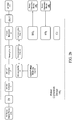
- FIG. 7 illustrates a flow chart of a third application example of the power self-regulation manner of the slave power conversion device 140 1 /140 2 of the smart grid system 100 according to some embodiments of the present invention.
- the slave power conversion device of the smart grid system 100 determines whether the duty ratio of the received duty cycle signal is decreased.
- the slave power conversion device 140 1 determines whether the duty ratio of the first duty cycle signal received by the slave power conversion device 140 1 is decreased.
- the slave power conversion device 140 2 determines whether the duty ratio of the second duty cycle signal received by the slave power conversion device 140 2 is decreased.
- step 4200 when the slave power conversion device determines that the duty ratio of the received duty cycle signal is decreased, the process advances to step 4300.
- step 4400 the slave power conversion device decreases its output power. For example, when the slave power conversion device 140 1 determines that the duty ratio of the first duty cycle signal is decreased, the slave power conversion device 140 1 decreases the output power of the slave power conversion device 140 1 , and the slave power conversion device 140 1 decreases the duty ratio of the second duty cycle signal.
- the slave power conversion device 140 2 determines whether its output power reaches a maximum power of the slave power conversion device, and the process advances to step 4500.
- the slave power conversion device 140 1 determines whether the output power of the slave power conversion device 140 1 reaches a maximum power of the slave power conversion device 140 1 .
- the slave power conversion device 140 2 determines whether the output power of the slave power conversion device 140 2 reaches a maximum power of the slave power conversion device 140 2 .
- step 4500 when the slave power conversion device determines that its output power reaches a maximum power of the slave power conversion device, the slave power conversion device does not adjust its output power.
- the process advances to step 4600.
- step 4600 the slave power conversion device increases its output power. For example, when the slave power conversion device 140 1 determines that the output power of the slave power conversion device 140 1 does not reach a maximum power of the slave power conversion device 140 1 , the slave power conversion device 140 1 increases the output power of the slave power conversion device 140 1 , and the slave power conversion device 140 1 increases the duty ratio of the second duty cycle signal.
- the slave power conversion device 140 2 determines that the output power of the slave power conversion device 140 2 does not reach a maximum power of the slave power conversion device 140 2 , the slave power conversion device 140 2 increases the output power of the slave power conversion device 140 2 .
- the third application example of the power self-regulation manner of the slave power conversion device 140 1 /140 2 of the smart grid system 100 as shown in FIG. 7 describes that the slave power conversion device 140 1 /140 2 adjusts its output power according to the duty ratio of the first/second duty cycle signal and a maximum power of the slave power conversion device 140 1 /140 2 .
- the smart grid system of some embodiments of the present invention allows the output power of each power conversion device to be increased at a relatively slow speed, and the output powers of the power conversion devices can be simultaneous increased at the same time or individually increased in different times.
- the smart grid system of some embodiments of the present invention is required to decrease the output power of each power conversion device at a relatively fast speed, such that the output power of each power conversion device can be decreased immediately.
- the smart grid system of some embodiments of the present invention balances its own power grid through the aforementioned mechanism.
- the present invention discloses a smart grid system and a power management method thereof.
- the master power conversion device is configured, such that the master power conversion device is used as the basis for power dispatching or power management according to the measured current value of the total current flowed through the AC grid, thereby regulating the output power of each of the power conversion devices, so as to realize the control, integration and management of the power information of the smart grid system and comply current regulatory requirements.
Landscapes
- Engineering & Computer Science (AREA)
- Power Engineering (AREA)
- Business, Economics & Management (AREA)
- Health & Medical Sciences (AREA)
- Economics (AREA)
- Strategic Management (AREA)
- Physics & Mathematics (AREA)
- Human Resources & Organizations (AREA)
- Marketing (AREA)
- Primary Health Care (AREA)
- Water Supply & Treatment (AREA)
- Tourism & Hospitality (AREA)
- General Health & Medical Sciences (AREA)
- General Business, Economics & Management (AREA)
- General Physics & Mathematics (AREA)
- Theoretical Computer Science (AREA)
- Public Health (AREA)
- Inverter Devices (AREA)
- Remote Monitoring And Control Of Power-Distribution Networks (AREA)
- Supply And Distribution Of Alternating Current (AREA)
Abstract
Description
- The present invention relates to a smart grid system. More particularly, the present invention relates to a smart grid system and a power management method thereof.
- The known smart grid system requires a monitoring system, such as a remote control system (RCS), to monitor the power trading between the users and the power company, such that the power conversion devices of the users could be regulated by the power company. The aforementioned monitoring system needs to receive the electrical information of the main path measured by the power meter and to analyze the electrical information, and then transmits the corresponding command to each of the power conversion devices of the users through the communication manner (such as RS-485 or WiFi, etc.), such that the power conversion devices of the users could supply power that meets the demand. However, some users do not want to sell electricity (i.e., the supplying power is only for their own use), but the monitoring system is still required to prevent that power conversion device, which is not regulated by the power company, from accidentally supplying power to the power grid. Moreover, during the communication period of each power conversion device, the time delays of transmission, waiting, receiving, and polling are inevitable, and therefore the power conversion devices of the users may not able to respond immediately and thus could not regulate power within the stipulated time, thereby violating current regulatory requirements.
- The present invention provides a smart grid system applied to a load and an AC grid. The smart grid system includes a current sensor and plural power conversion devices. The current sensor is configured to measure a total current flowed through the AC grid and to correspondingly provide a measured current value. The power conversion devices are coupled to the AC grid and configured to supply power to the load. The power conversion devices include a master power conversion device and plural slave power conversion devices. The master power conversion device controls an output power of the master power conversion device and provides a first duty cycle signal according to the measured current value. A first one of the slave power conversion devices which is coupled to the master power conversion device is configured to receive the first duty cycle signal. The first one of the slave power conversion devices controls an output power of the first one of the slave power conversion devices according to the first duty cycle signal. The master power conversion device and the slave power conversion devices are communicated via a daisy chain connection.
- In accordance with one or more embodiments of the invention, the first one of the slave power conversion devices further provides a second duty cycle signal according to the first duty cycle signal.
- In accordance with one or more embodiments of the invention, a second one of the slave power conversion devices which is coupled to the first one of the slave power conversion devices is configured to receive the second duty cycle signal. The second one of the slave power conversion devices controls an output power of the second one of the slave power conversion devices according to the second duty cycle signal.
- In accordance with one or more embodiments of the invention, each of the power conversion devices includes a DC input terminal, an AC output terminal, and a microcontroller. The DC input terminal is configured to receive a DC power. The AC output terminal is configured to output the output power which is an AC power. The microcontroller is configured to control the output power converted from the DC power.
- In accordance with one or more embodiments of the invention, each of the power conversion devices further includes a current measuring terminal. The current measuring terminal of the master power conversion device is configured to receive the measured current value.
- In accordance with one or more embodiments of the invention, the microcontroller of the master power conversion device is configured to control the output power outputted by the AC output terminal of the master power conversion device according to the measured current value.
- In accordance with one or more embodiments of the invention, each of the power conversion devices further includes an I/O (input/output) terminal. The I/O terminal of the master power conversion device is configured to provide the first duty cycle signal. The I/O terminal of the first one of the slave power conversion devices is configured to provide the second duty cycle signal.
- In accordance with one or more embodiments of the invention, the microcontroller of the first one of the slave power conversion devices is configured to control the output power outputted by the AC output terminal of the first one of the slave power conversion devices according to the first duty cycle signal.
- In accordance with one or more embodiments of the invention, the master power conversion device determines a current direction of the total current according to the measured current value, and the master power conversion device controls the output power of the master power conversion device and provides the first duty cycle signal according to the current direction of the total current.
- In accordance with one or more embodiments of the invention, the master power conversion device controls the output power of the master power conversion device and provides the first duty cycle signal by determining whether the measured current value is less than a current setting value.
- The present invention further provides a power management method of a smart grid system. The power management method includes: measuring a total current flowed through a AC grid to provide a measured current value; receiving the measured current value through a master power conversion device of a plurality of power conversion devices coupled to the AC grid, in which the master power conversion device controls an output power of the master power conversion device and provides a first duty cycle signal according to the measured current value; and receiving the first duty cycle signal through a first one of a plurality of slave power conversion devices of the power conversion devices which is coupled to the master power conversion device. The first one of the slave power conversion devices controls an output power of the first one of the slave power conversion devices according to the first duty cycle signal. The power conversion devices are configured to supply power to the load. The master power conversion device and the slave power conversion devices are communicated via a daisy chain connection.
- In accordance with one or more embodiments of the invention, the first one of the slave power conversion devices further provides a second duty cycle signal according to the first duty cycle signal.
- In accordance with one or more embodiments of the invention, the power management method further includes: receiving the second duty cycle signal through a second one of the slave power conversion devices which is coupled to the first one of the slave power conversion devices. The second one of the slave power conversion devices controls an output power of the second one of the slave power conversion devices according to the second duty cycle signal.
- In accordance with one or more embodiments of the invention, the master power conversion device determines a current direction of the total current according to the measured current value, and the master power conversion device controls the output power of the master power conversion device and provides the first duty cycle signal according to the current direction of the total current.
- In accordance with one or more embodiments of the invention, when the current direction of the total current is toward the load, the master power conversion device increases a duty ratio of the first duty cycle signal. When the current direction of the total current is not toward the load, the master power conversion device decreases the duty ratio of the first duty cycle signal.
- In accordance with one or more embodiments of the invention, after increasing or decreasing the duty ratio of the first duty cycle signal, the master power conversion device determines the current direction of the total current again. When the current direction of the total current is toward the load, the master power conversion device does not adjust the duty ratio of the first duty cycle signal. When the current direction of the total current is not toward the load, the master power conversion device decreases the duty ratio of the first duty cycle signal.
- In accordance with one or more embodiments of the invention, the master power conversion device controls the output power of the master power conversion device and provides the first duty cycle signal by determining whether the measured current value is less than a current setting value.
- In accordance with one or more embodiments of the invention, when the measured current value is less than the current setting value, the master power conversion device increases a duty ratio of the first duty cycle signal. When the measured current value is not less than the current setting value, the master power conversion device decreases the duty ratio of the first duty cycle signal.
- In accordance with one or more embodiments of the invention, after increasing or decreasing the duty ratio of the first duty cycle signal, the master power conversion device determines whether the measured current value is less than the current setting value again. When the measured current value is less than the current setting value, the master power conversion device does not adjust the duty ratio of the first duty cycle signal. When the measured current value is not less than the current setting value, the master power conversion device decreases the duty ratio of the first duty cycle signal.
- In accordance with one or more embodiments of the invention, the first one of the slave power conversion devices determines whether the duty ratio of the first duty cycle signal is decreased. When the duty ratio of the first duty cycle signal is decreased, the first one of the slave power conversion devices decreases the output power of the first one of the slave power conversion devices. When the duty ratio of the first duty cycle signal is not decreased, the first one of the slave power conversion devices determines whether the output power of the first one of the slave power conversion devices reaches a maximum power of the first one of the slave power conversion devices. When the output power of the first one of the slave power conversion devices reaches the maximum power of the first one of the slave power conversion devices, the first one of the slave power conversion devices does not adjust the output power of the first one of the slave power conversion devices. When the output power of the first one of the slave power conversion devices does not reach the maximum power of the first one of the slave power conversion devices, the first one of the slave power conversion devices increases the output power of the first one of the slave power conversion devices.
- The invention can be more fully understood by reading the following detailed description of the embodiment, with reference made to the accompanying drawings as follows:
-
FIG. 1 illustrates a block diagram of a smart grid system according to some embodiments of the present invention. -
FIG. 2a illustrates a block diagram of the master power conversion device of the smart grid system according to some embodiments of the present invention. -
FIG. 2b illustrates a block diagram of the slave power conversion device of the smart grid system according to some embodiments of the present invention. -
FIG. 2c illustrates a block diagram of the slave power conversion device of the smart grid system according to some embodiments of the present invention. -
FIG. 3 illustrates a block diagram of the communication manner of the smart grid system according to some embodiments of the present invention. -
FIG. 4 illustrates a flow chart of a power management method of the smart grid system according to some embodiments of the present invention. -
FIG. 5 illustrates a flow chart of a first application example of the power regulating manner of the master power conversion device and the slave power conversion device of the smart grid system according to some embodiments of the present invention. -
FIG. 6 illustrates a flow chart of a second application example of the power regulating manner of the master power conversion device and the slave power conversion device of the smart grid system according to some embodiments of the present invention. -
FIG. 7 illustrates a flow chart of a third application example of the power self-regulation manner of the slave power conversion device of the smart grid system according to some embodiments of the present invention. -
FIG. 1 illustrates a block diagram of asmart grid system 100 according to some embodiments of the present invention. Thesmart grid system 100 includes anAC grid 110, acurrent sensor 120, aload 130, pluralpower conversion devices power source devices - As shown in
FIG. 1 , thepower conversion devices AC grid 110 and coupled to theload 130. In some embodiments of the present invention, theload 130 may be a general appliance load or any load that receives AC power. As shown inFIG. 1 , thepower conversion devices power source devices power source devices power conversion devices power source devices power conversion devices load 130. - As shown in
FIG. 1 , thecurrent sensor 120 is coupled between theAC grid 110 and thepower conversion device 1400. In some embodiments of the present invention, thecurrent sensor 120 may be a current transformer (CT) or a hall sensor, thecurrent sensor 120 is configured to measure a total current flowed through the AC grid 110 (i.e., the current flowed through the main path), thereby providing a measured current value to thepower conversion device 1400. In some embodiments of the present invention, the measured current value provided by thecurrent sensor 120 may be utilized to obtain a current direction of the total current of theAC grid 110. - The
power conversion devices power conversion devices FIG. 2a illustrates a block diagram of the masterpower conversion device 1400 of thesmart grid system 100 according to some embodiments of the present invention.FIG. 2b illustrates a block diagram of the slavepower conversion device 1401 of thesmart grid system 100 according to some embodiments of the present invention.FIG. 2c illustrates a block diagram of the slavepower conversion device 1402 of thesmart grid system 100 according to some embodiments of the present invention. - It is noted that the number of the slave power conversion devices is not limited to two. More particularly, the number of the slave power conversion devices may vary with different application scenarios.
- As shown in
FIGS. 2a ,2b , and2c , each of the master power conversion device 140o and the slavepower conversion devices DC converter 11, a DC-to-AC converter 12, asensing unit 13, a circuit interrupter 14 (e.g., as AC relay), amicrocontroller 15, acommunication unit 16, acommunication port 17, a current/voltage measuring unit 18, two input/output (I/O) terminals I/O1, I/O2, and a current measuring terminal CT. - Each of the master power conversion device 140o and the slave
power conversion devices DC converter 11 of the masterpower conversion device 1400, and the master power conversion device 140o receives the DC power outputted by the DC power source device 150o via the DC input terminals IN of the masterpower conversion device 1400. The DC input terminals IN of the slavepower conversion device 1401 is disposed between the DCpower source device 1501 and the DC-to-DC converter 11 of the slavepower conversion device 1401, and the slavepower conversion device 1401 receives the DC power outputted by the DCpower source device 1501 via the DC input terminals IN of the slavepower conversion device 1401. The DC input terminals IN of the slavepower conversion device 1402 is disposed between the DCpower source device 1502 and the DC-to-DC converter 11 of the slavepower conversion device 1402, and the slavepower conversion device 1401 receives the DC power outputted by the DCpower source device 1501 via the DC input terminals IN of the slavepower conversion device 1401. The AC output terminal OUT of one of the master power conversion device 140o and the slavepower conversion devices AC grid 110 and thecircuit interrupter 14 of the one of the master power conversion device 140o and the slavepower conversion devices power conversion devices AC grid 110 via the AC output terminal OUT of the one of the master power conversion device 140o and the slavepower conversion devices - The DC-to-
DC converter 11 of the one of the master power conversion device 140o and the slavepower conversion devices power conversion device 1400 and the slavepower conversion devices DC converter 11 is used for boosting the DC power. The DC-to-AC converter 12 of the one of the master power conversion device 140o and the slavepower conversion devices DC converter 11 of the one of the master power conversion device 140o and the slavepower conversion devices sensing unit 13 of the one of the master power conversion device 140o and the slavepower conversion devices AC converter 12 of the one of the masterpower conversion device 1400 and the slavepower conversion devices circuit interrupter 14 of the one of the master power conversion device 140o and the slavepower conversion devices power conversion devices AC converter 12 of the one of the masterpower conversion device 1400 and the slavepower conversion devices power conversion devices AC converter 12 of the one of the master power conversion device 140o and the slavepower conversion devices circuit interrupter 14 of the one of the master power conversion device 140o and the slavepower conversion devices power conversion device 1400 and the slavepower conversion devices AC grid 110. - The current/
voltage measuring unit 18 of the one of the masterpower conversion device 1400 and the slavepower conversion devices power conversion device 1400 and the slavepower conversion devices voltage measuring unit 18 of the one of the masterpower conversion device 1400 and the slavepower conversion devices microcontroller 15 of the one of the masterpower conversion device 1400 and the slavepower conversion devices microcontroller 15 of the one of the masterpower conversion device 1400 and the slavepower conversion devices power conversion device 1400 and the slavepower conversion devices - The
microcontroller 15 may be one of a micro control unit (MCU), a microprocessor unit (MPU), an application-specific integrated circuit (ASIC), and a system on a chip (SoC). - The conventional smart grid system provides the aforementioned power information (or the current/voltage information) to the monitoring system, such as a remote control system (RCS), via the
communication unit 16 of each of the power conversion devices. Thecommunication unit 16 is connected to the monitoring system via a wireless communication manner (e.g., WiFi) or a wired communication manner (e.g., RS-485 or CAN bus). Therefore, the power conversion devices are communicated with the management center (e.g., a private-owned or state-owned power company or a power business organization), and thus the management center may perform electric power dispatching or electric power management, thereby realizing the control, integration and management of the power information of the smart grid system. However, some users do not want to sell electricity (i.e., the supplying power is only for their own use), in such case, for the communication manner of the conventional smart grid system, the time delays of transmission, waiting, receiving, and polling are inevitable during the period of communication, and therefore the power company may not able to respond immediately and thus could not regulate power within the stipulated time, thereby violating current regulatory requirements. -
FIG. 3 illustrates a block diagram of the communication manner of thesmart grid system 100 according to some embodiments of the present invention. As shown inFIG. 3 , the master power conversion device 140o and the slavepower conversion devices power conversion device 1400 is serially connected to the slavepower conversion device 1401 through the I/O terminal I/O2 of the masterpower conversion device 1400 and the I/O terminal I/O1 of the slavepower conversion device 1401, and the slavepower conversion device 1401 is sequentially serially connected to the slavepower conversion device 1402 through the I/O terminal I/O2 of the slavepower conversion device 1401 and the I/O terminal I/O1 of the slavepower conversion device 1402. Referring toFIGS. 2a ,2b ,2c , and3 , in some embodiments of the present invention, the current measuring terminal CT of the masterpower conversion device 1400 is configured to receive the measured current value measured by thecurrent sensor 120. Themicrocontroller 15 of the masterpower conversion device 1400 is configured to control/regulate the output power of the masterpower conversion device 1400 according to the measured current value outputted by thecurrent sensor 120. In addition, themicrocontroller 15 of the masterpower conversion device 1400 is further configured to provide a first duty cycle signal (through the I/O terminal I/O2 of the master power conversion device 1400) to the slavepower conversion device 1401 which is connected to the masterpower conversion device 1400 according to the measured current value outputted by thecurrent sensor 120. - The I/O terminal I/O1 of the slave
power conversion device 1401 is configured to receive the first duty cycle signal provided by the masterpower conversion device 1400, and themicrocontroller 15 of the slavepower conversion device 1401 is configured to control/regulate the output power of the slavepower conversion device 1401 according to the first duty cycle signal. In addition, themicrocontroller 15 of the slavepower conversion device 1401 is further configured to provide a second duty cycle signal (through the I/O terminal I/O2 of the slave power conversion device 1401) to the slavepower conversion device 1402 which is connected to the slavepower conversion device 1401 according to the first duty cycle signal. - The I/O terminal I/O1 of the slave
power conversion device 1402 is configured to receive the second duty cycle signal provided by the slavepower conversion device 1401, and themicrocontroller 15 of the slavepower conversion device 1402 is configured to control/regulate the output power of the slavepower conversion device 1402 according to the second duty cycle signal. - In some embodiments of the present invention, each of the aforementioned first duty cycle signal and the aforementioned second duty cycle signal is square wave signal with 0% to 100% duty ratio (i.e., duty cycle), and the aforementioned square wave signal is generated by modulating a square wave with pulse width modulation. In some embodiments of the present invention, the output power of the slave
power conversion device 1401 increase with the duty ratio of the first duty cycle signal. In other words, when the masterpower conversion device 1400 increases the duty ratio of the first duty cycle signal, the output power of the slavepower conversion device 1401 increases accordingly; when the masterpower conversion device 1400 decreases the duty ratio of the first duty cycle signal, the output power of the slavepower conversion device 1401 decreases accordingly. In some embodiments of the present invention, the output power of the slavepower conversion device 1402 increase with the duty ratio of the second duty cycle signal. In other words, when the slavepower conversion device 1401 increases the duty ratio of the second duty cycle signal, the output power of the slavepower conversion device 1402 increases accordingly; when the slavepower conversion device 1401 decreases the duty ratio of the second duty cycle signal, the output power of the slavepower conversion device 1402 decreases accordingly. However, the trends between the duty ratio of the first/second duty cycle signal and the output power are not limited thereto, for example, the opposite configuration may be set, that is, the greater the duty ratio of the first/second duty cycle signal, the lower the output power. - In comparison with the conventional smart grid system, the
smart grid system 100 of some embodiments of the present invention does not require an additional monitoring system to monitor the electrical information of the main path and to perform electric power dispatching on each power conversion device through the WiFi communication manner, the RS-485 communication manner, or the CAN bus communication manner. That is, thesmart grid system 100 of some embodiments of the present invention does not need to configure complicated peripheral lines, and thus thesmart grid system 100 can not only reduce the cost for installing the smart grid system, but also reduce the labor costs and time costs for maintaining the smart grid system. Thesmart grid system 100 reduces the dense line configuration, thereby reducing the electromagnetic interference and reducing the loss of power transmission. That is, thesmart grid system 100 can save labor costs and time costs, and thesmart grid system 100 can simplify the configuration of peripheral lines, and thesmart grid system 100 can reduce the electromagnetic interference, and thesmart grid system 100 can reduce the hardware costs. - In addition, in comparison with the conventional smart grid system, the
smart grid system 100 of some embodiments of the present invention does not transmit commands to each power conversion device via the monitoring system through WiFi communication manner, the RS-485 communication manner, or the CAN bus communication manner. The masterpower conversion device 1400 and the slavepower conversion devices smart grid system 100 are communicated via the daisy chain connection. The masterpower conversion device 1400 and the slavepower conversion devices smart grid system 100 transmit commands (i.e., the first/second duty cycle signal) through the corresponding I/O terminal(s) I/O1 and/or I/O2 via the daisy chain connection. This daisy chain communication manner is independent for two adjacent power conversion devices, and the transmitted command is provided by the previous power conversion device, thereby avoiding redundancy time delays of transmission, waiting, receiving, and polling during the communication period. Specifically, thesmart grid system 100 has a relatively less time delay, such that the power company may be able to respond immediately and could regulate power within the stipulated time, thereby complying current regulatory requirements. -
FIG. 4 illustrates a flow chart of apower management method 1000 of thesmart grid system 100 according to some embodiments of the present invention. Referring toFIG. 1 andFIG. 4 , thepower management method 1000 includes steps 1100-1400. Instep 1100, thecurrent sensor 120 of thesmart grid system 100 measures the total current flowed through theAC grid 110 and to correspondingly provides the measured current value. Then, instep 1200, the masterpower conversion device 1400 receives the measured current value measured from thecurrent sensor 120, and the masterpower conversion device 1400 controls the output power of the masterpower conversion device 1400 according to the measured current value outputted by thecurrent sensor 120, and the masterpower conversion device 1400 provides the first duty cycle signal to the slavepower conversion device 1401 which is connected to the masterpower conversion device 1400 according to the measured current value outputted by thecurrent sensor 120. Then, instep 1300, the slavepower conversion device 1401 receives the first duty cycle signal provided by the masterpower conversion device 1400, and the slavepower conversion device 1401 controls the output power of the slavepower conversion device 1401 according to the first duty cycle signal, and the slavepower conversion device 1401 further provides the second duty cycle signal to the slavepower conversion device 1402 which is connected to the slavepower conversion device 1401 according to the first duty cycle signal. Then, instep 1400, the slavepower conversion device 1402 receives the second duty cycle signal provided by the slavepower conversion device 1401, and the slavepower conversion device 1402 controls the output power of the slavepower conversion device 1402 according to the second duty cycle signal. -
FIG. 5 illustrates a flow chart of a first application example of the power regulating manner of the masterpower conversion device 1400 and the slavepower conversion device 1401 of thesmart grid system 100 according to some embodiments of the present invention. As shown inFIG. 5 , instep 2100, the masterpower conversion device 1400 receives the measured current value from thecurrent sensor 120 of thesmart grid system 100, and the masterpower conversion device 1400 determines the current direction of the total current flowed through theAC grid 110 according to the measured current value. Then, instep 2200, the masterpower conversion device 1400 determines whether the current direction of the total current flowed through theAC grid 110 is toward theload 130. If the current direction of the total current flowed through theAC grid 110 is toward theload 130, it can be understood that the electric output power provided by all of the power conversion devices is not enough for theload 130. When the masterpower conversion device 1400 determines that the current direction of the total current flowed through theAC grid 110 is toward theload 130, the process advances to step 2300. When the masterpower conversion device 1400 determines that the current direction of the total current flowed through theAC grid 110 is not toward theload 130, the process advances to step 2400. Instep 2300, the masterpower conversion device 1400 increases the output power of the masterpower conversion device 1400, and the masterpower conversion device 1400 increases the duty ratio of the first duty cycle signal such that the output power of the slavepower conversion device 1401 increases correspondingly, and then the process advances to step 2500. Instep 2400, the masterpower conversion device 1400 decreases the output power of the masterpower conversion device 1400, and the masterpower conversion device 1400 decreases the duty ratio of the first duty cycle signal such that the output power of the slavepower conversion device 1401 decreases correspondingly, and then the process advances to step 2500. Instep 2500, the masterpower conversion device 1400 receives the measured current value from thecurrent sensor 120 again, and the masterpower conversion device 1400 determines the current direction of the total current flowed through theAC grid 110 according to the measured current value again. Then, instep 2600, the masterpower conversion device 1400 determines whether the current direction of the total current flowed through theAC grid 110 is toward theload 130 again. When the masterpower conversion device 1400 determines that the current direction of the total current flowed through theAC grid 110 is toward theload 130, the masterpower conversion device 1400 does not adjust the duty ratio of the first duty cycle signal. When the masterpower conversion device 1400 determines that the current direction of the total current flowed through theAC grid 110 is not toward theload 130, the process returns to step 2400. - Specifically, the first application example of the power regulating manner of the master
power conversion device 1400 and the slavepower conversion device 1401 of thesmart grid system 100 as shown inFIG. 5 is an application example that the output power outputted by the power conversion device(s) is only supplied to theload 130 and not supplied to theAC grid 110. That is, the first application example is an application example for self-regulation that the users do not want to sell electricity (i.e., the supplying power is only for their own use). In this first application example, the masterpower conversion device 1400 controls the output power of the masterpower conversion device 1400 according to the current direction of the total current flowed through theAC grid 110. Moreover, the masterpower conversion device 1400 adjusts the duty ratio of the first duty cycle signal according to the current direction of the total current flowed through theAC grid 110, thereby regulating the output power of the slavepower conversion device 1401. -
FIG. 6 illustrates a flow chart of a second application example of the power regulating manner of the masterpower conversion device 1400 and the slavepower conversion device 1401 of thesmart grid system 100 according to some embodiments of the present invention. As shown inFIG. 6 , instep 3100, the masterpower conversion device 1400 receives the measured current value from thecurrent sensor 120 of thesmart grid system 100, and the masterpower conversion device 1400 determines whether the measured current value is less than a current setting value. The current setting value is, for example, a current threshold value set by the operator or a current threshold value transmitted to the masterpower conversion device 1400 through any device. Then, instep 3200, when the masterpower conversion device 1400 determines that the measured current value is less than the current setting value, the process advances to step 3300. When the masterpower conversion device 1400 determines that the measured current value is not less than the current setting value, the process advances to step 3400. Instep 3300, the masterpower conversion device 1400 increases the output power of the masterpower conversion device 1400, and the masterpower conversion device 1400 increases the duty ratio of the first duty cycle signal such that the output power of the slavepower conversion device 1401 increases correspondingly, and then the process advances to step 3500. Instep 3400, the masterpower conversion device 1400 decreases the output power of the masterpower conversion device 1400, and the masterpower conversion device 1400 decreases the duty ratio of the first duty cycle signal such that the output power of the slavepower conversion device 1401 decreases correspondingly, and then the process advances to step 3500. Instep 3500, the masterpower conversion device 1400 receives the measured current value from thecurrent sensor 120 again, and the masterpower conversion device 1400 determines whether the measured current value is less than the current setting value again. Then, instep 3600, when the masterpower conversion device 1400 determines that the measured current value is less than the current setting value, the masterpower conversion device 1400 does not adjust the duty ratio of the first duty cycle signal. When the masterpower conversion device 1400 determines that the measured current value is not less than the current setting value, the process returns to step 3400. - Specifically, the second application example of the power regulating manner of the master
power conversion device 1400 and the slavepower conversion device 1401 of thesmart grid system 100 as shown inFIG. 6 is an application example that thesmart grid system 100 limits the energy outputted to theAC grid 110 by setting the current setting value. In other words, the second application example is an application example that the output power outputted by the power conversion device is allowed to supply toAC grid 110. That is, the second application example is an application example for self-regulation that the users sell electricity to the power company. In this second application example, the masterpower conversion device 1400 controls the output power of the masterpower conversion device 1400 by determining whether the measured current value is less than the current setting value. Moreover, the masterpower conversion device 1400 adjusts the duty ratio of the first duty cycle signal by determining whether the measured current value is less than the current setting value, thereby regulating the output power of the slavepower conversion device 1401. The difference between the first application example and the second application example is the corresponding current setting value. The first application example sets the current setting value, thereby avoiding the output power supplied to theAC grid 100. The second application example adjusts the current setting value according to the requirement, thereby allowing the output power supplies to theAC grid 100. -
FIG. 7 illustrates a flow chart of a third application example of the power self-regulation manner of the slavepower conversion device 1401/1402 of thesmart grid system 100 according to some embodiments of the present invention. As shown inFIG. 7 , instep 4100, the slave power conversion device of thesmart grid system 100 determines whether the duty ratio of the received duty cycle signal is decreased. For example, the slavepower conversion device 1401 determines whether the duty ratio of the first duty cycle signal received by the slavepower conversion device 1401 is decreased. For example, the slavepower conversion device 1402 determines whether the duty ratio of the second duty cycle signal received by the slavepower conversion device 1402 is decreased. Then, instep 4200, when the slave power conversion device determines that the duty ratio of the received duty cycle signal is decreased, the process advances to step 4300. When the slave power conversion device determines that the duty ratio of the received duty cycle signal is not decreased, the process advances to step 4400. Instep 4300, the slave power conversion device decreases its output power. For example, when the slavepower conversion device 1401 determines that the duty ratio of the first duty cycle signal is decreased, the slavepower conversion device 1401 decreases the output power of the slavepower conversion device 1401, and the slavepower conversion device 1401 decreases the duty ratio of the second duty cycle signal. For example, when the slavepower conversion device 1402 determines that the duty ratio of the second duty cycle signal is decreased, the slavepower conversion device 1402 decreases the output power of the slavepower conversion device 1402. Instep 4400, the slave power conversion device determines whether its output power reaches a maximum power of the slave power conversion device, and the process advances to step 4500. For example, the slavepower conversion device 1401 determines whether the output power of the slavepower conversion device 1401 reaches a maximum power of the slavepower conversion device 1401. For example, the slavepower conversion device 1402 determines whether the output power of the slavepower conversion device 1402 reaches a maximum power of the slavepower conversion device 1402. Instep 4500, when the slave power conversion device determines that its output power reaches a maximum power of the slave power conversion device, the slave power conversion device does not adjust its output power. When the slave power conversion device determines that its output power does not reach a maximum power of the slave power conversion device, the process advances to step 4600. Instep 4600, the slave power conversion device increases its output power. For example, when the slavepower conversion device 1401 determines that the output power of the slavepower conversion device 1401 does not reach a maximum power of the slavepower conversion device 1401, the slavepower conversion device 1401 increases the output power of the slavepower conversion device 1401, and the slavepower conversion device 1401 increases the duty ratio of the second duty cycle signal. For example, when the slavepower conversion device 1402 determines that the output power of the slavepower conversion device 1402 does not reach a maximum power of the slavepower conversion device 1402, the slavepower conversion device 1402 increases the output power of the slavepower conversion device 1402. - Specifically, the third application example of the power self-regulation manner of the slave
power conversion device 1401/1402 of thesmart grid system 100 as shown inFIG. 7 describes that the slavepower conversion device 1401/1402 adjusts its output power according to the duty ratio of the first/second duty cycle signal and a maximum power of the slavepower conversion device 1401/1402. - It is worth mentioning that, in some embodiments of the present invention, in order to comply current regulatory requirements, the output power of each power conversion device needs to be decreased within a stipulated time, such that the output power of each power conversion device is not supplied to the AC grid. Therefore, the smart grid system of some embodiments of the present invention allows the output power of each power conversion device to be increased at a relatively slow speed, and the output powers of the power conversion devices can be simultaneous increased at the same time or individually increased in different times. However, in order to comply current regulatory requirements, the smart grid system of some embodiments of the present invention is required to decrease the output power of each power conversion device at a relatively fast speed, such that the output power of each power conversion device can be decreased immediately. The smart grid system of some embodiments of the present invention balances its own power grid through the aforementioned mechanism.
- From the above description, the present invention discloses a smart grid system and a power management method thereof. The master power conversion device is configured, such that the master power conversion device is used as the basis for power dispatching or power management according to the measured current value of the total current flowed through the AC grid, thereby regulating the output power of each of the power conversion devices, so as to realize the control, integration and management of the power information of the smart grid system and comply current regulatory requirements.
Claims (15)
- A smart grid system (100), applied to a load (130) and an AC grid (110), wherein the smart grid system (100) comprises:a current sensor (120) configured to measure a total current flowed through the AC grid (110) and to correspondingly provide a measured current value; anda plurality of power conversion devices (1400, 1401, 1402) coupled to the AC grid (110) and configured to supply power to the load (130), wherein the power conversion devices (1400, 1401, 1402) comprise:a master power conversion device (1400) configured to receive the measured current value, wherein the master power conversion device (1400) controls an output power of the master power conversion device (1400) and provides a first duty cycle signal according to the measured current value; anda plurality of slave power conversion devices (1401, 1402), wherein a first one of the slave power conversion devices (1401) which is coupled to the master power conversion device (1400) is configured to receive the first duty cycle signal, wherein the first one of the slave power conversion devices (1401) controls an output power of the first one of the slave power conversion devices (1401) according to the first duty cycle signal;wherein the master power conversion device (1400) and the slave power conversion devices (1401, 1402) are communicated via a daisy chain connection.
- The smart grid system of claim 1, wherein the first one of the slave power conversion devices (1401) further provides a second duty cycle signal according to the first duty cycle signal.
- The smart grid system of claim 2, wherein a second one of the slave power conversion devices (1402) which is coupled to the first one of the slave power conversion devices (1401) is configured to receive the second duty cycle signal, wherein the second one of the slave power conversion devices (1402) controls an output power of the second one of the slave power conversion devices (1402) according to the second duty cycle signal.
- The smart grid system of claim 2, wherein each of the power conversion devices (1400, 1401, 1402) comprises:a DC input terminal (IN) configured to receive a DC power;an AC output terminal (OUT) configured to output the output power, wherein the output power is an AC power; anda microcontroller (15) configured to control the output power converted from the DC power.
- The smart grid system of claim 4, wherein each of the power conversion devices (1400, 1401, 1402) further comprises:a current measuring terminal (CT), where the current measuring terminal (CT) of the master power conversion device (1400) is configured to receive the measured current value; andan I/O (input/output) terminal (I/O2), wherein the I/O terminal (I/O2) of the master power conversion device (1400) is configured to provide the first duty cycle signal, wherein the I/O terminal (I/O2) of the first one of the slave power conversion devices (1401) is configured to provide the second duty cycle signal.
- The smart grid system of claim 4,
wherein the microcontroller (15) of the master power conversion device (1400) is configured to control the output power outputted by the AC output terminal (OUT) of the master power conversion device (1400) according to the measured current value;
wherein the microcontroller (15) of the first one of the slave power conversion devices (1401) is configured to control the output power outputted by the AC output terminal (OUT) of the first one of the slave power conversion devices (1401) according to the first duty cycle signal. - The smart grid system of claim 1, wherein the master power conversion device (1400) determines a current direction of the total current according to the measured current value, and the master power conversion device (1400) controls the output power of the master power conversion device (1400) and provides the first duty cycle signal according to the current direction of the total current.
- The smart grid system of claim 1, wherein the master power conversion device (1400) controls the output power of the master power conversion device (1400) and provides the first duty cycle signal by determining whether the measured current value is less than a current setting value.
- A power management method (1000) of a smart grid system (100), comprising:measuring a total current flowed through a AC grid (110) to provide a measured current value;receiving the measured current value through a master power conversion device (1400) of a plurality of power conversion devices (1400, 1401, 1402) coupled to the AC grid (110), wherein the master power conversion device (1400) controls an output power of the master power conversion device (1400) and provides a first duty cycle signal according to the measured current value; andreceiving the first duty cycle signal through a first one of a plurality of slave power conversion devices of the power conversion devices (1401) which is coupled to the master power conversion device (1400), wherein the first one of the slave power conversion devices (1401) controls an output power of the first one of the slave power conversion devices (1401) according to the first duty cycle signal;wherein the power conversion devices (1400, 1401, 1402) are configured to supply power to a load (130), wherein the master power conversion device (1400) and the slave power conversion devices (1401, 1402) are communicated via a daisy chain connection.
- The power management method of claim 9, wherein the first one of the slave power conversion devices (1401) further provides a second duty cycle signal according to the first duty cycle signal.
- The power management method of claim 10, further comprising:
receiving the second duty cycle signal through a second one of the slave power conversion devices (1402) which is coupled to the first one of the slave power conversion devices (1401), wherein the second one of the slave power conversion devices (1402) controls an output power of the second one of the slave power conversion devices (1402) according to the second duty cycle signal. - The power management method of claim 9,
wherein the master power conversion device (1400) determines a current direction of the total current according to the measured current value, and the master power conversion device (1400) controls the output power of the master power conversion device (1400) and provides the first duty cycle signal according to the current direction of the total current;
when the current direction of the total current is toward the load (130), the master power conversion device (1400) increases a duty ratio of the first duty cycle signal;
when the current direction of the total current is not toward the load (130), the master power conversion device (1400) decreases the duty ratio of the first duty cycle signal;
after increasing or decreasing the duty ratio of the first duty cycle signal, the master power conversion device (1400) determines the current direction of the total current again;
when the current direction of the total current is toward the load (130), the master power conversion device (1400) does not adjust the duty ratio of the first duty cycle signal;
when the current direction of the total current is not toward the load (130), the master power conversion device (1400) decreases the duty ratio of the first duty cycle signal. - The power management method of claim 9, wherein the master power conversion device (1400) controls the output power of the master power conversion device (1400) and provides the first duty cycle signal by determining whether the measured current value is less than a current setting value.
- The power management method of claim 13, wherein
when the measured current value is less than the current setting value, the master power conversion device (1400) increases a duty ratio of the first duty cycle signal;
when the measured current value is not less than the current setting value, the master power conversion device (1400) decreases the duty ratio of the first duty cycle signal;
after increasing or decreasing the duty ratio of the first duty cycle signal, the master power conversion device (1400) determines whether the measured current value is less than the current setting value again;
when the measured current value is less than the current setting value, the master power conversion device (1400) does not adjust the duty ratio of the first duty cycle signal;
when the measured current value is not less than the current setting value, the master power conversion device (1400) decreases the duty ratio of the first duty cycle signal. - The power management method of claim 14, wherein the first one of the slave power conversion devices (1401) determines whether the duty ratio of the first duty cycle signal is decreased;
when the duty ratio of the first duty cycle signal is decreased, the first one of the slave power conversion devices (1401) decreases the output power of the first one of the slave power conversion devices (1401);
when the duty ratio of the first duty cycle signal is not decreased, the first one of the slave power conversion devices (1401) determines whether the output power of the first one of the slave power conversion devices (1401) reaches a maximum power of the first one of the slave power conversion devices (1401);
when the output power of the first one of the slave power conversion devices (1401) reaches the maximum power of the first one of the slave power conversion devices (1401), the first one of the slave power conversion devices (1401) does not adjust the output power of the first one of the slave power conversion devices (1401);
when the output power of the first one of the slave power conversion devices (1401) does not reach the maximum power of the first one of the slave power conversion devices (1401), the first one of the slave power conversion devices (1401) increases the output power of the first one of the slave power conversion devices (1401).
Applications Claiming Priority (1)
| Application Number | Priority Date | Filing Date | Title |
|---|---|---|---|
| CN202010144066.3A CN113364114A (en) | 2020-03-04 | 2020-03-04 | Smart power grid system and power management method thereof |
Publications (1)
| Publication Number | Publication Date |
|---|---|
| EP3876379A1 true EP3876379A1 (en) | 2021-09-08 |
Family
ID=74194580
Family Applications (1)
| Application Number | Title | Priority Date | Filing Date |
|---|---|---|---|
| EP21152564.7A Pending EP3876379A1 (en) | 2020-03-04 | 2021-01-20 | Smart grid system and power management method thereof |
Country Status (4)
| Country | Link |
|---|---|
| US (1) | US11381087B2 (en) |
| EP (1) | EP3876379A1 (en) |
| JP (1) | JP7014362B2 (en) |
| CN (1) | CN113364114A (en) |
Citations (4)
| Publication number | Priority date | Publication date | Assignee | Title |
|---|---|---|---|---|
| US20100013306A1 (en) * | 2008-07-18 | 2010-01-21 | Heineman Douglas E | Intelligent Management of Current Sharing Group |
| US20130026839A1 (en) * | 2011-07-28 | 2013-01-31 | Tigo Energy, Inc. | Systems and Methods to Combine Strings of Solar Panels |
| WO2016004433A1 (en) * | 2014-07-04 | 2016-01-07 | Apparent Inc | Grid network gateway aggregation |
| US20160079757A1 (en) * | 2014-07-04 | 2016-03-17 | Stefan Matan | Distributed power grid control with local var generation |
Family Cites Families (27)
| Publication number | Priority date | Publication date | Assignee | Title |
|---|---|---|---|---|
| JP2006109258A (en) * | 2004-10-07 | 2006-04-20 | Hitachi Ltd | Communication method and communication apparatus |
| JP4791383B2 (en) * | 2007-01-25 | 2011-10-12 | 株式会社ダイヘン | Grid-connected inverter system and power control method for grid-connected inverter system |
| US8693228B2 (en) | 2009-02-19 | 2014-04-08 | Stefan Matan | Power transfer management for local power sources of a grid-tied load |
| US8810217B2 (en) * | 2009-04-01 | 2014-08-19 | Telefonaktiebolaget L M Ericsson (Publ) | Current share configuration in a power converter system |
| US20120091817A1 (en) | 2010-10-18 | 2012-04-19 | Advanced Energy Industries, Inc. | System, method, and apparatus for ac grid connection of series-connected inverters |
| TW201306435A (en) | 2011-07-21 | 2013-02-01 | Univ Nat Cheng Kung | Photovoltaic power apparatus and photovoltaic power system |
| CN104659804B (en) | 2013-11-20 | 2017-03-08 | 沈阳工业大学 | Micro-capacitance sensor containing hybrid energy-storing and its control method |
| JP2015198458A (en) * | 2014-03-31 | 2015-11-09 | ミツミ電機株式会社 | Inverter system and parallel synchronous operation control method for a plurality of inverters |
| JP6358859B2 (en) * | 2014-06-04 | 2018-07-18 | 東芝機械株式会社 | Inverter power generation system and inverter power generation device |
| US11063431B2 (en) | 2014-07-04 | 2021-07-13 | Apparent Labs Llc | Hierarchical and distributed power grid control |
| WO2016006257A1 (en) * | 2014-07-10 | 2016-01-14 | 京セラ株式会社 | Power generation device, power generation system and power generation method |
| EP3200307A4 (en) * | 2014-09-26 | 2018-04-25 | Kyocera Corporation | Power supply device, power supply system, and power supply method |
| JP6424565B2 (en) * | 2014-10-28 | 2018-11-21 | 株式会社ノーリツ | Power conditioner |
| US9871379B2 (en) | 2015-02-18 | 2018-01-16 | Cyboenergy, Inc. | Smart microgrids and dual-output off-grid power inverters with DC source flexibility |
| MX2017014244A (en) * | 2015-05-08 | 2019-02-26 | Solpad Inc | Solar power generation, distribution, and communication system. |
| JP6503060B2 (en) * | 2015-05-26 | 2019-04-17 | 京セラ株式会社 | POWER GENERATOR, POWER GENERATING SYSTEM, AND CONTROL METHOD OF POWER GENERATING SYSTEM |
| JP6425625B2 (en) * | 2015-06-29 | 2018-11-21 | 新電元工業株式会社 | Distributed power supply |
| US10050445B2 (en) | 2015-07-13 | 2018-08-14 | Sparq Systems Inc. | PV inverter with micro/nano-grid integration capability |
| US10305286B2 (en) | 2015-08-14 | 2019-05-28 | Solarcity Corporation | Multiple inverter power control systems in an energy generation system |
| JP6720056B2 (en) * | 2016-11-10 | 2020-07-08 | 株式会社ダイヘン | Power supply system and power supply |
| JP2018098838A (en) * | 2016-12-08 | 2018-06-21 | 日立化成株式会社 | Power supply system |
| TWM579410U (en) | 2019-01-08 | 2019-06-11 | 台達電子工業股份有限公司 | Power conversion apparatus and smart grid system having the same |
| CN111416431A (en) * | 2019-01-08 | 2020-07-14 | 台达电子工业股份有限公司 | Smart grid integration system and power information processing method |
| CN109462236B (en) * | 2019-01-11 | 2022-10-04 | 新风光电子科技股份有限公司 | APF parallel operation system and method based on high-speed serial optical fiber |
| TWI728728B (en) * | 2020-03-04 | 2021-05-21 | 台達電子工業股份有限公司 | Smart grid system and power management method thereof |
| CN111313665B (en) * | 2020-03-16 | 2021-10-15 | 成都芯源系统有限公司 | Multiphase switching converter, control circuit thereof and fault protection method |
| CN112838619B (en) * | 2020-12-30 | 2023-03-28 | 山东大学 | Energy storage converter parallel operation system and method based on high-speed serial optical fiber |
-
2020
- 2020-03-04 CN CN202010144066.3A patent/CN113364114A/en active Pending
- 2020-09-17 US US17/023,408 patent/US11381087B2/en active Active
- 2020-11-26 JP JP2020196269A patent/JP7014362B2/en active Active
-
2021
- 2021-01-20 EP EP21152564.7A patent/EP3876379A1/en active Pending
Patent Citations (4)
| Publication number | Priority date | Publication date | Assignee | Title |
|---|---|---|---|---|
| US20100013306A1 (en) * | 2008-07-18 | 2010-01-21 | Heineman Douglas E | Intelligent Management of Current Sharing Group |
| US20130026839A1 (en) * | 2011-07-28 | 2013-01-31 | Tigo Energy, Inc. | Systems and Methods to Combine Strings of Solar Panels |
| WO2016004433A1 (en) * | 2014-07-04 | 2016-01-07 | Apparent Inc | Grid network gateway aggregation |
| US20160079757A1 (en) * | 2014-07-04 | 2016-03-17 | Stefan Matan | Distributed power grid control with local var generation |
Also Published As
| Publication number | Publication date |
|---|---|
| US11381087B2 (en) | 2022-07-05 |
| JP7014362B2 (en) | 2022-02-01 |
| US20210281075A1 (en) | 2021-09-09 |
| CN113364114A (en) | 2021-09-07 |
| JP2021141794A (en) | 2021-09-16 |
Similar Documents
| Publication | Publication Date | Title |
|---|---|---|
| US11239694B2 (en) | Multi-port power delivery | |
| EP3609038B1 (en) | Device to be charged, wireless charging apparatus, wireless charging method and system | |
| US10913370B2 (en) | Power supply system and method of operating power supply between power distribution branch for household appliances and charging branch for electric vehicle | |
| KR20160081067A (en) | Low Voltage DC Distribution System and Distribution Method thereof | |
| CN103493323A (en) | Control of dynamic bus voltage in an intermediate bus architecture power system | |
| US11496052B2 (en) | Insulated power supply circuit | |
| CN106160249A (en) | Wireless power receives device and includes that wireless power receives the electronic installation of device | |
| US11581797B2 (en) | Multiple outputs universal serial bus travel adaptor and control method thereof | |
| WO2018180889A1 (en) | Power conversion device, power conversion system, and dc power supply device | |
| US11711017B2 (en) | Adapter and control method thereof | |
| EP2159896B1 (en) | Electrical system and method of operating such a system | |
| US11381087B2 (en) | Smart grid system and power management method thereof | |
| TWI728728B (en) | Smart grid system and power management method thereof | |
| CN111525676A (en) | DC output uninterruptible power supply | |
| JP6646790B1 (en) | DC power network system, DC / DC converter device and control method therefor | |
| JP2024097339A (en) | Configuration System | |
| AU2016293631B2 (en) | Storage battery control system, storage battery control method, and program | |
| KR101149315B1 (en) | Integrated power supply for substation | |
| CN111316522A (en) | Voltage droop-based approach in power transmission systems | |
| CN119482878B (en) | Self-adaptive power adapter and adjusting method thereof | |
| CN215601078U (en) | Intelligent power supply and charger | |
| CN111049384A (en) | Low-power-consumption power conversion circuit for control panel | |
| CN117175765B (en) | Solar controller, control method and photovoltaic control system | |
| JP7603868B1 (en) | Power supply system and power supply method | |
| US11292357B2 (en) | Intelligent current control apparatus |
Legal Events
| Date | Code | Title | Description |
|---|---|---|---|
| PUAI | Public reference made under article 153(3) epc to a published international application that has entered the european phase |
Free format text: ORIGINAL CODE: 0009012 |
|
| STAA | Information on the status of an ep patent application or granted ep patent |
Free format text: STATUS: THE APPLICATION HAS BEEN PUBLISHED |
|
| AK | Designated contracting states |
Kind code of ref document: A1 Designated state(s): AL AT BE BG CH CY CZ DE DK EE ES FI FR GB GR HR HU IE IS IT LI LT LU LV MC MK MT NL NO PL PT RO RS SE SI SK SM TR |
|
| STAA | Information on the status of an ep patent application or granted ep patent |
Free format text: STATUS: REQUEST FOR EXAMINATION WAS MADE |
|
| 17P | Request for examination filed |
Effective date: 20220307 |
|
| RBV | Designated contracting states (corrected) |
Designated state(s): AL AT BE BG CH CY CZ DE DK EE ES FI FR GB GR HR HU IE IS IT LI LT LU LV MC MK MT NL NO PL PT RO RS SE SI SK SM TR |