WO2016047146A1 - Power supply device, power supply system, and power supply method - Google Patents
Power supply device, power supply system, and power supply method Download PDFInfo
- Publication number
- WO2016047146A1 WO2016047146A1 PCT/JP2015/004875 JP2015004875W WO2016047146A1 WO 2016047146 A1 WO2016047146 A1 WO 2016047146A1 JP 2015004875 W JP2015004875 W JP 2015004875W WO 2016047146 A1 WO2016047146 A1 WO 2016047146A1
- Authority
- WO
- WIPO (PCT)
- Prior art keywords
- fuel cell
- cell module
- output
- power
- power supply
- Prior art date
Links
Images


Classifications
-
- H—ELECTRICITY
- H01—ELECTRIC ELEMENTS
- H01M—PROCESSES OR MEANS, e.g. BATTERIES, FOR THE DIRECT CONVERSION OF CHEMICAL ENERGY INTO ELECTRICAL ENERGY
- H01M8/00—Fuel cells; Manufacture thereof
- H01M8/04—Auxiliary arrangements, e.g. for control of pressure or for circulation of fluids
- H01M8/04298—Processes for controlling fuel cells or fuel cell systems
- H01M8/04694—Processes for controlling fuel cells or fuel cell systems characterised by variables to be controlled
- H01M8/04858—Electric variables
- H01M8/04925—Power, energy, capacity or load
- H01M8/0494—Power, energy, capacity or load of fuel cell stacks
-
- H—ELECTRICITY
- H01—ELECTRIC ELEMENTS
- H01M—PROCESSES OR MEANS, e.g. BATTERIES, FOR THE DIRECT CONVERSION OF CHEMICAL ENERGY INTO ELECTRICAL ENERGY
- H01M8/00—Fuel cells; Manufacture thereof
- H01M8/04—Auxiliary arrangements, e.g. for control of pressure or for circulation of fluids
- H01M8/04298—Processes for controlling fuel cells or fuel cell systems
- H01M8/043—Processes for controlling fuel cells or fuel cell systems applied during specific periods
-
- H—ELECTRICITY
- H01—ELECTRIC ELEMENTS
- H01M—PROCESSES OR MEANS, e.g. BATTERIES, FOR THE DIRECT CONVERSION OF CHEMICAL ENERGY INTO ELECTRICAL ENERGY
- H01M8/00—Fuel cells; Manufacture thereof
- H01M8/04—Auxiliary arrangements, e.g. for control of pressure or for circulation of fluids
- H01M8/04298—Processes for controlling fuel cells or fuel cell systems
- H01M8/04313—Processes for controlling fuel cells or fuel cell systems characterised by the detection or assessment of variables; characterised by the detection or assessment of failure or abnormal function
- H01M8/04537—Electric variables
- H01M8/04604—Power, energy, capacity or load
- H01M8/04619—Power, energy, capacity or load of fuel cell stacks
-
- H—ELECTRICITY
- H01—ELECTRIC ELEMENTS
- H01M—PROCESSES OR MEANS, e.g. BATTERIES, FOR THE DIRECT CONVERSION OF CHEMICAL ENERGY INTO ELECTRICAL ENERGY
- H01M8/00—Fuel cells; Manufacture thereof
- H01M8/04—Auxiliary arrangements, e.g. for control of pressure or for circulation of fluids
- H01M8/04298—Processes for controlling fuel cells or fuel cell systems
- H01M8/04694—Processes for controlling fuel cells or fuel cell systems characterised by variables to be controlled
- H01M8/04746—Pressure; Flow
- H01M8/04753—Pressure; Flow of fuel cell reactants
-
- H—ELECTRICITY
- H01—ELECTRIC ELEMENTS
- H01M—PROCESSES OR MEANS, e.g. BATTERIES, FOR THE DIRECT CONVERSION OF CHEMICAL ENERGY INTO ELECTRICAL ENERGY
- H01M8/00—Fuel cells; Manufacture thereof
- H01M8/04—Auxiliary arrangements, e.g. for control of pressure or for circulation of fluids
- H01M8/04298—Processes for controlling fuel cells or fuel cell systems
- H01M8/04694—Processes for controlling fuel cells or fuel cell systems characterised by variables to be controlled
- H01M8/04858—Electric variables
-
- H—ELECTRICITY
- H01—ELECTRIC ELEMENTS
- H01M—PROCESSES OR MEANS, e.g. BATTERIES, FOR THE DIRECT CONVERSION OF CHEMICAL ENERGY INTO ELECTRICAL ENERGY
- H01M8/00—Fuel cells; Manufacture thereof
- H01M8/24—Grouping of fuel cells, e.g. stacking of fuel cells
- H01M8/249—Grouping of fuel cells, e.g. stacking of fuel cells comprising two or more groupings of fuel cells, e.g. modular assemblies
-
- H—ELECTRICITY
- H02—GENERATION; CONVERSION OR DISTRIBUTION OF ELECTRIC POWER
- H02J—CIRCUIT ARRANGEMENTS OR SYSTEMS FOR SUPPLYING OR DISTRIBUTING ELECTRIC POWER; SYSTEMS FOR STORING ELECTRIC ENERGY
- H02J3/00—Circuit arrangements for ac mains or ac distribution networks
- H02J3/38—Arrangements for parallely feeding a single network by two or more generators, converters or transformers
- H02J3/46—Controlling of the sharing of output between the generators, converters, or transformers
-
- H—ELECTRICITY
- H01—ELECTRIC ELEMENTS
- H01M—PROCESSES OR MEANS, e.g. BATTERIES, FOR THE DIRECT CONVERSION OF CHEMICAL ENERGY INTO ELECTRICAL ENERGY
- H01M8/00—Fuel cells; Manufacture thereof
- H01M8/10—Fuel cells with solid electrolytes
- H01M2008/1095—Fuel cells with polymeric electrolytes
-
- H—ELECTRICITY
- H01—ELECTRIC ELEMENTS
- H01M—PROCESSES OR MEANS, e.g. BATTERIES, FOR THE DIRECT CONVERSION OF CHEMICAL ENERGY INTO ELECTRICAL ENERGY
- H01M8/00—Fuel cells; Manufacture thereof
- H01M8/10—Fuel cells with solid electrolytes
- H01M8/12—Fuel cells with solid electrolytes operating at high temperature, e.g. with stabilised ZrO2 electrolyte
- H01M2008/1293—Fuel cells with solid oxide electrolytes
-
- H—ELECTRICITY
- H01—ELECTRIC ELEMENTS
- H01M—PROCESSES OR MEANS, e.g. BATTERIES, FOR THE DIRECT CONVERSION OF CHEMICAL ENERGY INTO ELECTRICAL ENERGY
- H01M8/00—Fuel cells; Manufacture thereof
- H01M8/10—Fuel cells with solid electrolytes
-
- H—ELECTRICITY
- H01—ELECTRIC ELEMENTS
- H01M—PROCESSES OR MEANS, e.g. BATTERIES, FOR THE DIRECT CONVERSION OF CHEMICAL ENERGY INTO ELECTRICAL ENERGY
- H01M8/00—Fuel cells; Manufacture thereof
- H01M8/10—Fuel cells with solid electrolytes
- H01M8/12—Fuel cells with solid electrolytes operating at high temperature, e.g. with stabilised ZrO2 electrolyte
-
- Y—GENERAL TAGGING OF NEW TECHNOLOGICAL DEVELOPMENTS; GENERAL TAGGING OF CROSS-SECTIONAL TECHNOLOGIES SPANNING OVER SEVERAL SECTIONS OF THE IPC; TECHNICAL SUBJECTS COVERED BY FORMER USPC CROSS-REFERENCE ART COLLECTIONS [XRACs] AND DIGESTS
- Y02—TECHNOLOGIES OR APPLICATIONS FOR MITIGATION OR ADAPTATION AGAINST CLIMATE CHANGE
- Y02E—REDUCTION OF GREENHOUSE GAS [GHG] EMISSIONS, RELATED TO ENERGY GENERATION, TRANSMISSION OR DISTRIBUTION
- Y02E60/00—Enabling technologies; Technologies with a potential or indirect contribution to GHG emissions mitigation
- Y02E60/30—Hydrogen technology
- Y02E60/50—Fuel cells
-
- Y—GENERAL TAGGING OF NEW TECHNOLOGICAL DEVELOPMENTS; GENERAL TAGGING OF CROSS-SECTIONAL TECHNOLOGIES SPANNING OVER SEVERAL SECTIONS OF THE IPC; TECHNICAL SUBJECTS COVERED BY FORMER USPC CROSS-REFERENCE ART COLLECTIONS [XRACs] AND DIGESTS
- Y02—TECHNOLOGIES OR APPLICATIONS FOR MITIGATION OR ADAPTATION AGAINST CLIMATE CHANGE
- Y02P—CLIMATE CHANGE MITIGATION TECHNOLOGIES IN THE PRODUCTION OR PROCESSING OF GOODS
- Y02P90/00—Enabling technologies with a potential contribution to greenhouse gas [GHG] emissions mitigation
- Y02P90/40—Fuel cell technologies in production processes
Definitions
- the present invention relates to a power supply device, a power supply system, and a power supply method. More specifically, the present invention relates to a power supply device that supplies power output from a plurality of distributed power sources such as a fuel cell, a power supply system that connects a plurality of such power supply devices, and such The present invention relates to a power supply method in a system.
- Patent Document 1 As a distributed power source, a system in which a plurality of fuel cell units having the same rated output power are connected in parallel has been proposed (see, for example, Patent Document 1).
- a plurality of installed current converters detect the power generation amount of other fuel cell units, thereby equalizing the outputs of the respective fuel cell units.
- An object of the present invention is to provide a power supply device, a power supply system, and a power supply method that reduce the possibility that combustion of a plurality of distributed power sources stops.
- the invention according to the first aspect to achieve the above object is A power supply device that controls output power from a predetermined fuel cell module that generates power using combustion gas, When one of the predetermined fuel cell module and the other fuel cell module reaches a rated output when performing parallel operation with another power supply device that supplies output power from another fuel cell module to a load.
- a control unit that controls output power from the one fuel cell module while suppressing output power from a fuel cell module that is not rated output among fuel cell modules other than the one fuel cell module.
- the invention according to the second aspect is A plurality of fuel cell modules that generate power using combustion gas; A plurality of power supply devices for supplying output power from each of the plurality of fuel cell modules to a load;
- a power supply system comprising: When one of the plurality of power supply devices performs parallel operation with another power supply device among the plurality of power supply devices, until one of the plurality of fuel cell modules reaches a rated output. Includes a control unit that controls output power from the one fuel cell module while suppressing output power from a fuel cell module that is not rated output among fuel cell modules other than the one fuel cell module. .
- the invention according to the third aspect is A plurality of fuel cell modules that generate power using combustion gas; A plurality of power supply devices for supplying output power from each of the plurality of fuel cell modules to a load; A power supply method in a power supply system including: Performing parallel operation of the plurality of power supply devices; Until one of the plurality of fuel cell modules has a rated output, while suppressing output power from a fuel cell module that is not rated output among fuel cell modules other than the one fuel cell module, Controlling the output power from one fuel cell module; including.
- the power supply device the power supply system, and the power supply method according to the embodiment of the present invention, it is possible to reduce the possibility that combustion of a plurality of distributed power sources stops.
- FIG. 1 is a functional block diagram schematically showing a power supply system according to an embodiment of the present invention. It is a functional block diagram which shows the electric power supply apparatus which concerns on embodiment of this invention in detail. It is a conceptual diagram explaining operation
- FIG. 1 is a functional block diagram schematically showing a power supply system including a plurality of power supply devices according to an embodiment of the present invention.
- a power supply system 1 including a power supply device includes a fuel cell unit 100A, a fuel cell unit 100B, and a fuel cell unit 100C.
- FIG. 1 shows an example in which the power supply system 1 includes three power generation devices of fuel cell units 100A to 100C as distributed power sources.
- the power supply system 1 according to the present embodiment can be configured to include any plurality of distributed power sources configured as the fuel cell units 100A to 100C.
- description of elements and function units well known in the art will be simplified or omitted as appropriate.
- the fuel cell unit 100A includes a fuel cell module 7A, a power conditioner (inverter) 10A, and a control unit 4A.
- the power supply device 200A according to the present embodiment includes a power conditioner 10A and a control unit 4A.
- a solid line mainly indicates a power path
- a broken line mainly indicates a signal path for communicating a control signal or various types of information.
- the fuel cell module 7 ⁇ / b> A generates power to be connected to the system 104 and supplied to the load 105.
- the system 104 can be a general commercial power system (grid).
- the fuel cell module 7A can be composed of various fuel cells such as a polymer electrolyte fuel cell (PEFC) or a solid oxide fuel cell (SOFC).
- PEFC polymer electrolyte fuel cell
- SOFC solid oxide fuel cell
- the fuel cell module 7A composed of a fuel cell such as SOFC can generate electric power by a fuel cell that electrochemically reacts gas such as hydrogen and oxygen supplied from the outside, and can output the generated electric power.
- the fuel cell module 7A starts operation by receiving power from the system 104 at the time of startup, but operates after receiving the power from the system 104, that is, can operate independently. There may be.
- the fuel cell module 7A appropriately includes other functional units such as a reforming unit as necessary so that the fuel cell module 7A can be operated independently.
- the fuel cell module 7A can be constituted by a generally well-known fuel cell. The configuration of the fuel cell module 7A will be further described later from the viewpoint of a fuel cell.
- the power generated by the fuel cell module 7A can be supplied to various loads 105 that consume power through the power conditioner 10A.
- the electric power output from the fuel cell unit 100A is supplied to the load 105 after passing through a distribution board or the like in an actual customer facility or the like, but such members are omitted.
- the load 105 can be various devices such as home appliances used by the user, to which power is supplied from the power supply system 1.
- the load 105 is shown as one member, but is not limited to one member and can be an arbitrary number of devices.
- the power conditioner 10A (inverter) converts the DC power generated by the fuel cell module 7A into AC power. More specifically, the power conditioner 10A boosts or lowers the DC power generated by the fuel cell module 7A using a DC / DC converter, and then converts the DC power into AC power using a DC / AC inverter.
- the power conditioner 10 ⁇ / b> A can be configured using a general inverter or the like, and can have a generally well-known configuration, and thus detailed description thereof is omitted.
- the control unit 4A controls and manages the entire fuel cell unit 100A including each functional unit of the fuel cell unit 100A.
- the control unit 4A can be configured to include, for example, a microcomputer or a processor (CPU). Further, the control unit 4A will be described below as including a memory for storing various programs and various information. This memory also stores algorithms for performing data analysis and various arithmetic processes performed by the control unit 4A, and various reference tables such as a lookup table (LUT).
- LUT lookup table
- control unit 4A controls the output of electric power generated by the fuel cell module 7A.
- the control unit 4A can control, for example, the power generation of the fuel cell module 7A or the output of the power conditioner 10A.
- the control unit 4A is connected to the fuel cell module 7A and the power conditioner 10A by a control line.
- the operation of the control unit 4A related to the control unique to the present embodiment will be mainly described.
- the fuel cell units 100A, 100B, and 100C can have substantially the same configuration. For this reason, detailed description of the configuration of the fuel cell units 100B and 100C is omitted.
- the configurations of the fuel cell units 100B and 100C are not limited to the same configuration as that of the fuel cell unit 100A, and various configurations can be employed.
- the fuel cell units 100 ⁇ / b> A, 100 ⁇ / b> B, and 100 ⁇ / b> C only need to be able to control the output of electric power that is connected to the system 104 and supplied to the load 105. That is, the power supply system 1 is configured to include a plurality of fuel cell units 100A, 100B, and 100C that are connected to the system 104 and can control the output of power supplied to the load 105.
- the power supply system 1 includes a plurality of power supply devices 200A, 200B, and 200C and a plurality of fuel cell modules 7A, 7B, and 7C connected thereto.
- the fuel cell unit 100A supplies the electric power output from the fuel cell module 7A to the load 105.
- the fuel cell unit 100B supplies power output from the fuel cell module 7B to the load 105.
- the fuel cell unit 100C supplies power output from the fuel cell module 7C to the load 105.
- the fuel cell unit 100A is connected to the other fuel cell units 100B and 10C.
- the power supply device 200A, the power supply device 200B, and the power supply device 200C can perform parallel operation.
- the DC power generated by the fuel cell modules 7A to 7C is converted into AC and then connected.
- the power supply system 1 according to the present embodiment is limited to such a mode. Instead, the power may be connected with the DC power.
- the power supply devices 200A to 200C are connected to the corresponding current sensors 110A to 110C, respectively.
- the current sensors 110A to 110C may be, for example, CT (Current Transformer). However, as the current sensors 110A to 110C, any elements can be adopted as long as they can detect current.
- the current sensors 110A to 110C can detect that the power output from the power supply system 1 is flowing backward to the grid 104. Therefore, as shown in FIG. 1, the current sensors 110A to 110C are arranged at positions to detect the power flowing through the system 104 after being supplied to the load 105 out of the power output from the fuel cell units 100A to 100C. Is done. The currents detected by the current sensors 110A to 110C are notified directly or indirectly to the control units 4A to 4C by wireless or wired communication, respectively. Then, the control unit 4A can calculate the reverse power flow from the current detected by the current sensors 110A to 110C.
- the power supply devices 200A and 200B are connected, and the power supply devices 200B and 200C are connected. More specifically, it is preferable that the control units 4A and 4B are connected and the control units 4B and 4C are connected.
- the present invention is not limited to such a connection mode, and each power generation It can be set as the arbitrary connection aspects which can communicate between apparatuses. Further, such a connection can be made by wire or wireless.
- control units 4A and 4B are connected by a communication line 120, and the control units 4B and 4C are connected by a communication line 140.
- the power supply devices 200A to 200C can exchange and share various types of information between them.
- Such communication lines 120 and 140 may be dedicated lines or may use existing equipment. With the communication lines 120 and 140, the power supply system 1 can exchange data between the power supply devices 200A to 200C.
- the fuel cell unit 100A according to the present embodiment will be further described from the viewpoint of a fuel cell power generation unit. Since the fuel cell units 100B and 100C can have the same configuration, the following example will be described as “fuel cell unit 100” and the like.
- FIG. 2 is a block diagram showing a configuration of the fuel cell unit 100 according to the present embodiment.
- a thick solid line indicates a path through which electric power flows
- a thick broken line indicates a path through which fuel gas flows.
- a thin broken line represents a control signal or a flow of information to be communicated.
- the fuel cell unit 100 according to this embodiment includes a fuel cell module 7, two gas electromagnetic valves 1 a and 1 b, a gas flow meter 2, a gas pump 3, a control unit 4, and a power conditioner 10.
- the fuel cell module 7 in this embodiment is demonstrated as SOFC as mentioned above.
- the fuel cell module 7 is a module that generates power upon receiving gas fuel.
- the fuel cell module 7 includes a cell stack 8 for generating power by reacting fuel gas supplied via the gas meter 101 and air, and a heater for heating the cell stack 8 to maintain a temperature suitable for power generation. 9 etc.
- the cell stack 8 is configured by laminating a plurality of power generation cells made of a high heat resistant material such as ceramics.
- the heater 9 receives the supply of electric power from the fuel cell module 7 or the system 104 and heats the cell stack 8. In the present embodiment, the heater 9 is arranged to increase the temperature of the cell stack 8, but may be configured to also serve as an anti-freezing heater for the fuel cell unit 100.
- the heater 9 is configured to receive supply of AC power after passing through the inverter 12 or power from the system 104, but the present invention is not limited to this configuration.
- the direct current power generated by the cell stack 8 may be directly supplied to the heater 9.
- the gas solenoid valves 1a and 1b are two valves that open and close the gas supply path to the fuel cell module 7, and open and close the gas supply path using the force of the electromagnet.
- the gas solenoid valves 1 a and 1 b open and close the supply path for the fuel gas supplied to each household via the gas meter 101.
- the gas flow meter 2 measures the flow rate of the fuel gas supplied to the fuel cell module 7 via the gas meter 101 and the gas solenoid valves 1a and 1b.
- the gas flow rate information measured at regular sampling times is transmitted to the control unit 4 by wired communication or wireless communication.
- the gas pump 3 adjusts the flow rate of gas supplied to the fuel cell module 7 by swinging a diaphragm provided inside the pump head.
- the control unit 4 to be described later adjusts the gas flow rate supplied to the fuel cell module 7 by controlling the gas pump 3 based on the gas flow rate information obtained from the gas flow meter 2.
- the control unit 4 includes a microcomputer 5 that executes a program and a memory 6 that stores the program and various types of information.
- the microcomputer 5 obtains information from each functional block in the fuel cell unit 100 and executes a program for controlling each functional block.
- the microcomputer 5 can be configured by an arbitrary microcontroller or microprocessor.
- the control unit 4 acquires various types of information from the gas flow meter 2, the fuel cell module 7, the power conditioner 10, and the like as indicated by a broken line in FIG.
- the control part 4 transmits the control signal similarly shown with a broken line based on these acquired information, and controls the gas electromagnetic valves 1a and 1b, the gas pump 3, the fuel cell module 7, and the power conditioner 10. Note that transmission of various signals indicated by broken lines can be performed by wired communication or wireless communication.
- the power conditioner 10 (inverter) converts the power generated by the fuel cell module 7 and supplies it to the load 105 and the like.
- the power conditioner 10 includes a DC / DC converter 11, an inverter 12, and switches 13a and 13b.
- the DC / DC converter 11 boosts the direct current power supplied from the fuel cell module 7 while maintaining the direct current, and outputs it to the inverter 12.
- the inverter 12 converts the DC power output from the fuel cell module 7 via the DC / DC converter 11 into 100V or 200V AC power and supplies it to the load 105 or the like.
- the switches 13a and 13b are configured by independent relays or transistors, and are independently turned on / off by a control signal from the control unit 4.
- the control unit 4 supplies the power from the inverter 12 to the load 105 instead of the power from the system 104 by turning on the switch 13b. Note that, from the viewpoint of emphasizing power generation efficiency, it is desirable that the fuel cell module 7 be operated in a steady manner, but a load following operation in which power consumption at the load 105 is followed can also be performed.
- the control unit 4 supplies power from the inverter 12 or the system 104 to the heater 9 by turning on the switch 13a.
- the load 105 is a load that operates at a single-phase AC 100V or 200V used at home.
- Examples of the load 105 include household appliances such as a dryer, a home game machine, or an audio system for listening to music, as well as electrical appliances such as a refrigerator, an emergency light, a hot water supply system, or a home network server that should avoid power outages as much as possible. Etc.
- this invention is not limited to this form. Since a three-phase three-wire 200V is often used for a commercial refrigerator, an air conditioner, or a motor drive in a factory, an inverter for converting to a three-phase 200V may be arranged instead of the inverter 12.
- the load 105 to be connected is described assuming an electric device that can be used in Japan.
- the load 105 may be appropriately changed in consideration of the use of an electric device that can be used outside of Japan.
- the power supply system 1 starts operation, it is possible to select one of a plurality of power supply devices (for example, 200A to 200C) and control this as a master unit (master). it can.
- a plurality of power supply devices for example, 200A to 200C
- one that is not selected as a master unit (master) is preferably controlled as a slave unit (slave).
- slave unit slave unit
- the outputs of the fuel cell modules 7A, 7B, and 7C are averaged to the same extent.
- the respective outputs are lowered.
- the flow rate of the gas supplied to each fuel cell module decreases, the temperature of the fuel cell module decreases, and the fuel cell unit may stop burning.
- the temperature of each of the fuel cell modules 7A, 7B, and 7C is set as much as possible by performing (1) output power distribution control and (2) output power replacement control as follows. Avoid lowering.
- each of the controls (1) and (2) will be described in more detail.
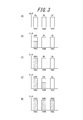
- FIG. 3 is a conceptual diagram illustrating output power distribution control according to the present embodiment.
- FIGS. 3A to 3E are graphs showing examples of output (%) of power supplied by the fuel cell units 100A, 100B, and 100C, respectively.
- FIG. 3A shows the time when the operation of the power supply system 1 starts. As shown in FIG. 3A, when the operation of the power supply system 1 is started, the fuel cell modules 7A, 7B, and 7C are in a standby state, and the electric power output from the fuel cell units 100A, 100B, and 100C is output. Each is 0%.
- the power supply device 200A master
- the power supply device 200A master
- the power supply device 200A master
- the power supply device 200A master
- the power supply device 200A master
- the output of the fuel cell module here 7B and 7C
- FIG. 3B shows that the output of the fuel cell module 7A is increased by such control, and the power supplied by the fuel cell unit 100A has reached 60% of the rating.
- the output of the other fuel cell modules here 7B and 7C
- FIG. 3C shows that the electric power supplied from the fuel cell unit 100A is rated (100%) by the control as described above.
- the power supply device 200A master
- the output is not increased (suppressed).
- FIG. 3D shows that the output of the fuel cell module 7B is increased by such control, and the power supplied by the fuel cell unit 100B reaches 60% of the rating.
- the output of the other fuel cell module (here 7C) that has not yet reached the rated output has not increased.
- FIG. 3E shows that the electric power supplied from the fuel cell unit 100B is rated (100%) by the control as described above.
- the power supply device 200A master
- FIG. 3 (E) shows that, by such control, the output of the fuel cell module 7C is increased and the power supplied by the fuel cell unit 100C is also rated (100%).
- FIG. 4 is a flowchart illustrating the above-described output power distribution control.
- FIG. 4 illustrates a process performed by the control unit 4A of the power supply device 200A (master) when the power supply system 1 operates based on the output power distribution control described above.
- the control unit 4A of the power supply device 200A instructs the power supply devices 200B and 200C (slave) to control to increase or decrease the output power of the fuel cell modules 7A, 7B, and 7C. .
- the control unit 4A of the power supply device 200A master
- the control unit 4A communicates with the control units 4B and 4C via the communication lines 120 and 140, so that various information including the output power of the fuel cell modules 7B and 7C of the fuel cell units 100B and 100C (slave), respectively. Can be acquired.
- the control unit 4A can also acquire various types of information including the output power of the fuel cell module 7A of the fuel cell unit 100A.
- the respective control units 4B and 4C are controlled to increase or decrease the outputs of the corresponding fuel cell modules 7B and 7C. To do. Further, the control unit 4A performs control so as to increase or decrease the output of the corresponding fuel cell module 7A.
- the power supply device 200A can acquire information such as the amount of power generated by the power supply devices 200B and 200C (slave).
- the power supply device 200A (master) can instruct the control units 4B and 4C about the amount of power generated by the power supply devices 200B and 200C (slave). Based on this instruction, the control units 4B and 4C of the power supply devices 200B and 200C can control the outputs of the respective fuel cell modules 7B and 7C.
- control unit 4A of the power supply device 200A determines whether or not the output power of the fuel cell module 7A connected to the power supply device 200A has reached the rating (step S11). ). When the output power of the fuel cell module 7A does not reach the rating in step S11, the control unit 4A increases the output power of the fuel cell module 7A connected to the power supply device 200A (step S12).
- the control unit 4A determines whether or not the output power of the fuel cell module 7B connected to the power supply device 200B has reached the rating (Ste S13).
- the control unit 4A performs control so as to increase the output power of the fuel cell module 7B connected to the power supply device 200B (step S14). Specifically, the control unit 4A instructs the control unit 4B to increase the power supplied from the power supply device 200B, and the control unit 4B increases the output power of the fuel cell module 7B.
- the control unit 4A determines whether or not the output power of the fuel cell module 7C connected to the power supply device 200C has reached the rating (Ste S15).
- the control unit 4A controls to increase the output power of the fuel cell module 7C connected to the power supply device 200C (step S16). Specifically, the control unit 4A instructs the control unit 4C to increase the power supplied by the power supply device 200C, and the control unit 4C increases the output power of the fuel cell module 7C.
- the aforementioned “predetermined time interval” is a relatively short time interval such as every 5 seconds. can do.
- the power supply device 200A controls the output power from the fuel cell module 7A that generates power using the combustion gas.
- the power supply device 200B controls the output power from the fuel cell module 7B that generates power using the combustion gas.
- the power supply device 200C controls the output power from the fuel cell module 7C that generates power using the combustion gas.
- the control unit 4A performs parallel operation with the other power supply devices 200B and 200C that supply output power from the other fuel cell modules 7B and 7C to the load 105.
- the following control is performed. That is, the control unit 4A has the rated output of the fuel cell modules other than the one fuel cell module until one of the fuel cell modules 7A, 7B, 7C (for example, 7A) reaches the rated output. The output power from the fuel cell modules that are not present (eg, 7B, 7C) is suppressed. In this case, the control unit 4A controls output power from the one fuel cell module (7A) while performing such control.
- control unit 4A maintains the output power of the one fuel cell module (7A) after one fuel cell module (for example, 7A) reaches the rated output. In this case, the control unit 4A performs such control and outputs power from another fuel cell module (for example, 7B) that is not rated output other than the one fuel cell module (7B, 7C). To control.
- a plurality of fuel cell modules may have the same rated output or different rated outputs.
- the output of only one fuel cell module is increased to the rated value, and other fuel cell modules that have not yet reached the rated output are suppressed to the idle state (output 0 kW).
- the output of only one fuel cell module increases to the rating
- the output of only one other fuel cell module that has not yet reached the rated output is increased to the rating. Therefore, in the present embodiment, since the plurality of fuel cell modules are controlled to increase their outputs to their respective ratings, the possibility that the combustion of each fuel cell module stops can be reduced.
- the output power change control described later is performed so that one fuel cell module does not become extremely low in temperature.
- control of the plurality of fuel cell modules is performed in the order of 7A, 7B, and 7C.
- control according to the present embodiment is not limited to such a mode.
- the control of the plurality of fuel cell modules can be performed based on a predetermined order according to various characteristics of the fuel cell, for example.
- the control of the plurality of fuel cell modules is based on the order dynamically determined by the control unit 4A of the master power supply device 200A according to the current status of each of the fuel cell modules 7A to 7C. You may go.
- control is performed so that the output power is alternately switched between the fuel cell module having a high output and the fuel cell module having a low output.
- control unit 4A of the power supply device 200A correlates the output power of each fuel cell module 7A, 7B, and 7C with the possibility that the combustion of the module stops. Get the data that prescribes. Such data can be acquired by the control unit 4A communicating with the control units 4B and 4C, respectively, and the acquired data can be stored in the memory 6 of the control unit 4A.
- the control unit 4A acquires and stores data on the threshold value of the output power at which the fuel cell modules 7A, 7B, and 7C are likely to stop combustion in each of the fuel cell modules 7A, 7B, and 7C. To do.
- the fuel cell module 7A, 7B, 7C has a high output and a low output.
- the output power is changed with the thing.
- FIG. 5 is a flowchart illustrating the above-described output power replacement control.
- the control unit 4A of the power supply device 200A increases the possibility that the combustion of the modules is stopped for each of the fuel cell modules 7A, 7B, and 7C.
- Data of a power threshold (hereinafter referred to as Px) is acquired.
- the output power threshold value Px may be a value common to the fuel cell modules 7A, 7B, and 7C, or may be a different value depending on various characteristics of the fuel cell modules 7A, 7B, and 7C.
- control unit 4A determines whether the outputs of the power supply devices 200A, 200B, and 200C, that is, the outputs of the fuel cell modules 7A, 7B, and 7C are less than the output power threshold value Px. Is determined (step S21).
- control unit 4A controls the control unit 4 connected to the fuel cell module 7 to count the predetermined time Ta (step S22).
- the control unit 4A controls the control unit 4 connected to the fuel cell module 7 to count the predetermined time Tb (step S23).
- the aforementioned “predetermined time Ta” is shorter than the predetermined time Tb, for example, 2 Set a relatively short time, such as minutes.
- the “predetermined time Tb” is longer than the predetermined time Ta, for example, 4 minutes Set a relatively long time.
- the predetermined times Ta and Tb may be values common to the fuel cell modules 7A, 7B, and 7C, or may be different values depending on various characteristics of the fuel cell modules 7A, 7B, and 7C.
- control unit 4A performs such a predetermined time Ta for each fuel cell module 7A, 7B, 7C according to the possibility that the combustion of each fuel cell module 7A, 7B, 7C stops. , Tb are determined in advance.
- control unit 4A When the predetermined time Ta or Tb is set in step S22 or step S23, the control unit 4A performs control so that each of the control units 4A to 4C counts the set time (step S24).
- the control unit 4A determines that the output of the power supply devices 200A, 200B, and 200C, that is, the output of the fuel cell modules 7A, 7B, and 7C, is the minimum output. The output power is changed so that Further, the control unit 4A alternates the output power so that the output of the power supply devices 200A, 200B, and 200C, that is, the output of the fuel cell modules 7A, 7B, and 7C becomes the maximum output (step). S25).
- predetermined time interval can be a relatively long time interval such as every three minutes.
- the control unit 4A includes the output power of the fuel cell module that outputs more than a predetermined threshold among the fuel cell modules 7A, 7B, and 7C, and the predetermined value.
- the output power of the fuel cell module that has not output more than the threshold value is switched at a predetermined timing.
- the operation of the high-power fuel cell module and the low-power fuel cell module is periodically switched. Therefore, in this embodiment, it is avoided that one fuel cell module is maintained at a low output for a long time. For this reason, in this embodiment, possibility that combustion of each fuel cell module will stop can be reduced.
- output power is replaced based on output power of a plurality of fuel cell modules, but the present embodiment is not limited to such a mode.
- the threshold value of the output electric power in step S21 may be set, or predetermined time Ta or Tb in step S22 or step S23 may be set.
- step S25 the output power is changed between the maximum output fuel cell module and the minimum output fuel cell module.
- output power may be switched between a group of fuel cell modules that output at a predetermined level or more and a group of fuel cell modules that output at a predetermined level or lower.
- the output power is switched between the fuel cell module that suppresses output in this way and the low-power fuel cell module. Also good.
- each functional unit, each means, each step, etc. can be rearranged so that there is no logical contradiction, and a plurality of functional units, steps, etc. are combined or divided into one. It is possible.
- each of the embodiments of the present invention described above is not limited to being performed faithfully to each of the embodiments described above, and is implemented by appropriately combining the features or omitting some of the features. You can also.
- the present invention can be implemented not only as an invention of the power supply device 200A but also as an invention of a power supply system including a plurality of power supply devices such as the power supply devices 200A to 200C.
- one of the plurality of power supply devices includes the control unit 4A.
- the control unit 4A performs parallel operation with other power supply devices (200B, 200C) among the plurality of power supply devices, one of the plurality of fuel cell modules 7A, 7B, 7C is set to the rated output. Until then, the output power from the one fuel cell module is controlled while suppressing the output power from the fuel cell module other than the one fuel cell module that is not rated output.
- the present invention can also be implemented as a power supply method in the power supply system as described above.
- the method includes the step of performing the parallel operation of the plurality of power supply devices 200A, 200B, and 200C, and one of the plurality of fuel cell modules 7A, 7B, and 7C until the rated output is achieved. Controlling output power from the one fuel cell module while suppressing output power from the fuel cell module that is not rated output among fuel cell modules other than the fuel cell module.
- the computer system and other hardware include, for example, a general-purpose computer, a PC (personal computer), a dedicated computer, a workstation, a PCS (Personal Communications System, a personal mobile communication system), an electronic note pad, a laptop computer, or other program Possible data processing devices are included.
- the various operations are performed by dedicated circuitry (e.g., individual logic gates interconnected to perform specific functions) or one or more processors implemented with program instructions (software). Note that the program is executed by a logical block or a program module.
- processors that execute logic blocks or program modules include, for example, one or more microprocessors, CPU (central processing unit), ASIC (Application Specific Integrated Circuit), DSP (Digital Signal Processor), PLD (Programmable Logic Device), FPGA (Field Programmable Gate Array), controller, microcontroller, electronic device, other devices designed to perform the functions described herein, and / or any combination thereof.
- CPU central processing unit
- ASIC Application Specific Integrated Circuit
- DSP Digital Signal Processor
- PLD Programmable Logic Device
- FPGA Field Programmable Gate Array
- controller microcontroller
- electronic device other devices designed to perform the functions described herein, and / or any combination thereof.
- the illustrated embodiments are implemented, for example, by hardware, software, firmware, middleware, microcode, or any combination thereof.
- the machine-readable non-transitory storage medium used here can be further configured as a computer-readable tangible carrier (medium) composed of solid state memory, magnetic disk and optical disk.
- a medium stores an appropriate set of computer instructions such as program modules for causing a processor to execute the technology disclosed herein, and a data structure.
- Computer readable media include electrical connections with one or more wires, magnetic disk storage media, and other magnetic and optical storage devices (eg, CD (Compact Disk), DVD (registered trademark) (Digital Versatile Disk) ), Blu-ray Disc (registered trademark)), portable computer disc, RAM (Random Access Memory), ROM (Read-Only Memory), EPROM, EEPROM, flash memory, etc. Possible other tangible storage media or any combination thereof are included.
- the memory can be provided inside and / or outside the processor / processing unit.
- the term “memory” means any type of long-term storage, short-term storage, volatile, non-volatile, or other memory in which a particular type or number of memories or storage is stored. The type of medium is not limited.
Abstract
Description
燃焼ガスを用いて発電を行う所定の燃料電池モジュールからの出力電力を制御する電力供給機器であって、
他の燃料電池モジュールからの出力電力を負荷に供給する他の電力供給機器と並列運転を行う際に、前記所定の燃料電池モジュールおよび前記他の燃料電池モジュールのうちの1つが定格出力になるまでは、前記1つの燃料電池モジュール以外の燃料電池モジュールのうち定格出力になっていない燃料電池モジュールからの出力電力を抑制しつつ、前記1つの燃料電池モジュールからの出力電力を制御する制御部を備える。 The invention according to the first aspect to achieve the above object is
A power supply device that controls output power from a predetermined fuel cell module that generates power using combustion gas,
When one of the predetermined fuel cell module and the other fuel cell module reaches a rated output when performing parallel operation with another power supply device that supplies output power from another fuel cell module to a load. Includes a control unit that controls output power from the one fuel cell module while suppressing output power from a fuel cell module that is not rated output among fuel cell modules other than the one fuel cell module. .
燃焼ガスを用いて発電を行なう複数の燃料電池モジュールと、
前記複数の燃料電池モジュールの各々からの出力電力を負荷に供給する複数の電力供給機器と、
を含む電力供給システムであって、
前記複数の電力供給機器のうちの1つは、前記複数の電力供給機器のうち他の電力供給機器と並列運転を行う際に、前記複数の燃料電池モジュールのうちの1つが定格出力になるまでは、前記1つの燃料電池モジュール以外の燃料電池モジュールのうち定格出力になっていない燃料電池モジュールからの出力電力を抑制しつつ、前記1つの燃料電池モジュールからの出力電力を制御する制御部を備える。 The invention according to the second aspect is
A plurality of fuel cell modules that generate power using combustion gas;
A plurality of power supply devices for supplying output power from each of the plurality of fuel cell modules to a load;
A power supply system comprising:
When one of the plurality of power supply devices performs parallel operation with another power supply device among the plurality of power supply devices, until one of the plurality of fuel cell modules reaches a rated output. Includes a control unit that controls output power from the one fuel cell module while suppressing output power from a fuel cell module that is not rated output among fuel cell modules other than the one fuel cell module. .
燃焼ガスを用いて発電を行なう複数の燃料電池モジュールと、
前記複数の燃料電池モジュールの各々からの出力電力を負荷に供給する複数の電力供給機器と、
を含む電力供給システムにおける電力供給方法であって、
前記複数の電力供給機器の並列運転を行うステップと、
前記複数の燃料電池モジュールのうちの1つが定格出力になるまでは、前記1つの燃料電池モジュール以外の燃料電池モジュールのうち定格出力になっていない燃料電池モジュールからの出力電力を抑制しつつ、前記1つの燃料電池モジュールからの出力電力を制御するステップと、
を含む。 The invention according to the third aspect is
A plurality of fuel cell modules that generate power using combustion gas;
A plurality of power supply devices for supplying output power from each of the plurality of fuel cell modules to a load;
A power supply method in a power supply system including:
Performing parallel operation of the plurality of power supply devices;
Until one of the plurality of fuel cell modules has a rated output, while suppressing output power from a fuel cell module that is not rated output among fuel cell modules other than the one fuel cell module, Controlling the output power from one fuel cell module;
including.
本実施形態では、複数の燃料電池モジュール7A,7B,7Cのうち、低出力になる燃料電池モジュールを極力発生させないようにする。このため、本実施形態では、全ての燃料電池モジュールの出力を均等化せずに、まず1つの燃料電池モジュールのみの出力を増大させ、当該1つが定格出力になったら2つ目の出力を増大する、というような制御を行う。ここで、出力を増大しない燃料電池モジュールのうち定格出力になっていないものは、その出力を抑制するように制御する。 (1) Output power distribution control In the present embodiment, among the plurality of
次に、本実施形態に係る電力供給システム1における出力電力の交替制御を説明する。 (2) Output Power Replacement Control Next, output power replacement control in the power supply system 1 according to the present embodiment will be described.
1a,1b ガス電磁弁
2 ガス流量計
3 ガスポンプ
4A,4B,4C 制御部
5 マイコン
6 メモリ
7A,7B,7C 燃料電池モジュール
8 セルスタック
9 ヒータ
10A,10B,10C パワーコンディショナ(インバータ)
11 DC/DCコンバータ
12 インバータ
13a,13b,13c スイッチ
14 凍結防止ヒータ
100A,100B,100C 燃料電池ユニット
101 ガスメータ
104 系統
105 負荷
110A,110B,110C 電流センサ
120,140 通信線
200A,200B,200C 電力供給機器 DESCRIPTION OF SYMBOLS 1 Electric
11 DC /
Claims (9)
- 燃焼ガスを用いて発電を行う所定の燃料電池モジュールからの出力電力を制御する電力供給機器であって、
他の燃料電池モジュールからの出力電力を負荷に供給する他の電力供給機器と並列運転を行う際に、前記所定の燃料電池モジュールおよび前記他の燃料電池モジュールのうちの1つの燃料電池モジュールが定格出力になるまでは、前記1つの燃料電池モジュール以外の燃料電池モジュールのうち定格出力になっていない燃料電池モジュールからの出力電力を抑制しつつ、前記1つの燃料電池モジュールからの出力電力を制御する制御部を備える電力供給機器。 A power supply device that controls output power from a predetermined fuel cell module that generates power using combustion gas,
When performing parallel operation with another power supply device that supplies output power from another fuel cell module to a load, one of the predetermined fuel cell modules and the other fuel cell module is rated. Until the output is reached, the output power from the one fuel cell module is controlled while suppressing the output power from the fuel cell module that is not the rated output among the fuel cell modules other than the one fuel cell module. A power supply device including a control unit. - 前記制御部は、前記1つの燃料電池モジュールが定格出力になった後は、前記1つの燃料電池モジュールの出力電力を維持しつつ、前記1つの燃料電池モジュール以外の定格出力になっていない他の1つの燃料電池モジュールからの出力電力の制御をする、請求項1に記載の電力供給機器。 After the one fuel cell module has reached the rated output, the control unit maintains the output power of the one fuel cell module, and other than the rated output other than the one fuel cell module. The power supply device according to claim 1, wherein output power from one fuel cell module is controlled.
- 前記制御部は、前記所定の燃料電池モジュールおよび前記他の燃料電池モジュールのうち、所定の閾値以上出力している燃料電池モジュールの出力電力と、所定の閾値以上出力していない燃料電池モジュールの出力電力とを、所定のタイミングで切替える、請求項1または2に記載の電力供給機器。 The control unit includes: an output power of a fuel cell module that outputs a predetermined threshold value or more, and an output of a fuel cell module that does not output a predetermined threshold value or more, among the predetermined fuel cell module and the other fuel cell modules. The power supply device according to claim 1 or 2, wherein the power is switched at a predetermined timing.
- 燃焼ガスを用いて発電を行なう複数の燃料電池モジュールと、
前記複数の燃料電池モジュールの各々からの出力電力を負荷に供給する複数の電力供給機器と、
を含む電力供給システムであって、
前記複数の電力供給機器のうちの1つは、前記複数の電力供給機器のうち他の電力供給機器と並列運転を行う際に、前記複数の燃料電池モジュールのうちの1つの燃料電池モジュールが定格出力になるまでは、前記1つの燃料電池モジュール以外の燃料電池モジュールのうち定格出力になっていない燃料電池モジュールからの出力電力を抑制しつつ、前記1つの燃料電池モジュールからの出力電力を制御する制御部を備える、電力供給システム。 A plurality of fuel cell modules that generate power using combustion gas;
A plurality of power supply devices for supplying output power from each of the plurality of fuel cell modules to a load;
A power supply system comprising:
When one of the plurality of power supply devices performs parallel operation with another power supply device among the plurality of power supply devices, one fuel cell module of the plurality of fuel cell modules is rated. Until the output is reached, the output power from the one fuel cell module is controlled while suppressing the output power from the fuel cell module that is not the rated output among the fuel cell modules other than the one fuel cell module. A power supply system including a control unit. - 前記制御部は、前記1つの燃料電池モジュールが定格出力になった後は、前記1つの燃料電池モジュールの出力電力を維持しつつ、前記1つの燃料電池モジュール以外の定格出力になっていない他の1つの燃料電池モジュールからの出力電力の制御をする、請求項4に記載の電力供給システム。 After the one fuel cell module has reached the rated output, the control unit maintains the output power of the one fuel cell module, and other than the rated output other than the one fuel cell module. The power supply system according to claim 4, wherein output power from one fuel cell module is controlled.
- 前記制御部は、前記複数の燃料電池モジュールのうち、所定の閾値以上出力している燃料電池モジュールの出力電力と、所定の閾値以上出力していない燃料電池モジュールの出力電力とを、所定のタイミングで切替える、請求項4または5に記載の電力供給システム。 The control unit outputs an output power of a fuel cell module that outputs more than a predetermined threshold among the plurality of fuel cell modules and an output power of a fuel cell module that does not output more than a predetermined threshold at a predetermined timing. The power supply system according to claim 4 or 5, wherein switching is performed at
- 燃焼ガスを用いて発電を行なう複数の燃料電池モジュールと、
前記複数の燃料電池モジュールの各々からの出力電力を負荷に供給する複数の電力供給機器と、
を含む電力供給システムにおける電力供給方法であって、
前記複数の電力供給機器の並列運転を行うステップと、
前記複数の燃料電池モジュールのうちの1つの燃料電池モジュールが定格出力になるまでは、前記1つの燃料電池モジュール以外の燃料電池モジュールのうち定格出力になっていない燃料電池モジュールからの出力電力を抑制しつつ、前記1つの燃料電池モジュールからの出力電力を制御するステップと、
を含む、電力供給方法。 A plurality of fuel cell modules that generate power using combustion gas;
A plurality of power supply devices for supplying output power from each of the plurality of fuel cell modules to a load;
A power supply method in a power supply system including:
Performing parallel operation of the plurality of power supply devices;
Until one fuel cell module of the plurality of fuel cell modules reaches a rated output, output power from a fuel cell module other than the one fuel cell module that is not rated output is suppressed. While controlling the output power from the one fuel cell module;
A power supply method. - 前記制御するステップにおいて、前記1つの燃料電池モジュールが定格出力になった後は、前記1つの燃料電池モジュールの出力電力を維持しつつ、前記1つの燃料電池モジュール以外の定格出力になっていない他の1つの燃料電池モジュールからの出力電力の制御をする、請求項7に記載の電力供給方法。 In the controlling step, after the one fuel cell module has reached the rated output, the output power of the one fuel cell module is maintained and the rated output other than the one fuel cell module has not been achieved. The power supply method according to claim 7, wherein output power from one of the fuel cell modules is controlled.
- 前記制御するステップにおいて、前記複数の燃料電池モジュールのうち、所定の閾値以上出力している燃料電池モジュールの出力電力と、所定の閾値以上出力していない燃料電池モジュールの出力電力とを、所定のタイミングで切替える、請求項7または8に記載の電力供給方法。 In the controlling step, an output power of a fuel cell module that outputs a predetermined threshold value or more of the plurality of fuel cell modules and an output power of a fuel cell module that does not output a predetermined threshold value or more are set to a predetermined value. The power supply method according to claim 7 or 8, wherein switching is performed at timing.
Priority Applications (3)
| Application Number | Priority Date | Filing Date | Title |
|---|---|---|---|
| US15/513,893 US20170294663A1 (en) | 2014-09-26 | 2015-09-25 | Power supply apparatus, power supply system, and power supply method |
| EP15844600.5A EP3200307A4 (en) | 2014-09-26 | 2015-09-25 | Power supply device, power supply system, and power supply method |
| JP2016549960A JPWO2016047146A1 (en) | 2014-09-26 | 2015-09-25 | Power supply device, power supply system, and power supply method |
Applications Claiming Priority (2)
| Application Number | Priority Date | Filing Date | Title |
|---|---|---|---|
| JP2014-196928 | 2014-09-26 | ||
| JP2014196928 | 2014-09-26 |
Publications (1)
| Publication Number | Publication Date |
|---|---|
| WO2016047146A1 true WO2016047146A1 (en) | 2016-03-31 |
Family
ID=55580692
Family Applications (1)
| Application Number | Title | Priority Date | Filing Date |
|---|---|---|---|
| PCT/JP2015/004875 WO2016047146A1 (en) | 2014-09-26 | 2015-09-25 | Power supply device, power supply system, and power supply method |
Country Status (4)
| Country | Link |
|---|---|
| US (1) | US20170294663A1 (en) |
| EP (1) | EP3200307A4 (en) |
| JP (1) | JPWO2016047146A1 (en) |
| WO (1) | WO2016047146A1 (en) |
Cited By (6)
| Publication number | Priority date | Publication date | Assignee | Title |
|---|---|---|---|---|
| CN105870976A (en) * | 2016-04-15 | 2016-08-17 | 国家电网公司 | Energy environment efficiency-based low-carbon dispatching method and device |
| JP2018007335A (en) * | 2016-06-28 | 2018-01-11 | 京セラ株式会社 | Power generating system and control method therefor |
| JP2018139082A (en) * | 2017-02-24 | 2018-09-06 | 京セラ株式会社 | Power supply system and power supply system control method |
| JP2018185085A (en) * | 2017-04-25 | 2018-11-22 | 大阪瓦斯株式会社 | Energy supply system |
| JP2019153519A (en) * | 2018-03-06 | 2019-09-12 | トヨタ自動車株式会社 | Fuel cell system |
| US10930958B2 (en) | 2018-08-24 | 2021-02-23 | Toyota Jidosha Kabushiki Kaisha | Fuel cell system |
Families Citing this family (4)
| Publication number | Priority date | Publication date | Assignee | Title |
|---|---|---|---|---|
| CN108215894B (en) * | 2017-12-28 | 2021-09-03 | 同济大学 | Composite fuel cell power supply system and control method |
| CN113364114A (en) * | 2020-03-04 | 2021-09-07 | 台达电子工业股份有限公司 | Smart power grid system and power management method thereof |
| JP7400749B2 (en) * | 2021-01-29 | 2023-12-19 | トヨタ自動車株式会社 | fuel cell system |
| AT526315A1 (en) * | 2022-10-31 | 2023-12-15 | Avl List Gmbh | Fuel cell supply system |
Citations (2)
| Publication number | Priority date | Publication date | Assignee | Title |
|---|---|---|---|---|
| JP2004327160A (en) * | 2003-04-23 | 2004-11-18 | Aisin Seiki Co Ltd | Fuel cell cogeneration system |
| JP2009043520A (en) * | 2007-08-08 | 2009-02-26 | Panasonic Corp | Power supply system |
Family Cites Families (2)
| Publication number | Priority date | Publication date | Assignee | Title |
|---|---|---|---|---|
| JP2007122930A (en) * | 2005-10-25 | 2007-05-17 | Kawamura Electric Inc | Fuel cell unit |
| JP2011175963A (en) * | 2010-01-29 | 2011-09-08 | Sanyo Electric Co Ltd | Fuel cell system |
-
2015
- 2015-09-25 WO PCT/JP2015/004875 patent/WO2016047146A1/en active Application Filing
- 2015-09-25 EP EP15844600.5A patent/EP3200307A4/en not_active Withdrawn
- 2015-09-25 US US15/513,893 patent/US20170294663A1/en not_active Abandoned
- 2015-09-25 JP JP2016549960A patent/JPWO2016047146A1/en active Pending
Patent Citations (2)
| Publication number | Priority date | Publication date | Assignee | Title |
|---|---|---|---|---|
| JP2004327160A (en) * | 2003-04-23 | 2004-11-18 | Aisin Seiki Co Ltd | Fuel cell cogeneration system |
| JP2009043520A (en) * | 2007-08-08 | 2009-02-26 | Panasonic Corp | Power supply system |
Non-Patent Citations (1)
| Title |
|---|
| See also references of EP3200307A4 * |
Cited By (7)
| Publication number | Priority date | Publication date | Assignee | Title |
|---|---|---|---|---|
| CN105870976A (en) * | 2016-04-15 | 2016-08-17 | 国家电网公司 | Energy environment efficiency-based low-carbon dispatching method and device |
| JP2018007335A (en) * | 2016-06-28 | 2018-01-11 | 京セラ株式会社 | Power generating system and control method therefor |
| JP2018139082A (en) * | 2017-02-24 | 2018-09-06 | 京セラ株式会社 | Power supply system and power supply system control method |
| JP2018185085A (en) * | 2017-04-25 | 2018-11-22 | 大阪瓦斯株式会社 | Energy supply system |
| JP2019153519A (en) * | 2018-03-06 | 2019-09-12 | トヨタ自動車株式会社 | Fuel cell system |
| JP7420464B2 (en) | 2018-03-06 | 2024-01-23 | トヨタ自動車株式会社 | fuel cell system |
| US10930958B2 (en) | 2018-08-24 | 2021-02-23 | Toyota Jidosha Kabushiki Kaisha | Fuel cell system |
Also Published As
| Publication number | Publication date |
|---|---|
| EP3200307A4 (en) | 2018-04-25 |
| JPWO2016047146A1 (en) | 2017-04-27 |
| US20170294663A1 (en) | 2017-10-12 |
| EP3200307A1 (en) | 2017-08-02 |
Similar Documents
| Publication | Publication Date | Title |
|---|---|---|
| WO2016047146A1 (en) | Power supply device, power supply system, and power supply method | |
| US20210367425A1 (en) | Grid-tied variable frequency facility | |
| JP2017199413A (en) | Power conversion device, method for controlling power conversion device and power conversion system | |
| US10541437B2 (en) | Fuel cell system, control method of fuel cell system, and fuel cell control apparatus | |
| US10566796B2 (en) | Control method of power generation system, power generation system, and power generation apparatus | |
| JP6205077B2 (en) | Power supply device, power supply system, and power supply method | |
| WO2015015794A1 (en) | Power-supply-device identification apparatus, power-supply-device identification method, and power conversion apparatus | |
| JP6294494B2 (en) | Power supply device, power supply system, and power supply method | |
| JP2016019430A (en) | Power generation system control method, power generation system, and power generator | |
| US10523015B2 (en) | Power generation apparatus, power generation system, and power generation method | |
| JP6475945B2 (en) | Power supply device, power supply method, and power supply system | |
| JP6216066B2 (en) | Power control system control method, power control system, and power control apparatus | |
| JP6235139B2 (en) | CONTROL METHOD FOR FUEL CELL SYSTEM, FUEL CELL SYSTEM, AND POWER CONTROL DEVICE | |
| WO2016121389A1 (en) | Electrical power supply device, electrical power supply system, and electrical power supply method | |
| JP6659736B2 (en) | Power generation system, power generation system control method, and power generation device | |
| JP6452330B2 (en) | Power generation device, power generation system, and power generation method | |
| JP2011049053A (en) | Power generation system | |
| JP2016019428A (en) | Power generator, power generation system, and power generation method | |
| JP2009043529A (en) | Device for generating fuel cell power |
Legal Events
| Date | Code | Title | Description |
|---|---|---|---|
| 121 | Ep: the epo has been informed by wipo that ep was designated in this application |
Ref document number: 15844600 Country of ref document: EP Kind code of ref document: A1 |
|
| ENP | Entry into the national phase |
Ref document number: 2016549960 Country of ref document: JP Kind code of ref document: A |
|
| REEP | Request for entry into the european phase |
Ref document number: 2015844600 Country of ref document: EP |
|
| WWE | Wipo information: entry into national phase |
Ref document number: 2015844600 Country of ref document: EP |
|
| NENP | Non-entry into the national phase |
Ref country code: DE |
|
| WWE | Wipo information: entry into national phase |
Ref document number: 15513893 Country of ref document: US |