EP3876372A1 - Explosionsgeschützte vorrichtung - Google Patents
Explosionsgeschützte vorrichtung Download PDFInfo
- Publication number
- EP3876372A1 EP3876372A1 EP21160184.4A EP21160184A EP3876372A1 EP 3876372 A1 EP3876372 A1 EP 3876372A1 EP 21160184 A EP21160184 A EP 21160184A EP 3876372 A1 EP3876372 A1 EP 3876372A1
- Authority
- EP
- European Patent Office
- Prior art keywords
- inner body
- explosion
- housing
- section
- proof device
- Prior art date
- Legal status (The legal status is an assumption and is not a legal conclusion. Google has not performed a legal analysis and makes no representation as to the accuracy of the status listed.)
- Granted
Links
Images



Classifications
-
- H—ELECTRICITY
- H02—GENERATION; CONVERSION OR DISTRIBUTION OF ELECTRIC POWER
- H02G—INSTALLATION OF ELECTRIC CABLES OR LINES, OR OF COMBINED OPTICAL AND ELECTRIC CABLES OR LINES
- H02G3/00—Installations of electric cables or lines or protective tubing therefor in or on buildings, equivalent structures or vehicles
- H02G3/22—Installations of cables or lines through walls, floors or ceilings, e.g. into buildings
-
- H—ELECTRICITY
- H02—GENERATION; CONVERSION OR DISTRIBUTION OF ELECTRIC POWER
- H02G—INSTALLATION OF ELECTRIC CABLES OR LINES, OR OF COMBINED OPTICAL AND ELECTRIC CABLES OR LINES
- H02G3/00—Installations of electric cables or lines or protective tubing therefor in or on buildings, equivalent structures or vehicles
- H02G3/02—Details
- H02G3/04—Protective tubing or conduits, e.g. cable ladders or cable troughs
- H02G3/0406—Details thereof
-
- H—ELECTRICITY
- H02—GENERATION; CONVERSION OR DISTRIBUTION OF ELECTRIC POWER
- H02G—INSTALLATION OF ELECTRIC CABLES OR LINES, OR OF COMBINED OPTICAL AND ELECTRIC CABLES OR LINES
- H02G15/00—Cable fittings
- H02G15/02—Cable terminations
- H02G15/04—Cable-end sealings
Definitions
- the invention relates to an explosion-proof device according to the preamble of claim 1.
- a conduit fitting arrangement for a connection between a wall and a conduit which comprises a seal.
- the seal consists of a ring with a rectangular cross-section and a V-shaped groove that runs around the outer edge of the ring.
- the arrangement comprises a deformable inner body, which has at least one line channel extending in a longitudinal direction through the inner body, with at least one line extending through the at least one line channel and having at least one electrical and / or optical conductor, the inner body is enclosed by a connecting sleeve in a circumferential direction around the longitudinal direction, which consists of a plastically deformable material and presses inwardly on the inner body by plastic deformation of a connecting section, deforms the inner body and thereby connects positively to the line, the plastically deformed connecting section having a, has a section outer surface which is plastically deformed to form a second delimiting surface and which, together with a lead-through surface formed by the first delimiting surface, forms a flameproof explosion-proof gap.
- EP 0 598 136 A1 a sealing structure for a hole in a metallic wall part designed to pass through a part, in which a part, which is provided for connecting a device arranged on one side of the wall part to a device arranged on the opposite side of the wall part, is drilled into the metallic wall part Hole is passed through, wherein the connecting part is resistant to radial compression and its axial length is greater than the thickness of the metallic wall part, and in which a sealing part is provided for sealing the hole.
- the sealing part is arranged between the lead-through part and the inner wall surface of the hole, the sealing part having an outer diameter which is substantially equal to the inner diameter of the hole and an axial length which is equal to or greater than the thickness of the metallic wall part.
- a constriction region is formed in at least one of the openings at the opposite ends of the hole.
- the lead-through part and the sealing part are compressed from their peripheral areas by means of the constriction area, the sealing part being clamped in the hole in order to thereby seal the hole.
- a device for dust ignition-safe passage of a component through an opening in a wall of an explosion-proof housing is known.
- a deformable and / or malleable sealing element is placed directly in the opening in the wall.
- a clamping arrangement serves to clamp the sealing element against a clamping section of the wall, the clamping section tapering transversely to a feed-through direction.
- the clamping arrangement exerts an axial clamping force on the sealing element in the feed-through direction.
- the sealing element can deform at least slightly in the radial direction and comes to rest against the opening in the wall and against the component that is guided through the sealing element. This leads to a dust ignition-proof arrangement.
- the object of the present invention is therefore to provide an explosion-proof device in which explosion protection is guaranteed even at low temperatures or in the event of strong temperature fluctuations.
- the invention thus relates to an explosion-proof device comprising a deformable inner body which has at least one conduit that extends through the inner body along a longitudinal axis.
- a line runs through this at least one line channel.
- the line can be an optical or electrical line.
- the inner body is enclosed by a housing in a circumferential direction along the longitudinal axis, the housing having an input section for the at least one line, an output section for the at least one line and a middle section located therebetween.
- the middle section is at least partially outside an explosion-proof area and the exit section is in the explosion-proof area.
- the explosion-proof device also has a spring element which is arranged in the middle section and constantly exerts pressure on the inner body. The pressure generated by the spring force is great enough to deform the inner body.
- the spring element thus ensures that the inner body rests completely against the inner wall of the housing surrounding it and the at least one line even at very low temperatures or in the event of strong temperature fluctuations.
- first support disk with at least one passage for a line and extending along the longitudinal axis of the housing
- second support disk is provided with at least one passage for a line extending along the longitudinal axis, these two support disks surrounding the inner body along a transverse axis.
- the first support disk is arranged in the outlet section and the second support disk is arranged in the middle section of the housing.
- These two support disks are not attached to the housing, so that the two support disks are arranged within the housing so that they can be moved along the longitudinal axis.
- the pretensioned spring element constantly exerts pressure on the second support disc and thus also on the inner body and the first support disc, so that the spring element presses the two support discs and the inner body in the direction of the output section.
- the pressure is so great that it is able to deform the inner body. This ensures that in the event of undesired deformations of the inner body - especially at low temperatures or with strong temperature fluctuations - the spring element presses the second support disc further onto the inner body, whereby the inner body continues to remain in full contact with the housing or with the support discs and thus a Fills the interior space between the two support disks completely and also surrounds the lines. It goes without saying that the spring force that is required for this depends on the material of the inner body. A person skilled in the art will therefore use such a spring element for a specific material of the inner body which is capable of exerting sufficient pressure on the inner body in order to deform the inner body.
- the at least one passage of the second support disc and the at least one passage of the first support disc as well as the at least one duct of the inner body form a duct through which the one duct is passed.
- several feedthroughs are provided in the two support disks and several line ducts are provided in the inner body, which ducts are arranged with respect to one another in such a way that a plurality of ducts are formed for one line each. It goes without saying that the number of conduits and the number of passages through the two support disks are identical in this case.
- a mounting screw is provided for pretensioning the spring element, which is introduced in the input section of the housing. With this mounting screw, the spring force of the spring element can be easily adjusted by tightening or loosening the mounting screw.
- an adapter sleeve movable along the longitudinal axis is arranged between the second support disk and the spring element.
- This adapter sleeve is used to transmit the force of the spring force of the spring element to the second support disk.
- This adapter sleeve is particularly suitable as an anti-twist device. Without such an adapter sleeve, the rotational movement of the assembly screw would be transmitted to the first support disk and the first support disk would rotate relative to the inner body, which could lead to the lines being sheared off.
- a sleeve which surrounds the inner body along the longitudinal axis and the two support disks, the sleeve being arranged between the inner body and the housing.
- the inner body consists of at least two sections. But it is also possible that the inner body consists of granules or powder.
- the assembly of the lines is made easier.
- FIG. 1 a perspective view of an explosion-protected device 1 is shown, which can be arranged at least partially in an explosion-protected area 7.
- the device 1 comprises a housing 2, having an inlet section 3 and an outlet section 4 as well as a middle section 5 located in between.
- the middle section 5 has a taper 6 on the outside.
- a sealing ring can be inserted into this taper 6, a sealing ring not being shown.
- a wall that separates the explosion-proof area 7 from an explosion-endangered area 8 bears the reference number 42.
- the exit section 4 is located completely in the explosion-proof area 7, whereas the middle section 5 is only partially arranged in the explosion-proof area 7.
- Several lines are provided, which are introduced into the housing 2 via the input section 3 and lead out again via the output section 4.
- the lines 9 to 12 can be optical or electrical lines.
- the lines 9 to 12 are guided through the housing 2 along a longitudinal axis L.
- the electrical lines can carry electricity into the explosion-protected area.
- the optical Lines can be fiber optic lines with which optical measurements can be carried out in the explosion-protected area or optical lines that are connected to a sensor that are located in the explosion-protected area (not shown).
- the lines can also be used for data transmission. It goes without saying that the lines are insulated by a protective layer made of plastic, the plastic layer not being shown separately, especially since such lines are commercially available.
- a mounting screw 13 is introduced into the input section 3, with which a spring element (not shown) located in the housing 2 can be pretensioned.
- the mounting screw 13 has a passage for lines along the longitudinal axis L, so that the lines 9 to 12 can be passed through the mounting screw 13.
- the mounting screw 13 can also be dispensed with if the spring force is applied to the spring element in a different manner. For example, it is possible to introduce the spring element into the housing 2 in a pretensioned manner and then to apply a cap which closes the housing 2 and by means of which the spring element remains pretensioned. It goes without saying that the cap also has bushings for lines.
- the housing 2 and the mounting screw 13 are preferably made of a metal, a metal alloy or a highly reinforced plastic.
- the housing 2 or the mounting screw 13 can consist of stainless steel or polyetheretherketone (PEEK).
- PEEK polyetheretherketone
- two grooves 39, 40 are provided, into each of which a locking ring can be introduced in order to hold the device 1 in the wall 42.
- Retaining rings are in the Figure 1 Not shown. It is important that a securing ring for holding the device 1 in the wall 42 is provided at least in the groove 39. A securing ring in the groove 40 can therefore also be dispensed with.
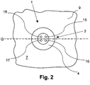
- FIG. 3 is a further view of the explosion-proof device 1 according to FIG Figure 1 is shown, looking at the exit section 4 (Viewing direction A).
- the output section 4 of the housing 2 of the device 1 is thus located in the explosion-proof area 7, which is separated from the potentially explosive area by the wall 42, so that this potentially explosive area cannot be seen.
- the wall 42 is in the Figure 2 shown only in part.
- a first support disk 14 is provided which has four passages 15 to 18 through which the lines 9 to 12 (cf. Figure 1 ) are passed through and leave the output section 4 of the housing 2. So that the bushings 15 to 18 can be seen better, the lines are in the Figure 2 not shown.
- This first support disk 14 is arranged in the housing 2 along a transverse axis Q.
- Figure 3 shows a longitudinal section through the explosion-proof device 1 according to Figure 1 so that an inner region 19 of the housing 2 can be seen.
- a deformable inner body 20 adjoins the support disk 14 arranged in the outlet section 4 and a second support disk 21 adjoins it, so that the inner body 20 is surrounded by the two support disks 14, 21.
- the inner body 20 and the second support disk 21 are arranged in the central section 5 of the housing 2.
- a sleeve 23 is arranged between the inner region 19 of the housing 2 and an arrangement 22 comprising the two support disks 14, 21 and the inner body 20.
- the use of a sleeve 23 means that an additional component must be used.
- the sleeve 23 can therefore also be dispensed with, as a result of which the arrangement 22 would be in direct contact with the housing 2.
- Two passages 15, 16 of the first support disk 14 and two passages 32, 33 of the second support disk 21 as well as two conduits 30, 31 of the inner body 20 can be seen through the longitudinal section L.
- the bushings 16, 33 and the conduit 31 form one Feed-through channel 34 and the feed-throughs 15, 32 and the line channel 30 have a feed-through channel 35.
- the lines 9, 11 have not been shown so that the feed-through channels 34, 35 can be seen.
- the lines 10 and 12 are guided through two further ducts (not visible) of the inner body 20.
- a soft plastic is suitable as the material for the sleeve 23.
- the two support disks 14, 21 can be made of plastic, metal or a metal alloy.
- the inner body 20 consists of a plastically easily deformable material, for example graphite or plastic.
- the middle section 5 has a taper 6 in an outer region, in which a sealing element (not shown) can be arranged in order to seal a gap between wall 42 and housing 2 in accordance with the desired IP class.
- the wall 42 shown only schematically, separates the explosion-proof area 7 from the explosion-endangered area 8.
- the exit section 4 is located completely in the explosion-proof area 7, whereas the middle section 5 is only partially arranged in the explosion-proof area 7.
- a movable adapter sleeve 24 is provided, which is arranged between the second support disk 21 and the spring element 25.
- the mounting screw 13, with which the spring element 25 can be pretensioned, is introduced into the input section 3 of the housing 2.
- the mounting screw 13, like the spring element 25 and the adapter sleeve 24, has a central passage 26, 27 and 28 for lines along the longitudinal axis L so that the lines can be passed through the mounting screw 13, spring element 25 and the adapter sleeve 24.
- Figure 4 only the two lines 10 and 12 are shown. It is also conceivable to pass the lines laterally through feedthroughs in the area of the adapter sleeve 24 (not shown). In this case spring elements and mounting screws could also be used without a central leadthrough.
- the adapter sleeve 24 serves to transmit the force of the spring force of the spring element 25 to the second support disk 21 and to prevent rotation.
- the adapter sleeve 24 is arranged to be movable along the longitudinal axis L for this purpose. Since the second support disk 21 and the adapter sleeve 24 are movably arranged in the sleeve 23 along the longitudinal axis L, the adapter sleeve 24 is pushed onto the second support disk 21 by the spring force of the spring element 25, the support disk 21 in turn exerting the force on the deformable inner body 20 transmits.
- the spring element 25 and the second support disk 21 continue to press on the inner body 20, whereby the inner body 20 continues to be completely connected to the sleeve 23 or with the Support disks 14, 21 and the lines remain in contact and thus completely fills an interior space 29 between the two support disks 14, 21.
- the spring element 25 must therefore be designed in such a way that it can completely compensate for the differences in thermal expansion between the sleeve 23 and the inner body 20 and can still transmit enough force to plastically deform the inner body 20 even at very low temperatures.
- a bore 43 can be provided in the circumference of the housing 2, into which a pin 44 is pressed.
- This pin 44 passes through a passage 46 provided in the sleeve 23 and finally engages in a groove 45 of the adapter sleeve 24. In this way, the adapter sleeve 24 can move axially, but no longer rotate. Further designs with pins, keys or special, non-circular profiles of the adapter sleeve 24 and the associated bore 43 in the housing 2 are also technically possible.
- the adapter sleeve 24 could also be dispensed with.
- an anti-rotation device would have to be provided on the spring element 25 or on the second Support disk 21 are provided.
- an anti-rotation device could also be used, which has a different structure than the adapter sleeve 24. However, this is in the Figure 2 Not shown.
- the inner body 20 is constructed in one piece. It is also possible, however, for the inner body 20 to be subdivided in the axial direction so that it consists of several subsections. With four lines, the inner body 20 preferably consists of two sections. If the inner body 20 consists of several subsections, the assembly of the lines is facilitated. However, it is also conceivable that the inner body 20 consists of plastic granulate or plastic powder, in which case a seal against loss of the granulate and in particular the powder is required. Instead of plastic, graphite can also be used.
- the lines 9 to 12 are first introduced into the inner body 20 and then the two support disks 13, 21 are placed on the inner body 20 so that the arrangement 22 is obtained.
- the sleeve 23 is then pushed into the housing 2 and the arrangement 22 is introduced in such a way that the sleeve 23 is arranged between the housing 2 and the arrangement 22.
- the adapter sleeve 24 is then pushed into the housing 2 and the spring element 25 is introduced, so that the adapter sleeve 24 is arranged between the arrangement 22 and the spring element 25.
- the assembly screw 13 is tightened with a previously determined torque so that the maximum spring force of the spring element 25 is exceeded.
- the two support disks 14, 21 and the inner body 20 have a larger cross section, so that the support disks 14, 21 and the inner body 20 are in direct contact with an inner wall 37 of the housing 2.
- the spring element 25 ensures that in the event of undesired deformations of the inner body 20 - especially at low temperatures or with strong temperature fluctuations - the second support disk 21 is constantly pushed in the direction of the inner body 20 and thus presses on the inner body 20, whereby the inner body 20 is completely with the housing 2, the lines and the support disks 14, 21 remains in contact and thus completely fills an interior space 29 which is formed by the two support disks 14, 21 and part of the inner wall 37 of the housing 2.
- the bore 43 is provided in the circumference of the housing 2, into which the pin 44 is pressed.
- This pin 44 engages directly in the groove 45 of the adapter sleeve 24 because a sleeve 23 is not provided. In this way, the adapter sleeve 24 can move axially, but no longer rotate.
- Further designs with pins, keys or special, non-circular profiles of the adapter sleeve 24 and the associated bore 43 in the housing 2 are also technically possible.
- the plastic-insulated lines 9 to 12 of the device 1 or the device 36 are thus sufficiently sealed off from the environment when they are passed through the housing 2.
- the explosion-proof device 1 or 36 therefore fulfills the required criteria of pressure resistance, temperature resistance, UV resistance, cold impact resistance and chemical resistance and thus the UL 1203 standard.
- Spring elements of any type can be used. Those spring elements are advantageous that are not are elastomer.
- metallic spring elements for example disc springs made of steel, are suitable.
- the devices 1 and 36 have four ducts, so that these two devices 1 and 36 have only four lines. It goes without saying for a person skilled in the art that these devices can also have fewer than four, for example three, or more than four feed-through channels, for example six or eight, in order to be able to have correspondingly more or fewer lines.
Landscapes
- Engineering & Computer Science (AREA)
- Architecture (AREA)
- Civil Engineering (AREA)
- Structural Engineering (AREA)
- Casings For Electric Apparatus (AREA)
- Cable Accessories (AREA)
Abstract
Description
- Die Erfindung betrifft eine explosionsgeschützte Vorrichtung nach dem Oberbegriff des Patentanspruchs 1.
- Das Durchführen von elektrischen und/oder optischen Leitern aus einer explosionsgefährdeten Atmosphäre in einen explosionsgeschützten Raum, z.B. innerhalb eines explosionsgeschützten Gehäuses, ist aufwendig.
Um sicherzustellen, dass kein Zünddurchschlag aus dem explosionsgeschützten Raum nach außen in die explosionsgefährdete Atmosphäre gelangen kann, ist beispielsweise ausEP 0 490 637 A1 eine Leitungsverschraubungsanordnung für eine Verbindung zwischen einer Wand und einer Leitung bekannt, die eine Dichtung umfasst. Die Dichtung besteht aus einem Ring mit rechteckigem Querschnitt und einer V-förmigen Nut, die um den Außenrand des Rings verläuft. - Weiterhin ist aus
DE 10 2015 112 284 A1 eine explosionsgeschützte Anordnung mit einem Durchführungsteil, das eine Durchführungsöffnung mit einer Durchführungsfläche aufweist, beschrieben. Die Anordnung umfasst einen verformbaren Innenkörper, der wenigstens einen, sich in einer Längsrichtung durch den Innenkörper erstreckenden, Leitungskanal aufweist, mit wenigstens einer Leitung, die sich durch den wenigstens einen Leitungskanal erstreckt und wenigstens einen elektrischen und/oder optischen Leiter aufweist, wobei der Innenkörper von einer Verbindungshülse in einer Umfangsrichtung um die Längsrichtung umschlossen ist, die aus einem plastisch verformbaren Material besteht und durch plastische Umformung eines Verbindungsabschnitts nach innen auf den Innenkörper drückt, den Innenkörper verformt und dadurch kraftschlüssig mit der Leitung verbindet, wobei der plastisch umgeformte Verbindungsabschnitt eine, zu einer zweiten Begrenzungsfläche plastisch umgeformte, Abschnittsaußenfläche aufweist, die mit einer, durch die erste Begrenzungsfläche gebildete, Durchführungsfläche einen zünddurchschlagsicheren Ex-Spalt bildet. - Des Weiteren beschreibt
EP 0 598 136 A1 eine Dichtstruktur für ein zur Durchführung eines Teils ausgebildetes Loch eines metallischen Wandteils, bei der ein Teil, das zum Verbinden einer an einer Seite des Wandteils angeordneten Einrichtung mit einer an der gegenüberliegenden Seite des Wandteils angeordneten Einrichtung vorgesehen ist, durch das in das metallische Wandteil gebohrte Loch hindurchgeführt wird, wobei das Verbindungsteil gegenüber radialer Kompression resistent ist und seine Axiallänge größer ist als die Dicke des metallischen Wandteils, und bei der ein Dichtteil zum Dichten des Lochs vorgesehen ist. Das Dichtteil ist zwischen dem Durchführungsteil und der Innenwandfläche des Lochs angeordnet, wobei das Dichtteil einen Außendurchmesser, der im Wesentlichen gleich dem Innendurchmesser des Lochs ist, und eine Axiallänge hat, die gleich der Dicke des metallischen Wandteils oder größer als diese ist. In mindestens einer der Öffnungen an den gegenüberliegenden Enden des Lochs ist ein Verengungsbereich ausgebildet. Das Durchführungsteil und das Dichtteil sind von ihren Umfangsbereichen her mittels des Verengungsbereiches komprimiert, wobei das Dichtteil in dem Loch eingeklemmt ist, um dadurch das Loch abzudichten. - Schließlich ist aus
DE 10 2014 100 492 A1 eine Vorrichtung zum staubzündungssicheren Durchführen eines Bauteils durch eine Öffnung in eine Wand eines explosionsgeschützten Gehäuses bekannt. Ein verformbares und/oder formbares Dichtungselement wird direkt in die Öffnung der Wand angeordnet. Eine Klemmanordnung dient zum Klemmen des Dichtungselements gegen einen Klemmabschnitt der Wand, wobei sich der Klemmabschnitt quer zu einer Durchführungsrichtung verjüngt. Um das Dichtungselement festzuklemmen, übt die Klemmanordnung eine axiale Klemmkraft auf das Dichtungselement in der Durchführungsrichtung aus. Während dieses Vorgangs kann sich das Dichtungselement in radialer Richtung zumindest geringfügig verformen und kommt an der Öffnung in der Wand und an dem Bauteil zum Anliegen, der durch das Dichtungselement geführt wird. Dies führt zu einer staubzündungssicheren Anordnung. - Problematisch bei den bekannten Lösungen ist, dass gerade bei sehr tiefen Temperaturen oder bei starken Temperaturschwankungen nicht gewährleistet ist, dass die Dichtung vollständig an der Innenwand des sie umgebenden Gehäuses anliegt.
- Aufgabe der vorliegenden Erfindung ist es deshalb, eine explosionsgeschützte Vorrichtung bereitzustellen, bei der auch bei tiefen Temperaturen oder bei starken Temperaturschwankungen ein Explosionsschutz gewährleistet ist.
- Diese Aufgabe wird nach den Merkmalen des Patentanspruchs 1 gelöst.
- Die Erfindung betrifft somit eine explosionsgeschützte Vorrichtung umfassend einen verformbaren Innenkörper, der wenigstens einen sich entlang einer Längsachse durch den Innenkörper erstreckenden Leitungskanal aufweist. Durch diesen wenigstens einen Leitungskanal verläuft eine Leitung. Bei der Leitung kann es sich um eine optische oder elektrische Leitung handeln. Der Innenkörper ist von einem Gehäuse in einer Umfangsrichtung entlang der Längsachse umschlossen, wobei das Gehäuse in einen Eingangsabschnitt für die wenigstens eine Leitung, einen Ausgangsabschnitt für die wenigstens eine Leitung sowie einen dazwischen liegenden mittleren Abschnitt aufweist. Dabei liegt der mittlere Abschnitt zumindest teilweise außerhalb eines explosionsgeschützten Bereichs und der Ausgangsabschnitt in dem explosionsgeschützten Bereich. Die explosionsgeschützte Vorrichtung weist zudem ein Federelement auf, das im mittleren Abschnitt angeordnet ist und ständig auf den Innenkörper Druck ausübt. Der durch die Federkraft erzeugte Druck ist dabei groß genug, um den Innenkörper zu verformen. Das Federelement gewährleistet damit, dass der Innenkörper auch bei sehr tiefen Temperaturen oder bei starken Temperaturschwankungen vollständig an der Innenwand des ihn umgebenden Gehäuse sowie der mindestens einen Leitung anliegt.
- Es ist ferner eine erste Stützscheibe mit wenigstens einer sich entlang der Längsachse des Gehäuses erstreckenden Durchführung für eine Leitung und eine zweite Stützscheibe mit wenigstens einer sich entlang der Längsachse erstreckenden Durchführung für eine Leitung vorgesehen, wobei diese beiden Stützscheiben den Innenkörper entlang einer Querachse umgeben. Dabei ist die erste Stützscheibe im Ausgangsabschnitt und die zweite Stützscheibe im mittleren Abschnitt des Gehäuses angeordnet. Diese beiden Stützscheiben sind nicht an dem Gehäuse befestigt, so dass die beiden Stützscheiben innerhalb des Gehäuses entlang der Längsachse bewegbar angeordnet sind. Dabei übt das vorgespannte Federelement stetig Druck auf die zweite Stützscheibe und damit auch auf den Innenkörper sowie die erste Stützscheibe aus, so dass das Federelement die beiden Stützscheiben sowie den Innenkörper in Richtung des Ausgangsabschnitts drückt. Der Druck ist dabei so groß, dass er im Stande ist, den Innenkörper zu verformen. Damit ist gewährleistet, dass bei unerwünschten Verformungen des Innenkörpers - gerade bei tiefen Temperaturen oder bei starken Temperaturschwankungen - das Federelement die zweite Stützscheibe weiter auf den Innenkörper drückt, wodurch der Innenkörper weiterhin vollständig mit dem Gehäuse bzw. mit den Stützscheiben in Kontakt bleibt und somit einen Innenraum zwischen den beiden Stützscheiben vollständig ausfüllt und dabei auch die Leitungen umgibt. Es versteht sich, dass die Federkraft, die dazu erforderlich ist, abhängig vom Material des Innenkörpers ist. Ein Fachmann wird daher für ein bestimmtes Material des Innenkörpers ein solches Federelement verwenden, das im Stande ist, ausreichend Druck auf Innenkörper ausüben, um den Innenkörper zu verformen.
- Die wenigstens eine Durchführung der zweiten Stützscheibe und die wenigstens eine Durchführung der ersten Stützscheibe sowie der wenigstens eine Leitungskanal des Innenkörpers bilden einen Durchführungskanal, durch den die eine Leitung hindurchgeführt ist. Vorzugsweise sind in den beiden Stützscheiben mehrere Durchführungen und in dem Innenkörper mehrere Leitungskanäle vorgesehen, die derart zueinander angeordnet sind, dass mehrere Durchführungskanäle für je eine Leitung gebildet werden. Es versteht sich, dass die Anzahl der Leitungskanäle sowie die Anzahl der Durchführungen der beiden Stützscheiben in diesem Fall identisch sind.
- In einer weiteren Ausführungsform ist eine Montageschraube zum Vorspannen des Federelements vorgesehen, die im Eingangsabschnitt des Gehäuses eingebracht ist. Durch diese Montageschraube kann die Federkraft des Federelements durch Festziehen oder Lösen Montageschraube der einfach eingestellt werden.
- In einer besonderen Ausführungsform ist zwischen der zweiten Stützscheibe und dem Federelement eine entlang der Längsachse bewegliche Adapterhülse angeordnet. Diese Adapterhülse dient zur Kraftübertragung der Federkraft des Federelements auf die zweite Stützscheibe. Diese Adapterhülse eignet sich insbesondere als Verdrehsicherung. Ohne eine solche Adapterhülse würde sich die Drehbewegung der Montageschraube auf die erste Stützscheibe übertragen und sich die erste Stützscheibe gegenüber dem Innenkörper verdrehen, was dazu führen könnte, dass die Leitungen abgeschert werden.
- In einer weiteren bevorzugten Ausführungsform ist eine Hülse vorgesehen, die den Innenkörper entlang der Längsachse sowie die beiden Stützscheiben umgibt, wobei die Hülse zwischen dem Innenkörper und dem Gehäuse angeordnet ist. Vorteilhaft bei der Verwendung der Hülse ist, dass die beiden Stützscheiben und der Innenkörper in dieser Hülse vormontiert werden können, so dass die Hülse samt der beiden Stützscheiben und dem Innenkörper einfach in das Gehäuse eingeschoben werden kann.
- In einer anderen bevorzugten Ausführungsform besteht der Innenkörper aus mindestens zwei Teilabschnitten. Möglich ist aber auch, dass der Innenkörper aus Granulat oder Pulver besteht.
- Besteht der Innenkörper aus mehreren Teilabschnitten, aus Granulat oder aber aus Pulver, so wird die Montage der Leitungen erleichtert.
- Es wird explizit auch vorgeschlagen, mehrere Merkmale der einzelnen beschriebenen Ausführungsformen untereinander zu kombinieren.
- Die vorliegende Erfindung wird im Folgenden anhand von Zeichnungen näher erläutert. Es zeigen:
- Figur 1
- eine perspektivische Ansicht einer explosionsgeschützten Vorrichtung;
- Figur 2
- eine weitere Ansicht der explosionsgeschützten Vorrichtung nach
Figur 1 ; - Figur 3
- einen Längsschnitt durch die explosionsgeschützte Vorrichtung nach
Figur 1 und - Figur 4
- eine Variante der explosionsgeschützten Vorrichtung nach
Figur 3 . - In
Figur 1 ist eine perspektivische Ansicht einer explosionsgeschützten Vorrichtung 1 dargestellt, die zumindest teilweise in einem explosionsgeschützten Bereich 7 angeordnet werden kann. Die Vorrichtung 1 umfasst ein Gehäuse 2, aufweisend einen Eingangsabschnitt 3 sowie einen Ausgangsabschnitt 4 sowie einen dazwischen liegenden mittleren Abschnitt 5. Der mittlere Abschnitt 5 weist außen eine Verjüngung 6 auf. - In diese Verjüngung 6 kann ein Dichtring eingesetzt werden, wobei ein Dichtring nicht dargestellt ist. Eine Wand, die den explosionsgeschützten Bereich 7 von einem explosionsgefährdeten Bereich 8 trennt, trägt die Bezugszahl 42. Dadurch befindet sich der Ausgangsabschnitt 4 vollständig in dem explosionsgeschützten Bereich 7, wohingegen der mittlere Abschnitt 5 nur teilweise in dem explosionsgeschützten Bereich 7 angeordnet ist. Es sind mehrere Leitungen vorgesehen, die über den Eingangsabschnitt 3 in das Gehäuse 2 eingeführt und über den Ausgangsabschnitt 4 wieder hinausgeführt sind. In
Figur 1 besitzt die Vorrichtung 1 vier Leitungen 9 bis 12, wobei auch weniger oder mehr Leitungen vorgesehen sein können. Bei den Leitungen 9 bis 12 kann es sich um optische oder elektrische Leitungen handeln. Die Leitungen 9 bis 12 werden dabei entlang einer Längsachse L durch das Gehäuse 2 hindurchgeführt. Die elektrischen Leitungen können dabei Strom in den explosionsgeschützten Bereich führen. Die optischen Leitungen können Glasfaserleitungen sein, mit denen optische Messungen im explosionsgeschützten Bereich durchgeführt werden können oder aber optische Leitungen, die mit einem Sensor verbunden sind, die sich im explosionsgeschützten Bereich befinden (nicht dargestellt). Die Leitungen können aber auch zur Datenübertragung dienen. Es versteht sich, dass die Leitungen durch eine Schutzschicht aus Kunststoff isoliert sind, wobei die Kunststoffschicht nicht extra dargestellt ist, zumal solche Leitungen handelsüblich sind. - In den Eingangsabschnitt 3 ist eine Montageschraube 13 eingebracht, mit der ein im Gehäuse 2 befindliches Federelement (nicht zu erkennen) vorgespannt werden kann. Die Montageschraube 13 besitzt entlang der Längsachse L eine Durchführung für Leitungen, so dass die Leitungen 9 bis 12 durch die Montageschraube 13 hindurchgeführt werden können.
Auf die Montageschraube 13 kann auch verzichtet werden, wenn auf andere Art und Weise die Federkraft auf das Federelement aufgebracht wird. So ist es zum Beispiel möglich, das Federelement vorgespannt in das Gehäuse 2 einzubringen und dann eine Kappe aufzubringen, die das Gehäuse 2 verschließt und durch die das Federelement vorgespannt bleibt. Es versteht sich, dass die Kappe ebenfalls Durchführungen für Leitungen aufweist.
Das Gehäuse 2 sowie die Montageschraube 13 bestehen vorzugsweise aus einem Metall, einer Metalllegierung oder einem hochverstärkten Kunststoff. So können das Gehäuse 2 bzw. die Montageschraube 13 beispielsweise aus Edelstahl oder Polyetheretherketon (PEEK) bestehen.
Im mittleren Abschnitt 5 sind zwei Nuten 39, 40 vorgesehen, in die jeweils ein Sicherungsring eingebracht werden kann, um die Vorrichtung 1 in der Wand 42 zu halten. Sicherungsringe sind in derFigur 1 nicht gezeigt. Dabei ist es wichtig, dass zumindest in der Nut 39 ein Sicherungsring zum Halten der Vorrichtung 1 in der Wand 42 vorgesehen ist. Auf einen Sicherungsring in der Nut 40 kann somit auch verzichtet werden. - In
Figur 2 ist eine weitere Ansicht der explosionsgeschützten Vorrichtung 1 nachFigur 1 dargestellt, wobei auf den Ausgangsabschnitt 4 geblickt wird (Blickrichtung A). Der Ausgangsabschnitt 4 des Gehäuses 2 der Vorrichtung 1 befindet sich damit im explosionsgeschützten Bereich 7, der durch die Wand 42 vom explosionsgefährdeten Bereich abgetrennt ist, so dass dieser explosionsgefährdete Bereich nicht zu sehen ist. Die Wand 42 ist in derFigur 2 nur ausschnittsweise dargestellt. - In dem Ausgangsabschnitt 4 des Gehäuses 2 ist eine erste Stützscheibe 14 vorgesehen, die vier Durchführungen 15 bis 18 aufweist, durch die die Leitungen 9 bis 12 (vergleiche
Figur 1 ) hindurchgeführt sind und den Ausgangsabschnitt 4 des Gehäuses 2 verlassen. Damit die Durchführungen 15 bis 18 besser zu erkennen sind, sind die Leitungen in derFigur 2 nicht dargestellt. Diese erste Stützscheibe 14 ist im Gehäuse 2 entlang einer Querachse Q angeordnet. -
Figur 3 zeigt einen Längsschnitt durch die explosionsgeschützte Vorrichtung 1 nachFigur 1 , so dass ein Innenbereich 19 des Gehäuses 2 zu erkennen ist. An die im Ausgangsabschnitt 4 angeordnete Stützscheibe 14 schließt sich ein verformbarer Innenkörper 20 und daran eine zweite Stützscheibe 21 an, so dass der Innenkörper 20 von den beiden Stützscheiben 14, 21 umgeben ist. Der Innenkörper 20 sowie die zweite Stützscheibe 21 sind im mittleren Abschnitt 5 des Gehäuses 2 angeordnet. - Zwischen dem Innenbereich 19 des Gehäuses 2 und einer Anordnung 22, umfassend die beiden Stützscheiben 14, 21 und den Innenkörper 20, ist eine Hülse 23 angeordnet. Die Verwendung einer Hülse 23 bedeutet jedoch, dass ein zusätzliches Bauteil eingesetzt werden muss. Daher kann auf die Hülse 23 auch verzichtet werden, wodurch die Anordnung 22 direkt mit dem Gehäuse 2 in Kontakt stehen würde.
- Durch den Längsschnitt L sind zwei Durchführungen 15, 16 der ersten Stützscheibe 14 und zwei Durchführungen 32, 33 der zweiten Stützscheibe 21 sowie zwei Leitungskanäle 30, 31 des Innenkörpers 20 zu erkennen. Die Durchführungen 16, 33 und der Leitungskanal 31 bilden einen Durchführungskanal 34 und die Durchführungen 15, 32 und der Leitungskanal 30 einen Durchführungskanal 35. Damit die Durchführungskanäle 34, 35 zu sehen sind, wurden die Leitungen 9, 11 nicht dargestellt. Durch zwei weitere Durchführungskanäle (nicht zu sehen) des Innenkörpers 20 sind die Leitungen 10 bzw. 12 geführt.
- Als Material für die Hülse 23 eignet sich ein weicher Kunststoff.
- Die beiden Stützscheibe 14, 21 können aus Kunststoff, Metall oder einer Metalllegierung bestehen. Der Innenkörper 20 besteht aus einem plastisch gut verformbaren Material, zum Beispiel Graphit oder Kunststoff.
- Der mittlere Abschnitt 5 weist in einem Außenbereich eine Verjüngung 6 auf, in die ein nicht gezeigtes Dichtungselement angeordnet werden kann, um einen Spalt zwischen Wand 42 und Gehäuse 2 entsprechend der gewünschten IP-Klasse abzudichten.
Die nur schematisch dargestellte Wand 42 trennt den explosionsgeschützten Bereich 7 von dem explosionsgefährdeten Bereich 8. Der Ausgangsabschnitt 4 befindet sich vollständig in dem explosionsgeschützten Bereich 7, wohingegen der mittlere Abschnitt 5 nur teilweise in dem explosionsgeschützten Bereich 7 angeordnet ist. - Es ist eine bewegliche Adapterhülse 24 vorgesehen, die zwischen der zweiten Stützscheibe 21 und dem Federelement 25 angeordnet ist. In den Eingangsabschnitt 3 des Gehäuses 2 ist die Montageschraube 13 eingebracht, mit der das Federelement 25 vorgespannt werden kann. Die Montageschraube 13 besitzt, wie auch das Federelement 25 und die Adapterhülse 24, entlang der Längsachse L eine zentrale Durchführung 26, 27 bzw. 28 für Leitungen, so dass die Leitungen durch die Montageschraube 13, Federelement 25 und die Adapterhülse 24 hindurchgeführt werden können. In
Figur 4 sind nur die beiden Leitungen 10 und 12 dargestellt. Denkbar ist auch, die Leitungen bereits im Bereich der Adapterhülse 24 seitlich durch Durchführungen hindurchzuführen (nicht gezeigt). In diesem Fall könnten auch Federelemente und Montageschrauben ohne eine zentrale Durchführung eingesetzt werden. - Die Adapterhülse 24 dient zur Kraftübertragung der Federkraft des Federelements 25 auf die zweite Stützscheibe 21 und zur Verdrehsicherung. Die Adapterhülse 24 ist dazu entlang der Längsachse L beweglich angeordnet. Da die zweite Stützscheibe 21 und die Adapterhülse 24 entlang der Längsachse L beweglich in der Hülse 23 angeordnet sind, wird durch die Federkraft des Federelements 25 die Adapterhülse 24 auf die zweite Stützscheibe 21 geschoben, wobei die Stützscheibe 21 die Kraft wiederum auf den verformbaren Innenkörper 20 überträgt. Damit ist gewährleistet, dass bei unerwünschten Verformungen des Innenkörpers 20 - gerade bei tiefen Temperaturen oder bei starken Temperaturschwankungen - das Federelement 25 und die zweite Stützscheibe 21 weiter auf den Innenkörper 20 drücken, wodurch der Innenkörper 20 weiterhin vollständig mit der Hülse 23 bzw. mit den Stützscheiben 14, 21 und den Leitungen in Kontakt bleibt und somit einen Innenraum 29 zwischen den beiden Stützscheiben 14, 21 vollständig ausfüllt. Daher muss das Federelement 25 so ausgebildet sein, dass es die Differenzen in der Wärmeausdehnung zwischen der Hülse 23 und dem Innenkörper 20 vollständig ausgleichen kann und auch bei sehr tiefen Temperaturen noch genügend Kraft übertragen kann, um den Innenkörper 20 plastisch zu verformen. Zur Verdrehsicherung kann beispielsweise eine Bohrung 43 im Umfang des Gehäuses 2 vorgesehen sein, in der ein Stift 44 eingepresst ist. Dieser Stift 44 geht durch eine in der Hülse 23 vorgesehene Durchführung 46 hindurch und greift schließlich in eine Nut 45 der Adapterhülse 24 ein. Auf diese Weise kann sich die Adapterhülse 24 axial verschieben, aber nicht mehr drehen. Weitere Ausführungen mit Stiften, Passfedern oder speziellen, nicht kreisförmigen Profilen der Adapterhülse 24 und der zugeordneten Bohrung 43 im Gehäuse 2 sind technisch ebenfalls möglich.
- Auf die Adapterhülse 24 könnte auch verzichtet werden. In diesem Fall müsste ein Verdrehschutz an dem Federelement 25 oder an der zweiten Stützscheibe 21 vorgesehen werden. Alternativ könnte auch ein Verdrehschutz eingesetzt werden, der einen anderen Aufbau wie die Adapterhülse 24 besitzt. Dies ist jedoch in der
Figur 2 nicht gezeigt. - In
Figur 3 ist der Innenkörper 20 einteilig aufgebaut. Möglich ist aber auch, dass der Innenkörper 20 in axialer Richtung unterteilt ist, so dass er aus mehreren Teilabschnitten besteht. Bei vier Leitungen besteht der Innenkörper 20 vorzugsweise aus zwei Teilabschnitten. Besteht der Innenkörper 20 aus mehreren Teilabschnitten, so wird die Montage der Leitungen erleichtert. Denkbar ist aber auch, dass der Innenkörper 20 aus Kunststoffgranulat oder Kunststoffpulver besteht, wobei dann eine Abdichtung gegen den Verlust des Granulats und insbesondere des Pulvers erforderlich ist. Anstelle von Kunststoff kann auch Graphit eingesetzt werden. - Zur Montage der explosionsgeschützten Vorrichtung 1 werden die Leitungen 9 bis 12 zuerst in den Innenkörper 20 eingebracht und sodann die beiden Stützscheiben 13, 21 auf den Innenkörper 20 gesetzt, so dass die Anordnung 22 erhalten wird. Sodann wird die Hülse 23 in das Gehäuse 2 hineingeschoben und die Anordnung 22 der Art eingebracht, dass die Hülse 23 zwischen dem Gehäuse 2 und der Anordnung 22 angeordnet ist. Anschließend wird die Adapterhülse 24 in das Gehäuse 2 hineingeschoben und das Federelement 25 eingebracht, so dass die Adapterhülse 24 zwischen der Anordnung 22 und Federelement 25 angeordnet ist. Schließlich wird die Montageschraube 13 mit einem vorher ermittelten Drehmoment angezogen, so dass die maximale Federkraft des Federelements 25 überschritten wird. Dadurch wird der Innenkörper 20 so verformt, dass der Innenkörper 20 sowohl an einer Innenwand 41 der Hülse 23 als auch an den Leitungen 9 bis 12 vollständig anliegt und damit den gesamten Innenraum 29 ausfüllt. Schließlich wird die Montageschraube 13 um einen definierten Winkel zurückgedreht, das heißt wieder etwas gelöst, um Raum für eine mögliche Temperaturausdehnung des Innenkörpers 20 zu schaffen. Vorzugsweise wird die Montageschraube 13 um einen Winkel von 90° bis 180° zurückgedreht.
Figur 4 zeigt eine Variante der inFigur 3 dargestellten explosionsgeschützten Vorrichtung. Diese Vorrichtung 36 besitzt im Gegensatz zu der Vorrichtung 1 keine Hülse, so dass die Vorrichtung 36 im Wesentlichen der Vorrichtung 1 entspricht, weshalb die Bezugszeichen der einzelnen Bauteile beibehalten wurden. Die beiden Stützscheiben 14, 21 und der Innenkörper 20 besitzt dabei einen größeren Querschnitt, so dass die Stützscheiben 14, 21 sowie der Innenkörper 20 direkt mit einer Innenwand 37 des Gehäuses 2 in Kontakt stehen. Das Federelement 25 gewährleistet, dass bei unerwünschten Verformungen des Innenkörpers 20 - insbesondere bei tiefen Temperaturen oder bei starken Temperaturschwankungen - die zweite Stützscheibe 21 ständig in Richtung des Innenkörpers 20 geschoben wird und somit auf den Innenkörper 20 drückt, wodurch der Innenkörper 20 vollständig mit dem Gehäuse 2, den Leitungen sowie den Stützscheiben 14, 21 in Kontakt bleibt und somit einen Innenraum 29, der von den beiden Stützscheiben 14, 21 und einem Teil der Innenwand 37 des Gehäuses 2 gebildet wird, vollständig ausfüllt. - Zur Verdrehsicherung ist die Bohrung 43 im Umfang des Gehäuses 2 vorgesehen, in der der Stift 44 eingepresst ist. Dieser Stift 44 greift direkt in die Nut 45 der Adapterhülse 24 ein, weil eine Hülse 23 nicht vorgesehen ist. Auf diese Weise kann sich die Adapterhülse 24 axial verschieben, aber nicht mehr drehen. Weitere Ausführungen mit Stiften, Passfedern oder speziellen, nicht kreisförmigen Profilen der Adapterhülse 24 und der zugeordneten Bohrung 43 im Gehäuse 2 sind technisch ebenfalls möglich.
- Die kunststoffisolierten Leitungen 9 bis 12 der Vorrichtung 1 bzw. der Vorrichtung 36 sind somit bei der Durchführung durch das Gehäuse 2 gegenüber einer Umgebung ausreichend abgedichtet.
Die explosionsgeschützte Vorrichtung 1 bzw. 36 erfüllt deshalb die geforderten Kriterien der Druckfestigkeit, Temperaturbeständigkeit, UV-Beständigkeit, Kaltschlagfestigkeit sowie der chemischen Beständigkeit und damit die Norm UL 1203. Dabei können Federelemente beliebiger Art verwendet werden. Vorteilhaft sind dabei solche Federelemente, die nicht elastomer sind. So eignen sich beispielsweise metallische Federelemente, zum Beispiel Tellerfedern aus Stahl. - Die Vorrichtungen 1 und 36 weisen vier Durchführungskanäle auf, womit diese beiden Vorrichtungen 1 und 36 nur vier Leitungen besitzen. Es versteht sich für einen Fachmann, dass diese Vorrichtungen auch weniger als vier, beispielsweise drei, oder mehr als vier Durchführungskanäle, zum Beispiel sechs oder acht besitzen können, um dadurch entsprechend mehr oder weniger Leitungen aufweisen zu können.
-
- 1
- Explosionsgeschützte Vorrichtung
- 2
- Gehäuse
- 3
- Eingangsabschnitt
- 4
- Ausgangsabschnitt
- 5
- Mittlerer Abschnitt
- 6
- Verjüngung
- 7
- Explosionsgeschützten Bereich
- 8
- Explosionsgefährdeter Bereich
- 9-12
- Leitungen
- 13
- Montageschraube
- 14
- Erste Stützscheibe
- 15-18
- Durchführungen
- 19
- Innenbereich des Gehäuses 2
- 20
- Verformbarer Innenkörper
- 21
- Zweite Stützscheibe
- 22
- Anordnung
- 23
- Hülse
- 24
- Adapterhülse
- 25
- Federelement
- 26-28
- Durchführungen
- 29
- Innenraum
- 30, 31
- Leitungskanäle
- 32, 33
- Durchführungen
- 34, 35
- Durchführungskanäle
- 36
- Explosionsgeschützte Vorrichtung
- 37
- Innenwand
- 38
- ---
- 39
- Nut
- 40
- Nut
- 41
- Innenwand
- 42
- Wand
- 43
- Bohrung
- 44
- Stift
- 45
- Nut
- 46
- Durchführung
Claims (8)
- Explosionsgeschützte Vorrichtung (1, 36), umfassend einen verformbaren Innenkörper (20), der wenigstens einen sich entlang einer Längsachse (L) durch den Innenkörper (20) erstreckenden Leitungskanal (30, 31) aufweist, wobei in dem wenigstens einen Leitungskanal (30, 31) eine Leitung (9 bis 12) einbringbar ist, wobei der Innenkörper (20) von einem Gehäuse (2) umgeben ist, wobei das Gehäuse (2) einen Eingangsabschnitt (3) für wenigstens eine Leitung (9 bis 12), einen Ausgangsabschnitt (4) für die wenigstens eine Leitung (9 bis 12) sowie einen zwischen dem Eingangsabschnitt (3) und dem Ausgangsabschnitt (4) angeordneten mittleren Abschnitt (5) aufweist,
wobei zusätzlich ein Federelement (25) vorgesehen ist, dadurch gekennzeichnet, dass das Federelement (25) im mittleren Abschnitt (5) angeordnet ist und auf den Innenkörper (20) einen Druck ausübt, wobei der Druck groß genug ist, um den Innenkörper (20) zu verformen, wobei eine erste Stützscheibe (14) mit wenigstens einer sich entlang der Längsachse (L) erstreckenden Durchführung (15 bis 18) für eine Leitung (9 bis 12) und eine zweite Stützscheibe (21) mit wenigstens einer sich entlang der Längsachse (L) erstreckenden Durchführung (32, 33) für eine Leitung (9 bis 12) vorgesehen sind und wobei die beiden Stützscheiben (14, 21) den Innenkörper (20) entlang einer Querachse (Q) umgeben. - Explosionsgeschützte Vorrichtung (1, 36) nach Patentanspruch 1,
dadurch gekennzeichnet, dass die wenigstens eine Durchführung (15 bis 18) der ersten Stützscheibe (14) und die wenigstens eine Durchführung (32, 33) der zweiten Stützscheibe (21) sowie der wenigstens eine Leitungskanal (30, 31) des Innenkörpers (20) einen Durchführungskanal (34, 35) bilden, durch den eine Leitung (9 bis 12) hindurchführbar ist. - Explosionsgeschützte Vorrichtung (1, 36) nach Patentanspruch 1,
dadurch gekennzeichnet, dass die zweite Stützscheibe (21) im mittleren Abschnitt (5) und die erste Stützscheibe (14) im Ausgangsabschnitt (4) angeordnet ist. - Explosionsgeschützte Vorrichtung (1, 36) nach Patentanspruch 1,
dadurch gekennzeichnet, dass eine Montageschraube (13) vorgesehen ist, die im Eingangsabschnitt (3) des Gehäuses (2) angeordnet ist und mit der die Federkraft des Federelements (25) einstellbar ist. - Explosionsgeschützte Vorrichtung (1, 36) nach Patentanspruch 1,
dadurch gekennzeichnet, dass zwischen der zweiten Stützscheibe (21) und dem Federelement (25) eine entlang der Längsachse (L) bewegliche Adapterhülse (24) angeordnet ist. - Explosionsgeschützte Vorrichtung (1, 36) nach Patentanspruch 1,
dadurch gekennzeichnet, dass eine Hülse (23) vorgesehen ist, die den Innenkörper (20) sowie die beiden Stützscheiben (14, 21) entlang der Längsachse (L) umgibt, wobei die Hülse (23) zwischen dem Innenkörper (20) und dem Gehäuse (2) angeordnet ist. - Explosionsgeschützte Vorrichtung (1, 36) nach Patentanspruch 1,
dadurch gekennzeichnet, dass der Innenkörper (20) aus mindestens zwei Teilabschnitten besteht. - Explosionsgeschützte Vorrichtung (1, 36) nach Patentanspruch 1,
dadurch gekennzeichnet, dass der Innenkörper (20) aus Granulat oder Pulver besteht.
Applications Claiming Priority (1)
| Application Number | Priority Date | Filing Date | Title |
|---|---|---|---|
| DE102020106044.0A DE102020106044A1 (de) | 2020-03-05 | 2020-03-05 | Explosionsgeschützte Vorrichtung |
Publications (3)
| Publication Number | Publication Date |
|---|---|
| EP3876372A1 true EP3876372A1 (de) | 2021-09-08 |
| EP3876372B1 EP3876372B1 (de) | 2023-12-13 |
| EP3876372C0 EP3876372C0 (de) | 2023-12-13 |
Family
ID=74856600
Family Applications (1)
| Application Number | Title | Priority Date | Filing Date |
|---|---|---|---|
| EP21160184.4A Active EP3876372B1 (de) | 2020-03-05 | 2021-03-02 | Explosionsgeschützte vorrichtung |
Country Status (5)
| Country | Link |
|---|---|
| US (1) | US11451022B2 (de) |
| EP (1) | EP3876372B1 (de) |
| AU (1) | AU2021201389A1 (de) |
| DE (1) | DE102020106044A1 (de) |
| SG (1) | SG10202102094PA (de) |
Families Citing this family (4)
| Publication number | Priority date | Publication date | Assignee | Title |
|---|---|---|---|---|
| GB2590720B (en) * | 2019-12-31 | 2022-11-16 | Ccg International Holdings Ltd | Resin pot component for an inspectable barrier cable gland |
| US11820474B2 (en) * | 2020-10-14 | 2023-11-21 | Aqua Satellite, Inc. | Feedthroughs for enclosures in deep water vessels |
| US12184049B2 (en) * | 2021-06-11 | 2024-12-31 | Eaton Intelligent Power Limited | Cable gland with compression limiting assembly |
| CN115939799A (zh) * | 2022-11-17 | 2023-04-07 | 苏州保邦电气有限公司 | 气密端子 |
Citations (8)
| Publication number | Priority date | Publication date | Assignee | Title |
|---|---|---|---|---|
| DE1515863A1 (de) * | 1961-10-03 | 1969-07-24 | Joslyn Mfg & Supply Co | Kabelendverbindung und Verfahren zur Herstellung von Kabelendverbindungen mit deren Hilfe |
| DE3833370A1 (de) * | 1988-09-29 | 1990-04-12 | Siemens Ag | Loesbare mediendichte durchfuehrung |
| DE9105499U1 (de) * | 1990-05-14 | 1991-10-17 | Siemens AG, 8000 München | Druckfeste zünddurchschlagsichere Durchführung für eine oder mehrere elektrische Leitungen durch eine Öffnung |
| EP0490637A1 (de) | 1990-12-10 | 1992-06-17 | C M P (UK) Limited | Lösbarer Kabelverschraubungszusammenbau |
| EP0598136A1 (de) | 1992-06-05 | 1994-05-25 | Hitachi Construction Machinery Co., Ltd. | Anordnung zur dichten durchführung durch metallische wände |
| US20110211978A1 (en) * | 2008-11-05 | 2011-09-01 | Grundfos Management A/S | Immersion motor |
| DE102014100492A1 (de) | 2014-01-17 | 2015-07-23 | R. Stahl Schaltgeräte GmbH | Vorrichtung zur zünddurchschlagsfreien Durchführung eines Bauteils in ein explosionsgeschütztes Gehäuse |
| DE102015112284A1 (de) | 2015-07-28 | 2017-02-02 | R. Stahl Schaltgeräte GmbH | Explosionsgeschützte Anordnung und Verfahren zu deren Herstellung |
Family Cites Families (10)
| Publication number | Priority date | Publication date | Assignee | Title |
|---|---|---|---|---|
| US1829764A (en) * | 1929-03-06 | 1931-11-03 | Goodman Mfg Co | Conduit terminal |
| US1904617A (en) * | 1932-03-18 | 1933-04-18 | Stephen N Buchanan | Cable connecter |
| US2711438A (en) * | 1951-03-21 | 1955-06-21 | Crouse Hinds Co | Sealing fitting |
| US3761601A (en) * | 1971-10-04 | 1973-09-25 | Killark Electric Manufacturing | Removable flame-proof potted fitting |
| US3838518A (en) * | 1973-01-15 | 1974-10-01 | Bindicator Co | Material level indicator |
| US5159233A (en) * | 1990-10-29 | 1992-10-27 | Sponseller Harold P | Spark plug and method for assembling a spark plug |
| US5626190A (en) * | 1991-02-06 | 1997-05-06 | Moore; Boyd B. | Apparatus for protecting electrical connection from moisture in a hazardous area adjacent a wellhead barrier for an underground well |
| JP2000514927A (ja) * | 1997-05-15 | 2000-11-07 | ローベルト ボツシユ ゲゼルシヤフト ミツト ベシユレンクテル ハフツング | ガス測定検知器用のセンサ素子パッキン |
| DE202004008882U1 (de) | 2004-06-01 | 2004-09-23 | Wilhelm Sihn Jr. Gmbh & Co. Kg | Armatur für ein koaxiales Wellrohrkabel |
| US8845361B2 (en) * | 2011-11-08 | 2014-09-30 | Thomas & Betts International Llc | Explosion-proof electrical fitting |
-
2020
- 2020-03-05 DE DE102020106044.0A patent/DE102020106044A1/de active Pending
-
2021
- 2021-03-02 SG SG10202102094P patent/SG10202102094PA/en unknown
- 2021-03-02 EP EP21160184.4A patent/EP3876372B1/de active Active
- 2021-03-03 US US17/191,097 patent/US11451022B2/en active Active
- 2021-03-03 AU AU2021201389A patent/AU2021201389A1/en active Pending
Patent Citations (8)
| Publication number | Priority date | Publication date | Assignee | Title |
|---|---|---|---|---|
| DE1515863A1 (de) * | 1961-10-03 | 1969-07-24 | Joslyn Mfg & Supply Co | Kabelendverbindung und Verfahren zur Herstellung von Kabelendverbindungen mit deren Hilfe |
| DE3833370A1 (de) * | 1988-09-29 | 1990-04-12 | Siemens Ag | Loesbare mediendichte durchfuehrung |
| DE9105499U1 (de) * | 1990-05-14 | 1991-10-17 | Siemens AG, 8000 München | Druckfeste zünddurchschlagsichere Durchführung für eine oder mehrere elektrische Leitungen durch eine Öffnung |
| EP0490637A1 (de) | 1990-12-10 | 1992-06-17 | C M P (UK) Limited | Lösbarer Kabelverschraubungszusammenbau |
| EP0598136A1 (de) | 1992-06-05 | 1994-05-25 | Hitachi Construction Machinery Co., Ltd. | Anordnung zur dichten durchführung durch metallische wände |
| US20110211978A1 (en) * | 2008-11-05 | 2011-09-01 | Grundfos Management A/S | Immersion motor |
| DE102014100492A1 (de) | 2014-01-17 | 2015-07-23 | R. Stahl Schaltgeräte GmbH | Vorrichtung zur zünddurchschlagsfreien Durchführung eines Bauteils in ein explosionsgeschütztes Gehäuse |
| DE102015112284A1 (de) | 2015-07-28 | 2017-02-02 | R. Stahl Schaltgeräte GmbH | Explosionsgeschützte Anordnung und Verfahren zu deren Herstellung |
Also Published As
| Publication number | Publication date |
|---|---|
| AU2021201389A1 (en) | 2021-09-23 |
| US20210281053A1 (en) | 2021-09-09 |
| EP3876372B1 (de) | 2023-12-13 |
| SG10202102094PA (en) | 2021-10-28 |
| EP3876372C0 (de) | 2023-12-13 |
| DE102020106044A1 (de) | 2021-09-09 |
| US11451022B2 (en) | 2022-09-20 |
Similar Documents
| Publication | Publication Date | Title |
|---|---|---|
| EP3876372B1 (de) | Explosionsgeschützte vorrichtung | |
| EP0897202B1 (de) | Steckverbinder für Koaxialkabel | |
| DE69735432T2 (de) | Zugentlastung und werkzeug zu deren anbringung | |
| EP2076908B1 (de) | Elektrische durchführung, insbesondere für druckanwendungen, sowie verfahren zum herstellen einer solchen durchführung | |
| DE19717802B4 (de) | Funkenstrecke | |
| DE102012105113A1 (de) | Durchführungsvorrichtung für ein explosionsgeschütztes Gehäuse | |
| DE102014100492A1 (de) | Vorrichtung zur zünddurchschlagsfreien Durchführung eines Bauteils in ein explosionsgeschütztes Gehäuse | |
| DE102015112284A1 (de) | Explosionsgeschützte Anordnung und Verfahren zu deren Herstellung | |
| EP3649712B1 (de) | Kabeldurchführungseinrichtung | |
| DE9110007U1 (de) | Kabeldurchführungsvorrichtung | |
| EP1734628B1 (de) | Kabeldurchführung | |
| DE19718448A1 (de) | Elektrischer Steckverbinder | |
| DE102015112287A1 (de) | Explosionsgeschützte Anordnung und Verfahren zu deren Herstellung | |
| EP3715690A1 (de) | Adapter für schlauchverschraubungen | |
| EP3701605B1 (de) | Verfahren zur herstellung einer explosionsgeschützten leitungsdurchführung und explosionsgeschützte leitungsdurchführung | |
| DE2928727A1 (de) | Kabelendverschluss fuer mittelspannungsund hochspannungskabel | |
| EP0732791A1 (de) | Vorrichtung zur Ausübung eines Druckes auf einen elastischen Feldsteuerkonus | |
| DE2410625A1 (de) | Hochspannungs-verbindungsvorrichtung | |
| EP0911936A1 (de) | Kabelendverschluss oder Kabelmuffe mit geometrischer Feldsteuerung | |
| DE29722987U1 (de) | Kabelverschraubung für Kabel mit Abschirmummantelung | |
| EP0961378B2 (de) | Kabeleinführung | |
| DE3142191A1 (de) | Kunststoffisoliertes mittelspannungskabel mit aufgeschobener mit einem kontaktstuetzteil versehene verbindungsmuffe | |
| WO2022063364A1 (de) | Vorrichtung zum druckdichten durchführen einer leitung durch eine wand und verfahren zur herstellung der vorrichtung | |
| DE102022117201B3 (de) | Verbindungskörper, explosionsgeschützte Leitungsdurchführung und/oder Leitungseinführung sowie Verfahren zu deren Herstellung | |
| DE9102824U1 (de) | Vorrichtung zum Abdichten der Enden von Kabelschutzrohren |
Legal Events
| Date | Code | Title | Description |
|---|---|---|---|
| PUAI | Public reference made under article 153(3) epc to a published international application that has entered the european phase |
Free format text: ORIGINAL CODE: 0009012 |
|
| STAA | Information on the status of an ep patent application or granted ep patent |
Free format text: STATUS: THE APPLICATION HAS BEEN PUBLISHED |
|
| AK | Designated contracting states |
Kind code of ref document: A1 Designated state(s): AL AT BE BG CH CY CZ DE DK EE ES FI FR GB GR HR HU IE IS IT LI LT LU LV MC MK MT NL NO PL PT RO RS SE SI SK SM TR |
|
| STAA | Information on the status of an ep patent application or granted ep patent |
Free format text: STATUS: REQUEST FOR EXAMINATION WAS MADE |
|
| 17P | Request for examination filed |
Effective date: 20220309 |
|
| RBV | Designated contracting states (corrected) |
Designated state(s): AL AT BE BG CH CY CZ DE DK EE ES FI FR GB GR HR HU IE IS IT LI LT LU LV MC MK MT NL NO PL PT RO RS SE SI SK SM TR |
|
| GRAP | Despatch of communication of intention to grant a patent |
Free format text: ORIGINAL CODE: EPIDOSNIGR1 |
|
| STAA | Information on the status of an ep patent application or granted ep patent |
Free format text: STATUS: GRANT OF PATENT IS INTENDED |
|
| RIC1 | Information provided on ipc code assigned before grant |
Ipc: H02G 15/04 20060101ALN20230823BHEP Ipc: H02G 3/22 20060101AFI20230823BHEP |
|
| INTG | Intention to grant announced |
Effective date: 20230907 |
|
| GRAS | Grant fee paid |
Free format text: ORIGINAL CODE: EPIDOSNIGR3 |
|
| GRAA | (expected) grant |
Free format text: ORIGINAL CODE: 0009210 |
|
| STAA | Information on the status of an ep patent application or granted ep patent |
Free format text: STATUS: THE PATENT HAS BEEN GRANTED |
|
| AK | Designated contracting states |
Kind code of ref document: B1 Designated state(s): AL AT BE BG CH CY CZ DE DK EE ES FI FR GB GR HR HU IE IS IT LI LT LU LV MC MK MT NL NO PL PT RO RS SE SI SK SM TR |
|
| REG | Reference to a national code |
Ref country code: GB Ref legal event code: FG4D Free format text: NOT ENGLISH |
|
| REG | Reference to a national code |
Ref country code: CH Ref legal event code: EP |
|
| REG | Reference to a national code |
Ref country code: DE Ref legal event code: R096 Ref document number: 502021002146 Country of ref document: DE |
|
| REG | Reference to a national code |
Ref country code: IE Ref legal event code: FG4D Free format text: LANGUAGE OF EP DOCUMENT: GERMAN |
|
| U01 | Request for unitary effect filed |
Effective date: 20240115 |
|
| U07 | Unitary effect registered |
Designated state(s): AT BE BG DE DK EE FI FR IT LT LU LV MT NL PT SE SI Effective date: 20240126 |
|
| PG25 | Lapsed in a contracting state [announced via postgrant information from national office to epo] |
Ref country code: GR Free format text: LAPSE BECAUSE OF FAILURE TO SUBMIT A TRANSLATION OF THE DESCRIPTION OR TO PAY THE FEE WITHIN THE PRESCRIBED TIME-LIMIT Effective date: 20240314 |
|
| PG25 | Lapsed in a contracting state [announced via postgrant information from national office to epo] |
Ref country code: ES Free format text: LAPSE BECAUSE OF FAILURE TO SUBMIT A TRANSLATION OF THE DESCRIPTION OR TO PAY THE FEE WITHIN THE PRESCRIBED TIME-LIMIT Effective date: 20231213 |
|
| PG25 | Lapsed in a contracting state [announced via postgrant information from national office to epo] |
Ref country code: GR Free format text: LAPSE BECAUSE OF FAILURE TO SUBMIT A TRANSLATION OF THE DESCRIPTION OR TO PAY THE FEE WITHIN THE PRESCRIBED TIME-LIMIT Effective date: 20240314 Ref country code: ES Free format text: LAPSE BECAUSE OF FAILURE TO SUBMIT A TRANSLATION OF THE DESCRIPTION OR TO PAY THE FEE WITHIN THE PRESCRIBED TIME-LIMIT Effective date: 20231213 |
|
| U20 | Renewal fee for the european patent with unitary effect paid |
Year of fee payment: 4 Effective date: 20240325 |
|
| PG25 | Lapsed in a contracting state [announced via postgrant information from national office to epo] |
Ref country code: RS Free format text: LAPSE BECAUSE OF FAILURE TO SUBMIT A TRANSLATION OF THE DESCRIPTION OR TO PAY THE FEE WITHIN THE PRESCRIBED TIME-LIMIT Effective date: 20231213 Ref country code: NO Free format text: LAPSE BECAUSE OF FAILURE TO SUBMIT A TRANSLATION OF THE DESCRIPTION OR TO PAY THE FEE WITHIN THE PRESCRIBED TIME-LIMIT Effective date: 20240313 Ref country code: HR Free format text: LAPSE BECAUSE OF FAILURE TO SUBMIT A TRANSLATION OF THE DESCRIPTION OR TO PAY THE FEE WITHIN THE PRESCRIBED TIME-LIMIT Effective date: 20231213 |
|
| PG25 | Lapsed in a contracting state [announced via postgrant information from national office to epo] |
Ref country code: IS Free format text: LAPSE BECAUSE OF FAILURE TO SUBMIT A TRANSLATION OF THE DESCRIPTION OR TO PAY THE FEE WITHIN THE PRESCRIBED TIME-LIMIT Effective date: 20240413 |
|
| PG25 | Lapsed in a contracting state [announced via postgrant information from national office to epo] |
Ref country code: CZ Free format text: LAPSE BECAUSE OF FAILURE TO SUBMIT A TRANSLATION OF THE DESCRIPTION OR TO PAY THE FEE WITHIN THE PRESCRIBED TIME-LIMIT Effective date: 20231213 |
|
| PG25 | Lapsed in a contracting state [announced via postgrant information from national office to epo] |
Ref country code: SK Free format text: LAPSE BECAUSE OF FAILURE TO SUBMIT A TRANSLATION OF THE DESCRIPTION OR TO PAY THE FEE WITHIN THE PRESCRIBED TIME-LIMIT Effective date: 20231213 |
|
| PG25 | Lapsed in a contracting state [announced via postgrant information from national office to epo] |
Ref country code: SM Free format text: LAPSE BECAUSE OF FAILURE TO SUBMIT A TRANSLATION OF THE DESCRIPTION OR TO PAY THE FEE WITHIN THE PRESCRIBED TIME-LIMIT Effective date: 20231213 Ref country code: SK Free format text: LAPSE BECAUSE OF FAILURE TO SUBMIT A TRANSLATION OF THE DESCRIPTION OR TO PAY THE FEE WITHIN THE PRESCRIBED TIME-LIMIT Effective date: 20231213 Ref country code: RO Free format text: LAPSE BECAUSE OF FAILURE TO SUBMIT A TRANSLATION OF THE DESCRIPTION OR TO PAY THE FEE WITHIN THE PRESCRIBED TIME-LIMIT Effective date: 20231213 Ref country code: IS Free format text: LAPSE BECAUSE OF FAILURE TO SUBMIT A TRANSLATION OF THE DESCRIPTION OR TO PAY THE FEE WITHIN THE PRESCRIBED TIME-LIMIT Effective date: 20240413 Ref country code: CZ Free format text: LAPSE BECAUSE OF FAILURE TO SUBMIT A TRANSLATION OF THE DESCRIPTION OR TO PAY THE FEE WITHIN THE PRESCRIBED TIME-LIMIT Effective date: 20231213 |
|
| PG25 | Lapsed in a contracting state [announced via postgrant information from national office to epo] |
Ref country code: PL Free format text: LAPSE BECAUSE OF FAILURE TO SUBMIT A TRANSLATION OF THE DESCRIPTION OR TO PAY THE FEE WITHIN THE PRESCRIBED TIME-LIMIT Effective date: 20231213 |
|
| PG25 | Lapsed in a contracting state [announced via postgrant information from national office to epo] |
Ref country code: PL Free format text: LAPSE BECAUSE OF FAILURE TO SUBMIT A TRANSLATION OF THE DESCRIPTION OR TO PAY THE FEE WITHIN THE PRESCRIBED TIME-LIMIT Effective date: 20231213 |
|
| REG | Reference to a national code |
Ref country code: DE Ref legal event code: R097 Ref document number: 502021002146 Country of ref document: DE |
|
| PLBE | No opposition filed within time limit |
Free format text: ORIGINAL CODE: 0009261 |
|
| STAA | Information on the status of an ep patent application or granted ep patent |
Free format text: STATUS: NO OPPOSITION FILED WITHIN TIME LIMIT |
|
| REG | Reference to a national code |
Ref country code: CH Ref legal event code: PL |
|
| 26N | No opposition filed |
Effective date: 20240916 |
|
| PG25 | Lapsed in a contracting state [announced via postgrant information from national office to epo] |
Ref country code: MC Free format text: LAPSE BECAUSE OF FAILURE TO SUBMIT A TRANSLATION OF THE DESCRIPTION OR TO PAY THE FEE WITHIN THE PRESCRIBED TIME-LIMIT Effective date: 20231213 |
|
| PG25 | Lapsed in a contracting state [announced via postgrant information from national office to epo] |
Ref country code: MC Free format text: LAPSE BECAUSE OF FAILURE TO SUBMIT A TRANSLATION OF THE DESCRIPTION OR TO PAY THE FEE WITHIN THE PRESCRIBED TIME-LIMIT Effective date: 20231213 |
|
| PG25 | Lapsed in a contracting state [announced via postgrant information from national office to epo] |
Ref country code: IE Free format text: LAPSE BECAUSE OF NON-PAYMENT OF DUE FEES Effective date: 20240302 |
|
| PG25 | Lapsed in a contracting state [announced via postgrant information from national office to epo] |
Ref country code: IE Free format text: LAPSE BECAUSE OF NON-PAYMENT OF DUE FEES Effective date: 20240302 Ref country code: CH Free format text: LAPSE BECAUSE OF NON-PAYMENT OF DUE FEES Effective date: 20240331 |
|
| U20 | Renewal fee for the european patent with unitary effect paid |
Year of fee payment: 5 Effective date: 20250325 |
|
| PG25 | Lapsed in a contracting state [announced via postgrant information from national office to epo] |
Ref country code: CY Free format text: LAPSE BECAUSE OF FAILURE TO SUBMIT A TRANSLATION OF THE DESCRIPTION OR TO PAY THE FEE WITHIN THE PRESCRIBED TIME-LIMIT; INVALID AB INITIO Effective date: 20210302 |
|
| PG25 | Lapsed in a contracting state [announced via postgrant information from national office to epo] |
Ref country code: HU Free format text: LAPSE BECAUSE OF FAILURE TO SUBMIT A TRANSLATION OF THE DESCRIPTION OR TO PAY THE FEE WITHIN THE PRESCRIBED TIME-LIMIT; INVALID AB INITIO Effective date: 20210302 |
|
| PG25 | Lapsed in a contracting state [announced via postgrant information from national office to epo] |
Ref country code: TR Free format text: LAPSE BECAUSE OF FAILURE TO SUBMIT A TRANSLATION OF THE DESCRIPTION OR TO PAY THE FEE WITHIN THE PRESCRIBED TIME-LIMIT Effective date: 20231213 |
|
| PGFP | Annual fee paid to national office [announced via postgrant information from national office to epo] |
Ref country code: GB Payment date: 20260324 Year of fee payment: 6 |
|
| U20 | Renewal fee for the european patent with unitary effect paid |
Year of fee payment: 6 Effective date: 20260327 |