EP3876038B1 - Zur einstellung eines kontrollwerts konfigurierte bilderzeugungsvorrichtung - Google Patents
Zur einstellung eines kontrollwerts konfigurierte bilderzeugungsvorrichtung Download PDFInfo
- Publication number
- EP3876038B1 EP3876038B1 EP21160627.2A EP21160627A EP3876038B1 EP 3876038 B1 EP3876038 B1 EP 3876038B1 EP 21160627 A EP21160627 A EP 21160627A EP 3876038 B1 EP3876038 B1 EP 3876038B1
- Authority
- EP
- European Patent Office
- Prior art keywords
- image forming
- image
- recording material
- forming apparatus
- value
- Prior art date
- Legal status (The legal status is an assumption and is not a legal conclusion. Google has not performed a legal analysis and makes no representation as to the accuracy of the status listed.)
- Active
Links
Images






Classifications
-
- G—PHYSICS
- G03—PHOTOGRAPHY; CINEMATOGRAPHY; ANALOGOUS TECHNIQUES USING WAVES OTHER THAN OPTICAL WAVES; ELECTROGRAPHY; HOLOGRAPHY
- G03G—ELECTROGRAPHY; ELECTROPHOTOGRAPHY; MAGNETOGRAPHY
- G03G15/00—Apparatus for electrographic processes using a charge pattern
- G03G15/50—Machine control of apparatus for electrographic processes using a charge pattern, e.g. regulating differents parts of the machine, multimode copiers, microprocessor control
- G03G15/5062—Machine control of apparatus for electrographic processes using a charge pattern, e.g. regulating differents parts of the machine, multimode copiers, microprocessor control by measuring the characteristics of an image on the copy material
-
- G—PHYSICS
- G03—PHOTOGRAPHY; CINEMATOGRAPHY; ANALOGOUS TECHNIQUES USING WAVES OTHER THAN OPTICAL WAVES; ELECTROGRAPHY; HOLOGRAPHY
- G03G—ELECTROGRAPHY; ELECTROPHOTOGRAPHY; MAGNETOGRAPHY
- G03G15/00—Apparatus for electrographic processes using a charge pattern
- G03G15/14—Apparatus for electrographic processes using a charge pattern for transferring a pattern to a second base
- G03G15/16—Apparatus for electrographic processes using a charge pattern for transferring a pattern to a second base of a toner pattern, e.g. a powder pattern, e.g. magnetic transfer
- G03G15/1665—Apparatus for electrographic processes using a charge pattern for transferring a pattern to a second base of a toner pattern, e.g. a powder pattern, e.g. magnetic transfer by introducing the second base in the nip formed by the recording member and at least one transfer member, e.g. in combination with bias or heat
- G03G15/167—Apparatus for electrographic processes using a charge pattern for transferring a pattern to a second base of a toner pattern, e.g. a powder pattern, e.g. magnetic transfer by introducing the second base in the nip formed by the recording member and at least one transfer member, e.g. in combination with bias or heat at least one of the recording member or the transfer member being rotatable during the transfer
- G03G15/1675—Apparatus for electrographic processes using a charge pattern for transferring a pattern to a second base of a toner pattern, e.g. a powder pattern, e.g. magnetic transfer by introducing the second base in the nip formed by the recording member and at least one transfer member, e.g. in combination with bias or heat at least one of the recording member or the transfer member being rotatable during the transfer with means for controlling the bias applied in the transfer nip
-
- G—PHYSICS
- G03—PHOTOGRAPHY; CINEMATOGRAPHY; ANALOGOUS TECHNIQUES USING WAVES OTHER THAN OPTICAL WAVES; ELECTROGRAPHY; HOLOGRAPHY
- G03G—ELECTROGRAPHY; ELECTROPHOTOGRAPHY; MAGNETOGRAPHY
- G03G15/00—Apparatus for electrographic processes using a charge pattern
- G03G15/20—Apparatus for electrographic processes using a charge pattern for fixing, e.g. by using heat
- G03G15/2003—Apparatus for electrographic processes using a charge pattern for fixing, e.g. by using heat using heat
- G03G15/2014—Apparatus for electrographic processes using a charge pattern for fixing, e.g. by using heat using heat using contact heat
- G03G15/2039—Apparatus for electrographic processes using a charge pattern for fixing, e.g. by using heat using heat using contact heat with means for controlling the fixing temperature
-
- G—PHYSICS
- G03—PHOTOGRAPHY; CINEMATOGRAPHY; ANALOGOUS TECHNIQUES USING WAVES OTHER THAN OPTICAL WAVES; ELECTROGRAPHY; HOLOGRAPHY
- G03G—ELECTROGRAPHY; ELECTROPHOTOGRAPHY; MAGNETOGRAPHY
- G03G15/00—Apparatus for electrographic processes using a charge pattern
- G03G15/20—Apparatus for electrographic processes using a charge pattern for fixing, e.g. by using heat
- G03G15/2003—Apparatus for electrographic processes using a charge pattern for fixing, e.g. by using heat using heat
- G03G15/2014—Apparatus for electrographic processes using a charge pattern for fixing, e.g. by using heat using heat using contact heat
- G03G15/2039—Apparatus for electrographic processes using a charge pattern for fixing, e.g. by using heat using heat using contact heat with means for controlling the fixing temperature
- G03G15/2046—Apparatus for electrographic processes using a charge pattern for fixing, e.g. by using heat using heat using contact heat with means for controlling the fixing temperature specially for the influence of heat loss, e.g. due to the contact with the copy material or other roller
-
- G—PHYSICS
- G03—PHOTOGRAPHY; CINEMATOGRAPHY; ANALOGOUS TECHNIQUES USING WAVES OTHER THAN OPTICAL WAVES; ELECTROGRAPHY; HOLOGRAPHY
- G03G—ELECTROGRAPHY; ELECTROPHOTOGRAPHY; MAGNETOGRAPHY
- G03G15/00—Apparatus for electrographic processes using a charge pattern
- G03G15/20—Apparatus for electrographic processes using a charge pattern for fixing, e.g. by using heat
- G03G15/2003—Apparatus for electrographic processes using a charge pattern for fixing, e.g. by using heat using heat
- G03G15/2014—Apparatus for electrographic processes using a charge pattern for fixing, e.g. by using heat using heat using contact heat
- G03G15/2064—Apparatus for electrographic processes using a charge pattern for fixing, e.g. by using heat using heat using contact heat combined with pressure
-
- G—PHYSICS
- G03—PHOTOGRAPHY; CINEMATOGRAPHY; ANALOGOUS TECHNIQUES USING WAVES OTHER THAN OPTICAL WAVES; ELECTROGRAPHY; HOLOGRAPHY
- G03G—ELECTROGRAPHY; ELECTROPHOTOGRAPHY; MAGNETOGRAPHY
- G03G15/00—Apparatus for electrographic processes using a charge pattern
- G03G15/50—Machine control of apparatus for electrographic processes using a charge pattern, e.g. regulating differents parts of the machine, multimode copiers, microprocessor control
- G03G15/5029—Machine control of apparatus for electrographic processes using a charge pattern, e.g. regulating differents parts of the machine, multimode copiers, microprocessor control by measuring the copy material characteristics, e.g. weight, thickness
-
- G—PHYSICS
- G03—PHOTOGRAPHY; CINEMATOGRAPHY; ANALOGOUS TECHNIQUES USING WAVES OTHER THAN OPTICAL WAVES; ELECTROGRAPHY; HOLOGRAPHY
- G03G—ELECTROGRAPHY; ELECTROPHOTOGRAPHY; MAGNETOGRAPHY
- G03G15/00—Apparatus for electrographic processes using a charge pattern
- G03G15/55—Self-diagnostics; Malfunction or lifetime display
-
- H—ELECTRICITY
- H04—ELECTRIC COMMUNICATION TECHNIQUE
- H04N—PICTORIAL COMMUNICATION, e.g. TELEVISION
- H04N1/00—Scanning, transmission or reproduction of documents or the like, e.g. facsimile transmission; Details thereof
- H04N1/00002—Diagnosis, testing or measuring; Detecting, analysing or monitoring not otherwise provided for
- H04N1/00092—Diagnosis, testing or measuring; Detecting, analysing or monitoring not otherwise provided for relating to the original or to the reproducing medium, e.g. imperfections or dirt
-
- G—PHYSICS
- G03—PHOTOGRAPHY; CINEMATOGRAPHY; ANALOGOUS TECHNIQUES USING WAVES OTHER THAN OPTICAL WAVES; ELECTROGRAPHY; HOLOGRAPHY
- G03G—ELECTROGRAPHY; ELECTROPHOTOGRAPHY; MAGNETOGRAPHY
- G03G2215/00—Apparatus for electrophotographic processes
- G03G2215/00362—Apparatus for electrophotographic processes relating to the copy medium handling
- G03G2215/00535—Stable handling of copy medium
- G03G2215/00717—Detection of physical properties
- G03G2215/00738—Detection of physical properties of sheet thickness or rigidity
-
- G—PHYSICS
- G03—PHOTOGRAPHY; CINEMATOGRAPHY; ANALOGOUS TECHNIQUES USING WAVES OTHER THAN OPTICAL WAVES; ELECTROGRAPHY; HOLOGRAPHY
- G03G—ELECTROGRAPHY; ELECTROPHOTOGRAPHY; MAGNETOGRAPHY
- G03G2215/00—Apparatus for electrophotographic processes
- G03G2215/00362—Apparatus for electrophotographic processes relating to the copy medium handling
- G03G2215/00535—Stable handling of copy medium
- G03G2215/00717—Detection of physical properties
- G03G2215/00742—Detection of physical properties of sheet weight
Definitions
- the present invention relates to an image forming apparatus according to the preamble of claim 1 configured to read a formed image to control an image forming operation.
- JP 5 164 458 B2 discloses a configuration in which the periodicity of an image defect is determined by reading an image formed on a plurality of recording materials, and a rotating member that generates the image defect is identified based on the determined periodicity.
- US 2018/039213 A1 discloses a configuration in which an image formed on a recording material based on image data is read, and an image indicated by the image data is compared to the image formed on the recording material to recognize a state of consumable items or the like.
- an image formed on a recording material is read to determine a type of an image defect, and an image forming operation is changed so as to suppress the image defect of the determined type, another image defect may occur.
- US 2013/100467 A1 shows a generic image forming apparatus according to the preamble of claim 1, comprising image forming means arranged to form an image on a recording material based on first image data, control means arranged to control an image forming operation by the image forming means, acquisition means arranged to acquire property information related to a property of the recording material, setting means configured to set a control value to be used in the image forming operation to a base value based on the property information acquired by the acquisition means, reading means arranged to read an image formed on the recording material by the image forming means, and to output second image data, and comparison means configured to compare the first image data to the second image data, wherein the setting means is further configured to determine a correction value based on a comparison result.
- FIG. 1 is a configuration diagram of an image forming apparatus according to the present embodiment.
- the characters Y, M, C, and K at the end of the reference signs in FIG. 1 indicate that the colors of the toner images, formed by participation of the members indicated by the reference signs, are yellow, magenta, cyan, and black, respectively.
- reference signs in which the last character is omitted are used.
- Each of photoconductors 1 is rotationally driven in a clockwise direction in the figure when forming an image.
- a charging roller 2 charges the surface of the corresponding photoconductor 1 to a uniform potential by outputting a charging bias voltage.
- An exposing device 7 forms an electrostatic latent image on the photoconductor 1 by exposing the corresponding photoconductor 1 based on image data.
- a developing roller 3 outputs a developing bias voltage to thereby cause toner to adhere onto the electrostatic latent image on the corresponding photoconductor 1, and thus forms a toner image on the photoconductor 1.
- a primary transfer roller 6 outputs a primary transfer bias voltage to transfer the toner image formed on the corresponding photoconductor 1 to an intermediate transfer belt 8.
- the intermediate transfer belt 8 is rotationally driven in a counterclockwise direction in the figure during image forming.
- the toner image transferred onto the intermediate transfer belt 8 is conveyed to a position facing a secondary transfer roller 11.
- a recording material Pin a cassette 13 is fed to a conveyance path 12, and is then conveyed to the position facing the secondary transfer roller 11 by a plurality of rollers including registration rollers 16.
- the secondary transfer roller 11 outputs a secondary transfer bias voltage to transfer the toner image on the intermediate transfer belt 8 to the recording material P.
- the recording material P is conveyed to a fixing device 30.
- the fixing device 30 includes a fixing film 31, and a pressure roller 32 that is pressed against the fixing film 31.
- a fixing heater 33 that is a heating member configured to heat the fixing device 30, and a thermistor 331 that measures the temperature of the fixing heater 33 are provided in the fixing film 31.
- the fixing device 30 fixes the toner image onto the recording material P by pressurizing the recording material P by using the fixing film 31 and the pressure roller 32 and heating the recording material P by using the fixing heater 33.
- the recording material P on which the toner image has been fixed is discharged to the outside of the image forming apparatus by discharge rollers 20.
- the image forming apparatus includes a reader 2050 that optically reads a surface of the recording material P between the fixing device 30 and the discharge rollers 20.
- the reader 2050 has, for example, a light emitting element and a contact image sensor (CIS) (not illustrated).
- the reader 2050 outputs the read image data of the surface of the recording material P to an engine control unit 2010 ( FIG. 2 ).
- the image forming apparatus includes a media sensor 40.
- the media sensor 40 has an LED 40a and a CMOS area sensor 40b that are disposed opposite to each other with respect to the conveyance path 12. In the present embodiment, the media sensor 40 is provided on the upstream side from the registration rollers 16 in the conveyance direction of the recording material.
- the CMOS area sensor 40b receives light emitted by the LED 40a through the recording material P being conveyed through the conveyance path 12, and outputs a signal indicating a received light amount to the engine control unit 2010 ( FIG. 2 ). Since a transmitted light amount is different depending on a basis weight of the recording material P, the engine control unit 2010 can determine the basis weight of the recording material based on the received light amount.
- the fixing film 31 of the fixing device 30 is an endless film-shaped member provided with an elastic layer and a surface layer on an outer circumferential surface of a base layer.
- the elastic layer is formed from an elastic material having heat resistance such as silicon rubber or the like, in order to improve the fixing properties and to make the glossiness uniform.
- the surface layer is formed from a material having good releasability, and having heat resistance, such as fluorine resin, for the purpose of improving the separability from the recording material and suppressing an offset of toner.
- a thickness of the surface layer of the fixing film 31 is reduced by use.
- the pressure roller 32 has a core shaft portion, at least one or more elastic layers, and a surface layer.
- the elastic layer is formed from an elastic material having heat resistance such as silicon rubber or fluororubber.
- the surface layer is formed from a material having good releasability, and having heat resistance such as fluororesin or the like, in order to prevent contamination by toner or paper powder.
- FIG. 2 is a control block diagram of the image forming apparatus according to the present embodiment. Note that in FIG. 2 , only the functional blocks necessary for the description of the present embodiment are illustrated.
- a controller 1000 receives image information from a host computer via a local area network (LAN).
- An image processing unit 1030 converts the image information received from the host computer into image data having a format to be used by the image forming apparatus, and outputs the converted image data to an engine unit 2000.
- the controller 1000 includes a notification unit 1020 configured to notify a user of a state and the like of the image forming apparatus.
- An engine control unit 2010 of the engine unit performs image forming control on the printing material P as explained using FIG. 1 based on the image data received from the controller 1000.
- the engine control unit 2010 controls the reader 2050, the media sensor 40, and the fixing device 30.
- a hard disk drive (HDD) 2245 is a storage unit that stores information.
- the image data received from the controller 1000 and image data read by the reader 2050 are stored in the HDD 2245.
- the image data read by the reader 2050 is expressed as "read image data", and is distinguished from the image data received from the controller 1000.
- the HDD 2245 also stores various types of information that is used in the present embodiment.
- a comparison unit 2042 compares the image data with the read image data to determine whether or not an image defect has occurred in the image formed on the recording material P.
- a setting unit 2043 sets and updates various control values (set values) related to an image forming operation. For example, the setting unit 2043 sets a target temperature of the fixing heater 33. Based on a detection result of the thermistor 331, the engine control unit 2010 controls a temperature of the fixing heater 33 such that the temperature of the fixing heater 33 becomes the target temperature set by the setting unit 2043.
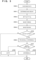
- FIG. 3 is a flowchart related to target temperature setting control. Note that FIG. 3 illustrates processing in a case where an image defect to be detected is a hot offset.
- the hot offset is an image defect generated because the toner of the recording material P adheres to the fixing film 31 to cause the adhering toner to be transferred again to the recording material P.
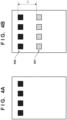
- FIG. 4A is an image indicated by image data
- FIG. 4B illustrates a state in which a hot offset has occurred in the image formed based on the image data.
- the hot offset occurs because the temperature of the fixing film 31 increases due to thinning of the surface layer of the fixing film 31.
- the engine control unit 2010 controls the temperature of the fixing heater 33 so as to become the target temperature, but when thinning of the surface layer of the fixing film 31 occurs, the temperature of the fixing film 31 when the fixing heater 33 is brought to the target temperature may be higher than the appropriate range. In this case, the hot offset occurs.
- the engine control unit 2010 When receiving a print job, the engine control unit 2010 performs the processing in FIG. 3 each time image data of an image to be formed in one recording material is received from the controller 1000. First, the engine control unit 2010 stores image data received from the controller 1000 in the HDD 2245 in S100. In S101, the engine control unit 2010 determines a basis weight of the recording material P based on a detection result of the recording material P by the media sensor 40 when the recording material P reaches a detection region of the media sensor 40. The determined basis weight of the recording material P is stored in the HDD 2245.
- the setting unit 2043 first determines a base temperature Tb (base value) corresponding to the basis weight determined in S101.
- FIG. 5A shows a correspondence relationship between the basis weight and the base temperature Tb.
- the basis weight is evaluated by using two threshold values in three levels. In this example, the two respective threshold values are "65" and "100".
- the base temperature Tb corresponding to the basis weight of "80" in FIG. 5A is 180.
- the setting unit 2043 manages a correction temperature ⁇ T (correction value) for each basis weight level (three in this example). An initial value of the correction temperature ⁇ T for each level is 0.
- the setting unit 2043 sets a target temperature Tg of the fixing heater 33 to a value obtained by subtracting the correction temperature ⁇ T of the level to which the basis weight belongs, from the base temperature Tb corresponding to the basis weight determined in S101.
- the engine control unit 2010 forms an image on the recording material based on the image data while controlling the temperature of the fixing heater 33 so as to become the target temperature Tg.
- the engine control unit 2010 causes the reader 2050 to read the image on the recording material P, acquires the read image data, and stores the read image data in the HDD 2245.
- the comparison unit 2042 compares the image data stored in the HDD 2245 with the read image data, and determines whether a hot offset has occurred based on the comparison result.
- the engine control unit 2010 determines that a hot offset has not occurred, the engine control unit 2010 terminates the processing in FIG. 3 . In this case, the correction temperature ⁇ T belonging to the level of the basis weight of the recording material P on which the image has been formed is not changed. On the other hand, in a case where the engine control unit 2010 determines that a hot offset has occurred, the engine control unit 2010 provisionally determines, in S106, the correction temperature ⁇ T that belongs to the level of the basis weight of the recording material P on which the image has been formed. A method of determining the updated correction temperature ⁇ T will be described below using FIG. 6 . As illustrated in FIG.
- a surface temperature of the fixing film 31 and a density of a hot offset are in a proportional relationship. Additionally, the hot offset does not occur when the surface temperature of the fixing film 31 is lower than or equal to a threshold temperature Ts.
- the engine control unit 2010 determines a density d1 of toner that has adhered to the recording material P due to the hot offset, and estimates a surface temperature T1 of the fixing film 31 from the relationship illustrated in FIG. 6 . Then, in S 106, the engine control unit 2010 provisionally determines a difference between the estimated surface temperature T1 and the threshold temperature Ts as the updated corrected temperature ⁇ T.
- a configuration may be applicable in which a value obtained by adding a predetermined margin to the difference between the estimated surface temperature T1 and the threshold temperature Ts is provisionally determined as the correction temperature ⁇ T.
- the correction temperature ⁇ T has been determined based on the density of the toner that has adhered to the recording material P due to the hot offset, but an area of the toner that has adhered to the recording material P due to the hot offset can be also used.
- an upper limit is provided for an absolute value of the correction temperature ⁇ T for each level.
- FIG. 5B shows an example of the upper limit value for each level.
- the lower the basis weight is, the larger the upper limit value is set.
- the reason why the lower the basis weight is, the larger the upper limit value is set is that the occurrence of adverse effects according to the correction temperature ⁇ T varies depending on the basis weight of the recording material P. Specifically, in a case of a relatively thin recording material P having a small basis weight, the fixing margin with respect to the fixing temperature is large, and thus, even when the correction temperature ⁇ T is made large, the adverse effects are small. On the other hand, in a case of a relatively thick recording material P having a large basis weight, the fixing margin with respect to the fixing temperature is small, and the adverse effects may occur when the correction temperature ⁇ T is made large.
- the engine control unit 2010 determines, in S107, whether or not the provisionally determined correction temperature ⁇ T is within the upper limit. When the provisionally determined correction temperature ⁇ T is within the upper limit value, the engine control unit 2010 updates, in S108, the correction temperature ⁇ T to the correction temperature ⁇ T determined in S 106. On the other hand, when the provisionally determined correction temperature ⁇ T exceeds the upper limit value, the engine control unit 2010 notifies the user of the occurrence of the image defect and the replacement of the fixing device 30 via the notification unit 1020 of the controller 1000. Note that in this case, the processing in FIG. 3 is terminated without updating the correction temperature ⁇ T.
- the present invention can be similarly applied to an image defect generated by a decrease in the fixing temperature.
- an image defect void image
- the target temperature Tg is determined by adding the correction temperature ⁇ T to the base temperature Tb.
- the correction temperature ⁇ T for each level is provided with an upper limit value as illustrated in FIG. 5C .
- the reason why the larger the basis weight is, the larger the upper limit value of the correction temperature ⁇ T is set is that, as the basis weight is small, the resistance to thermal stress deteriorates, so that increasing the correction temperature ⁇ T increases the possibility of the occurrence of adverse effects such as curling or winding around the fixing device 30.
- the base temperature Tb corresponding to the basis weight of the recording material P is corrected by the correction temperature ⁇ T to be set as the target temperature Tg of the fixing heater 33.
- the correction temperature ⁇ T is set based on the degree of the image defect.
- the image defect is determined by reading the image formed on the recording material P.
- the upper limit value of the correction temperature ⁇ T is provided corresponding to the basis weight.
- the determination and update of the correction temperature ⁇ T may be performed each time an image is formed on the predetermined number of recording materials P. Additionally, the occurrence of an image defect is determined each time an image is formed on the recording material P, and the correction temperature ⁇ T is determined, but a configuration may be applicable in which each time an image is successively formed on the predetermined number of recording materials P, the correction temperature ⁇ T is updated to an average value of the correction temperature ⁇ T determined each time. As a result, the frequency of changing the image forming conditions can be made moderate.
- the basis weight of the recording material P is used as property information related to the properties of the recording material P, but a configuration may be applicable in which the roughness and glossiness of the surface of the recording material P are used as the property information.
- the target temperature of the fixing heater 33 is controlled, but the present invention can also be applied to setting of other control values such as the secondary transfer bias voltage. That is, the control value related to the image forming operation is not limited to the target temperature of the fixing heater 33 described in the present embodiment, and can be, for example, a target value of the secondary transfer bias voltage.
- the present invention can also be applied not only to the color image forming apparatus illustrated in FIG. 1 , but also to a monochrome image forming apparatus.
- the present invention is applicable not only to an electrophotographic image forming apparatus, but also to ink ejection control and the like of an ink-jet image forming apparatus.
- the second embodiment will be described focusing on differences from the first embodiment.
- the type of an image defect is determined by comparing image data to read image data, and a control target is selected based on the determined type of the image defect and the basis weight.
- FIG. 7 An example is shown in FIG. 7 .
- the fixing temperature is controlled when the basis weight of the recording material P is smaller than 80. In other words, this is similar to the first embodiment.
- the fixing temperature is controlled when the basis weight of the recording material P is equal to or larger than 80.
- the basis weight of the recording material P is smaller than 80, control of the secondary transfer bias voltage is performed under estimation that a so-called secondary transfer defect has occurred, rather than the fixing failure.
- the secondary transfer bias voltage can be controlled in advance to quickly identify the cause and to correct the control.
- control target is changed based on a combination of the type of the image defect, that is, a comparison result by the comparison unit 2042, and the property information of the recording material. According to this configuration, it is possible to quickly perform the identification of the cause of the image defect and the correction control.
- a third embodiment will be described focusing on differences from the first embodiment and the second embodiment.
- a plurality of image forming apparatuses 101, and 111 to 114, and an HDD apparatus 120 are connected to a LAN 1013.
- the image forming apparatus 101 is similar to the image forming apparatus described in the first embodiment and the second embodiment.
- the image forming apparatuses 111 to 114 have differences from the image forming apparatus 101.
- FIG. 9 indicates differences between the image forming apparatus 101 and each of the image forming apparatuses 111 to 114.
- the image forming apparatus 111 differs from the image forming apparatus 101 in that the image forming apparatus 111 does not have the reader 2050.
- the image forming apparatus 112 differs from the image forming apparatus 101 in that the image forming apparatus 112 does not have the reader 2050 and the media sensor 40.
- the image forming apparatus 113 has a different image forming configuration from the image forming apparatus 101, and differs from the image forming apparatus 101 in that the image forming apparatus 113 does not include the reader 2050.
- the image forming apparatus 114 has a different image forming configuration from the image forming apparatus 101, and differs from the image forming apparatus 101 in that the image forming apparatus 114 does not include the reader 2050 and the media sensor 40.
- the different image forming configuration means that, for example, the configuration itself related to image forming, such as transferring a toner image directly from each of the photoconductors 1 to the recording material P without using the intermediate transfer belt 8, is different.
- the different image forming configuration also means that the configuration itself is basically similar to that in FIG. 1 , but the configurations and materials of the respective members are different.
- the image forming apparatus 101 stores, in the HDD apparatus 120 via the LAN 1013, history data indicating a relationship between the correction temperature ⁇ T associated with the level of the basis weight and the number of recording materials P (hereinafter, the cumulative number) on which an image has been formed.
- Each of the image forming apparatuses 111 to 114 can acquire the history data indicating the relationship between the cumulative number stored in the HDD apparatus 120 and the correction temperature ⁇ T via the LAN 1013. Note that, as described in the first embodiment, the correction temperature ⁇ T varies according to the level of the basis weight.
- the image forming apparatus 111 Since the image forming apparatus 111 does not have the reader 2050, the image forming apparatus 111 cannot determine an image defect by using read image data. However, since the image forming apparatus 111 includes the media sensor 40, the image forming apparatus 111 can acquire the basis weight of the recording material P. Accordingly, the image forming apparatus 111 can determine the correction temperature ⁇ T according to the basis weight based on the history data acquired from the HDD apparatus 120. Note that the correction temperature ⁇ T to be used is a value corresponding to the cumulative number in the image forming apparatus 111.
- the image forming apparatus 112 Since the image forming apparatus 112 does not have the media sensor 40, the image forming apparatus 112 cannot detect the basis weight of the recording material P.
- a managed print service hereinafter, abbreviated as MPS
- MPS a managed print service
- management may be performed by a "management user" providing the service, together with the management of recording mediums.
- the image forming apparatus 112 can determine the correction temperature ⁇ T based on the history data stored in the HDD apparatus 120.
- the correction temperature ⁇ T can be determined based on the history data stored in the HDD apparatus 120 and the basis weight corresponding to the type.
- the image forming apparatus 113 has the media sensor 40, and thus, can acquire the basis weight of the recording material P.
- the correction temperature ⁇ T used by the image forming apparatus 101 cannot be used as it is.
- the image forming apparatus 113 can determine the correction temperature ⁇ T.
- the image forming apparatus 114 Since the image forming apparatus 114 does not have the media sensor 40, the image forming apparatus 114 cannot detect the basis weight of the recording material P, and has a different image forming configuration from that of the image forming apparatus 101, similarly to the image forming apparatus 113. However, similarly to the image forming apparatus 112, when the type of the recording material P to be used in the office is assumed to be the same, the image forming apparatus 114 can determine the basis weight. Additionally, similarly to the image forming apparatus 113, the correction temperature ⁇ T stored in the HDD apparatus 120 can be converted and used.
- a first image forming apparatus stores, in the HDD apparatus 120, the history data indicating the relationship among the cumulative number, the correction temperature ⁇ T, and the basis weight (properties) of the recording material.
- the correction temperature ⁇ T can be determined based on the basis weight of the recording material on which an image is formed and the cumulative number.
- the correction temperature ⁇ T can be determined based on the basis weight of the recording materials on which an image is formed and the cumulative number.
- the third image forming apparatus converts the correction temperature ⁇ T stored in the HDD apparatus 120 in accordance with a predetermined conversion method.
- the conversion method is predetermined based on differences in image forming configuration between the first image forming apparatus and the third image forming apparatus.
- the correction temperature ⁇ T can be determined based on the cumulative number.
- the image forming apparatuses 111 to 114 acquire the correction temperature ⁇ T by accessing the image forming apparatus 101.
- the image forming apparatus 101 provides the history data to the image forming apparatuses 111 to 114.
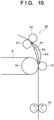
- FIG. 10 illustrates a portion from the registration rollers 16 to the fixing device 30.
- the recording material P is deflected between the secondary transfer roller 11 and the fixing device 30 as illustrated by a reference sign P1 (an arching state P1) in FIG. 10 (hereinafter, referred to as arching control).
- the arching control is performed by adjusting a rotational speed of the pressure roller 32.
- the pressure roller 32 that has exceeded an expected lifetime may reduce the rubber hardness, and reduce the outer diameter.
- FIG. 11A is an image that is indicated by image data
- FIG. 11B is an image that is indicated by image data
- FIG. 11B illustrates a state in which transfer blur occurs in the image that is indicated by the image data illustrated in FIG. 11A .
- expansion and contraction of the image occur at a position at a distance L2 from the rear end of the recording material P.
- the distance L2 is a distance between the registration rollers 16 and the secondary transfer roller 11.
- a stripe-like density difference 650 occurs in a direction orthogonal to the conveyance direction of the recording material.
- the transfer blur infrequently occurs in the arching state P3 when the image forming apparatus is unexpectedly used, such as when the image forming apparatus continues to be used over its expected lifetime. That is, unless the image forming apparatus is unexpectedly used, the transfer blur does not occur in a case where the basis weight w is equal to or smaller than 80.
- transfer blur does not occur in the arching state P1, but transfer blur occurs in the arching states P2 and P3.
- whether or not transfer blur occurs depends on, in addition to the degree of arching state, the basis weight of the recording material. This is because the stress stored in the recording material in the arching state increases as the basis weight increases.
- the correction control in which the rotational speed of the pressure roller 32 is made larger than the reference rotational speed is performed to suppress the transfer blur.
- the rotational speed of the pressure roller 32 is corrected. Note that, in the case of the arching state P2, the rotational speed of the pressure roller 32 is made 5% faster than the reference rotational speed. On the other hand, in the case of the arching state P3, the rotational speed of the pressure roller 32 is made 10% faster than the reference rotational speed. Note that, in the case of the arching state P1, the correction is not performed because transfer blur does not occur.
- FIG. 13 is a flow chart related to rotational speed setting control of the pressure roller 32.
- the engine control unit 2010 performs processing in FIG. 13 each time image data is received from the controller 1000.
- the engine control unit 2010 stores the image data received from the controller 1000 in the HDD 2245, in S200.
- the engine control unit 2010 determines the basis weight of the recording material P based on the detection result of the recording material P by the media sensor 40 when the recording material P reaches the detection region of the media sensor 40 in S201, and determines whether the recording medium P is a plain paper sheet or a cardboard sheet in S202.
- the setting unit 2043 sets a target rotational speed Sg to a base rotational speed Sb (base value) in S211.
- the setting unit 2043 sets the target rotational speed Sg to a speed obtained by adding a correction value ⁇ S to the base rotational speed Sb in S203.
- the correction value ⁇ S is a value indicating an increasing amount of the base rotational speed Sb, and its initial value is 0.
- the engine control unit 2010, in S204 forms an image on the recording material based on the image data while controlling the rotational speed of the pressure roller 32 so as to become the target rotational speed Sg.
- the engine control unit 2010 causes the reader 2050 to read the image on the recording material P, acquires the read image data, and stores the read image data in the HDD 2245.
- the comparison unit 2042 compares the image data stored in the HDD 2245 with the read image data to determine whether transfer blur has occurred or not.
- the comparison unit 2042 can determine that the transfer blur has occurred when a density difference, which is not present in the image based on the original image data, occurs in the image based on the read image data in a width direction orthogonal to the conveyance direction. Note that the density difference in the width direction occurs at around the distance L2 from the rear end of the recording material, so the comparison unit 2042 can determine whether or not the transfer blur has occurred by determining whether or not the density difference occurs at around the distance L2 from the rear end of the recording material.
- the engine control unit 2010 determines that the transfer blur has not occurred, the engine control unit 2010 terminates the processing in FIG. 13 . In this case, the correction value ⁇ S is not changed.
- the engine control unit 2010 determines whether the recording material being conveyed in S207 is the cardboard sheet or the plain paper sheet. Since the correction value ⁇ S is for the cardboard sheet, when the recording material is the plain paper sheet, the engine control unit 2010 terminates the processing in FIG. 13 . Note that, in this case, the engine control unit 2010 stores, in the HDD 2245, the fact that the transfer blur has occurred in the plain paper sheet.
- the engine control unit 2010 provisionally determines the correction value ⁇ S in S208.
- the engine control unit 2010 can determine only whether or not the transfer blur has occurred, and cannot determine whether the arching state is P2 or P3.
- whether the arching state is P2 or P3 is determined depending on whether or not the transfer blur has occurred in the plain paper sheet. Specifically, when information about the fact that the transfer blur has occurred in the plain paper sheet is stored in the HDD 2245, the engine control unit 2010 determines that the arching state is P3.
- the engine control unit 2010 determines that the arching state is P3 in a case where the transfer blur has occurred in both the plain paper sheet and the cardboard sheet. Thus, as shown in FIG. 12B , the correction value ⁇ S is increased by 10%. On the other hand, when the information about the fact that the transfer blur has occurred in the plain paper sheet is not stored in the HDD 2245, the engine control unit 2010 determines that the arching state is P2. Thus, the correction value ⁇ S is increased by 5% as shown in FIG. 12B .
- the upper limit value of the correction value ⁇ S is also provided in the present embodiment. This is because, when the rotational speed of the pressure roller 32 is too high, adverse effects such as image rubbing due to excessive pulling of the recording material may easily occur.
- the engine control unit 2010 determines whether or not the provisionally determined correction value ⁇ S is within the upper limit value in S209. When the provisionally determined correction value ⁇ S is within the upper limit value, the engine control unit 2010, in S210, updates the correction value ⁇ S to the correction value ⁇ S determined in S208.
- the provisionally determined correction value ⁇ S exceeds the upper limit value
- the user is notified of the occurrence of the image defect and the replacement of the fixing device 30 and/or each of the conveyance rollers, via the notification unit 1020 of the controller 1000. Note that, in this case, the processing in FIG. 13 is terminated without updating the correction value ⁇ S.
- the correction value for the control value related to the image forming is determined based on the basis weight of the recording material. According to this configuration, the occurrence of an image defect different from the determined image defect can be suppressed.
- the levels of the basis weight can be any two or more levels.
- the basis weight of the recording material is used as property information, but the thickness or stiffness of the recording material may also be used as the property information. For example, even when the basis weight is the same, since there is a recording material having different stiffness because of the material and the method, any number of combinations among the basis weight, thickness, and stiffness of the recording material can be used as the property information.
- FIG. 14A illustrates an example of the detection image.
- the detection image has an image C1 for detecting a hot offset and a halftone image C2 for detecting transfer blur.
- a reference sign of 551 denotes toner that has adhered to the recording material due to a hot offset
- a reference sign of 650 denotes a region where a density difference occurs due to transfer blur.
- Embodiment(s) of the present invention can also be realized by a computer of a system or apparatus that reads out and executes computer executable instructions (e.g., one or more programs) recorded on a storage medium (which may also be referred to more fully as a 'non-transitory computer-readable storage medium') to perform the functions of one or more of the above-described embodiment(s) and/or that includes one or more circuits (e.g., application specific integrated circuit (ASIC)) for performing the functions of one or more of the above-described embodiment(s), and by a method performed by the computer of the system or apparatus by, for example, reading out and executing the computer executable instructions from the storage medium to perform the functions of one or more of the above-described embodiment(s) and/or controlling the one or more circuits to perform the functions of one or more of the above-described embodiment(s).
- computer executable instructions e.g., one or more programs
- a storage medium which may also be referred to more fully as
- the computer may comprise one or more processors (e.g., central processing unit (CPU), micro processing unit (MPU)) and may include a network of separate computers or separate processors to read out and execute the computer executable instructions.
- the computer executable instructions may be provided to the computer, for example, from a network or the storage medium.
- the storage medium may include, for example, one or more of a hard disk, a random-access memory (RAM), a read only memory (ROM), a storage of distributed computing systems, an optical disk (such as a compact disc (CD), digital versatile disc (DVD), or Blu-ray Disc (BD) TM ), a flash memory device, a memory card, and the like.
Landscapes
- Physics & Mathematics (AREA)
- General Physics & Mathematics (AREA)
- Engineering & Computer Science (AREA)
- Microelectronics & Electronic Packaging (AREA)
- Health & Medical Sciences (AREA)
- Biomedical Technology (AREA)
- General Health & Medical Sciences (AREA)
- Multimedia (AREA)
- Signal Processing (AREA)
- Control Or Security For Electrophotography (AREA)
- Fixing For Electrophotography (AREA)
Claims (8)
- Bilderzeugungsgerät (101), das Folgendes aufweist:eine Bilderzeugungseinrichtung, die angeordnet ist, um ein Bild auf einem Aufzeichnungsmaterial (P) auf der Grundlage von ersten Bilddaten zu erzeugen;eine Steuerungseinrichtung (2010), die angeordnet ist, um einen Bilderzeugungsbetrieb durch die Bilderzeugungseinrichtung zu steuern;eine Ermittlungseinrichtung (40), die angeordnet ist, um Eigenschaftsinformationen in Bezug auf eine Eigenschaft des Aufzeichnungsmaterials (P) zu ermitteln;eine Festlegungseinrichtung (2043), die gestaltet ist, um einen in dem Bilderzeugungsbetrieb zu verwendenden Steuerungswert auf einen Basiswert auf der Grundlage der Eigenschaftsinformationen, die durch die Ermittlungseinrichtung (40) ermittelt werden, festzulegen;eine Leseeinrichtung (2050), die angeordnet ist, um ein Bild, das auf dem Aufzeichnungsmaterial (P) durch die Bilderzeugungseinrichtung erzeugt wird, zu lesen und um zweite Bilddaten auszugeben; undeine Vergleichseinrichtung (2042), die gestaltet ist, um die ersten Bilddaten mit den zweiten Bilddaten zu vergleichen,wobei die Festlegungseinrichtung (2043) des Weiteren gestaltet ist, um einen Korrekturwert auf der Grundlage eines Vergleichsergebnisses zu bestimmen,wobeidie Festlegungseinrichtung (2043) des Weiteren gestaltet ist, um den Steuerungswert auf der Grundlage des Basiswerts und des Korrekturwerts zu ändern,das Bilderzeugungsgerät (101) des Weiteren eine Benachrichtigungseinrichtung (1020) aufweist,ein oberer Grenzwert, der zu den Eigenschaftsinformationen korrespondiert, für den Korrekturwert festgelegt ist,in einem Fall, in dem der Korrekturwert den oberen Grenzwert überschreitet, die Festlegungseinrichtung (2043) gestaltet ist, um den Steuerungswert nicht zu ändern, und die Benachrichtigungseinrichtung (1020) gestaltet ist, um einen Anwender über Informationen in Bezug auf das Vergleichsergebnis zu benachrichtigen, und in einem Fall, in dem der Korrekturwert den oberen Grenzwert nicht überschreitet, die Festlegungseinrichtung (2043) gestaltet ist, um den Steuerungswert auf der Grundlage des Basiswerts und des Korrekturwerts zu ändern.
- Bilderzeugungsgerät (101) nach Anspruch 1, das des Weiteren Folgendes aufweist:eine Speichereinrichtung (2245), die angeordnet ist, um historische Daten zu speichern, die ein Verhältnis zwischen einer kumulativen Anzahl von Aufzeichnungsmaterialien (P), auf denen die Bilderzeugungseinrichtung ein Bild erzeugt, den Eigenschaftsinformationen des Aufzeichnungsmaterials (P) und dem Korrekturwert anzeigen; undeine Bereitstellungseinrichtung, die angeordnet ist, um die historischen Daten, die durch die Speichereinrichtung (2245) gespeichert sind, auf einem anderen Bilderzeugungsgerät (111, 112, 113, 114), das über ein Netzwerk (1013) verbunden ist, bereitzustellen.
- Bilderzeugungsgerät (101) nach Anspruch 1, das des Weiteren Folgendes aufweist:
eine Speichereinrichtung (2245), die angeordnet ist, um historische Daten zwischen einer kumulativen Anzahl von Aufzeichnungsmaterialien (P), auf denen die Bilderzeugungseinrichtung ein Bild erzeugt, den Eigenschaftsinformationen des Aufzeichnungsmaterials (P) und dem Korrekturwert in einem externen Gerät zu speichern, das über ein Netzwerk (1013) verbunden ist. - Bilderzeugungsgerät (101) nach einem der Ansprüche 1 bis 3, wobei
die Eigenschaftsinformationen zumindest eines von einem Basisgewicht, einer Dicke und einer Festigkeit des Aufzeichnungsmaterials (P) umfassen. - Bilderzeugungsgerät (101) nach einem der Ansprüche 1 bis 4, wobeidie Bilderzeugungseinrichtung Folgendes aufweist:eine Übertragungseinrichtung (1, 6, 8, 11), die angeordnet ist, um ein Bild auf das Aufzeichnungsmaterial (P) zu übertragen,eine Fixierungseinrichtung (30), die angeordnet ist, um auf dem Aufzeichnungsmaterial (P) das Bild, das auf das Aufzeichnungsmaterial (P) übertragen ist, zu fixieren, undder Steuerungswert eine Solltemperatur eines Heizbauteils (33) der Fixierungseinrichtung (30) ist.
- Bilderzeugungsgerät (101) nach Anspruch 5, wobeidie Eigenschaftsinformationen ein Basisgewicht des Aufzeichnungsmaterials (P) umfassen, undwenn die Festlegungseinrichtung (2043) den Steuerungswert auf einen Wert festlegt, der größer ist als der Basiswert, indem der Korrekturwert zu dem Basiswert addiert wird, da das Basisgewicht klein ist, der obere Grenzwert klein wird, undwenn die Festlegungseinrichtung (2043) den Steuerungswert auf einen Wert festlegt, der kleiner ist als der Basiswert, indem der Korrekturwert von dem Basiswert subtrahiert wird, da das Basisgewicht klein ist, der obere Grenzwert groß wird.
- Bilderzeugungsgerät (101) nach einem der Ansprüche 1 bis 6, wobeidie Festlegungseinrichtung (2043) eine Vielzahl von Arten der in dem Bilderzeugungsbetrieb zu verwendenden Steuerungswerte festlegt, unddie Festlegungseinrichtung (2043) des Weiteren gestaltet ist, um eine Art, deren Festlegung zu aktualisieren ist, aus der Vielzahl von Arten auf der Grundlage des Vergleichsergebnisses zum Vergleichen der ersten Bilddaten mit den zweiten Bilddaten und den Eigenschaftsinformationen auszuwählen, und um den Steuerungswert der ausgewählten Art festzulegen.
- Bilderzeugungsgerät (101) nach einem der Ansprüche 1 bis 7, wobei
die Vergleichseinrichtung (2043) des Weiteren gestaltet ist, um zu bestimmen, ob ein Bildfehler in einem Bild, das auf dem Aufzeichnungsmaterial durch die Bilderzeugungseinrichtung erzeugt ist, aufgetreten ist oder nicht, indem die ersten Bilddaten mit den zweiten Bilddaten verglichen werden.
Applications Claiming Priority (1)
| Application Number | Priority Date | Filing Date | Title |
|---|---|---|---|
| JP2020038118A JP7449122B2 (ja) | 2020-03-05 | 2020-03-05 | 画像形成装置 |
Publications (3)
| Publication Number | Publication Date |
|---|---|
| EP3876038A2 EP3876038A2 (de) | 2021-09-08 |
| EP3876038A3 EP3876038A3 (de) | 2021-09-22 |
| EP3876038B1 true EP3876038B1 (de) | 2024-10-16 |
Family
ID=74858271
Family Applications (1)
| Application Number | Title | Priority Date | Filing Date |
|---|---|---|---|
| EP21160627.2A Active EP3876038B1 (de) | 2020-03-05 | 2021-03-04 | Zur einstellung eines kontrollwerts konfigurierte bilderzeugungsvorrichtung |
Country Status (3)
| Country | Link |
|---|---|
| US (1) | US11675302B2 (de) |
| EP (1) | EP3876038B1 (de) |
| JP (1) | JP7449122B2 (de) |
Families Citing this family (2)
| Publication number | Priority date | Publication date | Assignee | Title |
|---|---|---|---|---|
| JP2023179069A (ja) * | 2022-06-07 | 2023-12-19 | コニカミノルタ株式会社 | 画像形成システム |
| US12293242B2 (en) | 2023-09-28 | 2025-05-06 | Ricoh Company, Ltd. | Printer calibration mechanism |
Family Cites Families (17)
| Publication number | Priority date | Publication date | Assignee | Title |
|---|---|---|---|---|
| JP2005173293A (ja) * | 2003-12-12 | 2005-06-30 | Kyocera Mita Corp | 画像形成装置 |
| JP2005309077A (ja) * | 2004-04-21 | 2005-11-04 | Fuji Xerox Co Ltd | 故障診断方法および故障診断装置、並びに搬送装置および画像形成装置、並びにプログラムおよび記憶媒体 |
| JP2006289951A (ja) * | 2005-03-16 | 2006-10-26 | Seiko Epson Corp | 印刷方法、印刷装置、印刷プログラム、コンピュータ読み取り可能な記録媒体、印刷装置制御プログラム、印刷装置制御方法、印刷用データ生成装置、印刷用データ生成プログラム及び印刷用データ生成方法 |
| JP5164458B2 (ja) | 2007-07-10 | 2013-03-21 | キヤノン株式会社 | 画像形成装置およびその制御方法 |
| JP5157753B2 (ja) * | 2008-08-27 | 2013-03-06 | カシオ計算機株式会社 | 画像処理装置、画像処理方法、画像処理プログラム |
| JP5188339B2 (ja) * | 2008-09-17 | 2013-04-24 | キヤノン株式会社 | 画像形成装置 |
| JP2013033167A (ja) | 2011-08-03 | 2013-02-14 | Canon Inc | 画像形成装置 |
| JP5413432B2 (ja) * | 2011-10-20 | 2014-02-12 | コニカミノルタ株式会社 | 画像形成装置 |
| JP5919788B2 (ja) * | 2011-12-12 | 2016-05-18 | 株式会社リコー | 画像形成装置、印刷システム、画像調整方法 |
| JP2013123812A (ja) * | 2011-12-13 | 2013-06-24 | Canon Inc | 検査装置、検査方法、コンピュータプログラム |
| JP5987566B2 (ja) * | 2012-09-04 | 2016-09-07 | 富士ゼロックス株式会社 | 定着装置及び画像形成装置 |
| US9367005B2 (en) * | 2014-06-04 | 2016-06-14 | Lexmark International, Inc. | Imaging device and method for determining operating parameters |
| JP6521664B2 (ja) | 2015-02-20 | 2019-05-29 | キヤノン株式会社 | 画像形成システム |
| JP2016177095A (ja) * | 2015-03-19 | 2016-10-06 | 富士ゼロックス株式会社 | 画像形成装置 |
| JP6497269B2 (ja) * | 2015-08-19 | 2019-04-10 | コニカミノルタ株式会社 | 画像形成システム及び画像検査方法 |
| JP2019015874A (ja) | 2017-07-07 | 2019-01-31 | コニカミノルタ株式会社 | 画像形成装置、画像形成方法及びプログラム |
| JP7119670B2 (ja) | 2018-07-11 | 2022-08-17 | コニカミノルタ株式会社 | 画像形成装置 |
-
2020
- 2020-03-05 JP JP2020038118A patent/JP7449122B2/ja active Active
-
2021
- 2021-03-04 US US17/192,018 patent/US11675302B2/en active Active
- 2021-03-04 EP EP21160627.2A patent/EP3876038B1/de active Active
Also Published As
| Publication number | Publication date |
|---|---|
| EP3876038A2 (de) | 2021-09-08 |
| EP3876038A3 (de) | 2021-09-22 |
| JP2021140045A (ja) | 2021-09-16 |
| US20210278791A1 (en) | 2021-09-09 |
| JP7449122B2 (ja) | 2024-03-13 |
| US11675302B2 (en) | 2023-06-13 |
Similar Documents
| Publication | Publication Date | Title |
|---|---|---|
| US8918001B2 (en) | Fixing apparatus | |
| US11156944B2 (en) | Image forming apparatus, image forming method, and computer readable recording medium for recording program | |
| US8064816B2 (en) | Printer including a fuser assembly with backup member temperature sensor | |
| US9207593B2 (en) | Image heating apparatus and image forming apparatus | |
| US11385584B2 (en) | Image forming apparatus | |
| US11099508B2 (en) | Image forming apparatus, image forming method, and computer readable recording medium for recording program | |
| US11675302B2 (en) | Image forming apparatus configured to set control value | |
| US8725017B2 (en) | Fuser assembly heater temperature control | |
| US11237504B2 (en) | Image forming apparatus, image forming method, and computer-readable recording medium with program recorded therein | |
| US10712692B2 (en) | Image forming apparatus having sheet loop control | |
| US10656576B2 (en) | Image forming apparatus, image forming system, and image forming method each controlling fixing temperature | |
| JP2003098792A (ja) | カラー画像形成装置の色ずれ補正装置 | |
| JP5611295B2 (ja) | 画像形成装置 | |
| JP5494679B2 (ja) | 定着装置及び画像形成装置 | |
| US11175615B2 (en) | Image forming apparatus, image forming method, and computer readable storage medium storing program capable of setting a target temperature for a page for which image information is not acquired | |
| JP6137050B2 (ja) | 定着装置及び画像形成装置 | |
| JP2014178384A (ja) | 画像形成装置及び画像形成方法 | |
| JP6131470B2 (ja) | 画像形成装置 | |
| JP6095345B2 (ja) | 画像形成装置 | |
| US11300912B2 (en) | Image forming apparatus that detects occurrence of image defect | |
| US20260056500A1 (en) | Image forming apparatus, image forming method, and recording medium | |
| JP2010139817A (ja) | 画像形成装置 | |
| JP7267726B2 (ja) | 画像形成装置 | |
| EP3702842B1 (de) | Bilderzeugungsvorrichtung und verfahren zum betrieb einer bilderzeugungsvorrichtung | |
| JPH07295428A (ja) | 定着装置 |
Legal Events
| Date | Code | Title | Description |
|---|---|---|---|
| PUAI | Public reference made under article 153(3) epc to a published international application that has entered the european phase |
Free format text: ORIGINAL CODE: 0009012 |
|
| STAA | Information on the status of an ep patent application or granted ep patent |
Free format text: STATUS: THE APPLICATION HAS BEEN PUBLISHED |
|
| PUAL | Search report despatched |
Free format text: ORIGINAL CODE: 0009013 |
|
| AK | Designated contracting states |
Kind code of ref document: A2 Designated state(s): AL AT BE BG CH CY CZ DE DK EE ES FI FR GB GR HR HU IE IS IT LI LT LU LV MC MK MT NL NO PL PT RO RS SE SI SK SM TR |
|
| AK | Designated contracting states |
Kind code of ref document: A3 Designated state(s): AL AT BE BG CH CY CZ DE DK EE ES FI FR GB GR HR HU IE IS IT LI LT LU LV MC MK MT NL NO PL PT RO RS SE SI SK SM TR |
|
| RIC1 | Information provided on ipc code assigned before grant |
Ipc: G03G 15/00 20060101ALI20210816BHEP Ipc: G03G 15/20 20060101ALI20210816BHEP Ipc: G03G 15/16 20060101AFI20210816BHEP |
|
| STAA | Information on the status of an ep patent application or granted ep patent |
Free format text: STATUS: REQUEST FOR EXAMINATION WAS MADE |
|
| 17P | Request for examination filed |
Effective date: 20220322 |
|
| RBV | Designated contracting states (corrected) |
Designated state(s): AL AT BE BG CH CY CZ DE DK EE ES FI FR GB GR HR HU IE IS IT LI LT LU LV MC MK MT NL NO PL PT RO RS SE SI SK SM TR |
|
| STAA | Information on the status of an ep patent application or granted ep patent |
Free format text: STATUS: EXAMINATION IS IN PROGRESS |
|
| 17Q | First examination report despatched |
Effective date: 20231108 |
|
| GRAP | Despatch of communication of intention to grant a patent |
Free format text: ORIGINAL CODE: EPIDOSNIGR1 |
|
| STAA | Information on the status of an ep patent application or granted ep patent |
Free format text: STATUS: GRANT OF PATENT IS INTENDED |
|
| INTG | Intention to grant announced |
Effective date: 20240514 |
|
| GRAS | Grant fee paid |
Free format text: ORIGINAL CODE: EPIDOSNIGR3 |
|
| GRAA | (expected) grant |
Free format text: ORIGINAL CODE: 0009210 |
|
| STAA | Information on the status of an ep patent application or granted ep patent |
Free format text: STATUS: THE PATENT HAS BEEN GRANTED |
|
| AK | Designated contracting states |
Kind code of ref document: B1 Designated state(s): AL AT BE BG CH CY CZ DE DK EE ES FI FR GB GR HR HU IE IS IT LI LT LU LV MC MK MT NL NO PL PT RO RS SE SI SK SM TR |
|
| REG | Reference to a national code |
Ref country code: GB Ref legal event code: FG4D |
|
| REG | Reference to a national code |
Ref country code: CH Ref legal event code: EP |
|
| REG | Reference to a national code |
Ref country code: IE Ref legal event code: FG4D |
|
| REG | Reference to a national code |
Ref country code: DE Ref legal event code: R096 Ref document number: 602021020210 Country of ref document: DE |
|
| REG | Reference to a national code |
Ref country code: LT Ref legal event code: MG9D |
|
| REG | Reference to a national code |
Ref country code: NL Ref legal event code: MP Effective date: 20241016 |
|
| REG | Reference to a national code |
Ref country code: AT Ref legal event code: MK05 Ref document number: 1733401 Country of ref document: AT Kind code of ref document: T Effective date: 20241016 |
|
| PG25 | Lapsed in a contracting state [announced via postgrant information from national office to epo] |
Ref country code: NL Free format text: LAPSE BECAUSE OF FAILURE TO SUBMIT A TRANSLATION OF THE DESCRIPTION OR TO PAY THE FEE WITHIN THE PRESCRIBED TIME-LIMIT Effective date: 20241016 |
|
| PG25 | Lapsed in a contracting state [announced via postgrant information from national office to epo] |
Ref country code: NL Free format text: LAPSE BECAUSE OF FAILURE TO SUBMIT A TRANSLATION OF THE DESCRIPTION OR TO PAY THE FEE WITHIN THE PRESCRIBED TIME-LIMIT Effective date: 20241016 |
|
| PG25 | Lapsed in a contracting state [announced via postgrant information from national office to epo] |
Ref country code: PT Free format text: LAPSE BECAUSE OF FAILURE TO SUBMIT A TRANSLATION OF THE DESCRIPTION OR TO PAY THE FEE WITHIN THE PRESCRIBED TIME-LIMIT Effective date: 20250217 Ref country code: IS Free format text: LAPSE BECAUSE OF FAILURE TO SUBMIT A TRANSLATION OF THE DESCRIPTION OR TO PAY THE FEE WITHIN THE PRESCRIBED TIME-LIMIT Effective date: 20250216 Ref country code: HR Free format text: LAPSE BECAUSE OF FAILURE TO SUBMIT A TRANSLATION OF THE DESCRIPTION OR TO PAY THE FEE WITHIN THE PRESCRIBED TIME-LIMIT Effective date: 20241016 |
|
| PG25 | Lapsed in a contracting state [announced via postgrant information from national office to epo] |
Ref country code: FI Free format text: LAPSE BECAUSE OF FAILURE TO SUBMIT A TRANSLATION OF THE DESCRIPTION OR TO PAY THE FEE WITHIN THE PRESCRIBED TIME-LIMIT Effective date: 20241016 |
|
| PG25 | Lapsed in a contracting state [announced via postgrant information from national office to epo] |
Ref country code: BG Free format text: LAPSE BECAUSE OF FAILURE TO SUBMIT A TRANSLATION OF THE DESCRIPTION OR TO PAY THE FEE WITHIN THE PRESCRIBED TIME-LIMIT Effective date: 20241016 |
|
| PG25 | Lapsed in a contracting state [announced via postgrant information from national office to epo] |
Ref country code: ES Free format text: LAPSE BECAUSE OF FAILURE TO SUBMIT A TRANSLATION OF THE DESCRIPTION OR TO PAY THE FEE WITHIN THE PRESCRIBED TIME-LIMIT Effective date: 20241016 |
|
| PG25 | Lapsed in a contracting state [announced via postgrant information from national office to epo] |
Ref country code: NO Free format text: LAPSE BECAUSE OF FAILURE TO SUBMIT A TRANSLATION OF THE DESCRIPTION OR TO PAY THE FEE WITHIN THE PRESCRIBED TIME-LIMIT Effective date: 20250116 |
|
| PG25 | Lapsed in a contracting state [announced via postgrant information from national office to epo] |
Ref country code: GR Free format text: LAPSE BECAUSE OF FAILURE TO SUBMIT A TRANSLATION OF THE DESCRIPTION OR TO PAY THE FEE WITHIN THE PRESCRIBED TIME-LIMIT Effective date: 20250117 Ref country code: LV Free format text: LAPSE BECAUSE OF FAILURE TO SUBMIT A TRANSLATION OF THE DESCRIPTION OR TO PAY THE FEE WITHIN THE PRESCRIBED TIME-LIMIT Effective date: 20241016 Ref country code: AT Free format text: LAPSE BECAUSE OF FAILURE TO SUBMIT A TRANSLATION OF THE DESCRIPTION OR TO PAY THE FEE WITHIN THE PRESCRIBED TIME-LIMIT Effective date: 20241016 |
|
| PG25 | Lapsed in a contracting state [announced via postgrant information from national office to epo] |
Ref country code: PL Free format text: LAPSE BECAUSE OF FAILURE TO SUBMIT A TRANSLATION OF THE DESCRIPTION OR TO PAY THE FEE WITHIN THE PRESCRIBED TIME-LIMIT Effective date: 20241016 |
|
| PG25 | Lapsed in a contracting state [announced via postgrant information from national office to epo] |
Ref country code: RS Free format text: LAPSE BECAUSE OF FAILURE TO SUBMIT A TRANSLATION OF THE DESCRIPTION OR TO PAY THE FEE WITHIN THE PRESCRIBED TIME-LIMIT Effective date: 20250116 |
|
| PG25 | Lapsed in a contracting state [announced via postgrant information from national office to epo] |
Ref country code: SM Free format text: LAPSE BECAUSE OF FAILURE TO SUBMIT A TRANSLATION OF THE DESCRIPTION OR TO PAY THE FEE WITHIN THE PRESCRIBED TIME-LIMIT Effective date: 20241016 |
|
| PG25 | Lapsed in a contracting state [announced via postgrant information from national office to epo] |
Ref country code: DK Free format text: LAPSE BECAUSE OF FAILURE TO SUBMIT A TRANSLATION OF THE DESCRIPTION OR TO PAY THE FEE WITHIN THE PRESCRIBED TIME-LIMIT Effective date: 20241016 |
|
| REG | Reference to a national code |
Ref country code: DE Ref legal event code: R097 Ref document number: 602021020210 Country of ref document: DE |
|
| PG25 | Lapsed in a contracting state [announced via postgrant information from national office to epo] |
Ref country code: EE Free format text: LAPSE BECAUSE OF FAILURE TO SUBMIT A TRANSLATION OF THE DESCRIPTION OR TO PAY THE FEE WITHIN THE PRESCRIBED TIME-LIMIT Effective date: 20241016 |
|
| PG25 | Lapsed in a contracting state [announced via postgrant information from national office to epo] |
Ref country code: RO Free format text: LAPSE BECAUSE OF FAILURE TO SUBMIT A TRANSLATION OF THE DESCRIPTION OR TO PAY THE FEE WITHIN THE PRESCRIBED TIME-LIMIT Effective date: 20241016 |
|
| PG25 | Lapsed in a contracting state [announced via postgrant information from national office to epo] |
Ref country code: SK Free format text: LAPSE BECAUSE OF FAILURE TO SUBMIT A TRANSLATION OF THE DESCRIPTION OR TO PAY THE FEE WITHIN THE PRESCRIBED TIME-LIMIT Effective date: 20241016 |
|
| PG25 | Lapsed in a contracting state [announced via postgrant information from national office to epo] |
Ref country code: CZ Free format text: LAPSE BECAUSE OF FAILURE TO SUBMIT A TRANSLATION OF THE DESCRIPTION OR TO PAY THE FEE WITHIN THE PRESCRIBED TIME-LIMIT Effective date: 20241016 |
|
| PG25 | Lapsed in a contracting state [announced via postgrant information from national office to epo] |
Ref country code: IT Free format text: LAPSE BECAUSE OF FAILURE TO SUBMIT A TRANSLATION OF THE DESCRIPTION OR TO PAY THE FEE WITHIN THE PRESCRIBED TIME-LIMIT Effective date: 20241016 |
|
| PLBE | No opposition filed within time limit |
Free format text: ORIGINAL CODE: 0009261 |
|
| STAA | Information on the status of an ep patent application or granted ep patent |
Free format text: STATUS: NO OPPOSITION FILED WITHIN TIME LIMIT |
|
| PG25 | Lapsed in a contracting state [announced via postgrant information from national office to epo] |
Ref country code: SE Free format text: LAPSE BECAUSE OF FAILURE TO SUBMIT A TRANSLATION OF THE DESCRIPTION OR TO PAY THE FEE WITHIN THE PRESCRIBED TIME-LIMIT Effective date: 20241016 |
|
| 26N | No opposition filed |
Effective date: 20250717 |
|
| PG25 | Lapsed in a contracting state [announced via postgrant information from national office to epo] |
Ref country code: MC Free format text: LAPSE BECAUSE OF FAILURE TO SUBMIT A TRANSLATION OF THE DESCRIPTION OR TO PAY THE FEE WITHIN THE PRESCRIBED TIME-LIMIT Effective date: 20241016 |
|
| REG | Reference to a national code |
Ref country code: CH Ref legal event code: H13 Free format text: ST27 STATUS EVENT CODE: U-0-0-H10-H13 (AS PROVIDED BY THE NATIONAL OFFICE) Effective date: 20251024 |
|
| PG25 | Lapsed in a contracting state [announced via postgrant information from national office to epo] |
Ref country code: LU Free format text: LAPSE BECAUSE OF NON-PAYMENT OF DUE FEES Effective date: 20250304 |
|
| GBPC | Gb: european patent ceased through non-payment of renewal fee |
Effective date: 20250304 |
|
| REG | Reference to a national code |
Ref country code: BE Ref legal event code: MM Effective date: 20250331 |
|
| PG25 | Lapsed in a contracting state [announced via postgrant information from national office to epo] |
Ref country code: GB Free format text: LAPSE BECAUSE OF NON-PAYMENT OF DUE FEES Effective date: 20250304 |
|
| PG25 | Lapsed in a contracting state [announced via postgrant information from national office to epo] |
Ref country code: FR Free format text: LAPSE BECAUSE OF NON-PAYMENT OF DUE FEES Effective date: 20250331 |
|
| PG25 | Lapsed in a contracting state [announced via postgrant information from national office to epo] |
Ref country code: BE Free format text: LAPSE BECAUSE OF NON-PAYMENT OF DUE FEES Effective date: 20250331 |
|
| PG25 | Lapsed in a contracting state [announced via postgrant information from national office to epo] |
Ref country code: CH Free format text: LAPSE BECAUSE OF NON-PAYMENT OF DUE FEES Effective date: 20250331 |
|
| PG25 | Lapsed in a contracting state [announced via postgrant information from national office to epo] |
Ref country code: IE Free format text: LAPSE BECAUSE OF NON-PAYMENT OF DUE FEES Effective date: 20250304 |
|
| PGFP | Annual fee paid to national office [announced via postgrant information from national office to epo] |
Ref country code: DE Payment date: 20260219 Year of fee payment: 6 |