EP3875298B1 - Side vehicle body structure of vehicle - Google Patents
Side vehicle body structure of vehicle Download PDFInfo
- Publication number
- EP3875298B1 EP3875298B1 EP21157980.0A EP21157980A EP3875298B1 EP 3875298 B1 EP3875298 B1 EP 3875298B1 EP 21157980 A EP21157980 A EP 21157980A EP 3875298 B1 EP3875298 B1 EP 3875298B1
- Authority
- EP
- European Patent Office
- Prior art keywords
- vehicle
- side sill
- width
- exhaust
- exhaust system
- Prior art date
- Legal status (The legal status is an assumption and is not a legal conclusion. Google has not performed a legal analysis and makes no representation as to the accuracy of the status listed.)
- Active
Links
- 230000003584 silencer Effects 0.000 claims description 68
- 238000002485 combustion reaction Methods 0.000 claims description 11
- 238000005192 partition Methods 0.000 claims description 6
- 238000001125 extrusion Methods 0.000 claims description 3
- 108010066057 cabin-1 Proteins 0.000 description 22
- 239000000725 suspension Substances 0.000 description 19
- 230000008878 coupling Effects 0.000 description 15
- 238000010168 coupling process Methods 0.000 description 15
- 238000005859 coupling reaction Methods 0.000 description 15
- 230000035939 shock Effects 0.000 description 8
- 238000010521 absorption reaction Methods 0.000 description 6
- 238000003466 welding Methods 0.000 description 6
- 229910000838 Al alloy Inorganic materials 0.000 description 5
- 230000002787 reinforcement Effects 0.000 description 4
- 230000004308 accommodation Effects 0.000 description 3
- 239000013618 particulate matter Substances 0.000 description 2
- 239000004606 Fillers/Extenders Substances 0.000 description 1
- 239000000956 alloy Substances 0.000 description 1
- 230000015572 biosynthetic process Effects 0.000 description 1
- 230000007423 decrease Effects 0.000 description 1
- 230000000694 effects Effects 0.000 description 1
- 230000030279 gene silencing Effects 0.000 description 1
- 230000005484 gravity Effects 0.000 description 1
- 238000000465 moulding Methods 0.000 description 1
Images


Classifications
-
- B—PERFORMING OPERATIONS; TRANSPORTING
- B60—VEHICLES IN GENERAL
- B60K—ARRANGEMENT OR MOUNTING OF PROPULSION UNITS OR OF TRANSMISSIONS IN VEHICLES; ARRANGEMENT OR MOUNTING OF PLURAL DIVERSE PRIME-MOVERS IN VEHICLES; AUXILIARY DRIVES FOR VEHICLES; INSTRUMENTATION OR DASHBOARDS FOR VEHICLES; ARRANGEMENTS IN CONNECTION WITH COOLING, AIR INTAKE, GAS EXHAUST OR FUEL SUPPLY OF PROPULSION UNITS IN VEHICLES
- B60K13/00—Arrangement in connection with combustion air intake or gas exhaust of propulsion units
- B60K13/04—Arrangement in connection with combustion air intake or gas exhaust of propulsion units concerning exhaust
-
- B—PERFORMING OPERATIONS; TRANSPORTING
- B62—LAND VEHICLES FOR TRAVELLING OTHERWISE THAN ON RAILS
- B62D—MOTOR VEHICLES; TRAILERS
- B62D25/00—Superstructure or monocoque structure sub-units; Parts or details thereof not otherwise provided for
- B62D25/02—Side panels
- B62D25/025—Side sills thereof
-
- B—PERFORMING OPERATIONS; TRANSPORTING
- B62—LAND VEHICLES FOR TRAVELLING OTHERWISE THAN ON RAILS
- B62D—MOTOR VEHICLES; TRAILERS
- B62D25/00—Superstructure or monocoque structure sub-units; Parts or details thereof not otherwise provided for
- B62D25/20—Floors or bottom sub-units
- B62D25/2009—Floors or bottom sub-units in connection with other superstructure subunits
- B62D25/2036—Floors or bottom sub-units in connection with other superstructure subunits the subunits being side panels, sills or pillars
-
- F—MECHANICAL ENGINEERING; LIGHTING; HEATING; WEAPONS; BLASTING
- F01—MACHINES OR ENGINES IN GENERAL; ENGINE PLANTS IN GENERAL; STEAM ENGINES
- F01N—GAS-FLOW SILENCERS OR EXHAUST APPARATUS FOR MACHINES OR ENGINES IN GENERAL; GAS-FLOW SILENCERS OR EXHAUST APPARATUS FOR INTERNAL COMBUSTION ENGINES
- F01N13/00—Exhaust or silencing apparatus characterised by constructional features ; Exhaust or silencing apparatus, or parts thereof, having pertinent characteristics not provided for in, or of interest apart from, groups F01N1/00 - F01N5/00, F01N9/00, F01N11/00
- F01N13/001—Gas flow channels or gas chambers being at least partly formed in the structural parts of the engine or machine
-
- F—MECHANICAL ENGINEERING; LIGHTING; HEATING; WEAPONS; BLASTING
- F01—MACHINES OR ENGINES IN GENERAL; ENGINE PLANTS IN GENERAL; STEAM ENGINES
- F01N—GAS-FLOW SILENCERS OR EXHAUST APPARATUS FOR MACHINES OR ENGINES IN GENERAL; GAS-FLOW SILENCERS OR EXHAUST APPARATUS FOR INTERNAL COMBUSTION ENGINES
- F01N13/00—Exhaust or silencing apparatus characterised by constructional features ; Exhaust or silencing apparatus, or parts thereof, having pertinent characteristics not provided for in, or of interest apart from, groups F01N1/00 - F01N5/00, F01N9/00, F01N11/00
- F01N13/009—Exhaust or silencing apparatus characterised by constructional features ; Exhaust or silencing apparatus, or parts thereof, having pertinent characteristics not provided for in, or of interest apart from, groups F01N1/00 - F01N5/00, F01N9/00, F01N11/00 having two or more separate purifying devices arranged in series
-
- F—MECHANICAL ENGINEERING; LIGHTING; HEATING; WEAPONS; BLASTING
- F01—MACHINES OR ENGINES IN GENERAL; ENGINE PLANTS IN GENERAL; STEAM ENGINES
- F01N—GAS-FLOW SILENCERS OR EXHAUST APPARATUS FOR MACHINES OR ENGINES IN GENERAL; GAS-FLOW SILENCERS OR EXHAUST APPARATUS FOR INTERNAL COMBUSTION ENGINES
- F01N2340/00—Dimensional characteristics of the exhaust system, e.g. length, diameter or volume of the apparatus; Spatial arrangements of exhaust apparatuses
- F01N2340/04—Dimensional characteristics of the exhaust system, e.g. length, diameter or volume of the apparatus; Spatial arrangements of exhaust apparatuses characterised by the arrangement of an exhaust pipe, manifold or apparatus in relation to vehicle frame or particular vehicle parts
Definitions
- the present invention relates to a vehicle which includes, for example, an internal combustion engine equipped on the front side of a partition wall defining a front edge of a vehicle cabin space, an exhaust apparatus through which exhaust gas exhausted from the internal combustion engine passes, and a side sill extending along the vehicle front-rear direction on the side of a floor forming a floor surface of the vehicle cabin space.
- an exhaust system member for example, a filter for exhaust treatment, an exhaust pipe, or a silencer
- an exhaust apparatus is provided not at the vehicle-width-direction center under a floor but on the vehicle-width-direction outer side relative to the floor (namely, a lower portion of the vehicle on the vehicle-width-direction outer side).
- the aim of adopting such a configuration is roughly classified into cases where a vehicle body layout property is secured and where a motion performance of a vehicle body is emphasized.
- a vehicle in which, for example, in order to avoid a battery disposed under a floor, an exhaust system member is provided on the vehicle-width-direction outer side relative to the battery under the floor (for example, see Japanese Patent Laid-Open No. 2018-39452 ).
- a vehicle has been known in which, for example, as in a sports car, in order to dispose a heavy object near the center of a vehicle body, an exhaust system member, which is relatively light, is disposed at a lower portion of the vehicle on the vehicle-width-direction outer side.
- the center of gravity of occupants seated on a driver seat and a passenger seat is lowered, or an interval in the vehicle width direction between the driver seat and the passenger seat which are adjacent to each other is narrowed.
- the exhaust system member is disposed at the lower portion of the vehicle on the vehicle-width-direction outer side
- US 2 875 841 A shows an integral vehicle frame and underbody which includes closed channel side rails disposed in parallel spaced relation, tubular members secured within said side rails to opposite side walls thereof and extended the length thereof, a vehicle floor pan secured to said side rails and disposed there between, engine supporting means secured to said floor pan, and exhaust means disposed within said tubular members and adapted to be connected to the exhaust system of a vehicle engine mounted upon said engine supporting means.
- Other vehicles with side sills are known from DE 10 2018 213673 A1 , JP S63 166830 U , JP 2001 115835 A , US 3 495 673 A , and JP 2018 039452 A .
- the present invention has been made in view of such a problem and has an object to provide a vehicle which can, even in a case where an exhaust apparatus (at least one of an exhaust member and an exhaust pipe) is provided on the vehicle-width-direction outer side relative to a side sill, suppress widening of the vehicle.
- an exhaust apparatus at least one of an exhaust member and an exhaust pipe
- a vehicle which includes an internal combustion engine equipped on the front side of a partition wall defining a front edge of a vehicle cabin space, an exhaust apparatus through which exhaust gas exhausted from the internal combustion engine passes, and a side sill extending along the vehicle front-rear direction on the side of a floor forming a floor surface of the vehicle cabin space, wherein the side sill has a recess having a cross section recessed toward the vehicle-width-direction inner side from the vehicle-width-direction outer side in a cross-sectional view orthogonal to the vehicle front-rear direction and extending in the vehicle front-rear direction, and the exhaust apparatus is disposed at the recess.
- the exhaust apparatus even in a case where a vehicle-width-direction inner end of the exhaust apparatus is provided on the vehicle-width-direction outer side relative to a vehicle-width-direction inner end of the side sill, at least a part of the exhaust apparatus in the vehicle width direction can be located in the recess, so that widening of the vehicle can be suppressed.
- the exhaust apparatus which is light, is laid out on the vehicle-width-direction outer side, a heavy object can be laid out at the vehicle center, thus contributing to enhancement of a motion performance of the vehicle.
- the recess is a portion (recessed portion) recessed toward the vehicle-width-direction inner side from the vehicle-width-direction outer side in a cross-sectional view of the side sill which is orthogonal to the vehicle front-rear direction
- the recess is not limited to a portion whose intermediate portion in the vehicle up-down direction is recessed toward the vehicle-width-direction inner side, and may be a portion recessed in a cutout shape from an upper end thereof in the vehicle up-down direction toward the lower side or from a lower end thereof in the vehicle up-down direction toward the upper side.
- At least one of the exhaust system member and the exhaust pipe, which will be described later, can be disposed at the recess.
- the exhaust apparatus has an exhaust pipe and an exhaust system member, and the exhaust system member has a larger cross-sectional area orthogonal to the passing direction of exhaust gas than the exhaust pipe, and is disposed at the recess in such a manner that the passing direction is parallel to the longitudinal direction of the side sill.
- the exhaust system member having the larger cross-sectional area orthogonal to the passing direction of exhaust gas than the exhaust pipe is disposed at the recess in such a manner that the passing direction is substantially parallel to the longitudinal direction of the side sill, so that, in such a case where the exhaust system member is disposed at a vehicle body side portion, widening of the vehicle can be suppressed.
- the exhaust system member is a member through which exhaust gas exhausted from the internal combustion engine passes
- the exhaust system member is not limited to a member such as a GPF including, for example, a filter that treats exhaust gas (gas) from the internal combustion engine and may be, for example, a member having a silencing function such as a silencer or a catalyzer.
- the exhaust system member may include a portion (component) including a connection function for connecting to another exhaust system member or the exhaust pipe.
- an opening through which an occupant enters and exits the vehicle cabin space is formed above the side sill, and the side sill has a side sill upper portion overlapping with the exhaust system member in the vehicle width direction on the upper side relative to the exhaust system member.
- the exhaust system member is covered from above by the side sill upper portion, so that the side sill can function as a heat shielding member against heat release from the exhaust system member.
- the side sill upper portion is a closed cross-sectional structure having a closed cross-sectional space inside.
- the closed cross-sectional space provided inside the side sill upper portion can make the occupant even less likely to feel heat when the occupant enters and exits the vehicle cabin space.
- an eaves is provided which extends outward in the vehicle width direction and downward and covers the exhaust system member from above.
- the side sill upper portion is provided with the eaves extending merely outward in the vehicle width direction and downward from the vehicle-width-direction outer side, so that, while an amount of shielding of heat released upward from the exhaust system member is more enhanced, the shielding range can be more expanded.
- the exhaust system member is extended in the vehicle front-rear direction along a lower edge of the opening and is higher in the vehicle up-down direction on the rear side than on the front side in the vehicle front-rear direction, and the side sill upper portion is higher in the vehicle up-down direction on the rear side than on the front side in the vehicle front-rear direction, such that the side sill upper portion and the exhaust system member have corresponding shapes from a vehicle side view.
- the side sill upper portion is formed so as to be higher on the rear side than on the front side, so that the lower edge of the opening can be formed in such a manner that a front-side portion thereof becomes lower than a rear-side portion thereof. Accordingly, it is possible for the occupant to smoothly enter and exit the vehicle cabin space through the opening.
- the side sill upper portion is formed corresponding to the vehicle side view shape of the exhaust system member, so that the exhaust system member disposed at the recess can be firmly covered from above by the side sill upper portion.
- the side sill can effectively function as a heat shielding member against the heat release from the exhaust system member.
- a vehicle of the present embodiment is a sports car adopting a so-called space frame structure coupling a plurality of extruded frames made of an aluminum alloy and forming a vehicle body framework, and adopting a center pillar-less structure in which a side door is of a two-door type.
- a side vehicle body structure of such a vehicle will be explained with reference to FIGs. 1 to 5 .
- arrow F indicates the vehicle front direction
- arrow R the vehicle right direction
- arrow L the vehicle left direction
- arrow U the vehicle upper direction
- the vehicle including the side vehicle body structure of the present embodiment includes a vehicle cabin 1 for an occupant to get in, a front vehicle body 2 provided on the vehicle front side relative to the vehicle cabin 1, and a rear vehicle body 3 provided on the vehicle rear side relative to the vehicle cabin 1.
- the vehicle cabin 1 and the front vehicle body 2 are partitioned by a dash panel 9 in a raised wall shape.
- the dash panel 9 serves as a partition wall defining a front edge of a vehicle cabin space 1s provided inside the vehicle cabin 1 and is disposed between the vehicle cabin 1 and the front vehicle body 2.
- the vehicle cabin 1 includes a floor panel 4 forming a floor (floor surface) of the vehicle cabin 1, a tunnel frame 5 extending in the vehicle front-rear direction above a center position of the floor panel 4 in the vehicle width direction, a tunnel side frame 6 extending in the vehicle front-rear direction at a corner between a side wall on each of both sides of the tunnel frame 5 and the floor panel 4, and a plurality of floor cross members 7 each coupling the tunnel frame 5 and a side sill 8 in the vehicle width direction.
- both sides of the floor panel 4 of the vehicle cabin 1 in the vehicle width direction include the pair of left and right side sills 8 extending in the vehicle front-rear direction, hinge pillars 11 (front-side pillars) each extending upward from a front end of the side sill 8, and rear pillars 12 (rear-side pillars) each extending upward from a rear end of the side sill 8.
- door openings 13 through which the occupant enters and exits the vehicle cabin 1 are provided.
- a hinge pillar 11, a rear pillar 12, and the side sill 8 are provided along a front edge 13a, rear edge 13b, and lower edge 13c of the door opening 13, respectively.
- the front vehicle body 2 includes a pair of left and right front suspension support members 14 supporting a front suspension (illustration omitted), a plurality of front-side cross members 15 (see FIG. 1 ) each coupling the pair of left and right front suspension support members 14 in the vehicle width direction, a plurality of front-side coupling frames 16 each coupling the vehicle cabin 1 and the front suspension support member 14, and a front shock absorption structure (illustration omitted) that absorbs a shock load from the vehicle front side.
- the front suspension support member 14 is located on the vehicle-width-direction inner side of the side sill 8 corresponding to each of the left and right sides and pivotally supports a front wheel Hf via the front suspension, which is not illustrated.
- the front wheel Hf is provided on the vehicle front side relative to the front end of the side sill 8 and on the vehicle-width-direction outer side relative to the front suspension support member 14.
- the front suspension support member 14 is manufactured by, for example, die cast molding of an aluminum alloy.
- the front vehicle body 2 includes, at a position spaced apart rearward from the front wheel Hf, a tire stopper frame 17 extending toward the vehicle front side from a front portion of the hinge pillar 11.
- the front shock absorption structure includes a crash can formed of, for example, a cylindrical body extending in the vehicle front-rear direction from the front end side of the front suspension support member 14, and a bumper reinforcement extending in the vehicle width direction so as to couple front ends of the pair of left and right crash cans.
- the rear vehicle body 3 includes a pair of left and right rear suspension support members 18 supporting a rear suspension, a plurality of rear-side cross members 19 (see FIG. 1 ) each coupling the pair of left and right rear suspension support members 18 in the vehicle width direction, a plurality of rear-side coupling frames 21 each coupling the vehicle cabin 1 and the rear suspension support member 18, and a rear shock absorption structure 22 that absorbs a shock load from the vehicle rear side. Illustration of not only the above-described front shock absorption structure but also the rear shock absorption structure 22 is omitted in FIG. 2 .
- the rear shock absorption structure 22 includes a crash can 22a formed of, for example, a cylindrical body extending toward the vehicle rear side from the rear end side of the rear suspension support member 18, and a bumper reinforcement 22b extending in the vehicle width direction so as to couple rear ends of the pair of left and right crash cans 22a.
- a crash can 22a formed of, for example, a cylindrical body extending toward the vehicle rear side from the rear end side of the rear suspension support member 18, and a bumper reinforcement 22b extending in the vehicle width direction so as to couple rear ends of the pair of left and right crash cans 22a.
- an area between the pair of left and right front suspension support members 14 is formed as an engine room E, and the engine room E is equipped with an engine 23.
- An exhaust apparatus 30 (exhaust unit) is connected to an exhaust port provided on the side wall side of this engine 23, via an exhaust manifold 24.
- the exhaust apparatus 30 includes, as exhaust system members, a GPF 31 (gasoline particulate filter), a first pre-silencer 32, a second pre-silencer 33, a main silencer 34, and a tail pipe (illustration omitted). Furthermore, the exhaust manifold 24 and the GPF 31 are connected by a connection part 35A, the above-described exhaust system members 31 and 32 are connected by a connection part 35B, the above-described exhaust system members 32 and 33 are connected by a connection part 35C, and the above-described exhaust system members 33 and 34 are connected by a connection part 35D.
- a GPF 31 gasoline particulate filter
- the GPF 31 has a body 31a including a filter 31aa that, as an exhaust treatment device that treats exhaust gas of the engine 23, collects a particulate matter (PM) included in the exhaust gas.
- a filter 31aa that, as an exhaust treatment device that treats exhaust gas of the engine 23, collects a particulate matter (PM) included in the exhaust gas.
- Each of the silencers reduces a sound when the exhaust gas is released to the atmosphere.
- connection parts 35A, 35B, 35C, and 35D are formed by mainly an exhaust pipe 35a
- the connection parts 35A, 35B, 35C, and 35D are provided at, as exhaust system members, the GPF 31, the silencers 32, 33, and 34, and the like and also formed to include the exhaust pipe 35a and connection portions having a function of connecting to the other exhaust system members 31, 32, 33, and 34.
- Each of the connection parts 35A, 35B, 35C, and 35D not limited to formation including both the exhaust pipe 35a and the connection portion provided in the exhaust system member, can be formed by at least one of these.
- the GPF 31, the first pre-silencer 32, the second pre-silencer 33, and the main silencer 34 are each routed along an exhaust path extending rearward from the front side of the vehicle body via the connection part.
- the exhaust apparatus 30 is routed along an exhaust path such that the exhaust path bypasses the vehicle-width-direction outer side (the vehicle right side, in this example) in the middle of extending toward the vehicle rear side.
- the exhaust apparatus 30 is routed in the front vehicle body 2 from, in the vehicle width direction, the inner side equipped with the engine 23 toward the outer side and routed toward the vehicle rear side along a side portion of the vehicle cabin 1, and the exhaust apparatus 30 is routed again in the rear vehicle body 3 from the vehicle-width-direction outer side toward the inner side and routed toward the vehicle rear side.
- the exhaust system member which is relatively light, is laid out on the vehicle-width-direction outer side, so that a heavy object can be laid out at the vehicle center relative to the exhaust system member, consequently contributing to enhancement of a motion performance of the vehicle.
- the side sill 8 is configured with a two-divided structure including a side sill upper 81 and a side sill lower 82 on the upper and lower sides.
- the side sill upper 81 and the side sill lower 82 are both frame members each formed by extrusion of an aluminum alloy material as described above, and respectively have closed cross-sectional spaces 83s and 84s (see FIG. 5 ) inside which extend over the full length in the vehicle front-rear direction.
- the side sill upper 81 is formed by integrating a closed cross-section portion 83 (hereinafter also referred to as the "upper-side closed cross-section portion 83") having the closed cross-sectional space 83a inside, and a lower flange 85 extending downward from a vehicle-width-direction inner end of the upper-side closed cross-section portion 83 and a lower end thereof.
- a closed cross-section portion 83 hereinafter also referred to as the "upper-side closed cross-section portion 83" having the closed cross-sectional space 83a inside
- a lower flange 85 extending downward from a vehicle-width-direction inner end of the upper-side closed cross-section portion 83 and a lower end thereof.
- the side sill lower 82 is formed by integrating a closed cross-section portion 84 (hereinafter also referred to as the "lower-side closed cross-section portion 84") having the closed cross-sectional space 84s inside, and an upper flange 86 extending upward from the vehicle-width-direction inner side of the lower-side closed cross-section portion 84 and an upper end thereof.
- a closed cross-section portion 84 hereinafter also referred to as the "lower-side closed cross-section portion 84" having the closed cross-sectional space 84s inside
- an upper flange 86 extending upward from the vehicle-width-direction inner side of the lower-side closed cross-section portion 84 and an upper end thereof.
- the upper-side closed cross-section portion 83 and the lower-side closed cross-section portion 84 both extend in the vehicle front-rear direction so as to overlap with the pillars 11 and 12 on the front and rear sides in a vehicle side view.
- the side sill lower 82 of the present embodiment extends over the full length of the side sill 8 in the vehicle front-rear direction.
- the upper-side closed cross-section portion 83 and the lower-side closed cross-section portion 84 are both formed to be longer in the vehicle width direction than the pillars 11 and 12 on the front and rear sides.
- the upper-side closed cross-section portion 83 and the lower-side closed cross-section portion 84 in the present embodiment are both formed so that outer ends thereof in the vehicle width direction project toward the vehicle-width-direction outer side relative to vehicle-width-direction outer faces of the pillars 11 and 12 on the front and rear sides.
- an upper wall 83u and lower wall 83d of the upper-side closed cross-section portion 83 are both formed inclinedly so as to be located upward toward the vehicle-width-direction outer side and extend parallel to each other in the vehicle front-rear direction.
- an outer-side portion in the vehicle width direction relative to the pillars 11 and 12 on the front and rear sides is formed in such a manner that an interval with the lower wall 83d in the vehicle up-down direction decreases stepwise.
- the upper-side closed cross-section portion 83 is formed in a tapered shape in which the outer side in the vehicle width direction becomes gradually narrower in the vehicle up-down direction.
- an eaves 87 is provided which extends in a flange shape outward in the vehicle width direction and downward from a vehicle-width-direction outer end of the upper-side closed cross-section portion 83 and covers the first pre-silencer 32 as an exhaust system member, which will be described later, from above.
- a lower wall 84d of the lower-side closed cross-section portion 84 is substantially horizontally formed along the vehicle width direction, while an upper wall 84u is moderately inclined so as to be located downward toward the vehicle-width-direction outer side.
- the lower-side closed cross-section portion 84 is formed in a substantially triangular shape in which a cross section orthogonal to the vehicle front-rear direction becomes longer in the vehicle width direction than in the vehicle up-down direction and the length in the vehicle up-down direction becomes shorter toward the vehicle-width-direction outer side.
- the lower flange 85 and the upper flange 86 overlap with each other in a vehicle side view (in the vehicle up-down direction and the vehicle front-rear direction).
- the lower flange 85 of the side sill upper 81 and the upper flange 86 of the side sill lower 82 are disposed in such a manner that the lower flange 85 and the upper flange 86 are respectively located on the vehicle-width-direction outer side and the vehicle-width-direction inner side, in a mutually overlapping portion 93.
- the side sill upper 81 and the side sill lower 82 are joined to each other in this overlapping portion 93 by being arc-welded (MIG welding, in this example) alternately from the vehicle-width-direction inner and outer sides along the vehicle front-rear direction (see reference character w in FIG. 5 ).
- MIG welding arc-welded
- the lower flange 85 and the upper flange 86 can be integrated by welding the mutually overlapping portion 93, forming a coupling wall 90 coupling vehicle-width-direction inner ends of the upper-side closed cross-section portion 83 and the lower-side closed cross-section portion 84 in the up-down direction.
- the side sill 8 is configured so that the closed cross-section portion 83 of the side sill upper 81 and the closed cross-section portion 84 of the side sill lower 82 are disposed so as to be spaced apart from each other in the up-down direction via the coupling wall 90 and, between these closed cross-section portions 83 and 84 on the upper and lower sides and the coupling wall 90, a recess 91 is provided which opens toward the vehicle-width-direction outer side (see FIGs. 4(b) and 5 ).
- the side sill 8 extends in the vehicle front-rear direction so as to form the lower edge 13c of the door opening 13 of a vehicle body side portion, as described above. Furthermore, the side sill 8 extends inclinedly in the vehicle front-rear direction in such a manner that the upper-side closed cross-section portion 83, namely, an upper end of the side sill 8, is located downward toward the front side (see FIGs. 2 , and 4(a) and (b) ).
- the lower edge 13c of the door opening 13 can be formed inclinedly so as to be located upward toward the vehicle rear side along the upper-side closed cross-section portion 83 (see FIG. 2 ). Accordingly, while a careless increase in the size of the door opening 13 over the entire vehicle front-rear direction is suppressed, the vehicle front side can be located downward compared with the vehicle rear side, so that, when the occupant enters and exits the vehicle cabin space via the door opening 13, smooth accessibility is enabled.
- the above-described side sill 8 and pillars 11 and 12 on the front and rear sides are integrally joined by arc welding (MIG welding, in this example).
- MIG welding arc welding
- the upper-side closed cross-section portion 83 and the lower-side closed cross-section portion 84 in the present embodiment both extend in the vehicle front-rear direction so as to overlap with the hinge pillar 11 in the vehicle front-rear direction.
- a front end extends up to substantially the same position as a front end of the hinge pillar 11 in the vehicle front-rear direction.
- the lower-side closed cross-section portion 84 includes a front extending portion 84f extending toward the vehicle front side relative to each of the front ends of the upper-side closed cross-section portion 83 and the hinge pillar 11 in the vehicle front-rear direction, and is integrally formed with the front extending portion 84f.
- the front extending portion 84f extends toward the vehicle front side until a front end thereof is located on the vehicle rear side relative to a front end of the tire stopper frame 17.
- the hinge pillar 11 is provided to protrude at the lower-side closed cross-section portion 84 in such a manner that the hinge pillar 11 projects toward the vehicle upper side from a vehicle-width-direction inner-side portion of the upper-side closed cross-section portion 83, in a posture inclined so as to be located on the vehicle front side toward the vehicle upper side.
- the hinge pillar 11 is an extruded member made of an aluminum alloy which is extruded in a rectangular shape in which a cross section orthogonal to the longitudinal direction inside forms a closed cross-section.
- a portion facing each of the upper-side closed cross-section portion 83, the coupling wall 90, and the lower-side closed cross-section portion 84 is integrally joined thereto by arc welding or the like.
- the rear pillar 12 is provided to protrude in a columnar shape at the lower-side closed cross-section portion 84 in such a manner that the rear pillar 12 projects toward the vehicle upper side from the vehicle-width-direction inner-side portion of the upper-side closed cross-section portion 83, in a posture inclined so as to be located on the vehicle rear side toward the vehicle upper side.
- the rear pillar 12 is an extruded member made of an aluminum alloy which is extruded in a rectangular shape in which a cross section orthogonal to the longitudinal direction inside forms a closed cross-section.
- a portion facing each of the upper-side closed cross-section portion 83, the coupling wall 90, and the lower-side closed cross-section portion 84 is integrally joined thereto by arc welding or the like.
- the above-described tire stopper frame 17 is also referred to as a reinforcement for small overlap collision resistance (reinforcement for SORB) and is a frame for receiving the front wheel Hf (see FIGs. 1 and 2 ) receding at the time of small overlap collision, and suppressing entering of the front wheel Hf into the vehicle cabin 1.
- reinforcement for SORB reinforcement for small overlap collision resistance
- the tire stopper frame 17 has a rear end joined to a front face of the hinge pillar 11, and a front end horizontally extending in the vehicle front-rear direction up to a position in front of a rearmost end of the front wheel Hf. Thereby, in the tire stopper frame 17, the front end is disposed at a position spaced apart toward the vehicle rear side from the rearmost end of the front wheel Hf (see FIGs. 1 and 2 ). Furthermore, as illustrated in FIG. 4 , the tire stopper frame 17 is formed by extrusion in such a manner that a cross section thereof which is orthogonal to the vehicle front-rear direction is formed in a closed cross-sectional shape.
- each of the GPF 31, the first pre-silencer 32, and the second pre-silencer 33 is disposed in this order toward the vehicle rear side along a lower portion of the vehicle body side portion (a vehicle right-side portion, in this example).
- the GPF 31 includes the body 31a in which the filter 31aa is incorporated, and a connection portion 31b formed to have a smaller width than the body 31a.
- the body 31a is mainly disposed, in a vehicle body lower portion, on the vehicle front side relative to the hinge pillar 11 and on the vehicle-width-direction outer side relative to the tire stopper frame 17.
- the above-described front extending portion 84f provided at a front portion of the lower-side closed cross-section portion 84 of the side sill 8 extends up to immediately under the GPF 31 disposed on the vehicle-width-direction outer side relative to the tire stopper frame 17.
- the GPF 31 is supported so as to be placed on a top face of the front extending portion 84f.
- connection part 35A (hereinafter referred to as the "first connection part 35A") extending in the vehicle width direction between these.
- the first connection part 35A is formed by the exhaust pipe 35a provided as a part of the exhaust apparatus 30. Furthermore, in a vehicle plan view, the tire stopper frame 17 intervenes between the GPF 31 and the engine 23, while the first connection part 35A extends in the vehicle width direction across a space Sd (see FIG. 4(b) ) provided below the tire stopper frame 17.
- the first pre-silencer 32 is formed to have a long length in the vehicle front-rear direction along the side sill 8 provided at the lower edge 13c of the door opening 13.
- the first pre-silencer 32 is formed to have substantially a constant length in the vehicle width direction over the full length in the vehicle front-rear direction and formed in a vehicle side view shape in which the first pre-silencer 32 is inclined so as to become gradually higher toward the vehicle rear side.
- the recess 91 is formed to have a length in the vehicle front-rear direction which is slightly longer than that of the first pre-silencer 32 in the vehicle front-rear direction. Furthermore, the recess 91 has a length in the vehicle up-down direction which is slightly longer than that of the first pre-silencer 32 in the vehicle up-down direction, and is formed in an inclined shape so as to become gradually higher toward the vehicle rear side corresponding to the above-described vehicle side view shape of the first pre-silencer 32.
- the first pre-silencer 32 is disposed on the vehicle-width-direction outer side relative to a vehicle-width-direction inner end of the side sill 8 in such a manner that at least a part of the first pre-silencer 32 in the vehicle width direction overlaps with the side sill 8. Namely, the entire first pre-silencer 32 except for an outer-side portion thereof in the vehicle width direction is accommodated in the recess 91 of the side sill 8 over the full length of the vehicle front-rear direction (see FIG. 3 ).
- the accommodation of the exhaust system member in the recess 91 also includes a case where, not limited to the entire exhaust system member in the vehicle width direction, at least a part of the exhaust system member in the vehicle width direction is disposed on the vehicle-width-direction inner side relative to a position on the outermost side of the side sill 8 in the vehicle width direction.
- the accommodation of the exhaust system member in the recess 91 also includes a case where, not limited to the entire exhaust system member in the vehicle width direction, at least a part thereof overlaps in the vehicle width direction with a portion of the side sill 8 corresponding to the recess 91 in the vehicle width direction.
- the overlapping of at least a part of the exhaust system member in the vehicle width direction may have an overlapping amount in which the occupant is less likely to feel heat at the time of entering and exiting the vehicle astride the side sill 8.
- a length (Wr) of the first pre-silencer 32 at a portion of the side sill corresponding to the recess 91 in the vehicle width direction is desirably equal to or more than 50% of a length (Wo) of the first pre-silencer 32 in the vehicle width direction, as illustrated in FIG. 5 .
- a vehicle-width-direction inner end of the first pre-silencer 32 is disposed on the vehicle-width-direction outer side relative to the coupling wall 90 (vehicle width inner wall) of the side sill 8, and the first pre-silencer 32 is supported so as to be placed on a top face of the lower-side closed cross-section portion 84.
- the first pre-silencer 32 is disposed so as to overlap with the eaves 87 and the upper-side closed cross-section portion 83 which are provided in the side sill upper 81, in the vehicle width direction.
- the eaves 87 and the upper-side closed cross-section portion 83 in the side sill 8 are provided so as to cover the first pre-silencer 32 from immediately thereabove.
- connection part 35B (hereinafter referred to as the "second connection part 35B").
- the second connection part 35B is formed by the exhaust pipe 35a and the connection portion 31b provided in the GPF 31.
- the connection portion 31b provided in the GPF 31 is formed in a pipe shape extending toward the vehicle rear side from a rear end of the body 31a of the GPF 31 and is connected to the exhaust pipe 35a so as to fit the exhaust pipe 35a from a front portion thereof.
- the second connection part 35B is formed to have a smaller length in the vehicle width direction than both the GPF 31 and the first pre-silencer 32. Furthermore, the second connection part 35B substantially horizontally extends at a position on the vehicle-width-direction outer side as close as possible to the hinge pillar 11 astride the hinge pillar 11 in the vehicle front-rear direction. Furthermore, the second connection part 35B is formed to have a length which is longer than that of the hinge pillar 11 in the vehicle front-rear direction so as to be capable of connecting the GPF 31 disposed on the vehicle front side of the hinge pillar 11 and the first pre-silencer 32 disposed on the vehicle rear side of the hinge pillar 11.
- the GPF 31, the exhaust pipe 35a, and the first pre-silencer 32 are disposed in substantially a linear shape along the vehicle front-rear direction, in the first pre-silencer 32, at least a vehicle-width-direction inner-side portion relative to a vehicle-width-direction outer face of the hinge pillar 11 is accommodated in the recess 91 of the side sill 8, while the GPF 31 (the body 31a of the GPF 31, in particular) is disposed on the vehicle-width-direction outer side relative to the tire stopper frame 17, as described above.
- each of front ends is formed up to substantially the same position as the front end of the hinge pillar 11 in the vehicle front-rear direction (see FIGs. 2 and 4(a) and (b) ).
- the eaves 87 and the upper-side closed cross-section portion 83 are each provided at a position spaced apart upward from the second connection part 35B.
- the second pre-silencer 33 is disposed at a portion going around, with respect to the rear pillar 12, from forward to rearward and from the outer side to the inner side in the vehicle width direction.
- connection part 35C also referred to as the "third connection part 35C” connecting to the first pre-silencer 32 provided on the vehicle front side at a front end portion of the body 33a
- connection part 35D also referred to as the "fourth connection part 35D” connecting to the main silencer 34 (see FIG. 1 ) provided at the vehicle-width-direction center and on the vehicle rear side, on the vehicle-width-direction inner side of the body 33a and at a vehicle rear portion.
- the above-described side vehicle body structure of the vehicle in the present embodiment is a side vehicle body structure of a vehicle which includes the engine 23 (internal combustion engine) (see FIG. 1 ) equipped on the front side of the dash panel 9 (partition wall) defining the front edge of the vehicle cabin space 1s, the exhaust apparatus 30 through which exhaust gas exhausted from the engine 23 passes, and the side sill 8 extending along the vehicle front-rear direction on the side of the floor panel (floor) forming the floor surface of the vehicle cabin space 1s, wherein, as illustrated in FIGs.
- the engine 23 internal combustion engine
- dash panel 9 partition wall
- the exhaust apparatus 30 through which exhaust gas exhausted from the engine 23 passes
- the side sill 8 extending along the vehicle front-rear direction on the side of the floor panel (floor) forming the floor surface of the vehicle cabin space 1s, wherein, as illustrated in FIGs.
- the side sill 8 has a recess 91 having a cross section recessed toward the vehicle-width-direction inner side from the vehicle-width-direction outer side in a cross-sectional view orthogonal to the vehicle front-rear direction and extending in the vehicle front-rear direction, and, as illustrated in FIGs. 1 to 3 , 4(a), and 5 , the first pre-silencer 32 (the exhaust system member provided in the exhaust apparatus) provided in the exhaust apparatus 30 is disposed at the recess 91.
- the configuration even in a case where a vehicle-width-direction inner end of the first pre-silencer 32 is provided on the vehicle-width-direction outer side relative to the vehicle-width-direction inner end of the side sill 8, at least a part of the first pre-silencer 32 in the vehicle width direction can be located in the recess 91, so that widening of the vehicle can be suppressed.
- the first pre-silencer 32 which is light, can be laid out on the vehicle-width-direction outer side, so that the heavy object can be laid out at the vehicle center, thus contributing to enhancement of the motion performance of the vehicle consequently.
- the exhaust apparatus 30 has the exhaust pipe 35a and the exhaust system members 31, 32, 33, and 34, and the exhaust system members 31, 32, 33, and 34 have a larger cross-sectional area orthogonal to the passing direction (vehicle front-rear direction) of exhaust gas than the exhaust pipe 35a, and are disposed at the recess 91 in such a manner that the passing direction is substantially parallel to the longitudinal direction of the side sill 8.
- the exhaust system members 31, 32, 33, and 34 having the larger cross-sectional area orthogonal to the passing direction of exhaust gas than the exhaust pipe 35a are disposed at the recess 91 in such a manner that the passing direction is substantially parallel to the longitudinal direction of the side sill 8, so that, in such a case where the exhaust system members 31, 32, 33, and 34 are disposed at the vehicle body side portion, widening of the vehicle can be suppressed.
- the door opening 13 (opening) through which the occupant enters and exits the vehicle cabin space of the vehicle cabin 1 is formed above the side sill 8, and, as illustrated in FIG. 5 , the side sill 8 has the side sill upper 81 overlapping with the first pre-silencer 32 in the vehicle width direction on the upper side relative to the first pre-silencer 32.
- the first pre-silencer 32 is provided adjacent to the vehicle-width-direction outer side of the side sill 8, when the occupant enters and exits the vehicle cabin space of the vehicle cabin 1 through the door opening 13, there is a concern about heat damage in which, for example, the occupant feels heat due to heat released from the first pre-silencer 32.
- the first pre-silencer 32 can be covered from above by the side sill upper 81 as an upper side portion of the recess 91, and the side sill upper 81 can function as a heat shielding member against the heat release from the first pre-silencer 32.
- the heat damage to the occupant due to the heat release from the first pre-silencer 32 can be suppressed.
- the side sill upper 81 includes the upper-side closed cross-section portion 83 having the closed cross-sectional space 83s inside.
- the closed cross-sectional space 83s provided inside the upper-side closed cross-section portion 83 in the side sill upper 81 can make the occupant even less likely to feel heat when the occupant enters and exits the vehicle cabin space of the vehicle cabin 1.
- the eaves 87 is provided which extends outward in the vehicle width direction and downward from the vehicle-width-direction outer end and covers the first pre-silencer 32 from above.
- the eaves 87 extends not only outward in the vehicle width direction but also downward from the vehicle-width-direction outer side of the side sill upper 81, so that, while an amount of shielding of heat released upward from the first pre-silencer 32 is more enhanced, the shielding range can be more expanded.
- the first pre-silencer 32 is formed to have the long length in the vehicle front-rear direction along the lower edge 13c of the door opening 13 and is formed so as to be higher on the rear side than on the front side in the vehicle front-rear direction, and the side sill upper 81 is formed so as to be higher on the rear side than on the front side in the vehicle front-rear direction corresponding to the vehicle side view shape of the first pre-silencer 32.
- the side sill upper 81 is formed so as to be higher on the rear side than on the front side, so that the lower edge 13c (see FIG. 2 ) of the door opening 13 can be formed in such a manner that a front-side portion thereof becomes lower than a rear-side portion thereof. Accordingly, it is possible for the occupant to smoothly enter and exit the vehicle cabin space of the vehicle cabin 1 through the door opening 13.
- the side sill upper 81 is formed corresponding to the vehicle side view shape of the first pre-silencer 32, so that the first pre-silencer 32 disposed at the recess 91 can be firmly covered from above by the side sill upper 81.
- the side sill 8 can effectively function as a heat shielding member against the heat release from the first pre-silencer 32.
- the present invention is not limited to only the configurations of the above-described embodiment and can be formed in various embodiments.
- the embodiment has been explained in which the first pre-silencer 32 is disposed at the recess 91 of the side sill 8
- the present invention is not limited to this embodiment, and the other exhaust system members 31, 33, and 34 or only the exhaust pipe 35a may be disposed at the recess 91 of the side sill 8.
- a configuration may be used in which, similarly to the exhaust system member such as the first pre-silencer 32, not limited to the entire width direction of the exhaust pipe 35a, at least a part thereof is accommodated in the recess 91.
Landscapes
- Engineering & Computer Science (AREA)
- Chemical & Material Sciences (AREA)
- Combustion & Propulsion (AREA)
- Mechanical Engineering (AREA)
- Transportation (AREA)
- General Engineering & Computer Science (AREA)
- Body Structure For Vehicles (AREA)
- Cooling, Air Intake And Gas Exhaust, And Fuel Tank Arrangements In Propulsion Units (AREA)
Description
- The present invention relates to a vehicle which includes, for example, an internal combustion engine equipped on the front side of a partition wall defining a front edge of a vehicle cabin space, an exhaust apparatus through which exhaust gas exhausted from the internal combustion engine passes, and a side sill extending along the vehicle front-rear direction on the side of a floor forming a floor surface of the vehicle cabin space.
- In a vehicle, a structure has been known in which at least a part of an exhaust system member (for example, a filter for exhaust treatment, an exhaust pipe, or a silencer) forming an exhaust apparatus is provided not at the vehicle-width-direction center under a floor but on the vehicle-width-direction outer side relative to the floor (namely, a lower portion of the vehicle on the vehicle-width-direction outer side).
- The aim of adopting such a configuration is roughly classified into cases where a vehicle body layout property is secured and where a motion performance of a vehicle body is emphasized.
- As the former case, for example, in a vehicle adopting a system using an internal combustion engine and a motor in combination as in a hybrid car or a range extender car, a vehicle has been known in which, for example, in order to avoid a battery disposed under a floor, an exhaust system member is provided on the vehicle-width-direction outer side relative to the battery under the floor (for example, see
Japanese Patent Laid-Open No. 2018-39452 - As the latter case, a vehicle has been known in which, for example, as in a sports car, in order to dispose a heavy object near the center of a vehicle body, an exhaust system member, which is relatively light, is disposed at a lower portion of the vehicle on the vehicle-width-direction outer side.
- Here, as an example in which the heavy object is disposed near the center of the vehicle body, the center of gravity of occupants seated on a driver seat and a passenger seat is lowered, or an interval in the vehicle width direction between the driver seat and the passenger seat which are adjacent to each other is narrowed.
- On the other hand, as a specific example in which the exhaust system member is disposed at the lower portion of the vehicle on the vehicle-width-direction outer side, it is conceivable to lay out the exhaust system member in the vicinity of the vehicle-width-direction outer side of a side sill as a vehicle body structure.
- However, in a case where the exhaust system member, which is relatively light, is laid out on the outer side of the side sill, a problem occurs in which the width of the vehicle expands by a width corresponding to that of the exhaust system member. Thus, in a case where the exhaust system member, which is relatively light, is laid out on the outer side of the side sill with an even more emphasis on the motion performance of the vehicle, there is room for further contrivance.
-
US 2 875 841 A shows an integral vehicle frame and underbody which includes closed channel side rails disposed in parallel spaced relation, tubular members secured within said side rails to opposite side walls thereof and extended the length thereof, a vehicle floor pan secured to said side rails and disposed there between, engine supporting means secured to said floor pan, and exhaust means disposed within said tubular members and adapted to be connected to the exhaust system of a vehicle engine mounted upon said engine supporting means. Other vehicles with side sills are known fromDE 10 2018 213673 A1 ,JP S63 166830 U JP 2001 115835 A US 3 495 673 A , andJP 2018 039452 A - The present invention has been made in view of such a problem and has an object to provide a vehicle which can, even in a case where an exhaust apparatus (at least one of an exhaust member and an exhaust pipe) is provided on the vehicle-width-direction outer side relative to a side sill, suppress widening of the vehicle.
- This object is solved by the subject matter of
independent claim 1. Embodiment are subjects to the subclaims. According to the present invention a vehicle is provided which includes an internal combustion engine equipped on the front side of a partition wall defining a front edge of a vehicle cabin space, an exhaust apparatus through which exhaust gas exhausted from the internal combustion engine passes, and a side sill extending along the vehicle front-rear direction on the side of a floor forming a floor surface of the vehicle cabin space, wherein the side sill has a recess having a cross section recessed toward the vehicle-width-direction inner side from the vehicle-width-direction outer side in a cross-sectional view orthogonal to the vehicle front-rear direction and extending in the vehicle front-rear direction, and the exhaust apparatus is disposed at the recess. - According to the configuration, even in a case where a vehicle-width-direction inner end of the exhaust apparatus is provided on the vehicle-width-direction outer side relative to a vehicle-width-direction inner end of the side sill, at least a part of the exhaust apparatus in the vehicle width direction can be located in the recess, so that widening of the vehicle can be suppressed.
- Accordingly, while, with widening of the vehicle suppressed, the exhaust apparatus, which is light, is laid out on the vehicle-width-direction outer side, a heavy object can be laid out at the vehicle center, thus contributing to enhancement of a motion performance of the vehicle.
- As long as the recess is a portion (recessed portion) recessed toward the vehicle-width-direction inner side from the vehicle-width-direction outer side in a cross-sectional view of the side sill which is orthogonal to the vehicle front-rear direction, the recess is not limited to a portion whose intermediate portion in the vehicle up-down direction is recessed toward the vehicle-width-direction inner side, and may be a portion recessed in a cutout shape from an upper end thereof in the vehicle up-down direction toward the lower side or from a lower end thereof in the vehicle up-down direction toward the upper side.
- As the exhaust apparatus, for example, not limited to an exhaust system member, which will be described later, at least one of the exhaust system member and the exhaust pipe, which will be described later, can be disposed at the recess.
- According to an embodiment of the present invention, the exhaust apparatus has an exhaust pipe and an exhaust system member, and the exhaust system member has a larger cross-sectional area orthogonal to the passing direction of exhaust gas than the exhaust pipe, and is disposed at the recess in such a manner that the passing direction is parallel to the longitudinal direction of the side sill.
- According to the configuration, the exhaust system member having the larger cross-sectional area orthogonal to the passing direction of exhaust gas than the exhaust pipe is disposed at the recess in such a manner that the passing direction is substantially parallel to the longitudinal direction of the side sill, so that, in such a case where the exhaust system member is disposed at a vehicle body side portion, widening of the vehicle can be suppressed.
- Here, as long as the exhaust system member is a member through which exhaust gas exhausted from the internal combustion engine passes, the exhaust system member is not limited to a member such as a GPF including, for example, a filter that treats exhaust gas (gas) from the internal combustion engine and may be, for example, a member having a silencing function such as a silencer or a catalyzer. Furthermore, the exhaust system member may include a portion (component) including a connection function for connecting to another exhaust system member or the exhaust pipe.
- According to an embodiment of the present invention, an opening through which an occupant enters and exits the vehicle cabin space is formed above the side sill, and the side sill has a side sill upper portion overlapping with the exhaust system member in the vehicle width direction on the upper side relative to the exhaust system member.
- According to the configuration, the exhaust system member is covered from above by the side sill upper portion, so that the side sill can function as a heat shielding member against heat release from the exhaust system member.
- Accordingly, when the occupant enters and exits the vehicle cabin space through the opening, heat damage to the occupant due to the heat release from the exhaust system member can be suppressed.
- According to an embodiment of the present invention, the side sill upper portion is a closed cross-sectional structure having a closed cross-sectional space inside.
- According to the configuration, the closed cross-sectional space provided inside the side sill upper portion can make the occupant even less likely to feel heat when the occupant enters and exits the vehicle cabin space.
- According to an embodiment of the present invention, on the vehicle-width-direction outer side of the side sill upper portion, an eaves is provided which extends outward in the vehicle width direction and downward and covers the exhaust system member from above.
- According to the configuration, the side sill upper portion is provided with the eaves extending merely outward in the vehicle width direction and downward from the vehicle-width-direction outer side, so that, while an amount of shielding of heat released upward from the exhaust system member is more enhanced, the shielding range can be more expanded.
- Accordingly, it is possible to make the occupant even less likely to feel heat when the occupant enters and exits the vehicle cabin space.
- According to an embodiment of the present invention, the exhaust system member is extended in the vehicle front-rear direction along a lower edge of the opening and is higher in the vehicle up-down direction on the rear side than on the front side in the vehicle front-rear direction, and the side sill upper portion is higher in the vehicle up-down direction on the rear side than on the front side in the vehicle front-rear direction, such that the side sill upper portion and the exhaust system member have corresponding shapes from a vehicle side view.
- According to the configuration, the side sill upper portion is formed so as to be higher on the rear side than on the front side, so that the lower edge of the opening can be formed in such a manner that a front-side portion thereof becomes lower than a rear-side portion thereof. Accordingly, it is possible for the occupant to smoothly enter and exit the vehicle cabin space through the opening.
- On the other hand, the side sill upper portion is formed corresponding to the vehicle side view shape of the exhaust system member, so that the exhaust system member disposed at the recess can be firmly covered from above by the side sill upper portion. Thus, the side sill can effectively function as a heat shielding member against the heat release from the exhaust system member.
- According to the configuration, even in a case where the exhaust apparatus is provided on the vehicle-width-direction outer side relative to the side sill, widening of the vehicle can be suppressed.
-
-
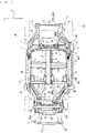
FIG. 1 is a plan view illustrating a main portion of a vehicle including a side vehicle body structure of the present embodiment. -
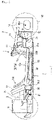
FIG. 2 is a left side view illustrating the main portion of the vehicle including the side vehicle body structure of the present embodiment. -
FIG. 3 is a plan view illustrating a main portion of the side vehicle body structure of the present embodiment. -
FIG. 4(a) is a left side view illustrating the main portion of the side vehicle body structure of the present embodiment, and -
FIG. 4(b) is a left side view illustrated with an exhaust system member removed fromFIG. 4(a) . -
FIG. 5 is an arrow cross-sectional view taken along A-A inFIG. 4 (a) . - An embodiment of the present invention will be explained with reference to the following drawings.
- A vehicle of the present embodiment is a sports car adopting a so-called space frame structure coupling a plurality of extruded frames made of an aluminum alloy and forming a vehicle body framework, and adopting a center pillar-less structure in which a side door is of a two-door type. A side vehicle body structure of such a vehicle will be explained with reference to
FIGs. 1 to 5 . - Furthermore, in order to clarify illustration, in the figures, illustration of a front suspension and a rear suspension is omitted, and detailed illustration of a suspension support member supporting these suspensions, which will be described later, is omitted.
- Furthermore, in the figures, arrow F indicates the vehicle front direction; arrow R, the vehicle right direction; arrow L, the vehicle left direction; arrow U, the vehicle upper direction.
- As illustrated in
FIGs. 1 and2 , the vehicle including the side vehicle body structure of the present embodiment includes avehicle cabin 1 for an occupant to get in, afront vehicle body 2 provided on the vehicle front side relative to thevehicle cabin 1, and a rear vehicle body 3 provided on the vehicle rear side relative to thevehicle cabin 1. - As illustrated in
FIG. 1 , thevehicle cabin 1 and thefront vehicle body 2 are partitioned by a dash panel 9 in a raised wall shape. Namely, the dash panel 9 serves as a partition wall defining a front edge of avehicle cabin space 1s provided inside thevehicle cabin 1 and is disposed between thevehicle cabin 1 and thefront vehicle body 2. - As illustrated in
FIG. 1 , thevehicle cabin 1 includes a floor panel 4 forming a floor (floor surface) of thevehicle cabin 1, a tunnel frame 5 extending in the vehicle front-rear direction above a center position of the floor panel 4 in the vehicle width direction, a tunnel side frame 6 extending in the vehicle front-rear direction at a corner between a side wall on each of both sides of the tunnel frame 5 and the floor panel 4, and a plurality of floor cross members 7 each coupling the tunnel frame 5 and aside sill 8 in the vehicle width direction. - Furthermore, as illustrated in
FIGs. 1 and2 , both sides of the floor panel 4 of thevehicle cabin 1 in the vehicle width direction include the pair of left andright side sills 8 extending in the vehicle front-rear direction, hinge pillars 11 (front-side pillars) each extending upward from a front end of theside sill 8, and rear pillars 12 (rear-side pillars) each extending upward from a rear end of theside sill 8. - Furthermore, as illustrated in
FIG. 2 , on the above-described both sides of thevehicle cabin 1,door openings 13 through which the occupant enters and exits thevehicle cabin 1 are provided. Ahinge pillar 11, arear pillar 12, and theside sill 8 are provided along afront edge 13a,rear edge 13b, andlower edge 13c of the door opening 13, respectively. - As illustrated in
FIGs. 1 and2 , thefront vehicle body 2 includes a pair of left and right frontsuspension support members 14 supporting a front suspension (illustration omitted), a plurality of front-side cross members 15 (seeFIG. 1 ) each coupling the pair of left and right frontsuspension support members 14 in the vehicle width direction, a plurality of front-side coupling frames 16 each coupling thevehicle cabin 1 and the frontsuspension support member 14, and a front shock absorption structure (illustration omitted) that absorbs a shock load from the vehicle front side. - As illustrated in
FIG. 1 , the frontsuspension support member 14 is located on the vehicle-width-direction inner side of theside sill 8 corresponding to each of the left and right sides and pivotally supports a front wheel Hf via the front suspension, which is not illustrated. The front wheel Hf is provided on the vehicle front side relative to the front end of theside sill 8 and on the vehicle-width-direction outer side relative to the frontsuspension support member 14. The frontsuspension support member 14 is manufactured by, for example, die cast molding of an aluminum alloy. - Furthermore, as illustrated in
FIGs. 1 and2 , thefront vehicle body 2 includes, at a position spaced apart rearward from the front wheel Hf, atire stopper frame 17 extending toward the vehicle front side from a front portion of thehinge pillar 11. - Although illustration is omitted, the front shock absorption structure includes a crash can formed of, for example, a cylindrical body extending in the vehicle front-rear direction from the front end side of the front
suspension support member 14, and a bumper reinforcement extending in the vehicle width direction so as to couple front ends of the pair of left and right crash cans. - The rear vehicle body 3 includes a pair of left and right rear
suspension support members 18 supporting a rear suspension, a plurality of rear-side cross members 19 (seeFIG. 1 ) each coupling the pair of left and right rearsuspension support members 18 in the vehicle width direction, a plurality of rear-side coupling frames 21 each coupling thevehicle cabin 1 and the rearsuspension support member 18, and a rearshock absorption structure 22 that absorbs a shock load from the vehicle rear side.
Illustration of not only the above-described front shock absorption structure but also the rearshock absorption structure 22 is omitted inFIG. 2 . - As illustrated in
FIG. 1 , the rearshock absorption structure 22 includes a crash can 22a formed of, for example, a cylindrical body extending toward the vehicle rear side from the rear end side of the rearsuspension support member 18, and abumper reinforcement 22b extending in the vehicle width direction so as to couple rear ends of the pair of left andright crash cans 22a. - Meanwhile, as illustrated in
FIG. 1 , in a front portion of the vehicle of the present embodiment, an area between the pair of left and right frontsuspension support members 14 is formed as an engine room E, and the engine room E is equipped with anengine 23. - An exhaust apparatus 30 (exhaust unit) is connected to an exhaust port provided on the side wall side of this
engine 23, via anexhaust manifold 24. - The
exhaust apparatus 30 includes, as exhaust system members, a GPF 31 (gasoline particulate filter), afirst pre-silencer 32, asecond pre-silencer 33, amain silencer 34, and a tail pipe (illustration omitted). Furthermore, theexhaust manifold 24 and theGPF 31 are connected by aconnection part 35A, the above-describedexhaust system members connection part 35B, the above-describedexhaust system members connection part 35C, and the above-describedexhaust system members connection part 35D. - The
GPF 31 has abody 31a including a filter 31aa that, as an exhaust treatment device that treats exhaust gas of theengine 23, collects a particulate matter (PM) included in the exhaust gas. - Each of the silencers (the
first pre-silencer 32, thesecond pre-silencer 33, and the main silencer 34) reduces a sound when the exhaust gas is released to the atmosphere. - Although the
connection parts exhaust pipe 35a, theconnection parts GPF 31, thesilencers exhaust pipe 35a and connection portions having a function of connecting to the otherexhaust system members connection parts exhaust pipe 35a and the connection portion provided in the exhaust system member, can be formed by at least one of these. - In the
exhaust apparatus 30, theGPF 31, thefirst pre-silencer 32, thesecond pre-silencer 33, and themain silencer 34 are each routed along an exhaust path extending rearward from the front side of the vehicle body via the connection part. - Note that in this example, the
exhaust apparatus 30 is routed along an exhaust path such that the exhaust path bypasses the vehicle-width-direction outer side (the vehicle right side, in this example) in the middle of extending toward the vehicle rear side. Specifically, theexhaust apparatus 30 is routed in thefront vehicle body 2 from, in the vehicle width direction, the inner side equipped with theengine 23 toward the outer side and routed toward the vehicle rear side along a side portion of thevehicle cabin 1, and theexhaust apparatus 30 is routed again in the rear vehicle body 3 from the vehicle-width-direction outer side toward the inner side and routed toward the vehicle rear side. - Thus, the exhaust system member, which is relatively light, is laid out on the vehicle-width-direction outer side, so that a heavy object can be laid out at the vehicle center relative to the exhaust system member, consequently contributing to enhancement of a motion performance of the vehicle.
- Hereinafter, the vehicle body side structure of the present embodiment will be explained in more detail with reference to
FIGs. 3 to 5 . - As illustrated in
FIGs. 4(b) and5 , theside sill 8 is configured with a two-divided structure including a side sill upper 81 and a side sill lower 82 on the upper and lower sides. The side sill upper 81 and the side sill lower 82 are both frame members each formed by extrusion of an aluminum alloy material as described above, and respectively have closedcross-sectional spaces FIG. 5 ) inside which extend over the full length in the vehicle front-rear direction. - The side sill upper 81 is formed by integrating a closed cross-section portion 83 (hereinafter also referred to as the "upper-side closed
cross-section portion 83") having the closed cross-sectional space 83a inside, and alower flange 85 extending downward from a vehicle-width-direction inner end of the upper-side closedcross-section portion 83 and a lower end thereof. - Furthermore, as illustrated in the same figure, the side sill lower 82 is formed by integrating a closed cross-section portion 84 (hereinafter also referred to as the "lower-side closed
cross-section portion 84") having the closedcross-sectional space 84s inside, and anupper flange 86 extending upward from the vehicle-width-direction inner side of the lower-side closedcross-section portion 84 and an upper end thereof. - As illustrated in
FIG. 4(b) , the upper-side closedcross-section portion 83 and the lower-side closedcross-section portion 84 both extend in the vehicle front-rear direction so as to overlap with thepillars side sill 8 in the vehicle front-rear direction. - Furthermore, as illustrated in
FIGs. 3 and5 , the upper-side closedcross-section portion 83 and the lower-side closedcross-section portion 84 are both formed to be longer in the vehicle width direction than thepillars cross-section portion 83 and the lower-side closedcross-section portion 84 in the present embodiment are both formed so that outer ends thereof in the vehicle width direction project toward the vehicle-width-direction outer side relative to vehicle-width-direction outer faces of thepillars - Furthermore, as illustrated in
FIG. 5 , anupper wall 83u andlower wall 83d of the upper-side closedcross-section portion 83 are both formed inclinedly so as to be located upward toward the vehicle-width-direction outer side and extend parallel to each other in the vehicle front-rear direction. - Note that as illustrated in
FIGs. 3 and5 , in theupper wall 83u, an outer-side portion in the vehicle width direction relative to thepillars lower wall 83d in the vehicle up-down direction decreases stepwise. Namely, the upper-side closedcross-section portion 83 is formed in a tapered shape in which the outer side in the vehicle width direction becomes gradually narrower in the vehicle up-down direction. - As illustrated in
FIG. 5 , on the vehicle-width-direction outer side relative to the upper-side closedcross-section portion 83 of the side sill upper 81, aneaves 87 is provided which extends in a flange shape outward in the vehicle width direction and downward from a vehicle-width-direction outer end of the upper-side closedcross-section portion 83 and covers thefirst pre-silencer 32 as an exhaust system member, which will be described later, from above. - Furthermore, as illustrated in
FIG. 5 , alower wall 84d of the lower-side closedcross-section portion 84 is substantially horizontally formed along the vehicle width direction, while anupper wall 84u is moderately inclined so as to be located downward toward the vehicle-width-direction outer side. Thereby, the lower-side closedcross-section portion 84 is formed in a substantially triangular shape in which a cross section orthogonal to the vehicle front-rear direction becomes longer in the vehicle width direction than in the vehicle up-down direction and the length in the vehicle up-down direction becomes shorter toward the vehicle-width-direction outer side. - As illustrated in
FIGs. 4(b) and5 , in the above-described side sill upper 81 and side sill lower 82, thelower flange 85 and theupper flange 86 overlap with each other in a vehicle side view (in the vehicle up-down direction and the vehicle front-rear direction). In this example, as illustrated inFIG. 5 , thelower flange 85 of the side sill upper 81 and theupper flange 86 of the side sill lower 82 are disposed in such a manner that thelower flange 85 and theupper flange 86 are respectively located on the vehicle-width-direction outer side and the vehicle-width-direction inner side, in a mutually overlappingportion 93. - The side sill upper 81 and the side sill lower 82 are joined to each other in this overlapping
portion 93 by being arc-welded (MIG welding, in this example) alternately from the vehicle-width-direction inner and outer sides along the vehicle front-rear direction (see reference character w inFIG. 5 ). - As described above, in the
side sill 8, thelower flange 85 and theupper flange 86 can be integrated by welding the mutually overlappingportion 93, forming acoupling wall 90 coupling vehicle-width-direction inner ends of the upper-side closedcross-section portion 83 and the lower-side closedcross-section portion 84 in the up-down direction. - Thereby, the
side sill 8 is configured so that theclosed cross-section portion 83 of the side sill upper 81 and theclosed cross-section portion 84 of the side sill lower 82 are disposed so as to be spaced apart from each other in the up-down direction via thecoupling wall 90 and, between theseclosed cross-section portions coupling wall 90, arecess 91 is provided which opens toward the vehicle-width-direction outer side (seeFIGs. 4(b) and5 ). - As illustrated in
FIG. 2 , theside sill 8 extends in the vehicle front-rear direction so as to form thelower edge 13c of the door opening 13 of a vehicle body side portion, as described above. Furthermore, theside sill 8 extends inclinedly in the vehicle front-rear direction in such a manner that the upper-side closedcross-section portion 83, namely, an upper end of theside sill 8, is located downward toward the front side (seeFIGs. 2 , and4(a) and (b) ). - Thereby, the
lower edge 13c of the door opening 13 can be formed inclinedly so as to be located upward toward the vehicle rear side along the upper-side closed cross-section portion 83 (seeFIG. 2 ). Accordingly, while a careless increase in the size of the door opening 13 over the entire vehicle front-rear direction is suppressed, the vehicle front side can be located downward compared with the vehicle rear side, so that, when the occupant enters and exits the vehicle cabin space via thedoor opening 13, smooth accessibility is enabled. - The above-described
side sill 8 andpillars FIG 4(b) , the upper-side closedcross-section portion 83 and the lower-side closedcross-section portion 84 in the present embodiment both extend in the vehicle front-rear direction so as to overlap with thehinge pillar 11 in the vehicle front-rear direction. In this example, in the upper-side closedcross-section portion 83, a front end extends up to substantially the same position as a front end of thehinge pillar 11 in the vehicle front-rear direction. On the other hand, the lower-side closedcross-section portion 84 includes a front extendingportion 84f extending toward the vehicle front side relative to each of the front ends of the upper-side closedcross-section portion 83 and thehinge pillar 11 in the vehicle front-rear direction, and is integrally formed with the front extendingportion 84f. Note that the front extendingportion 84f extends toward the vehicle front side until a front end thereof is located on the vehicle rear side relative to a front end of thetire stopper frame 17. - Furthermore, as illustrated in
FIGs. 3 and4 , at a front portion of theside sill 8, thehinge pillar 11 is provided to protrude at the lower-side closedcross-section portion 84 in such a manner that thehinge pillar 11 projects toward the vehicle upper side from a vehicle-width-direction inner-side portion of the upper-side closedcross-section portion 83, in a posture inclined so as to be located on the vehicle front side toward the vehicle upper side. Thehinge pillar 11 is an extruded member made of an aluminum alloy which is extruded in a rectangular shape in which a cross section orthogonal to the longitudinal direction inside forms a closed cross-section. - In the
hinge pillar 11 as described above, a portion facing each of the upper-side closedcross-section portion 83, thecoupling wall 90, and the lower-side closedcross-section portion 84 is integrally joined thereto by arc welding or the like. - On the other hand, at a rear portion of the
side sill 8, therear pillar 12 is provided to protrude in a columnar shape at the lower-side closedcross-section portion 84 in such a manner that therear pillar 12 projects toward the vehicle upper side from the vehicle-width-direction inner-side portion of the upper-side closedcross-section portion 83, in a posture inclined so as to be located on the vehicle rear side toward the vehicle upper side. Furthermore, therear pillar 12 is an extruded member made of an aluminum alloy which is extruded in a rectangular shape in which a cross section orthogonal to the longitudinal direction inside forms a closed cross-section. - In the
rear pillar 12 as described above, a portion facing each of the upper-side closedcross-section portion 83, thecoupling wall 90, and the lower-side closedcross-section portion 84 is integrally joined thereto by arc welding or the like. - As illustrated in FIG. 3(b), the above-described
tire stopper frame 17 is also referred to as a reinforcement for small overlap collision resistance (reinforcement for SORB) and is a frame for receiving the front wheel Hf (seeFIGs. 1 and2 ) receding at the time of small overlap collision, and suppressing entering of the front wheel Hf into thevehicle cabin 1. - The
tire stopper frame 17 has a rear end joined to a front face of thehinge pillar 11, and a front end horizontally extending in the vehicle front-rear direction up to a position in front of a rearmost end of the front wheel Hf. Thereby, in thetire stopper frame 17, the front end is disposed at a position spaced apart toward the vehicle rear side from the rearmost end of the front wheel Hf (seeFIGs. 1 and2 ). Furthermore, as illustrated inFIG. 4 , thetire stopper frame 17 is formed by extrusion in such a manner that a cross section thereof which is orthogonal to the vehicle front-rear direction is formed in a closed cross-sectional shape. - Furthermore, as illustrated in
FIGs. 1 and2 , in theexhaust apparatus 30, each of theGPF 31, thefirst pre-silencer 32, and thesecond pre-silencer 33 is disposed in this order toward the vehicle rear side along a lower portion of the vehicle body side portion (a vehicle right-side portion, in this example). - Specifically, the
GPF 31 includes thebody 31a in which the filter 31aa is incorporated, and aconnection portion 31b formed to have a smaller width than thebody 31a. In theGPF 31, thebody 31a is mainly disposed, in a vehicle body lower portion, on the vehicle front side relative to thehinge pillar 11 and on the vehicle-width-direction outer side relative to thetire stopper frame 17. - Furthermore, the above-described
front extending portion 84f provided at a front portion of the lower-side closedcross-section portion 84 of theside sill 8 extends up to immediately under theGPF 31 disposed on the vehicle-width-direction outer side relative to thetire stopper frame 17. TheGPF 31 is supported so as to be placed on a top face of the front extendingportion 84f. - The
body 31a of theGPF 31 and the engine 23 (exhaust manifold 24) provided on the vehicle-width-direction inner side relative to thebody 31a are connected by theconnection part 35A (hereinafter referred to as the "first connection part 35A") extending in the vehicle width direction between these. - The
first connection part 35A is formed by theexhaust pipe 35a provided as a part of theexhaust apparatus 30. Furthermore, in a vehicle plan view, thetire stopper frame 17 intervenes between theGPF 31 and theengine 23, while thefirst connection part 35A extends in the vehicle width direction across a space Sd (seeFIG. 4(b) ) provided below thetire stopper frame 17. - As illustrated in
FIGs. 2 and4(a) , thefirst pre-silencer 32 is formed to have a long length in the vehicle front-rear direction along theside sill 8 provided at thelower edge 13c of thedoor opening 13. Thefirst pre-silencer 32 is formed to have substantially a constant length in the vehicle width direction over the full length in the vehicle front-rear direction and formed in a vehicle side view shape in which thefirst pre-silencer 32 is inclined so as to become gradually higher toward the vehicle rear side. - On the other hand, the
recess 91 is formed to have a length in the vehicle front-rear direction which is slightly longer than that of thefirst pre-silencer 32 in the vehicle front-rear direction. Furthermore, therecess 91 has a length in the vehicle up-down direction which is slightly longer than that of thefirst pre-silencer 32 in the vehicle up-down direction, and is formed in an inclined shape so as to become gradually higher toward the vehicle rear side corresponding to the above-described vehicle side view shape of thefirst pre-silencer 32. - As illustrated in
FIGs. 3 and5 , thefirst pre-silencer 32 is disposed on the vehicle-width-direction outer side relative to a vehicle-width-direction inner end of theside sill 8 in such a manner that at least a part of thefirst pre-silencer 32 in the vehicle width direction overlaps with theside sill 8. Namely, the entire first pre-silencer 32 except for an outer-side portion thereof in the vehicle width direction is accommodated in therecess 91 of theside sill 8 over the full length of the vehicle front-rear direction (seeFIG. 3 ). - Here, although in this example, an embodiment will be explained in which the
first pre-silencer 32 is accommodated in therecess 91 of theside sill 8, an exhaust system member other than thefirst pre-silencer 32 may be accommodated therein. - Furthermore, the accommodation of the exhaust system member in the
recess 91 also includes a case where, not limited to the entire exhaust system member in the vehicle width direction, at least a part of the exhaust system member in the vehicle width direction is disposed on the vehicle-width-direction inner side relative to a position on the outermost side of theside sill 8 in the vehicle width direction. - Namely, the accommodation of the exhaust system member in the
recess 91 also includes a case where, not limited to the entire exhaust system member in the vehicle width direction, at least a part thereof overlaps in the vehicle width direction with a portion of theside sill 8 corresponding to therecess 91 in the vehicle width direction. - Furthermore, the overlapping of at least a part of the exhaust system member in the vehicle width direction may have an overlapping amount in which the occupant is less likely to feel heat at the time of entering and exiting the vehicle astride the
side sill 8. Specifically, when explanation is made by taking a case as an example in which, as the exhaust system member, thefirst pre-silencer 32 is accommodated in therecess 91 as in this example, a length (Wr) of thefirst pre-silencer 32 at a portion of the side sill corresponding to therecess 91 in the vehicle width direction is desirably equal to or more than 50% of a length (Wo) of thefirst pre-silencer 32 in the vehicle width direction, as illustrated inFIG. 5 . - In this accommodation state, a vehicle-width-direction inner end of the
first pre-silencer 32 is disposed on the vehicle-width-direction outer side relative to the coupling wall 90 (vehicle width inner wall) of theside sill 8, and thefirst pre-silencer 32 is supported so as to be placed on a top face of the lower-side closedcross-section portion 84. - In this state, the
first pre-silencer 32 is disposed so as to overlap with theeaves 87 and the upper-side closedcross-section portion 83 which are provided in the side sill upper 81, in the vehicle width direction.
Namely, theeaves 87 and the upper-side closedcross-section portion 83 in theside sill 8 are provided so as to cover the first pre-silencer 32 from immediately thereabove. - Furthermore, as illustrated in
FIGs. 3 and4(a) , theGPF 31 disposed on the vehicle front side of thehinge pillar 11 and thefirst pre-silencer 32 disposed on the vehicle rear side thereof are connected by theconnection part 35B (hereinafter referred to as the "second connection part 35B"). - The
second connection part 35B is formed by theexhaust pipe 35a and theconnection portion 31b provided in theGPF 31. Theconnection portion 31b provided in theGPF 31 is formed in a pipe shape extending toward the vehicle rear side from a rear end of thebody 31a of theGPF 31 and is connected to theexhaust pipe 35a so as to fit theexhaust pipe 35a from a front portion thereof. - As illustrated in
FIG. 3 , thesecond connection part 35B is formed to have a smaller length in the vehicle width direction than both theGPF 31 and thefirst pre-silencer 32. Furthermore, thesecond connection part 35B substantially horizontally extends at a position on the vehicle-width-direction outer side as close as possible to thehinge pillar 11 astride thehinge pillar 11 in the vehicle front-rear direction. Furthermore, thesecond connection part 35B is formed to have a length which is longer than that of thehinge pillar 11 in the vehicle front-rear direction so as to be capable of connecting theGPF 31 disposed on the vehicle front side of thehinge pillar 11 and thefirst pre-silencer 32 disposed on the vehicle rear side of thehinge pillar 11. - As described above, in a state where, while the
exhaust pipe 35a is disposed near thehinge pillar 11 side as much as possible (on the vehicle-width-direction inner side), theGPF 31, theexhaust pipe 35a, and thefirst pre-silencer 32 are disposed in substantially a linear shape along the vehicle front-rear direction, in thefirst pre-silencer 32, at least a vehicle-width-direction inner-side portion relative to a vehicle-width-direction outer face of thehinge pillar 11 is accommodated in therecess 91 of theside sill 8, while the GPF 31 (thebody 31a of theGPF 31, in particular) is disposed on the vehicle-width-direction outer side relative to thetire stopper frame 17, as described above. - Furthermore, as described above, in the side sill upper 81 of the
side sill 8, namely, in theeaves 87 and the upper-side closedcross-section portion 83, each of front ends is formed up to substantially the same position as the front end of thehinge pillar 11 in the vehicle front-rear direction (seeFIGs. 2 and4(a) and (b) ). - Thus, so as to cover not only the
first pre-silencer 32 but also thesecond connection part 35B disposed on the vehicle-width-direction outer side of thehinge pillar 11 from the vehicle upper side, theeaves 87 and the upper-side closedcross-section portion 83 are each provided at a position spaced apart upward from thesecond connection part 35B. - Furthermore, as illustrated in
FIGs. 3 and4(a) , thesecond pre-silencer 33 is disposed at a portion going around, with respect to therear pillar 12, from forward to rearward and from the outer side to the inner side in the vehicle width direction. - The
second pre-silencer 33 as described above is connected to theconnection part 35C (also referred to as the "third connection part 35C") connecting to thefirst pre-silencer 32 provided on the vehicle front side at a front end portion of thebody 33a, and is connected to theconnection part 35D (also referred to as the "fourth connection part 35D") connecting to the main silencer 34 (seeFIG. 1 ) provided at the vehicle-width-direction center and on the vehicle rear side, on the vehicle-width-direction inner side of thebody 33a and at a vehicle rear portion. - As illustrated in
FIGs. 1 and2 , the above-described side vehicle body structure of the vehicle in the present embodiment is a side vehicle body structure of a vehicle which includes the engine 23 (internal combustion engine) (seeFIG. 1 ) equipped on the front side of the dash panel 9 (partition wall) defining the front edge of thevehicle cabin space 1s, theexhaust apparatus 30 through which exhaust gas exhausted from theengine 23 passes, and theside sill 8 extending along the vehicle front-rear direction on the side of the floor panel (floor) forming the floor surface of thevehicle cabin space 1s, wherein, as illustrated inFIGs. 4(b) and5 , theside sill 8 has arecess 91 having a cross section recessed toward the vehicle-width-direction inner side from the vehicle-width-direction outer side in a cross-sectional view orthogonal to the vehicle front-rear direction and extending in the vehicle front-rear direction, and, as illustrated inFIGs. 1 to 3 ,4(a), and5 , the first pre-silencer 32 (the exhaust system member provided in the exhaust apparatus) provided in theexhaust apparatus 30 is disposed at therecess 91. - According to the configuration, even in a case where a vehicle-width-direction inner end of the
first pre-silencer 32 is provided on the vehicle-width-direction outer side relative to the vehicle-width-direction inner end of theside sill 8, at least a part of thefirst pre-silencer 32 in the vehicle width direction can be located in therecess 91, so that widening of the vehicle can be suppressed. - Accordingly, while, with widening of the vehicle suppressed, the
first pre-silencer 32, which is light, can be laid out on the vehicle-width-direction outer side, so that the heavy object can be laid out at the vehicle center, thus contributing to enhancement of the motion performance of the vehicle consequently. - In an aspect of the present invention, as illustrated in
FIGs. 3 and4(a) , it is characterized in that theexhaust apparatus 30 has theexhaust pipe 35a and theexhaust system members exhaust system members exhaust pipe 35a, and are disposed at therecess 91 in such a manner that the passing direction is substantially parallel to the longitudinal direction of theside sill 8. - According to the configuration, the
exhaust system members exhaust pipe 35a are disposed at therecess 91 in such a manner that the passing direction is substantially parallel to the longitudinal direction of theside sill 8, so that, in such a case where theexhaust system members - In an aspect of the present invention, as illustrated in
FIG. 2 , the door opening 13 (opening) through which the occupant enters and exits the vehicle cabin space of thevehicle cabin 1 is formed above theside sill 8, and, as illustrated inFIG. 5 , theside sill 8 has the side sill upper 81 overlapping with thefirst pre-silencer 32 in the vehicle width direction on the upper side relative to thefirst pre-silencer 32. - According to the configuration, when the occupant enters and exits the vehicle cabin space of the
vehicle cabin 1 through thedoor opening 13, heat damage to the occupant due to heat release from thefirst pre-silencer 32 can be suppressed. - Specifically, in a case where, for enhancement of the motion performance of the vehicle, the
first pre-silencer 32 is provided adjacent to the vehicle-width-direction outer side of theside sill 8, when the occupant enters and exits the vehicle cabin space of thevehicle cabin 1 through thedoor opening 13, there is a concern about heat damage in which, for example, the occupant feels heat due to heat released from thefirst pre-silencer 32. - In contrast, in the present embodiment, the
first pre-silencer 32 can be covered from above by the side sill upper 81 as an upper side portion of therecess 91, and the side sill upper 81 can function as a heat shielding member against the heat release from thefirst pre-silencer 32. - Accordingly, when the occupant enters and exits the vehicle cabin space of the
vehicle cabin 1 through thedoor opening 13, the heat damage to the occupant due to the heat release from thefirst pre-silencer 32 can be suppressed. - In an aspect of the present invention, as illustrated in
FIG. 5 , the side sill upper 81 includes the upper-side closedcross-section portion 83 having the closedcross-sectional space 83s inside. - According to the configuration, the closed
cross-sectional space 83s provided inside the upper-side closedcross-section portion 83 in the side sill upper 81 can make the occupant even less likely to feel heat when the occupant enters and exits the vehicle cabin space of thevehicle cabin 1. - In an aspect of the present invention, as illustrated in
FIG. 5 , on the vehicle-width-direction outer end of the upper-side closedcross-section portion 83 of the side sill upper 81, theeaves 87 is provided which extends outward in the vehicle width direction and downward from the vehicle-width-direction outer end and covers the first pre-silencer 32 from above. - According to the configuration, the
eaves 87 extends not only outward in the vehicle width direction but also downward from the vehicle-width-direction outer side of the side sill upper 81, so that, while an amount of shielding of heat released upward from thefirst pre-silencer 32 is more enhanced, the shielding range can be more expanded. - Accordingly, it is possible to make the occupant even less likely to feel heat when the occupant enters and exits the vehicle cabin space of the
vehicle cabin 1. - In an aspect of the present invention, as illustrated in
FIGs. 2 and4(a) , thefirst pre-silencer 32 is formed to have the long length in the vehicle front-rear direction along thelower edge 13c of thedoor opening 13 and is formed so as to be higher on the rear side than on the front side in the vehicle front-rear direction, and the side sill upper 81 is formed so as to be higher on the rear side than on the front side in the vehicle front-rear direction corresponding to the vehicle side view shape of thefirst pre-silencer 32. - According to the configuration, the side sill upper 81 is formed so as to be higher on the rear side than on the front side, so that the
lower edge 13c (seeFIG. 2 ) of the door opening 13 can be formed in such a manner that a front-side portion thereof becomes lower than a rear-side portion thereof. Accordingly, it is possible for the occupant to smoothly enter and exit the vehicle cabin space of thevehicle cabin 1 through thedoor opening 13. - On the other hand, for example, in a case where a gap (space) open toward the vehicle-width-direction outer side is formed between the
first pre-silencer 32 and the side sill upper 81 covering the first pre-silencer 32 from above, there is a concern that heat released from thefirst pre-silencer 32 diffuses toward the vehicle upper side from the vehicle-width-direction outer side through the gap and the occupant may be damaged by the heat. - In contrast, as described above, the side sill upper 81 is formed corresponding to the vehicle side view shape of the
first pre-silencer 32, so that thefirst pre-silencer 32 disposed at therecess 91 can be firmly covered from above by the side sill upper 81. Thus, theside sill 8 can effectively function as a heat shielding member against the heat release from thefirst pre-silencer 32. - The present invention is not limited to only the configurations of the above-described embodiment and can be formed in various embodiments. For example, although in the above-described embodiment, the embodiment has been explained in which the
first pre-silencer 32 is disposed at therecess 91 of theside sill 8, the present invention is not limited to this embodiment, and the otherexhaust system members exhaust pipe 35a may be disposed at therecess 91 of theside sill 8. - Even in a case where only the
exhaust pipe 35a is accommodated (disposed) in therecess 91, a configuration may be used in which, similarly to the exhaust system member such as thefirst pre-silencer 32, not limited to the entire width direction of theexhaust pipe 35a, at least a part thereof is accommodated in therecess 91. -
- 1s vehicle cabin space
- 4 floor panel (floor)
- 8 side sill
- 9 dash panel (partition wall)
- 13 door opening (opening)
- 13c lower edge of door opening (lower edge of opening)
- 23 engine (internal combustion engine)
- 30 exhaust apparatus
- 32 first pre-silencer (exhaust system member)
- 81 side sill upper (side sill upper portion)
- 83s closed cross-sectional space (closed cross-sectional space provided inside side sill upper portion)
- 87 eaves
- 91 recess
Claims (12)
- A vehicle comprising:an internal combustion engine (23) equipped on a front side of a partition wall (9) defining a front edge of a vehicle cabin space (1s);an exhaust apparatus (30) through which exhaust gas exhausted from the internal combustion engine (23) passes; anda side sill (8) extending along a vehicle front-rear direction on a side of a floor (4) forming a floor surface of the vehicle cabin space (1s),characterized in that the side sill (8) comprises a recess (91) having a cross section recessed toward a vehicle-width-direction inner side from a vehicle-width-direction outer side in a cross-sectional view orthogonal to the vehicle front-rear direction and extending in the vehicle front-rear direction, andthe exhaust apparatus (30) is disposed at the recess (91).
- The vehicle according to claim 1, characterized in thatthe exhaust apparatus (30) comprises an exhaust pipe (35a) and an exhaust system member (32), andthe exhaust system member (32) has a larger cross-sectional area orthogonal to a passing direction of exhaust gas than the exhaust pipe (35a), and is disposed at the recess (91) in such a manner that the passing direction is parallel to a longitudinal direction of the side sill (8).
- The vehicle according to claim 2,
wherein the system member (32) is a particulate filter, a silencer or a catalyzer. - The vehicle according to claim 2 or 3,wherein an opening (13) through which an occupant enters and exits the vehicle cabin space (1s) is formed above the side sill (8), andthe side sill (8) comprises a side sill upper portion (81) overlapping with the exhaust system member (32) in a vehicle width direction on an upper side relative to the exhaust system member (32).
- The vehicle according to claim 4,
wherein the side sill upper portion (81) is a closed cross-sectional structure comprising a closed cross-sectional space (83s) inside. - The vehicle according to any preceding claim,
wherein the side sill (8) is configured with a two-divided structure including a side sill upper portion (81) and a side sill lower portion (82) on the upper and lower sides. - The vehicle according to claim 6,
wherein the side sill upper portion (81) and the side sill lower portion (82) are both frame members formed by extrusion and having closed cross-sectional spaces (83s) and (84s) inside, which extend over the full length in the vehicle front-rear direction. - The vehicle according to any one of claims 4 to 7,
wherein, on a vehicle-width-direction outer side of the side sill upper portion (81), an eaves (87) is provided, the eaves (87) extending outward in the vehicle width direction and downward and covering the exhaust system member (32) from above. - The vehicle according to any one of claims 4 to 8,wherein the exhaust system member (32) is extended in the vehicle front-rear direction along a lower edge of the opening (13) and is higher in the vehicle up-down direction on a rear side than on a front side in the vehicle front-rear direction, andthe side sill upper portion (81) is higher in the vehicle up-down direction on a rear side than on a front side in the vehicle front-rear direction, such that the side sill upper portion (81) and the exhaust system member (32) have corresponding shapes from a vehicle side view.
- The vehicle according to any preceding claim,
further comprising front-side pillars (11) each extending upward from a front end of the side sill (8), and rear pillars (12) each extending upward from a rear end of the side sill (8). - The vehicle according to any preceding claim comprising a vehicle cabin (1) and a side vehicle body structure.
- The vehicle of claim 11,
wherein the exhaust apparatus (30) is routed from, in the vehicle width direction, the inner side equipped with the engine (23) toward the outer side and routed toward the vehicle rear side along in the side vehicle body structure, and the exhaust apparatus (30) is routed again from the vehicle-width-direction outer side toward the inner side and routed toward the vehicle rear side.
Applications Claiming Priority (1)
| Application Number | Priority Date | Filing Date | Title |
|---|---|---|---|
| JP2020038728A JP7375618B2 (en) | 2020-03-06 | 2020-03-06 | Vehicle side body structure |
Publications (2)
| Publication Number | Publication Date |
|---|---|
| EP3875298A1 EP3875298A1 (en) | 2021-09-08 |
| EP3875298B1 true EP3875298B1 (en) | 2022-11-09 |
Family
ID=74672071
Family Applications (1)
| Application Number | Title | Priority Date | Filing Date |
|---|---|---|---|
| EP21157980.0A Active EP3875298B1 (en) | 2020-03-06 | 2021-02-18 | Side vehicle body structure of vehicle |
Country Status (4)
| Country | Link |
|---|---|
| US (1) | US11571965B2 (en) |
| EP (1) | EP3875298B1 (en) |
| JP (1) | JP7375618B2 (en) |
| CN (1) | CN113353158B (en) |
Families Citing this family (1)
| Publication number | Priority date | Publication date | Assignee | Title |
|---|---|---|---|---|
| JP7359043B2 (en) * | 2020-03-06 | 2023-10-11 | マツダ株式会社 | Vehicle side body structure |
Family Cites Families (31)
| Publication number | Priority date | Publication date | Assignee | Title |
|---|---|---|---|---|
| DE743439C (en) * | 1940-01-20 | 1943-12-27 | Friedrich Maier Dipl Ing | Motor vehicle with a muffler arranged above the car floor level |
| US2875841A (en) * | 1955-01-19 | 1959-03-03 | Gen Motors Corp | Motor vehicle construction |
| US3177031A (en) * | 1959-08-17 | 1965-04-06 | Smith Corp A O | Motor vehicle having increased ground clearance level floor space |
| US3495673A (en) * | 1967-08-09 | 1970-02-17 | Diran Yazejian | Vehicle body accessory |
| US4493506A (en) * | 1982-03-29 | 1985-01-15 | American Sunroof Corporation | Vehicle rocker panel structure |
| US5042870A (en) * | 1986-11-02 | 1991-08-27 | Yamaha Hatsudoki Kabushiki Kaisha | Motor vehicle |
| JPS63166830U (en) * | 1987-04-20 | 1988-10-31 | ||
| JPH02120267U (en) * | 1989-03-15 | 1990-09-27 | ||
| JPH0459513U (en) * | 1990-09-29 | 1992-05-21 | ||
| USD360171S (en) * | 1993-03-31 | 1995-07-11 | Chrysler Corporation | Automobile |
| US5388408A (en) * | 1993-10-01 | 1995-02-14 | Lawrence-Keech Inc. | Exhaust system for internal combustion engines |
| US6141958A (en) * | 1998-12-31 | 2000-11-07 | Voss; Randy E. | Exhaust cooling system for vehicles |
| JP2001115835A (en) * | 1999-10-18 | 2001-04-24 | Mazda Motor Corp | Pipe arranging structure for vehicle |
| USD430508S (en) * | 1999-10-29 | 2000-09-05 | Daimlerchrysler Corporation | Automobile body |
| USD456313S1 (en) * | 2000-12-27 | 2002-04-30 | Daimlerchrysler Corporation | Automobile body |
| JP3788780B2 (en) * | 2002-11-19 | 2006-06-21 | 本田技研工業株式会社 | Arrangement structure of vehicle canister |
| JP2005178649A (en) * | 2003-12-22 | 2005-07-07 | Toyota Motor Corp | Substructure of vehicle body |
| JP2006298145A (en) * | 2005-04-20 | 2006-11-02 | Nissan Motor Co Ltd | Vehicle floor structure |
| JP4935363B2 (en) * | 2007-01-09 | 2012-05-23 | マツダ株式会社 | Front body structure of automobile |
| DE102009008799A1 (en) * | 2009-02-05 | 2010-09-16 | Deutsches Zentrum für Luft- und Raumfahrt e.V. | Motor vehicle comprises exhaust emitting drive unit, and exhaust system, which has exhaust after treatment unit, where exhaust after treatment unit is integrated in sections into support structure of body of motor vehicle |
| JP5358284B2 (en) * | 2009-05-14 | 2013-12-04 | 本田技研工業株式会社 | Lower body floor structure |
| USD687349S1 (en) * | 2012-03-06 | 2013-08-06 | Chrysler Group Llc | Automobile body |
| BR112014029810B1 (en) * | 2012-06-04 | 2022-04-19 | Honda Motor Co., Ltd. | vehicle body structure |
| JP5929609B2 (en) * | 2012-08-07 | 2016-06-08 | スズキ株式会社 | In-vehicle structure of battery pack |
| JP6060864B2 (en) * | 2013-09-18 | 2017-01-18 | マツダ株式会社 | Storage device arrangement structure |
| JP6596752B2 (en) * | 2016-06-24 | 2019-10-30 | 本田技研工業株式会社 | Lower body structure |
| JP6642346B2 (en) | 2016-09-09 | 2020-02-05 | トヨタ自動車株式会社 | Vehicle undercarriage |
| JP2020026159A (en) * | 2018-08-09 | 2020-02-20 | トヨタ自動車株式会社 | Vehicle lower part structure |
| DE102018213673B4 (en) * | 2018-08-14 | 2023-03-16 | Audi Ag | Side skirts for an automobile and motor vehicle |
| JP7359043B2 (en) * | 2020-03-06 | 2023-10-11 | マツダ株式会社 | Vehicle side body structure |
| JP7264091B2 (en) * | 2020-03-06 | 2023-04-25 | マツダ株式会社 | Vehicle side body structure |
-
2020
- 2020-03-06 JP JP2020038728A patent/JP7375618B2/en active Active
-
2021
- 2021-01-04 CN CN202110000990.9A patent/CN113353158B/en active Active
- 2021-02-17 US US17/177,903 patent/US11571965B2/en active Active
- 2021-02-18 EP EP21157980.0A patent/EP3875298B1/en active Active
Also Published As
| Publication number | Publication date |
|---|---|
| US20210276413A1 (en) | 2021-09-09 |
| JP2021138300A (en) | 2021-09-16 |
| JP7375618B2 (en) | 2023-11-08 |
| US11571965B2 (en) | 2023-02-07 |
| CN113353158B (en) | 2023-04-21 |
| CN113353158A (en) | 2021-09-07 |
| EP3875298A1 (en) | 2021-09-08 |
Similar Documents
| Publication | Publication Date | Title |
|---|---|---|
| US11524727B2 (en) | Side vehicle body structure of vehicle | |
| US11518445B2 (en) | Side vehicle body structure of vehicle | |
| US11548565B2 (en) | Side vehicle body structure of vehicle | |
| US20230095674A1 (en) | Vehicle-body structure with improved passenger comfort and vehicle-body stiffness | |
| JP2005067491A (en) | Vehicle body structure | |
| EP2559611B1 (en) | Structure of front section of vehicle body | |
| JP4701916B2 (en) | Car battery mounting structure | |
| WO2016072287A1 (en) | Vehicle | |
| US20230101665A1 (en) | Vehicle-body structure with a battery cover for improved aerodynamic performance | |
| EP3875298B1 (en) | Side vehicle body structure of vehicle | |
| CN109204575B (en) | Vehicle body structure and vehicle | |
| JP4342189B2 (en) | Auto body front structure | |
| JP4756332B2 (en) | Car battery mounting structure | |
| CN113212563B (en) | Vehicle structure | |
| US10569805B2 (en) | Frame assembly for a vehicle and vehicle having same | |
| JP4140272B2 (en) | Arrangement structure in engine room of vehicle | |
| JP5807533B2 (en) | Vehicle floor structure | |
| JP2005225414A (en) | Fuel tank mounting structure of vehicle | |
| JP3461723B2 (en) | Car body frame structure | |
| JP2008037305A (en) | Vehicle body structure | |
| JP5556715B2 (en) | vehicle | |
| JP2023051654A (en) | Vehicle body structure | |
| JP2022184363A (en) | Vehicle lower part structure | |
| JPH11245855A (en) | Body structure of vehicle | |
| JP2020189578A (en) | Vehicle front part structure |
Legal Events
| Date | Code | Title | Description |
|---|---|---|---|
| PUAI | Public reference made under article 153(3) epc to a published international application that has entered the european phase |
Free format text: ORIGINAL CODE: 0009012 |
|
| STAA | Information on the status of an ep patent application or granted ep patent |
Free format text: STATUS: THE APPLICATION HAS BEEN PUBLISHED |
|
| AK | Designated contracting states |
Kind code of ref document: A1 Designated state(s): AL AT BE BG CH CY CZ DE DK EE ES FI FR GB GR HR HU IE IS IT LI LT LU LV MC MK MT NL NO PL PT RO RS SE SI SK SM TR |
|
| STAA | Information on the status of an ep patent application or granted ep patent |
Free format text: STATUS: REQUEST FOR EXAMINATION WAS MADE |
|
| 17P | Request for examination filed |
Effective date: 20211213 |
|
| RBV | Designated contracting states (corrected) |
Designated state(s): AL AT BE BG CH CY CZ DE DK EE ES FI FR GB GR HR HU IE IS IT LI LT LU LV MC MK MT NL NO PL PT RO RS SE SI SK SM TR |
|
| GRAP | Despatch of communication of intention to grant a patent |
Free format text: ORIGINAL CODE: EPIDOSNIGR1 |
|
| STAA | Information on the status of an ep patent application or granted ep patent |
Free format text: STATUS: GRANT OF PATENT IS INTENDED |
|
| RIC1 | Information provided on ipc code assigned before grant |
Ipc: F01N 13/00 20100101ALI20220513BHEP Ipc: B62D 25/02 20060101ALI20220513BHEP Ipc: B60K 13/04 20060101AFI20220513BHEP |
|
| INTG | Intention to grant announced |
Effective date: 20220617 |
|
| GRAS | Grant fee paid |
Free format text: ORIGINAL CODE: EPIDOSNIGR3 |
|
| GRAA | (expected) grant |
Free format text: ORIGINAL CODE: 0009210 |
|
| STAA | Information on the status of an ep patent application or granted ep patent |
Free format text: STATUS: THE PATENT HAS BEEN GRANTED |
|
| AK | Designated contracting states |
Kind code of ref document: B1 Designated state(s): AL AT BE BG CH CY CZ DE DK EE ES FI FR GB GR HR HU IE IS IT LI LT LU LV MC MK MT NL NO PL PT RO RS SE SI SK SM TR |
|
| REG | Reference to a national code |
Ref country code: GB Ref legal event code: FG4D |
|
| REG | Reference to a national code |
Ref country code: CH Ref legal event code: EP Ref country code: AT Ref legal event code: REF Ref document number: 1530130 Country of ref document: AT Kind code of ref document: T Effective date: 20221115 |
|
| REG | Reference to a national code |
Ref country code: DE Ref legal event code: R096 Ref document number: 602021000708 Country of ref document: DE |
|
| REG | Reference to a national code |
Ref country code: IE Ref legal event code: FG4D |
|
| REG | Reference to a national code |
Ref country code: LT Ref legal event code: MG9D |
|
| REG | Reference to a national code |
Ref country code: NL Ref legal event code: MP Effective date: 20221109 |
|
| REG | Reference to a national code |
Ref country code: AT Ref legal event code: MK05 Ref document number: 1530130 Country of ref document: AT Kind code of ref document: T Effective date: 20221109 |
|
| PG25 | Lapsed in a contracting state [announced via postgrant information from national office to epo] |
Ref country code: SE Free format text: LAPSE BECAUSE OF FAILURE TO SUBMIT A TRANSLATION OF THE DESCRIPTION OR TO PAY THE FEE WITHIN THE PRESCRIBED TIME-LIMIT Effective date: 20221109 Ref country code: PT Free format text: LAPSE BECAUSE OF FAILURE TO SUBMIT A TRANSLATION OF THE DESCRIPTION OR TO PAY THE FEE WITHIN THE PRESCRIBED TIME-LIMIT Effective date: 20230309 Ref country code: NO Free format text: LAPSE BECAUSE OF FAILURE TO SUBMIT A TRANSLATION OF THE DESCRIPTION OR TO PAY THE FEE WITHIN THE PRESCRIBED TIME-LIMIT Effective date: 20230209 Ref country code: LT Free format text: LAPSE BECAUSE OF FAILURE TO SUBMIT A TRANSLATION OF THE DESCRIPTION OR TO PAY THE FEE WITHIN THE PRESCRIBED TIME-LIMIT Effective date: 20221109 Ref country code: FI Free format text: LAPSE BECAUSE OF FAILURE TO SUBMIT A TRANSLATION OF THE DESCRIPTION OR TO PAY THE FEE WITHIN THE PRESCRIBED TIME-LIMIT Effective date: 20221109 Ref country code: ES Free format text: LAPSE BECAUSE OF FAILURE TO SUBMIT A TRANSLATION OF THE DESCRIPTION OR TO PAY THE FEE WITHIN THE PRESCRIBED TIME-LIMIT Effective date: 20221109 Ref country code: AT Free format text: LAPSE BECAUSE OF FAILURE TO SUBMIT A TRANSLATION OF THE DESCRIPTION OR TO PAY THE FEE WITHIN THE PRESCRIBED TIME-LIMIT Effective date: 20221109 |
|
| PG25 | Lapsed in a contracting state [announced via postgrant information from national office to epo] |
Ref country code: RS Free format text: LAPSE BECAUSE OF FAILURE TO SUBMIT A TRANSLATION OF THE DESCRIPTION OR TO PAY THE FEE WITHIN THE PRESCRIBED TIME-LIMIT Effective date: 20221109 Ref country code: PL Free format text: LAPSE BECAUSE OF FAILURE TO SUBMIT A TRANSLATION OF THE DESCRIPTION OR TO PAY THE FEE WITHIN THE PRESCRIBED TIME-LIMIT Effective date: 20221109 Ref country code: LV Free format text: LAPSE BECAUSE OF FAILURE TO SUBMIT A TRANSLATION OF THE DESCRIPTION OR TO PAY THE FEE WITHIN THE PRESCRIBED TIME-LIMIT Effective date: 20221109 Ref country code: IS Free format text: LAPSE BECAUSE OF FAILURE TO SUBMIT A TRANSLATION OF THE DESCRIPTION OR TO PAY THE FEE WITHIN THE PRESCRIBED TIME-LIMIT Effective date: 20230309 Ref country code: HR Free format text: LAPSE BECAUSE OF FAILURE TO SUBMIT A TRANSLATION OF THE DESCRIPTION OR TO PAY THE FEE WITHIN THE PRESCRIBED TIME-LIMIT Effective date: 20221109 Ref country code: GR Free format text: LAPSE BECAUSE OF FAILURE TO SUBMIT A TRANSLATION OF THE DESCRIPTION OR TO PAY THE FEE WITHIN THE PRESCRIBED TIME-LIMIT Effective date: 20230210 |
|
| PG25 | Lapsed in a contracting state [announced via postgrant information from national office to epo] |
Ref country code: NL Free format text: LAPSE BECAUSE OF FAILURE TO SUBMIT A TRANSLATION OF THE DESCRIPTION OR TO PAY THE FEE WITHIN THE PRESCRIBED TIME-LIMIT Effective date: 20221109 |
|
| PG25 | Lapsed in a contracting state [announced via postgrant information from national office to epo] |
Ref country code: SM Free format text: LAPSE BECAUSE OF FAILURE TO SUBMIT A TRANSLATION OF THE DESCRIPTION OR TO PAY THE FEE WITHIN THE PRESCRIBED TIME-LIMIT Effective date: 20221109 Ref country code: RO Free format text: LAPSE BECAUSE OF FAILURE TO SUBMIT A TRANSLATION OF THE DESCRIPTION OR TO PAY THE FEE WITHIN THE PRESCRIBED TIME-LIMIT Effective date: 20221109 Ref country code: EE Free format text: LAPSE BECAUSE OF FAILURE TO SUBMIT A TRANSLATION OF THE DESCRIPTION OR TO PAY THE FEE WITHIN THE PRESCRIBED TIME-LIMIT Effective date: 20221109 Ref country code: DK Free format text: LAPSE BECAUSE OF FAILURE TO SUBMIT A TRANSLATION OF THE DESCRIPTION OR TO PAY THE FEE WITHIN THE PRESCRIBED TIME-LIMIT Effective date: 20221109 Ref country code: CZ Free format text: LAPSE BECAUSE OF FAILURE TO SUBMIT A TRANSLATION OF THE DESCRIPTION OR TO PAY THE FEE WITHIN THE PRESCRIBED TIME-LIMIT Effective date: 20221109 |
|
| REG | Reference to a national code |
Ref country code: DE Ref legal event code: R097 Ref document number: 602021000708 Country of ref document: DE |
|
| PG25 | Lapsed in a contracting state [announced via postgrant information from national office to epo] |
Ref country code: SK Free format text: LAPSE BECAUSE OF FAILURE TO SUBMIT A TRANSLATION OF THE DESCRIPTION OR TO PAY THE FEE WITHIN THE PRESCRIBED TIME-LIMIT Effective date: 20221109 Ref country code: AL Free format text: LAPSE BECAUSE OF FAILURE TO SUBMIT A TRANSLATION OF THE DESCRIPTION OR TO PAY THE FEE WITHIN THE PRESCRIBED TIME-LIMIT Effective date: 20221109 |
|
| PLBE | No opposition filed within time limit |
Free format text: ORIGINAL CODE: 0009261 |
|
| STAA | Information on the status of an ep patent application or granted ep patent |
Free format text: STATUS: NO OPPOSITION FILED WITHIN TIME LIMIT |
|
| PG25 | Lapsed in a contracting state [announced via postgrant information from national office to epo] |
Ref country code: MC Free format text: LAPSE BECAUSE OF FAILURE TO SUBMIT A TRANSLATION OF THE DESCRIPTION OR TO PAY THE FEE WITHIN THE PRESCRIBED TIME-LIMIT Effective date: 20221109 |
|
| 26N | No opposition filed |
Effective date: 20230810 |
|
| REG | Reference to a national code |
Ref country code: BE Ref legal event code: MM Effective date: 20230228 |
|
| PG25 | Lapsed in a contracting state [announced via postgrant information from national office to epo] |
Ref country code: LU Free format text: LAPSE BECAUSE OF NON-PAYMENT OF DUE FEES Effective date: 20230218 |
|
| PG25 | Lapsed in a contracting state [announced via postgrant information from national office to epo] |
Ref country code: SI Free format text: LAPSE BECAUSE OF FAILURE TO SUBMIT A TRANSLATION OF THE DESCRIPTION OR TO PAY THE FEE WITHIN THE PRESCRIBED TIME-LIMIT Effective date: 20221109 |
|
| REG | Reference to a national code |
Ref country code: IE Ref legal event code: MM4A |
|
| PG25 | Lapsed in a contracting state [announced via postgrant information from national office to epo] |
Ref country code: IE Free format text: LAPSE BECAUSE OF NON-PAYMENT OF DUE FEES Effective date: 20230218 Ref country code: FR Free format text: LAPSE BECAUSE OF NON-PAYMENT OF DUE FEES Effective date: 20230228 |
|
| PG25 | Lapsed in a contracting state [announced via postgrant information from national office to epo] |
Ref country code: BE Free format text: LAPSE BECAUSE OF NON-PAYMENT OF DUE FEES Effective date: 20230228 |
|
| PGFP | Annual fee paid to national office [announced via postgrant information from national office to epo] |
Ref country code: DE Payment date: 20231228 Year of fee payment: 4 |