EP3875281B1 - Planographischer druckplattenvorläufer, verfahren zur herstellung einer planographischen druckplatte und planographisches druckverfahren - Google Patents
Planographischer druckplattenvorläufer, verfahren zur herstellung einer planographischen druckplatte und planographisches druckverfahren Download PDFInfo
- Publication number
- EP3875281B1 EP3875281B1 EP19877722.9A EP19877722A EP3875281B1 EP 3875281 B1 EP3875281 B1 EP 3875281B1 EP 19877722 A EP19877722 A EP 19877722A EP 3875281 B1 EP3875281 B1 EP 3875281B1
- Authority
- EP
- European Patent Office
- Prior art keywords
- group
- compound
- planographic printing
- printing plate
- preferable
- Prior art date
- Legal status (The legal status is an assumption and is not a legal conclusion. Google has not performed a legal analysis and makes no representation as to the accuracy of the status listed.)
- Active
Links
Images
Classifications
-
- B—PERFORMING OPERATIONS; TRANSPORTING
- B41—PRINTING; LINING MACHINES; TYPEWRITERS; STAMPS
- B41C—PROCESSES FOR THE MANUFACTURE OR REPRODUCTION OF PRINTING SURFACES
- B41C1/00—Forme preparation
- B41C1/10—Forme preparation for lithographic printing; Master sheets for transferring a lithographic image to the forme
- B41C1/1008—Forme preparation for lithographic printing; Master sheets for transferring a lithographic image to the forme by removal or destruction of lithographic material on the lithographic support, e.g. by laser or spark ablation; by the use of materials rendered soluble or insoluble by heat exposure, e.g. by heat produced from a light to heat transforming system; by on-the-press exposure or on-the-press development, e.g. by the fountain of photolithographic materials
-
- B—PERFORMING OPERATIONS; TRANSPORTING
- B41—PRINTING; LINING MACHINES; TYPEWRITERS; STAMPS
- B41C—PROCESSES FOR THE MANUFACTURE OR REPRODUCTION OF PRINTING SURFACES
- B41C2210/00—Preparation or type or constituents of the imaging layers, in relation to lithographic printing forme preparation
- B41C2210/04—Negative working, i.e. the non-exposed (non-imaged) areas are removed
-
- B—PERFORMING OPERATIONS; TRANSPORTING
- B41—PRINTING; LINING MACHINES; TYPEWRITERS; STAMPS
- B41C—PROCESSES FOR THE MANUFACTURE OR REPRODUCTION OF PRINTING SURFACES
- B41C2210/00—Preparation or type or constituents of the imaging layers, in relation to lithographic printing forme preparation
- B41C2210/08—Developable by water or the fountain solution
-
- B—PERFORMING OPERATIONS; TRANSPORTING
- B41—PRINTING; LINING MACHINES; TYPEWRITERS; STAMPS
- B41C—PROCESSES FOR THE MANUFACTURE OR REPRODUCTION OF PRINTING SURFACES
- B41C2210/00—Preparation or type or constituents of the imaging layers, in relation to lithographic printing forme preparation
- B41C2210/22—Preparation or type or constituents of the imaging layers, in relation to lithographic printing forme preparation characterised by organic non-macromolecular additives, e.g. dyes, UV-absorbers, plasticisers
-
- B—PERFORMING OPERATIONS; TRANSPORTING
- B41—PRINTING; LINING MACHINES; TYPEWRITERS; STAMPS
- B41C—PROCESSES FOR THE MANUFACTURE OR REPRODUCTION OF PRINTING SURFACES
- B41C2210/00—Preparation or type or constituents of the imaging layers, in relation to lithographic printing forme preparation
- B41C2210/24—Preparation or type or constituents of the imaging layers, in relation to lithographic printing forme preparation characterised by a macromolecular compound or binder obtained by reactions involving carbon-to-carbon unsaturated bonds, e.g. acrylics, vinyl polymers
Definitions
- the presently claimed invention relates to a planographic printing plate precursor, a method of preparing a planographic printing plate, and a planographic printing method.
- a planographic printing plate is typically formed of a lipophilic image area that receives ink in the process of printing and a hydrophilic non-image area that receives dampening water.
- Planographic printing is a method of performing printing by utilizing the property that water and oil-based ink repel each other to generate a difference in adhesiveness of ink onto a surface of a planographic printing plate using a lipophilic image area of the planographic printing plate as an ink receiving unit and a hydrophilic non-image area as a dampening water receiving unit (ink non-receiving unit), allowing the ink to land only on an image area, and transferring the ink to a printing material such as paper.
- a planographic printing plate precursor obtained by providing a lipophilic photosensitive resin layer (image recording layer) on a hydrophilic support has been widely used in order to prepare such a planographic printing plate.
- a planographic printing plate is typically obtained by performing plate-making according to a method of exposing a planographic printing plate precursor through an original picture such as a lith film, allowing a part which is an image area of an image recording layer to remain, dissolving the other unnecessary part of the image recording layer in an alkaline developer or an organic solvent so that the part is removed, and exposing a surface of a hydrophilic support to form a non-image area.
- the on-press development is a method of exposing a planographic printing plate precursor, mounting the planographic printing plate precursor on a printing press without performing development of the related art, and removing an unnecessary part of an image recording layer, at an initial stage of a typical printing step.
- planographic printing plate precursor that can be used for such on-press development is referred to as an "on-press development type planographic printing plate precursor".
- JP2008-544322A describes a heat-sensitive image forming element that contains an IR dye having a structure represented by Formula I.
- Y 2 - represent one of the following structures
- R 1 and R 2 each independently represent a hydrocarbon group which may be substituted
- two of R 1 's, R 2 's, R d 's, and R a 's have atoms necessary to form a cyclic structure in a case where the two are bonded to each other
- at least one of R d 's represents a group converted to a group that is an electron-donor stronger than R d 's by a chemical reaction induced by irradiation with IR or exposure to heat
- at least one of R a 's represents a group converted to a group that is an electron-donor stronger than Ra's by a chemical reaction induced by irradiation with IR or exposure to heat
- other R d 's and R a 's each represent a group selected from the group consisting of a hydrogen atom, a halogen atom, -R e , -OR f ,
- WO2016/027886A describes a color developing composition containing a compound represented by Formula 1.
- R 1 represents a group having a R 1 -O bond that is cleaved by exposure to heat or infrared rays
- R 2 and R 3 each independently represent a hydrogen atom or an alkyl group
- R 2 and R 3 may be linked to each other to form a ring
- Ar 1 and Ar 2 each independently represent a group that forms a benzene ring or a naphthalene ring
- Y 1 and Y 2 each independently represent an oxygen atom, a sulfur atom, -NR 0 -, or a dialkylmethylene group
- R 4 and R 5 each independently represent an alkyl group
- R 6 to R 9 each independently represent a hydrogen atom or an alkyl group
- R 0 represents a hydrogen atom, an alkyl group, or an aryl group
- Za represents a counter ion that neutralizes an electric charge.
- WO 2018/159710 A1 describes a lithographic printing plate precursor including an image recording layer containing an infrared absorber rep-resented by Formula I, on a support.
- WO 2018/043259 A1 describes a color-assuming composition containing a compound represented by formula (1); a lithographic printing plate precursor at least including a layer comprising the color-assuming composition; a method for forming a lithographic printing plate from the lithographic printing plate precursor; and the compound represented by formula (1), which is suitable for use as a color former.
- WO 2018/043150 A1 describes a colorant composition that contains a compound represented by formula 1, a planographic printing master plate that comprises at least a layer containing the colorant composition, and a method of manufacturing a planographic printing plate that uses the planographic printing master plate.
- WO 2017/141882 A1 describes a color developing composition containing a compound represented by Formula (1), a lithographic printing plate precursor including a support and an image-recording layer containing the color developing composition, a method for producing a lithographic printing plate including: exposing the lithographic printing plate precursor in an image pattern; and removing a non-exposed portion in the image-recording layer using at least one of printing ink or dampening water on a printer, and a color developing compound represented by the Formula (1).
- US 2009/269699 A1 describes a negative-working imageable element that has an imageable layer that includes an infrared radiation absorbing dye that upon exposure to thermal irradiation, changes from colorless to a visible color or from one visible color to another visible color, providing a ⁇ E of at least 5 between the exposed and non-exposed regions of the imageable layer within 3 hours of its exposure to 300 mJ/cm 2 at a laser power of 15 Watts.
- the imageable layer includes a primary polymeric binder that has a backbone to which are attached pendant poly(alkylene oxide) side chains, cyano groups, or both, and is optionally present in the form of discrete particles.
- WO 2018/092661 A1 describes a radiation-sensitive composition including: a radical initiator; a radical polymerizable component; and a radiation absorption compound, in which the composition shows two or more peaks of a radical generation amount in a radical generation amount-versus-time curve after exposure to image forming radiation: a planographic printing plate precursor including: a support, and an image recording layer which contains a radical initiator, a radical polymerizable component, and a radiation absorption compound, and in which the image recording layer shows two or more peaks of a radical generation amount in a radical generation amount-versus-time curve after exposure to image forming radiation; and a plate-making method for a planographic printing plate using the planographic printing plate precursor.
- JP 2018 140618 A describes a lithographic printing original plate that includes an aluminum substrate, an undercoat layer, and an image recording layer in this order.
- the lithographic printing original plate is such that: the undercoat layer includes a compound including a betaine structure; the aluminum substrate includes an aluminum plate and an aluminum anodic oxide film arranged on the aluminum plate; and the anodic oxide film has prescribed micropores.
- An object to be achieved by an aspect of the present invention is to provide a planographic printing plate precursor from which a planographic printing plate with excellent color developability and excellent printing durability is obtained even in a case where UV ink is used.
- An object to be achieved by another aspect of the present invention is to provide a method of preparing a planographic printing plate using the planographic printing plate precursor and a planographic printing method using the planographic printing plate precursor.
- the means for achieving the above-described object includes the following aspects.
- planographic printing plate precursor from which a planographic printing plate with excellent color developability and excellent printing durability is obtained even in a case where UV ink is used.
- a numerical range shown using “to” indicates a range including numerical values described before and after “to” as a lower limit and an upper limit.
- an upper limit or a lower limit described in one numerical range may be replaced with an upper limit or a lower limit in another numerical range described in a stepwise manner.
- an upper limit or a lower limit described in the numerical range may be replaced with a value described in an example.
- the "group” includes not only a group that does not have a substituent but also a group having a substituent.
- the concept of an "alkyl group” includes not only an alkyl group that does not have a substituent (unsubstituted alkyl group) but also an alkyl group having a substituent (substituted alkyl group).
- (meth)acryl includes both acryl and methacryl
- (meth)acryloyl includes both acryloyl and methacryloyl
- step in the present specification indicates not only an independent step but also a step which cannot be clearly distinguished from other steps as long as the intended purpose of the step is achieved.
- % by mass has the same definition as that for "% by weight”
- part by mass has the same definition as that for "part by weight”.
- composition may contain only one or two or more components in combination and a polymer may have only one or two or more structural units in combination, unless otherwise specified.
- the amount of each component in a composition or each structural unit in a polymer indicates the total amount of a plurality of materials corresponding to each component in the composition or the total amount of a plurality of structural units corresponding to each structural unit in the polymer in a case where the composition contains a plurality of materials corresponding to each component described above or the polymer has a plurality of structural units corresponding to each structural unit described above, unless otherwise specified.
- the weight-average molecular weight (Mw) and the number average molecular weight (Mn) in the presently claimed invention are molecular weights in terms of polystyrene used as a standard substance, which are detected by using tetrahydrofuran (THF) as a solvent, a differential refractometer, and a gel permeation chromatography (GPC) analyzer using TSKgel GMHxL, TSKgel G4000HxL, and TSKgel G2000HxL (all trade names, manufactured by Tosoh Corporation) as columns, unless otherwise specified.
- THF tetrahydrofuran
- GPC gel permeation chromatography
- planographic printing plate precursor includes not only a planographic printing plate precursor but also a key plate precursor.
- planographic printing plate includes not only a planographic printing plate prepared by performing operations such as exposure and development on a planographic printing plate precursor as necessary but also a key plate. In a case of a key plate precursor, the operations of exposure, development, and the like are not necessarily required.
- a key plate is a planographic printing plate precursor for attachment to a plate cylinder that is not used in a case where printing is performed on a part of a paper surface with one or two colors in color newspaper printing.
- a planographic printing plate precursor is a planographic printing plate precursor including a support, and an image recording layer on the support, in which the image recording layer contains an infrared absorbing agent that is decomposed by exposure to infrared rays, a polymer having a structural unit formed of an aromatic vinyl compound, a polymerization initiator, and a polymerizable compound.
- planographic printing plate precursor according to the embodiment of the presently claimed invention can be suitably used as an on-press development type planographic printing plate precursor.
- planographic printing plate precursor from which a planographic printing plate with excellent color developability and excellent printing durability is obtained even in a case where UV ink (also referred to as an "ultraviolet curable ink”) is used can be provided by employing the above-described configuration.
- UV ink also referred to as an "ultraviolet curable ink”
- the image recording layer contains an infrared absorbing agent that is decomposed by exposure to infrared rays, a polymer having a structural unit formed of an aromatic vinyl compound, a polymerization initiator, and a polymerizable compound
- the infrared absorbing agent or a decomposition product thereof promotes polymerization in a case of polymerization of the polymerizable compound
- a highly polar film can be obtained by using the polymer having a structural unit formed of an aromatic vinyl compound, and thus the printing durability (also referred to as "UV printing durability") is excellent even in a case where UV ink is used.
- the UV printing durability is further improved due to the intermolecular interaction between the decomposition product of the infrared absorbing agent and the structural unit formed of an aromatic vinyl compound, which is included in the polymer.
- the color developability is also excellent due to the intermolecular interaction between the decomposition product of the infrared absorbing agent and the structural unit formed of an aromatic vinyl compound, which is included in the polymer.
- planographic printing plate precursor according to the embodiment of the presently claimed invention also has excellent temporal color developability after exposure and excellent developability.
- planographic printing plate precursor according to the embodiment of the presently claimed invention includes a support.
- a support having a hydrophilic surface (also referred to as a "hydrophilic support”) is preferable.
- a hydrophilic surface a surface whose contact angle with water is less than 10° is preferable, and a surface whose contact angle with water is less than 5° is more preferable.
- the water contact angle in the presently claimed invention is measured as a contact angle (after 0.2 seconds) of water droplets on the surface at 25°C using DM-501 (manufactured by Kyowa Interface Science Co., Ltd.).
- the support of the planographic printing plate precursor according to the embodiment of the presently claimed invention can be appropriately selected from known supports for planographic printing plate precursors.
- As the support an aluminum plate which has been subjected to a roughening treatment and an anodization treatment according to known methods is preferable.
- the aluminum plate may be further subjected to a treatment appropriately selected from an expansion treatment or a sealing treatment of micropores of an anodized film described in JP2001-253181A or JP2001-322365A ; a surface hydrophilization treatment using alkali metal silicate described in US2714066A , US3181461A , US3280734A , and US3902734A ; or a surface hydrophilization treatment using polyvinyl phosphonic acid described in US3276868A , US4153461A , and US4689272A as necessary.
- the center line average roughness of the support is preferably in a range of 0.10 ⁇ m to 1.2 ⁇ m.
- the support may have a back coat layer containing an organic polymer compound described in JP1993-045885A ( JP-H05-045885A )) or an alkoxy compound of silicon described in JP1994-035174A ( JP-H06-035174A ) on the surface opposite to a side where the image recording layer is provided, as necessary.
- a back coat layer containing an organic polymer compound described in JP1993-045885A ( JP-H05-045885A )) or an alkoxy compound of silicon described in JP1994-035174A ( JP-H06-035174A ) on the surface opposite to a side where the image recording layer is provided, as necessary.
- the support (1) includes an aluminum plate and an anodized aluminum film disposed on the aluminum plate, and the anodized film is positioned closer to a side of the image recording layer than a side of the aluminum plate, the anodized film has micropores extending from the surface on the side of the image recording layer in the depth direction, the average diameter of the micropores in the surface of the anodized film is greater than 10 nm and 100 nm or less, and the value of the brightness L* in the L*a*b* color system of the surface of the anodized film on the side of the image recording layer is in a range of 70 to 100.
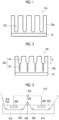
- Fig. 1 is a schematic cross-sectional view illustrating an embodiment of an aluminum support 12a.
- the aluminum support 12a has a laminated structure in which an aluminum plate 18 and an anodized aluminum film 20a (hereinafter, also simply referred to as an "anodized film 20a") are laminated in this order. Further, the anodized film 20a in the aluminum support 12a is positioned closer to the side of the image recording layer than the side of the aluminum plate 18. That is, it is preferable that the planographic printing plate precursor according to the embodiment of the presently claimed invention includes at least an anodized film, an image recording layer, and a water-soluble resin layer in order, on the aluminum plate.
- the anodized film 20a is a film to be prepared on a surface of the aluminum plate 18 by performing an anodization treatment, and this film is substantially perpendicular to the film surface and has extremely fine micropores 22a uniformly distributed.
- the micropores 22a extend along the thickness direction (the aluminum plate 18 side) from the surface (the surface of the anodized film 20a on a side opposite to a side where the aluminum plate 18 is provided) of the anodized film 20a on the side of the image recording layer.
- the average diameter (average opening diameter) of the micropores 22a in the surface of the anodized film 20a is preferably greater than 10 nm and 100 nm or less. From the viewpoint of the balance between the printing durability, the stain resistance, and the image visibility, the average diameter thereof is more preferably in a range of 15 nm to 60 nm, still more preferably in a range of 20 nm to 50 nm, and particularly preferably in a range of 25 nm to 40 nm.
- the diameter inside the pores may be larger or smaller than that of the surface layer.
- the printing durability and the image visibility are more excellent. Further, in a case where the average diameter thereof is 100 nm or less, the printing durability is more excellent.
- FE-SEM field emission scanning electron microscope
- an equivalent circle diameter is used.
- the "equivalent circle diameter” is a diameter of a circle obtained by assuming the shape of an opening portion of a micropore as a circle having the same projected area as the projected area of the opening portion.
- the depth of the micropores 22a is not particularly limited, but is preferably in a range of 10 nm to 3000 nm, more preferably in a range of 50 nm to 2000 nm, and still more preferably in a range of 300 nm to 1600 nm.
- the depth thereof is a value obtained by capturing (150000 times) an image of a cross section of the anodized film 20a, measuring the depth of 25 or more micropores 22a, and averaging the obtained values.
- the shape of the micropores 22a is not particularly limited, and the shape thereof in Fig. 2 may be a substantially straight tubular shape (substantially cylindrical shape), but may be a conical shape whose diameter decreases toward the depth direction (thickness direction). Further, the shape of the bottom portion of the micropores 22a is not particularly limited, but may be a curved shape (projection shape) or a planar shape.
- the value of the brightness L* in the L*a*b* color system of the surface of the aluminum support 12a on the side of the image recording layer is preferably in a range of 70 to 100.
- the value thereof is preferably in a range of 75 to 100 and more preferably in a range of 75 to 90.
- the brightness L* is measured using a color difference meter Spectro Eye (manufactured by X-Rite Inc.).
- Fig. 2 is a schematic cross-sectional view illustrating another embodiment of the aluminum support 12a other than the aluminum support illustrated in Fig. 1 .
- a support B is an embodiment of the aluminum support 12a illustrated in Fig. 2 .
- an aluminum support 12b includes the aluminum plate 18 and an anodized film 20b having micropores 22b formed of large-diameter pores 24 and small-diameter pores 26.
- the micropores 22b in the anodized film 20b are formed of large-diameter pores 24 extending to a position at a depth (depth D: see Fig. 2 ) of 10 nm to 1000 nm from the surface of the anodized film and small-diameter pores 26 communicating with bottom portions of the large-diameter pores 24 and extending to a position at a depth of 20 nm to 2000 nm from the communication positions.
- the average diameter of the large-diameter pores 24 in the surface of the anodized film 20b is the same as the average diameter of the micropores 22a in surface of the anodized film 20a, which is greater than 10 nm and 100 nm or less, and the preferable ranges thereof are also the same as described above.
- the method of measuring the average diameter of the large-diameter pores 24 in the surface of the anodized film 20b is the same as the method of measuring the average diameter of the micropores 22a in the surface of the anodized film 20a.
- the bottom portions of the large-diameter pores 24 are positioned at a depth of 10 to 1000 nm (hereinafter, also referred to as a depth D) from the surface of the anodized film. That is, the large-diameter pores 24 are pores extending from the surface of the anodized film to a position at a depth of 10 nm to 1000 nm in the depth direction (thickness direction). The depth thereof is preferably in a range of 10 nm to 200 nm.
- the depth thereof is a value obtained by capturing (at a magnification of 150000) an image of a cross section of the anodized film 20b, measuring the depth of 25 or more large-diameter pores 24, and averaging the obtained values.
- the shape of the large-diameter pores 24 is not particularly limited, and examples thereof include a substantially straight tubular shape (substantially cylindrical shape) and a conical shape whose diameter decreases toward the depth direction (thickness direction). Among these, a substantially straight tubular shape is preferable.
- the small-diameter pores 26, as illustrated in Fig. 2 are pores communicating with the bottom portions of the large-diameter pores 24 and extending from the communication positions in the depth direction (thickness direction).
- the average diameter of the small-diameter pores 26 in the communication position is preferably 13 nm or less. Further, the average diameter thereof is preferably 11 nm or less and more preferably 10 nm or less. The lower limit thereof is not particularly limited, but is 5 nm or greater in many cases.
- the average diameter of small-diameter pores may be acquired by cutting (for example, cutting the upper portion using argon gas) the upper portion (a region where large-diameter pores are present) of the anodized film 20b as necessary and observing the surface of the anodized film 20b using the above-described FE-SEM.
- an equivalent circle diameter is used.
- the "equivalent circle diameter” is a diameter of a circle obtained by assuming the shape of an opening portion of a micropore as a circle having the same projected area as the projected area of the opening portion.
- the bottom portions of the small-diameter pores 26 are at a position extending from the communication positions with the large-diameter pores 24 to a depth of 20 to 2000 nm in the depth direction. That is, the small-diameter pores 26 are pores extending from the communication positions with the large-diameter pores 24 in the depth direction (thickness direction), and the depth of the small-diameter pores 26 is in a range of 20 nm to 2000 nm. Further, the depth thereof is preferably in a range of 500 to 1500 nm.
- the depth thereof is a value obtained by capturing (50000 times) an image of a cross section of the anodized film 20b, measuring the depth of 25 or more small-diameter pores, and averaging the obtained values.
- the shape of the small-diameter pores 26 is not particularly limited, and examples thereof include a substantially straight tubular shape (substantially cylindrical shape) and a conical shape whose diameter decreases toward the depth direction. Among these, a substantially straight tubular shape is preferable.
- the image recording layer in the planographic printing plate precursor according to the embodiment of the presently claimed invention contains an infrared absorbing agent that is decomposed by exposure to infrared rays, a polymer having a structural unit formed of an aromatic vinyl compound, a polymerization initiator, and a polymerizable compound.
- the unexposed portion of the image recording layer can be removed by at least one selected from the group consisting of dampening water and printing ink.
- the image recording layer in the planographic printing plate precursor according to the presently claimed invention contains an infrared absorbing agent that is decomposed by exposure to infrared rays (hereinafter, also referred to as a "decomposable infrared absorbing agent").
- the decomposable infrared absorbing agent contained in the image recording layer is an infrared absorbing agent having a function of absorbing infrared rays, being decomposed, and performing color development by exposure to infrared rays.
- the "color development” indicates that absorption does not almost occur in the visible light region (a wavelength range of 400 nm or greater and less than 750 nm) before exposure to infrared rays, but absorption occurs in the visible light region due to exposure to infrared rays, and the color development also includes a case where absorption in a wavelength range lower than the visible light region increases the wavelength in the visible light region.
- a color developing compound formed such that a decomposable infrared absorbing agent absorbs infrared rays and decomposed by exposure to infrared rays is also referred to as a "color developing body of a decomposable infrared absorbing agent”.
- the decomposable infrared absorbing agent has a function of absorbing infrared rays by exposure to infrared rays and converting the absorbed infrared rays to heat.
- the decomposable infrared absorbing agent is not limited as long as the agent absorbs at least a part of light in the infrared wavelength range (wavelength of 750 nm to 1 mm) and is decomposed, and an infrared absorbing agent having a maximum absorption in a wavelength range of 750 nm to 1400 nm is preferable.
- the decomposable infrared absorbing agent is an infrared absorbing agent that is decomposed due to heat, electron transfer, or both thereof caused by exposure to infrared rays and more preferable that the decomposable infrared absorbing agent is an infrared absorbing agent that is decomposed due to electron transfer caused by exposure to infrared rays.
- the expression of "decomposed due to electron transfer” indicates that electrons excited to LUMO (lowest unoccupied molecular orbital) from HOMO (highest occupied molecular orbital) of the decomposable infrared absorbing agent by exposure to infrared rays show intramolecular electron transfer to an electron-accepting group (a group having a potential close to that of LUMO) in a molecule and decomposition occurs accordingly.
- a cyanine coloring agent that is decomposed by exposure to infrared rays is preferable as the decomposable infrared absorbing agent.
- a cyanine coloring agent represented by Formula 1 is more preferable as the cyanine coloring agent that is decomposed by exposure to infrared rays.
- R 1 represents a group having an R 1 -L bond that is cleaved by exposure to infrared rays
- R 11 to R 18 each independently represent a hydrogen atom, a halogen atom, -Ra, -ORb, -SRc, or -NRdRe
- Ra to Re each independently represent a hydrocarbon group
- a 1 , A 2 and a plurality of R 11 's to R 18 's are linked to each other to form a monocycle or a polycycle
- a 1 and A 2 each independently represent an oxygen atom, a sulfur atom, or a nitrogen atom
- n 11 and n 12 each independently represent an integer of 0 to 5, where a total of n 11 and n 12 is 2 or greater
- n 13 and n 14 each independently represent 0 or 1
- L represents an oxygen atom, a sulfur atom, or -NR 10 -
- R 10 represents a hydrogen atom, an alkyl group, or an aryl group
- R 1 is released to form a radical body or an ionic body.
- R 11 to R 18 each independently represent a hydrogen atom, -Ra, -ORb, -SRc, or -NRdRe.
- hydrocarbon groups represented by Ra to Re a hydrocarbon group having 1 to 30 carbon atoms (the number of carbon atoms) is preferable, a hydrocarbon group having 1 to 15 carbon atoms is more preferable, and a hydrocarbon group having 1 to 10 carbon atoms is still more preferable.
- the hydrocarbon group may be linear, branched, or cyclic.
- R 11 to R 14 in Formula 1 each independently represent preferably a hydrogen atom or a hydrocarbon group, more preferably a hydrogen atom or an alkyl group, and still more preferably a hydrogen atom.
- R 11 and R 13 bonded to the carbon atoms which bond to the carbon atom to which L is bonded represent an alkyl group and more preferable that R 11 and R 13 are linked to each other to form a ring.
- the ring to be formed is preferably a 5-membered ring or a 6-membered ring and more preferably a 5-membered ring.
- R 12 bonded to the carbon atom to which A 1 + is bonded and R 14 bonded to the carbon atom to which A 2 is bonded are respectively linked to R 15 and R 17 to form a ring.
- R 15 in Formula 1 represents a hydrocarbon group. Further, it is preferable that R 15 and R 12 bonded to the carbon atom to which A 1 + is bonded are linked to each other to form a ring.
- a ring to be formed an indolium ring, a pyrylium ring, a thiopyrylium ring, a benzoxazoline ring, or a benzoimidazoline ring is preferable. Among these, from the viewpoint of the color developability, an indolium ring is more preferable.
- R 17 in Formula 1 represents a hydrocarbon group. Further, it is preferable that R 17 and R 14 bonded to the carbon atom to which A 2 is bonded are linked to each other to form a ring.
- a ring to be formed an indole ring, a pyran ring, a thiopyran ring, a benzoxazole ring, or a benzimidazole ring is preferable. Among these, from the viewpoint of the color developability, an indole ring is more preferable.
- R 15 and R 17 in Formula 1 represent the same group, and in a case where R 15 and R 17 each form a ring, it is preferable to form the same ring.
- R 16 and R 18 in Formula 1 represent the same group.
- R 16 and R 18 each independently represent preferably an alkyl group containing a (poly)oxyalkylene group or an alkyl group having an anion structure, more preferably an alkyl group containing an alkoxyalkyl group, a carboxylate group, or a sulfonate group, and still more preferably an alkyl group containing a sulfonate group at the terminal.
- an alkyl group having 1 to 10 carbon atoms is preferable, and an alkyl group having 1 to 4 carbon atoms is more preferable.
- the counter cation of the anion structure may be a cation that can be contained in R 1 -L in Formula 1 or A 1 + or may also be an alkali metal cation or an alkaline earth metal cation.
- the counter cation of the sulfonate group may be a cation that can be contained in R 1 -L in Formula 1 or A 1 + or may also be an alkali metal cation or an alkaline earth metal cation.
- R 16 and R 18 each independently represent an alkyl group or an alkyl group having an aromatic ring.
- an alkyl group having 1 to 10 carbon atoms is preferable, an alkyl group having 1 to 4 carbon atoms is more preferable, and a methyl group or an ethyl group is still more preferable.
- an alkyl group having an aromatic ring at the terminal is preferable, and a 2-phenylethyl group, a 2-naphthalenylethyl group, or a 2-(9-anthracenyl)ethyl group is more preferable.
- Both n 11 and n 12 in Formula 1 represent preferably an integer of 0 to 5, more preferably an integer of 1 to 3, still more preferably 1 or 2, and particularly preferably 2 at the same time.
- a 1 and A 2 in Formula 1 each independently represent an oxygen atom, a sulfur atom, or a nitrogen atom and preferably a nitrogen atom.
- both A 1 and A 2 in Formula 1 represent the same atom at the same time.
- Za in Formula 1 represents a counter ion that neutralizes the electric charge.
- Za represents an anionic species
- examples thereof include a sulfonate ion, a carboxylate ion, a tetrafluoroborate ion, a hexafluorophosphate ion, a hexafluoroantimonate ion, a p-toluenesulfonate ion, and a perchlorate ion.
- a hexafluorophosphate ion or a hexafluoroantimonate ion is preferable.
- Za represents a cationic species
- examples thereof include an alkali metal ion, an alkaline earth metal ion, an ammonium ion, a pyridinium ion, and a sulfonium ion.
- a sodium ion, a potassium ion, an ammonium ion, a pyridinium ion, or a sulfonium ion is preferable, and a sodium ion, a potassium ion, or an ammonium ion is more preferable.
- R 11 to R 18 and R 1 -L may have an anion structure or a cation structure, and in a case where all R 11 to R 18 and R 1 -L represent a charge-neutral group, Za represents a monovalent counter anion. However, for example, in a case where R 11 to R 18 and R 1 -L have two or more anion structures, Za may represent a counter cation.
- Za is not present.
- a cyanine coloring agent represented by Formula 2 is more preferable as the cyanine coloring agent decomposed by exposure to infrared rays.
- R 1 represents a group having an R 1 -L bond that is cleaved by exposure to infrared rays
- R 2 and R 3 each independently represent a hydrogen atom or an alkyl group
- R 2 and R 3 may be linked to each other to form a ring
- Ar 1 and Ar 2 each independently represent a group forming a benzene ring or a naphthalene ring
- Y 1 and Y 2 each independently represent an oxygen atom, a sulfur atom, -NR 0 -, or a dialkylmethylene group
- R 0 represents a hydrogen atom, an alkyl group, or an aryl group
- R 4 and R 5 each independently represent an alkyl group, a -CO 2 M group, or a -PO 3 M 2 group
- M represents a hydrogen atom, a Na atom, a K atom, or an onium group
- R 6 to R 9 each independently represent a hydrogen atom or an alkyl group
- an alkyl group having 1 to 30 carbon atoms is preferable, an alkyl group having 1 to 15 carbon atoms is more preferable, and an alkyl group having 1 to 10 carbon atoms is still more preferable.
- the alkyl group may be linear, branched, or cyclic.
- alkyl group examples include a methyl group, an ethyl group, a propyl group, a butyl group, a pentyl group, a hexyl group, a heptyl group, an octyl group, a nonyl group, a decyl group, an undecyl group, a dodecyl group, a tridecyl group, a hexadecyl group, an octadecyl group, an eicosyl group, an isopropyl group, an isobutyl group, an s-butyl group, a tert-butyl group, an isopentyl group, a neopentyl group, a 1-methylbutyl group, an isohexyl group, a 2-ethylhexyl group, a 2-methylhexyl group, a cyclohexyl group, a cyclohe
- a methyl group, an ethyl group, a propyl group, or a butyl group is preferable.
- the alkyl group may have a substituent.
- substituents include an alkoxy group, an aryloxy group, an amino group, an alkylthio group, an arylthio group, a halogen atom, a carboxy group, a carboxylate group, a sulfo group, a sulfonate group, an alkyloxycarbonyl group, an aryloxycarbonyl group, and a group obtained by combining these groups.
- an aryl group having 6 to 30 carbon atoms is preferable, an aryl group having 6 to 20 carbon atoms is more preferable, and an aryl group having 6 to 12 carbon atoms is still more preferable.
- the aryl group may have a substituent.
- substituents include an alkyl group, an alkoxy group, an aryloxy group, an amino group, an alkylthio group, an arylthio group, a halogen atom, a carboxy group, a carboxylate group, a sulfo group, a sulfonate group, an alkyloxycarbonyl group, an aryloxycarbonyl group, and a group obtained by combining these groups.
- a phenyl group a naphthyl group, a p-tolyl group, a p-chlorophenyl group, a p-fluorophenyl group, a p-methoxyphenyl group, a p-dimethylaminophenyl group, a p-methylthiophenyl group, and p-phenylthiophenyl group.
- aryl groups a phenyl group, a p-methoxyphenyl group, a p-dimethylaminophenyl group, or a naphthyl group is preferable.
- R 2 and R 3 are linked to each other to form a ring.
- a 5-membered ring or a 6-membered ring is preferable, and a 5-membered ring is particularly preferable.
- Y 1 and Y 2 each independently represent an oxygen atom, a sulfur atom, -NR 0 -, or a dialkylmethylene group, preferably -NR 0 - or a dialkylmethylene group, and more preferably a dialkylmethylene group.
- R 0 represents a hydrogen atom, an alkyl group, or an aryl group and preferably an alkyl group.
- the alkyl group represented by R 4 or R 5 may be substituted alkyl.
- Examples of the substituted alkyl group represented by R 4 or R 5 include a group represented by any of Formulae (a1) to (a4).
- R W0 represents an alkylene group having 2 to 6 carbon atoms
- W represents a single bond or an oxygen atom
- n W1 represents an integer of 1 to 45
- R W5 represents an alkyl group having 1 to 12 carbon atoms
- R W2 to R W4 each independently represent a single bond or an alkylene group having 1 to 12 carbon atoms
- M represents a hydrogen atom, a Na atom, a K atom, or an onium group.
- alkylene group represented by R W0 examples include an ethylene group, an n-propylene group, an isopropylene group, an n-butylene group, an isobutylene group, an n-pentylene group, an isopentylene group, an n-hexyl group, and an isohexyl group.
- an ethylene group, an n-propylene group, an isopropylene group, or an n-butylene group is preferable, and an n-propylene group is particularly preferable.
- n W1 represents preferably 1 to 10, more preferably 1 to 5, and particularly preferably 1 to 3.
- alkyl group represented by R W1 examples include a methyl group, an ethyl group, an n-propyl group, an isopropyl group, an n-butyl group, an isobutyl group, a tert-butyl group, an n-pentyl group, an isopentyl group, a neopentyl group, an n-hexyl group, an n-octyl group, and an n-dodecyl group.
- a methyl group, an ethyl group, an n-propyl group, an isopropyl group, an n-butyl group, or a tert-butyl group is preferable, a methyl group or an ethyl group is more preferable, and a methyl group is particularly preferable.
- the alkyl group represented by R W5 has the same definition as that for the alkyl group represented by R W1 , and the preferred embodiment thereof is the same as the preferred embodiment of the alkyl group represented by R W1 .
- Me represents a methyl group
- Et represents an ethyl group
- "*" represents a bonding site
- alkylene group represented by R W2 to R W4 include a methylene group, an ethylene group, an n-propylene group, an isopropylene group, an n-butylene group, an isobutylene group, an n-pentylene group, an isopentylene group, an n-hexyl group, an isohexyl group, an n-octylene group, and an n-dodecylene group.
- an ethylene group, an n-propylene group, an isopropylene group, or an n-butylene group is preferable, and an ethylene group or an n-propylene group is particularly preferable.
- two M's may be the same as or different from each other.
- examples of the onium group represented by M include an ammonium group, an iodonium group, a phosphonium group, and a sulfonium group.
- the group represented by Formula (a1) or Formula (a4) is preferable.
- R 4 and R 5 each represent an unsubstituted alkyl group. It is preferred that both R 4 and R 5 represent the same group.
- R 6 to R 9 each independently represent a hydrogen atom or an alkyl group and preferably a hydrogen atom.
- Ar 1 and Ar 2 each independently represent a group that forms a benzene ring or a naphthalene ring.
- the benzene ring and the naphthalene ring may have a substituent.
- the substituent include an alkyl group, an alkoxy group, an aryloxy group, an amino group, an alkylthio group, an arylthio group, a halogen atom, a carboxy group, a carboxylate group, a sulfo group, a sulfonate group, an alkyloxycarbonyl group, an aryloxycarbonyl group, an acyloxy group, a phosphonic acid group, and a group obtained by combining these groups.
- an alkyl group is preferable.
- Ar 1 and Ar 2 each independently represent preferably a naphthalene ring or a group that forms a benzene ring containing an alkyl group or an alkoxy group as a substituent, more preferably a naphthalene ring or a group that forms a benzene ring containing an alkoxy group as a substituent, and particularly preferably a naphthalene ring or a group that forms a benzene ring containing a methoxy group as a substituent.
- Ar 1 or Ar 2 represents a group that forms a group represented by Formula (b1).
- R 19 represents an alkyl group having 1 to 12 carbon atoms.
- n3 represents an integer of 1 to 4.
- "*" represents a bonding site.
- Za represents a counter ion for neutralizing the electric charge.
- Za represents an anionic species
- examples thereof include a sulfonate ion, a carboxylate ion, a tetrafluoroborate ion, a hexafluorophosphate ion, a hexafluoroantimonate ion, a p-toluenesulfonate ion, and a perchlorate ion.
- a hexafluorophosphate ion or a hexafluoroantimonate ion is preferable.
- Za represents a cationic species
- examples thereof include an alkali metal ion, an alkaline earth metal ion, an ammonium ion, a pyridinium ion, and a sulfonium ion.
- a sodium ion, a potassium ion, an ammonium ion, a pyridinium ion, or a sulfonium ion is preferable, and a sodium ion, a potassium ion, or an ammonium ion is more preferable.
- R 1 to R 9 , R 0 , Ar 1 , Ar 2 , Y 1 , and Y 2 may have an anion structure or a cation structure, and in a case where all R 1 to R 9 , R 0 , Ar 1 , Ar 2 , Y 1 , and Y 2 represent a charge-neutral group, Za represents a monovalent counter anion. However, for example, in a case where R 1 to R 9 , R 0 , Ar 1 , Ar 2 , Y 1 , and Y 2 have two or more anion structures, Za may represent a counter cation.
- R 1 represents preferably a group represented by any of Formulae (1-1) to (1-7) and more preferably a group represented by any of Formulae (1-1) to (1-3).
- R 20 's each independently represent a hydrogen atom, an alkyl group, an alkenyl group, an aryl group, -OR 24 , -NR 25 R 26 , or -SR 27
- R 21 's each independently represent a hydrogen atom, an alkyl group, or an aryl group
- R 23 represents an aryl group, an alkenyl group, an alkoxy group, or an onium group
- R 24 to R 27 each independently represent a hydrogen atom, an alkyl group, or an aryl group
- R 28 represents an alkyl group, an aryl group, -OR 24 , -NR
- R 20 , R 21 , and R 24 to R 28 represent an alkyl groups is the same as the preferred embodiment of the alkyl group as R 2 to R 9 and R 0 .
- the number of carbon atoms of the alkenyl group as R 20 and R 23 is preferably in a range of 1 to 30, more preferably in a range of 1 to 15, and still more preferably in a range of 1 to 10.
- R 20 to R 28 represent an aryl group
- R 20 to R 28 represent an aryl group
- R 20 in Formula (1-1) represents preferably an alkyl group, an alkenyl group, an aryl group, -OR 24 , -NR 25 R 26 , or -SR 27 , more preferably an alkyl group, -OR 24 , -NR 25 R 26 , or -SR 27 , still more preferably an alkyl group or -OR 24 , and particularly preferably -OR 24 .
- R 20 in Formula (1-1) represents an alkyl group
- the alkyl group may be an alkyl group having an arylthio group, an alkyloxycarbonyl group, or an arylsulfonyl group at the ⁇ -position and preferably having an arylthio group or an alkyloxycarbonyl group at the ot-position.
- R 24 represents preferably an alkyl group, more preferably an alkyl group having 1 to 8 carbon atoms, still more preferably an isopropyl group or a tert-butyl group, and particularly preferably a t-butyl group.
- R 20 in Formula (1-1) represents an alkenyl group
- the alkenyl group may be an alkenyl group containing an aryl group or a hydroxyaryl group.
- R 21 in Formula (1-2) represents a hydrogen atom.
- R 21 's in Formula (1-3) each independently represent a hydrogen atom or an alkyl group and more preferable that at least one R 21 in Formula (1-3) represents an alkyl group.
- alkyl group represented by R 21 an alkyl group having 1 to 10 carbon atoms is preferable, and an alkyl group having 3 to 10 carbon atoms is more preferable.
- alkyl group represented by R 21 a branched or cyclic alkyl group is preferable, and an isopropyl group, a cyclopentyl group, a cyclohexyl group, or a tert-butyl group is more preferable. Further, it is preferable that the alkyl group as R 21 is a secondary or tertiary alkyl group.
- R 23 in Formula (1-3) represents preferably an aryl group, an alkoxy group, or an onium group, more preferably a p-dimethylaminophenyl group, or a pyridinium group, and still more preferably a pyridinium group.
- Examples of the onium group as R 23 include a pyridinium group, an ammonium group, and a sulfonium group.
- the onium group may have a substituent.
- Examples of the substituent include an alkyl group, an alkoxy group, an aryloxy group, an amino group, an alkylthio group, an arylthio group, a halogen atom, a carboxy group, a sulfo group, an alkyloxycarbonyl group, an aryloxycarbonyl group, and a group obtained by combining these groups.
- an alkyl group, an aryl group, or a group obtained by combining these groups is preferable.
- a pyridinium group is preferable, a N-alkyl-3-pyridinium group, a N-benzyl-3-pyridinium group, a N-(alkoxypolyalkyleneoxyalkyl)-3-pyridinium group, a N-alkoxycarbonylmethyl-3-pyridinium group, a N-alkyl-4-pyridinium group, a N-benzyl-4-pyridinium group, a N-(alkoxypolyalkyleneoxyalkyl)-4-pyridinium group, a N-alkoxycarbonylmethyl-4-pyridinium group, or a N-alkyl-3,5-dimethyl-4-pyridinium group is more preferable, a N-alkyl-3-pyridinium group or a N-alkyl-4-pyridinium group is still more preferable, a N-methyl-3-pyridinium group, a N-octyl-3-pyridinium group,
- examples of the counter anion include a sulfonate ion, a carboxylate ion, a tetrafluoroborate ion, a hexafluorophosphate ion, a hexafluoroantimonate ion, a p-toluenesulfonate ion, and a perchlorate ion.
- a p-toluenesulfonate ion, a hexafluorophosphate ion, or a hexafluoroantimonate ion is preferable.
- R 20 in Formula (1-4) represents an alkyl group or an aryl group and more preferable that one of two R 20 's represents an alkyl group and the other represents an aryl group. Two R 20 's may be linked to each other to form a ring.
- R 20 in Formula (1-5) represents preferably an alkyl group or an aryl group, more preferably an aryl group, and still more preferably a p-methylphenyl group.
- R 20 's in Formula (1-6) each independently represent an alkyl group or an aryl group and more preferably a methyl group or a phenyl group.
- Z 1 in Formula (1-7) may represent a counter ion for neutralizing the electric charge, and the entire compound may be included in Za.
- Z 1 represents preferably a sulfonate ion, a carboxylate ion, a tetrafluoroborate ion, a hexafluorophosphate ion, a hexafluoroantimonate ion, a p-toluenesulfonate ion, or a perchlorate ion and more preferably a p-toluenesulfonate ion, a hexafluorophosphate ion, or a hexafluoroantimonate ion.
- R 1 represents a group represented by Formula (5).
- R 15 and R 16 each independently represent a hydrogen atom, an alkyl group, or an aryl group, E represents an onium group, and "*" represents a bonding site with respect to the oxygen atom represented by L in Formula 1 or 2.
- the alkyl group represented by R 15 or R 16 has the same definition as that for the alkyl group represented by R 2 to R 9 and R 0 , and the preferred embodiment thereof is also the same as the preferred embodiment of the alkyl group represented by R 2 to R 9 and R 0 .
- the aryl group represented by R 15 or R 16 has the same definition as that for the aryl group represented by R 0 , and the preferred embodiment thereof is also the same as the preferred embodiment of the aryl group represented by R 0 .
- the onium group represented by E has the same definition as that for the onium group represented by R 23 , and the preferred embodiment thereof is also the same as the preferred embodiment of the onium group represented by R 23 .
- R 17 represents a halogen atom, an alkyl group, an aryl group, a hydroxy group, or an alkoxy group, and in a case where a plurality of R 17 's are present, the plurality of R 17 's may be the same as or different from each other, or the plurality of R 17 's may be linked to each other to form a ring.
- n2 represents an integer of 0 to 4.
- R 18 represents an alkyl group or an aryl group.
- Z b represents a counter ion for neutralizing the electric charge.
- the alkyl group or the aryl group represented by R 17 or R 18 has the same definition as that for the alkyl group as R 2 to R 9 and R 0 or the aryl group as R 0 , and the preferred embodiment thereof is the same as the preferred embodiment of the alkyl group as R 2 to R 9 and R 0 or the aryl group as R 0 .
- an alkoxy group having 1 to 10 carbon atoms is preferable, and examples thereof include a methoxy group, an ethoxy group, an n-propoxy group, an isopropoxy group, an n-butoxy group, an isobutoxy group, and a tert-butoxy group.
- n2 represents 0.
- the counter ion for neutralizing the electric charge represented by Z b has the same definition as that for Z 1 in Formula (1-7), and the preferred embodiment thereof is the same as the preferred embodiment of Z 1 in Formula (1-7).
- TsO - represents a tosylate anion
- "•" represents a bonding site with respect to an oxygen atom represented by L in Formula 1 or Formula 2.
- R 1 represents a group represented by Formula (2-1).
- R 1 bonded to N represents a group represented by Formula (3-1).
- the alkyl group, the aryl group, the alkenyl group, the alkoxy group, and the onium group represented by R 21 and R 22 can refer to the description of the alkyl group, the aryl group, the alkenyl group, the alkoxy group, and the onium group described in Formulae (1-1) to (1-7).
- L represents a sulfur atom or -NR 10 - and R 10 represents a hydrogen atom, an alkyl group, or an aryl group.
- infrared absorbing agent that is decomposed by exposure to infrared rays
- those described in JP2008-544322A or WO2016/027886A can be suitably used.
- the compound represented by Formula 1 or 2 can be synthesized by applying a known method.
- the compound represented by Formula 1 can be synthesized according to the following scheme 1 or scheme 2.
- a method in conformity with the following scheme 1 is suitably used.
- a method in conformity with the following scheme 2 is suitably used.
- a synthetic scheme represented by any of Formulae (S 1) to (S3) is suitably used.
- a synthetic scheme represented by Formula (S4) is suitably used.
- DMAP represents N, N-dimethylamino-4-pyridine
- AcONa represents sodium acetate
- NEt 3 represents triethylamine
- catecol represents catechol.
- R represents a group corresponding to each portion in Formula 2.
- the decomposable infrared absorbing agent may be used alone or in combination of two or more kinds thereof.
- the content of the decomposable infrared absorbing agent in the image recording layer is preferably in a range of 0.1% by mass to 95% by mass, more preferably in a range of 0.5% by mass to 40% by mass, and still more preferably in a range of 1% by mass to 20% by mass with respect to total mass of the image recording layer.
- the decomposable infrared absorbing agent has excellent infrared absorbing performance, and thus functions as an infrared absorbing agent satisfactorily. Therefore, in a case where the decomposable infrared absorbing agent is used for the image recording layer of the planographic printing plate precursor, it is practically unnecessary to use infrared absorbing agents other than the decomposable infrared absorbing agent, but the image recording layer may contain other infrared absorbing agents.
- the image recording layer may contain infrared absorbing agents other than the decomposable infrared absorbing agent.
- Examples of other infrared absorbing agents include pigments and dyes.
- dyes used as other infrared absorbing agents commercially available dyes and known dyes described in the literatures such as " Dye Handbook” (edited by the Society of Synthetic Organic Chemistry, Japan, published in 1970 ) can be used. Specific examples thereof include dyes such as an azo dye, a metal complex salt azo dye, a pyrazolone azo dye, a naphthoquinone dye, an anthraquinone dye, a phthalocyanine dye, a carbonium dye, a quinone imine dye, a methine dye, a cyanine dye, a squarylium coloring agent, a pyrylium salt, and a metal thiolate complex.
- dyes such as an azo dye, a metal complex salt azo dye, a pyrazolone azo dye, a naphthoquinone dye, an anthraquinone dye, a phthalocyanine dye, a carbonium dye, a quinone imine dye,
- a cyanine coloring agent a squarylium coloring agent, a pyrylium salt, a nickel thiolate complex, and an indolenine cyanine coloring agent are particularly preferable. Further, other examples thereof include a cyanine coloring agent and an indolenine cyanine coloring agent. Among these, a cyanine coloring agent is particularly preferable.
- cyanine coloring agent examples include compounds described in paragraphs 0017 to 0019 of JP2001-133969A and compounds described in paragraphs 0016 to 0021 of JP2002-023360A and paragraphs 0012 to 0037 of JP2002-040638A , preferred examples thereof include compounds described in paragraphs 0034 to 0041 of JP2002-278057A and paragraphs 0080 to 0086 of JP2008-195018A , and particularly preferred examples thereof include compounds described in paragraphs 0035 to 0043 of JP2007-090850A and compounds described in paragraphs 0105 to 0113 of JP2012-206495A .
- infrared absorbing agents may be used alone or in combination of two or more kinds thereof. Further, pigments and dyes may be used in combination as other infrared absorbing agents.
- the content of other infrared absorbing agents in the image recording layer is smaller than the content of the decomposable infrared absorbing agent and more preferable that the image recording layer does not contain other infrared absorbing agents.
- the image recording layer used in the presently claimed invention contains a polymer having a structural unit formed of an aromatic vinyl compound.
- the polymer having a structural unit formed of an aromatic vinyl compound further has a structural unit formed of an acrylonitrile compound.
- the polymer having a structural unit formed of an aromatic vinyl compound is also referred to as a specific polymer.
- the specific polymer has a structural unit formed of an aromatic vinyl compound.
- the aromatic vinyl compound may be a compound having a structure in which a vinyl group is bonded to an aromatic ring, and examples thereof include a styrene compound and a vinylnaphthalene compound. Among these, a styrene compound is preferable, and styrene is more preferable.
- styrene compound examples include styrene, p-methylstyrene, p-methoxystyrene, ⁇ -methylstyrene, p-methyl- ⁇ -methylstyrene, ⁇ -methylstyrene, and p-methoxy- ⁇ -methylstyrene. Among these, styrene is preferable.
- vinylnaphthalene compound examples include 1-vinylnaphthalene, methyl-1-vinylnaphthalene, ⁇ -methyl-1-vinylnaphthalene, 4-methyl-1-vinylnaphthalene, and 4-methoxy-1-vinylnaphthalene. Among these, 1-vinylnaphthalene is preferable.
- preferred examples of the structural unit formed of the aromatic vinyl compound include a structural unit represented by Formula A1.
- R A1 and R A2 each independently represent a hydrogen atom or an alkyl group
- Ar represents an aromatic ring group
- R A3 represents a substituent
- n represents an integer less than or equal to the number of substituents of Ar.
- R A1 and R A2 each independently represent preferably a hydrogen atom or an alkyl group having 1 to 4 carbon atoms, more preferably a hydrogen atom or a methyl group, and still more preferably a hydrogen atom.
- Ar represents preferably a benzene ring or a naphthalene ring and more preferably a benzene ring.
- R A3 represents preferably an alkyl group or an alkoxy group, more preferably an alkyl group having 1 to 4 carbon atoms or an alkoxy group having 1 to 4 carbon atoms, and still more preferably a methyl group or a methoxy group.
- the plurality of R A3 's may be the same as or different from each other.
- n represents preferably an integer of 0 to 2, more preferably 0 or 1, and still more preferably 0.
- the content of the structural unit formed of an aromatic vinyl compound in the specific polymer is preferably in a range of 15% by mass to 85% by mass and more preferably in a range of 30% by mass to 70% by mass with respect to the total mass of the specific polymer.
- the specific polymer further has a structural unit formed of an acrylonitrile compound.
- acrylonitrile compound examples include (meth)acrylonitrile. Among examples, acrylonitrile is preferable.
- preferred examples of the structural unit formed of the acrylonitrile compound include a structural unit represented by Formula B1.
- R B1 represents a hydrogen atom or an alkyl group.
- R B1 represents preferably a hydrogen atom or an alkyl group having 1 to 4 carbon atoms, more preferably a hydrogen atom or a methyl group, and still more preferably a hydrogen atom.
- the content of the structural unit formed of an acrylonitrile compound in the specific polymer is preferably in a range of 5% by mass to 85% by mass and more preferably in a range of 8% by mass to 70% by mass with respect to the total mass of the specific polymer.
- the specific polymer further has a structural unit formed of a N-vinyl heterocyclic compound or a structural unit containing a hydrophilic group as described further below.
- N-vinyl heterocyclic compound examples include N-vinylpyrrolidone, N-vinylcarbazole, N-vinylpyrrole, N-vinylphenothiazine, N-vinylsuccinimide, N-vinylphthalimide, N-vinylcaprolactam, and N-vinylimidazole.
- N-vinylpyrrolidone is preferable.
- preferred examples of the structural unit formed of the N-vinyl heterocyclic compound include a structural unit represented by Formula C1.
- Ar N represents a heterocyclic structure having a nitrogen atom, and the nitrogen atom in Ar N is bonded to the carbon atom represented by "*".
- a pyrrolidone ring As the heterocyclic structure represented by Ar N , as the heterocyclic structure represented by Ar N , a pyrrolidone ring, a carbazole ring, a pyrrole ring, a phenothiazine ring, a succinimide ring, a phthalimide ring, a caprolactam ring, or an imidazole ring is preferable, and a pyrrolidone ring is more preferable.
- heterocyclic structure represented by Ar N may have a known substituent.
- the content of the structural unit formed of the N-vinyl heterocyclic compound in the specific polymer is preferably in a range of 5% by mass to 70% by mass and more preferably in a range of 10% by mass to 60% by mass with respect to the total mass of the specific polymer.
- the specific polymer may further have a structural unit containing an ethylenically unsaturated group.
- the ethylenically unsaturated group is not particularly limited, and examples thereof include a vinyl group, an allyl group, a vinylphenyl group, a (meth)acrylamide group, or a (meth)acryloyloxy group. Among these, from the viewpoint of the reactivity, a (meth)acryloyloxy group is preferable.
- the structural unit containing an ethylenically unsaturated group can be introduced to the specific polymer by a polymer reaction or copolymerization.
- the introduction can be carried out by, for example, a method of allowing a compound (such as glycidyl methacrylate) containing an epoxy group and an ethylenically unsaturated group to react with a polymer to which a structural unit containing a carboxy group such as methacrylic acid has been introduced or a method of allowing a compound (such as 2-isocyanatoethyl methacrylate) containing an isocyanate group and an ethylenically unsaturated group to react with a polymer to which a structural unit containing a group having active hydrogen such as a hydroxy group has been introduced.
- the structural unit containing an ethylenically unsaturated group may be introduced to the specific polymer according to, for example, a method of allowing a compound containing a carboxy group and an ethylenically unsaturated group to react with a polymer to which a structural unit containing an epoxy group such as glycidyl (meth)acrylate has been introduced.
- the structural unit containing an ethylenically unsaturated group may be introduced to the specific polymer using, for example, a monomer having a partial structure represented by Formula d1 or Formula d2.
- the structural unit containing an ethylenically unsaturated group is introduced to the specific polymer by forming an ethylenically unsaturated group on a partial structure represented by Formula d1 or Formula d2 through an elimination reaction using a base compound, after the polymerization carried out using at least the monomer described above.
- R d represents a hydrogen atom or an alkyl group
- a d represents a halogen atom
- X d represents -O- or -NR N -
- R N represents a hydrogen atom or an alkyl group
- * represents a bonding site with respect to another structure.
- R d represents a hydrogen atom or a methyl group.
- a d represents a chlorine atom, a bromine atom, or an iodine atom.
- X d represents -O-.
- R N represents preferably a hydrogen atom or an alkyl group having 1 to 4 carbon atoms and more preferably a hydrogen atom.
- Examples of the structural unit containing an ethylenically unsaturated group include a structural unit represented by Formula D1.
- L D1 represents a single bond or a divalent linking group
- L D2 represents an (m + 1)-valent linking group
- X D1 and X D2 each independently represent -O- or -NR N -
- R N represents a hydrogen atom or an alkyl group
- R D1 and R D2 each independently represent a hydrogen atom or a methyl group
- m represents an integer of 1 or greater.
- L D1 represents a single bond.
- L D1 represents a divalent linking group, an alkylene group, an arylene group, or a divalent group in which two or more of these groups are bonded to each other is preferable, and an alkylene group having 2 to 10 carbon atoms or a phenylene group is more preferable.
- L D2 represents a group represented by any of Formulae D2 to D6.
- both X D1 and X D2 represent -O-. Further, in a case where at least one of X D1 or X D2 represents -NR N -, R N represents preferably a hydrogen atom or an alkyl group having 1 to 4 carbon atoms and more preferably a hydrogen atom.
- R D1 represents a methyl group.
- m represents preferably an integer of 1 to 4, more preferably 1 or 2, and still more preferably 1.
- L D3 to L D7 represent a divalent linking group
- L D5 and L D6 may be different from each other
- "*" represents a bonding site with respect to X D1 in Formula D1
- the wavy line represents a bonding site with respect to X D2 in Formula D1.
- L D3 represents preferably an alkylene group, an arylene group, or a group in which two or more of these groups are bonded to each other and more preferably an alkylene group having 1 to 10 carbon atoms, a phenylene group, or a group in which two or more of these groups are bonded to each other.
- L D4 represents preferably an alkylene group, an arylene group, or a group in which two or more of these groups are bonded to each other and more preferably an alkylene group having 1 to 10 carbon atoms, a phenylene group, or a group in which two or more of these groups are bonded to each other.
- L D5 represents preferably an alkylene group, an arylene group, or a group in which two or more of these groups are bonded to each other and more preferably an alkylene group having 1 to 10 carbon atoms, a phenylene group, or a group in which two or more of these groups are bonded to each other.
- L D6 represents preferably an alkylene group, an arylene group, or a group in which two or more of these groups are bonded to each other and more preferably an alkylene group having 1 to 10 carbon atoms, a phenylene group, or a group in which two or more of these groups are bonded to each other.
- L D7 represents preferably an alkylene group, an arylene group, or a group in which two or more of these groups are bonded to each other and more preferably an alkylene group having 1 to 10 carbon atoms, a phenylene group, or a group in which two or more of these groups are bonded to each other.
- R's each independently represent a hydrogen atom or a methyl group.
- the content of the structural unit having an ethylenically unsaturated group in the specific polymer is preferably in a range of 5% by mass to 60% by mass and more preferably in a range of 10% by mass to 30% by mass with respect to the total mass of the specific polymer.
- the specific polymer may have a structural unit containing an acidic group, but from the viewpoint of the on-press developability, it is preferable that the specific polymer does not have a structural unit containing an acidic group.
- the content of the structural unit containing an acidic group in the specific polymer is preferably 20% by mass or less, more preferably 10% by mass or less, and still more preferably 5% by mass or less with respect to the total mass of the specific polymer.
- the lower limit of the content thereof is not particularly limited and may be 0% by mass.
- the acid value of the specific polymer is preferably 160 mgKOH/g or less, more preferably 80 mgKOH/g or less, and still more preferably 40 mgKOH/g or less.
- the lower limit of the acid value thereof is not particularly limited, and may be 0 mgKOH/g.
- the acid value is acquired by a measuring method in conformity with JIS K0070: 1992.
- the specific polymer may have a structural unit containing a hydrophobic group.
- hydrophobic group examples include an alkyl group, an aryl group and an aralkyl group.
- a structural unit formed of an alkyl(meth)acrylate compound, an aryl(meth)acrylate compound, or an aralkyl(meth)acrylate compound is preferable, and a structural unit formed of an alkyl(meth)acrylate compound is more preferable.
- the number of carbon atoms in the alkyl group in the alkyl (meth)acrylate compound is preferably in a range of 1 to 10.
- the alkyl group may be linear or branched and may have a cyclic structure.
- Examples of the alkyl (meth)acrylate compound include methyl (meth)acrylate, ethyl (meth)acrylate, propyl (meth)acrylate, cyclohexyl (meth)acrylate, 2-ethylhexyl (meth)acrylate, and dicyclopentanyl (meth)acrylate.
- the aryl group in the aryl (meth)acrylate compound preferably has 6 to 20 carbon atoms and is more preferably a phenyl group. Further, the aryl group may have a known substituent. Preferred examples of the aryl (meth)acrylate compound include phenyl (meth)acrylate.
- the carbon number of the alkyl group in the aralkyl (meth)acrylate compound is preferably in a range of 1 to 10.
- the alkyl group may be linear or branched and may have a cyclic structure.
- the aryl group in the aralkyl(meth)acrylate compound preferably has 6 to 20 carbon atoms and is more preferably a phenyl group.
- Preferred examples of the aralkyl (meth)acrylate compound include benzyl (meth)acrylate.
- the content of the structural unit containing a hydrophobic group in the specific polymer is preferably in a range of 5% by mass to 50% by mass and more preferably in a range of 10% by mass to 30% by mass with respect to the total mass of the specific polymer.
- the specific polymer has a structural unit formed of a N-vinyl heterocyclic compound or a structural unit containing a hydrophilic group.
- hydrophilic group examples include -OH, -CONR 1 R 2 , R 1 and R 2 each independently represent a hydrogen atom, an alkyl group, an alkenyl group, or an aryl group, and R 1 and R 2 may be bonded to each other to form a ringand a group represented by Formula PO.
- hydrophilic groups -OH or a group represented by Formula PO is preferable, and -OH is more preferable.
- L P 's each independently represent an alkylene group
- R P represents a hydrogen atom or an alkyl group
- n represents an integer of 1 to 10.
- L P 's each independently represent preferably an ethylene group, a 1-methylethylene group, or a 2-methylethylene group and more preferably an ethylene group.
- R P represents preferably a hydrogen atom or an alkyl group having 1 to 18 carbon atoms, more preferably a hydrogen atom or an alkyl group having 1 to 10 carbon atoms, still more preferably a hydrogen atom or an alkyl group having 1 to 4 carbon atoms, and particularly preferably a hydrogen atom or a methyl group.
- n preferably an integer of 1 to 4.
- a structural unit formed of a hydroxyalkyl (meth)acrylate compound is preferable, and a structural unit formed of a hydroxyethyl (meth)acrylate compound is more preferable.
- a polyalkylene oxide structure is preferable, and a polyethylene oxide structure, a polypropylene oxide structure, or a polyethylene/propylene oxide structure is more preferable.
- the structural unit has preferably a polypropylene oxide structure and more preferably a polyethylene oxide structure and a polypropylene oxide structure.
- the content of the structural unit containing a hydrophilic group in the specific polymer is preferably in a range of 5% by mass to 60% by mass and more preferably in a range of 10% by mass to 30% by mass with respect to the total mass of the specific polymer.
- the specific polymer may further have other structural units.
- the specific polymer may have structural units other than the above-described structural units as other structural units without particular limitation, and examples thereof include structural units formed of an acrylamide compound, a vinyl ether compound, and the like.
- Examples of the acrylamide compound include (meth)acrylamide, N-methyl (meth)acrylamide, N-ethyl (meth)acrylamide, N-propyl (meth)acrylamide, N-butyl (meth)acrylamide, N,N'-dimethyl (meth)acrylamide, N,N'-diethyl (meth)acrylamide, N-hydroxyethyl (meth)acrylamide, N-hydroxypropyl (meth)acrylamide, and N-hydroxybutyl (meth)acrylamide.
- vinyl ether compound examples include methyl vinyl ether, ethyl vinyl ether, propyl vinyl ether, n-butyl vinyl ether, tert-butyl vinyl ether, 2-ethylhexyl vinyl ether, n-nonyl vinyl ether, lauryl vinyl ether, cyclohexyl vinyl ether, cyclohexyl methyl vinyl ether, 4-methylcyclohexyl methyl vinyl ether, benzyl vinyl ether, dicyclopentenyl vinyl ether, 2-dicyclopentenoxyethyl vinyl ether, methoxyethyl vinyl ether, ethoxyethyl vinyl ether, butoxyethyl vinyl ether, methoxyethoxyethyl vinyl ether, ethoxyethoxyethyl vinyl ether, methoxypolyethylene glycol vinyl ether, tetrahydrofurfuryl vinyl ether, 2-hydroxyethyl vinyl ether, 2-hydroxypropyl
- the content of other structural units in the specific polymer is preferably in a range of 5% by mass to 50% by mass and more preferably in a range of 10% by mass to 30% by mass with respect to the total mass of the specific polymer.
- the method of producing the specific polymer is not particularly limited, and the specific polymer can be produced by a known method.
- the specific polymer is obtained by polymerizing a styrene compound, an acrylonitrile compound, and as necessary, at least one selected from the group consisting of the N-vinyl heterocyclic compound, a compound used to form the structural unit containing an ethylenically unsaturated group, a compound used to form the structural unit containing an acidic group, a compound used to form the structural unit containing a hydrophobic group, and a compound used to form other structural units described above, according to a known method.
- the weight-average molecular weight of the specific polymer is preferably in a range of 3000 to 300000 and more preferably in a range of 5000 to 100000.
- each structural unit can be appropriately changed based on the preferable range of the content of each structural unit described above.
- m and n each independently represent an integer of 1 or greater.
- weight-average molecular weight of each compound shown in the specific examples above can be appropriately changed based on the preferable range of the weight-average molecular weight of the specific polymer described above.
- the specific polymer may be a binding resin that is not in the form of particles or may be in the form of particles.
- the specific polymer contains polymer particles.
- the polymer particles have a hydrophobic main chain and both a structural unit (i) containing a pendant-cyano group directly bonded to the hydrophobic main chain and a structural unit (ii) containing a pendant group having a hydrophilic polyalkylene oxide segment.
- an acrylic resin chain is preferably exemplified.
- Preferred examples of the pendant-cyano group include -[CH 2 CH(C°N)-] and -[CH 2 C(CH 3 )(C ⁇ N)-].
- the structural unit having a pendant-cyano group can be easily derived from an ethylene-based unsaturated monomer such as acrylonitrile or methacrylonitrile or a combination of these.
- alkylene oxide in the hydrophilic polyalkylene oxide segment ethylene oxide or propylene oxide is preferable and ethylene oxide is more preferable.
- the repetition number of alkylene oxide structures in the hydrophilic polyalkylene oxide segment is preferably in a range of 10 to 100, more preferably in a range of 25 to 75, and still more preferably in a range of 40 to 50.
- resin particles which have a hydrophobic main chain and both the structural unit (i) containing a pendant-cyano group directly bonded to the hydrophobic main chain and the structural unit (ii) containing a pendant group having a hydrophilic polyalkylene oxide segment those described in paragraphs 0039 to 0068 of JP2008-503365A are preferably exemplified.
- the average particle diameter of the polymer particles is preferably in a range of 0.01 ⁇ m to 3.0 ⁇ m, more preferably in a range of 0.03 ⁇ m to 2.0 ⁇ m, and still more preferably in a range of 0.10 ⁇ m to 1.0 ⁇ m. In a case where the average particle diameter thereof is in the above-described range, excellent resolution and temporal stability are obtained.
- the average primary particle diameter of the particles in the presently claimed invention is obtained by measuring the diameter of each particle according to a light scattering method or capturing an electron micrograph of the particles and measuring the particle diameters of a total of 5000 particles on the photograph, and calculating the average value thereof. Further, the particle diameter of a spherical particle having the same particle area as the particle area on the photograph is set as the particle diameter of a non-spherical particle.
- the average particle diameter in the presently claimed invention is the volume average particle diameter unless otherwise specified.
- the image recording layer may contain only one or a combination of two or more kinds of specific polymers.
- the content of the specific polymer is preferably in a range of 5% by mass to 95% by mass, more preferably in a range of 7% by mass to 80% by mass, and still more preferably in a range of 10% by mass to 60% by mass with respect to the total mass of the image recording layer.
- the image recording layer contains a polymerization initiator.
- the polymerization initiator indicates a compound that initiates and promotes polymerization of a polymerizable compound.
- a known thermal polymerization initiator a compound having a bond with small bond dissociation energy, a photopolymerization initiator, an electron-accepting polymerization initiator described below, an electron-donating polymerization initiator described below, or the like can be used.
- radical polymerization initiators described in paragraphs 0092 to 0106 of JP2014-10463 1A can be used.
- Preferred examples of compounds in the polymerization initiators include onium salts. Among these, iodonium salts and sulfonium salts are particularly preferable. Specific preferred examples of the compounds in each of the salts are the compounds described in paragraphs 0104 to 0106 of JP2014-104631A .
- the content of the polymerization initiator is preferably in a range of 0.1% by mass to 50% by mass, more preferably in a range of 0.5% by mass to 30% by mass, and particularly preferably in a range of 0.8% by mass to 20% by mass with respect to the total mass of the image recording layer. In a case where the content thereof is in the above-described range, improved sensitivity and improved stain resistance of a non-image area during printing are obtained.
- the polymerization initiator may be used alone or in combination of two or more kinds thereof, but from the viewpoints of the color developability, the temporal color developability after exposure, the developability, and the UV printing durability of the planographic printing plate to be obtained, it is preferable that the polymerization initiator in the image recording layer contains an electron-donating polymerization initiator and an electron-accepting polymerization initiator.
- the polymerization initiator includes a compound in which an electron-donating polymerization initiator and an electron-accepting polymerization initiator form a counter salt.
- the image recording layer contains an electron-donating polymerization initiator as the polymerization initiator described above.
- the electron-donating polymerization initiator is considered to contribute to improvement of the chemical resistance and the printing durability of the planographic printing plate.
- Examples of the electron-donating polymerization initiator include the following 5 kinds of agents.
- the image recording layer contains a borate compound.
- a tetraaryl borate compound or a monoalkyltriaryl borate compound is preferable. Further, from the viewpoint of the stability of the compound, a tetraaryl borate compound is more preferable, and a tetraphenyl borate compound is particularly preferable.
- the counter cation of the borate compound is not particularly limited, and an alkali metal ion or a tetraalkylammonium ion is preferable, and a sodium ion, a potassium ion, or a tetrabutylammonium ion is more preferable.
- borate compound examples include sodium tetraphenyl borate.
- the highest occupied molecular orbital (HOMO) of the electron-donating polymerization initiator used in the presently claimed invention is preferably -6.0 eV or greater, more preferably -5.95 eV or greater, and still more preferably -5.93 eV or greater.
- the upper limit thereof is preferably -5.00 eV or less and more preferably -5.40 eV or less.
- the highest occupied molecular orbital (HOMO) and the lowest unoccupied molecular orbital (LUMO) are calculated by the following method.
- Quantum chemistry calculation software Gaussian09 is used, and structural optimization is performed by DFT (B3LYP/6 - 31G (d)).
- Escaled 0.823168 ⁇ 27.2114 ⁇ Ebare ⁇ 1.07634
- 27.2114 is a coefficient for simply converting heartree to eV
- 0.823168 and -1.07634 are adjustment coefficients for determining the calculation of HOMO and LUMO of the compound to be calculated so as to match measured values.
- B-1 to B-8 and other compounds are shown below as specific preferred examples of the electron-donating polymerization initiator, but it goes without saying that the present invention is not limited thereto.
- Bu represents an n-butyl group
- Z represents a counter cation.
- Examples of the counter cation represented by Z include Na + , K + , and N + (Bu) 4 . Further, Bu represents an n-butyl group.
- suitable examples of the counter cation represented by Z include an onium ion in the electron-accepting polymerization initiator described below.
- the electron-donating polymerization initiator may be used alone or in combination of two or more kinds thereof.
- the content of the electron-donating polymerization initiator is preferably in a range of 0.01% by mass to 30% by mass, more preferably in a range of 0.05% by mass to 25% by mass, and still more preferably in a range of 0.1% by mass to 20% by mass with respect to the total mass of the image recording layer.
- the image recording layer contains an electron-accepting polymerization initiator as the polymerization initiator.
- the electron-accepting polymerization initiator used in the presently claimed invention is a compound that generates polymerization initiating species such as a radical or a cation by light, heat, or the energy of both light and heat and can be appropriately selected from known thermal polymerization initiators, compounds having bonds with small bond dissociation energy, and photopolymerization initiators and then used.
- a radical polymerization initiator is preferable, and an onium salt compound is more preferable.
- an infrared photosensitive polymerization initiator is preferable as the electron-accepting polymerization initiator.
- the electron-accepting polymerization initiator may be used alone or in combination of two or more kinds thereof.
- radical polymerization initiator examples include an organic halide (a), a carbonyl compound (b), an azo compound (c), an organic peroxide (d), a metallocene compound (e), an azide compound (f), a hexaaryl biimidazole compound (g), a disulfone compound (i), an oxime ester compound (j), and an onium salt compound (k).
- organic halide (a) for example, the compounds described in paragraphs 0022 to 0023 of JP2008-195018A are preferable.
- carbonyl compound (b) for example, the compounds described in paragraph 0024 of JP2008-195018A are preferable.
- the azo compound (c) for example, the azo compounds and the like described in JP1996-108621A ( JP-H08-108621A ) can be used.
- organic peroxide (d) for example, the compounds described in paragraph 0025 of JP2008-195018A are preferable.
- metallocene compound (e) for example, the compounds described in paragraph 0026 of JP2008-195018A are preferable.
- azide compound (f) examples include compounds such as 2,6-bis(4-azidobenzylidene)-4-methylcyclohexanone.
- hexaarylbiimidazole compound (g) for example, the compounds described in paragraph 0027 of JP2008-195018A are preferable.
- Examples of the disulfone compound (i) include the compounds described in JP1986-166544A ( JP-S61-166544A ) and JP2002-328465A .
- oxime ester compound (j) for example, the compounds described in paragraphs 0028 to 0030 of JP2008-195018A are preferable.
- an oxime ester compound and an onium salt compound are preferable from the viewpoint of the curability.
- an onium salt compound is preferable, an iodonium salt compound, a sulfonium salt compound, or an azinium salt compound is more preferable, an iodonium salt compound or a sulfonium salt compound is still more preferable, and an iodonium salt compound is particularly preferable.
- a diaryl iodonium salt compound is preferable, and particularly a diphenyl iodonium salt compound substituted with an electron-donating group such as an alkyl group or an alkoxyl group is more preferable. Further, an asymmetric diphenyl iodonium salt compound is preferable.
- diphenyliodonium hexafluorophosphate
- 4-methoxyphenyl-4-(2-methylpropyl)phenyliodonium hexafluorophosphate
- 4-(2-methylpropyl)phenyl-p-tolyliodonium hexafluorophosphate
- 4-hexyloxyphenyl-2,4,6-trimethoxyphenyliodonium hexafluorophosphate
- 4-hexyloxyphenyl-2,4-diethoxyphenyliodonium tetrafluoroborate
- 4-octyloxyphenyl-2,4,6-trimethoxyphenyliodonium 1-perfluorobutane sulfonate
- 4-octyloxyphenyl-2,4,6-trimethoxyphenyliodonium hexafluorophosphate
- bis(4-t-butylphenyl)iodonium hexafluorophosphate
- a triarylsulfonium salt compound is preferable, a triarylsulfonium salt compound in which at least some groups on an aromatic ring such as electron-withdrawing groups have been substituted with halogen atoms is particularly preferable, and a triarylsulfonium salt compound in which the total number of halogen atoms substituted on an aromatic ring is 4 or greater is still more preferable.
- bis(4-chlorophenyl)phenylsulfonium benzoylformate
- tris(4-chlorophenyl)sulfonium hexafluorophosphate
- a sulfonamide anion or a sulfonimide anion is preferable, and a sulfonimide anion is more preferable.
- an aryl sulfonamide anion is preferable.
- sulfonimide anion a bisaryl sulfonimide anion is preferable.
- a halogenated alkyl polymerization initiator is preferable.
- halogenated alkyl polymerization initiator a halogenated alkyl sulfone compound is preferable, a trihalogenated methyl sulfone compound is more preferable, and a tribromomethyl sulfone compound is particularly preferable.
- halogenated alkyl polymerization initiator a compound represented by Formula (I) can be suitably used.
- X represents a halogen atom, and specific examples thereof include a fluorine atom, a chlorine atom, a bromine atom and an iodine atom.
- a chlorine atom or a bromine atom is preferable from the viewpoint of excellent sensitivity, and a bromine atom is particularly preferable.
- A represents a divalent linking group selected from the group consisting of -CO-, -SO-, -SO 2 -, -PO-, and -PO 2 -.
- -CO-, -SO-, or -SO 2 - is more preferable, and -CO- or -SO 2 - is particularly preferable.
- R X1 and R X2 each independently represent a hydrogen atom or a monovalent hydrocarbon group having 1 to 20 carbon atoms.
- hydrocarbon constituting the hydrocarbon group examples include the hydrocarbons described in paragraphs 0013 and 0014 of JP2002-162741A , and specific examples of the hydrocarbon include an aliphatic hydrocarbon having 1 to 30 carbon atoms such as methane, ethane, propane, butane, hexane, nonane, decane, octadecane, cyclopentane, cyclohexane, adamantane, norbornane, decahydronaphthalene, tricyclo[5.2.1.0 2,6 ]decane, ethylene, propylene, 1-butene, 1-hexene, 1-heptadecene, 2-butene, 2-hexene, 4-nonene, 7-tetradecene, butadiene, piperylene, 1,9-decadiene, cyclopentene, cyclohexene, cyclooctene, 1,4-cyclohexadiene, 1,
- One or more carbon atoms constituting such a hydrocarbon group may be substituted with hetero atoms selected from an oxygen atom, a nitrogen atom, and a sulfur atom.
- substituents include a monovalent non-metal atomic group excluding hydrogen, and specific examples thereof include a halogen atom (-F, -Br, -Cl, or -I), a hydroxy group, an alkoxy group, an aryloxy group, a mercapto group, an alkylthio group, an arylthio group, an alkyldithio group, an aryldithio group, an amino group, a N-alkylamino group, a N,N-dialkylamino group, a N-arylamino group, a N,N-diarylamino group, a N-alkyl-N-arylamino group, an acyloxy group, a carbamoyloxy group, a N-alkylcarbamoyloxy group, a N-arylcarbamoyloxy group, N,N-dialkylcarbamoyloxy group, a N,N-di
- substituents may be bonded to each other or bonded to a hydrocarbon group which has been substituted to form a ring, and the substituents may be further substituted.
- Preferred examples of the substituents include a halogen atom, an alkoxy group, an aryloxy group, an alkyl group, an alkenyl group, an alkynyl group, and an aryl group.
- m x and n x each represent an integer of 1 to 3.
- m x + n x is 2 to 4.
- m x represents 1 and n x represents 3, or m x represents 2 and n x represents 2.
- (R1-A) and X may be different from each other.
- R x2 's may be different from each other.
- X has the same definition as that for X in Formula (I), and R X3 R X4 and R X5 each independently represent a monovalent hydrocarbon group having 1 to 20 carbon atoms.
- R X3 , R X4 , and R X5 represent an aryl group and more preferable that the aryl group is substituted with an amide group from the viewpoint that the balance between the sensitivity and the storability is excellent.
- R X6 and R X7 each independently represent a hydrogen atom or a monovalent hydrocarbon group having 1 to 20 carbon atoms, and px and qx each independently represent an integer of 1 to 5.
- p + q is 2 to 6.
- Et represents an ethyl group
- Pr represents an n-propyl group
- n Bu and n C 4 H 9 represent an n-butyl group
- t Bu represents a t-butyl group
- n C 5 H 11 represents an n-pentyl group
- t C 5 H 11 represents a t-pentyl group (1,1-dimethylpropyl group)
- cHex represents a cyclohexyl group
- n C 8 H 17 represents an n-octyl group
- n C 12 H 25 represents an n-dodecyl group
- Ph represents a phenyl group.
- one preferred embodiment in the presently claimed invention is an embodiment in which the electron-accepting polymerization initiator and the electron-donating polymerization initiator form a salt.
- the above-described onium compound is a salt of an onium ion and an anion (for example, a tetraphenylborate anion) in the electron-donating polymerization initiator.
- an iodonium borate compound in which an iodonium cation (for example, a di-p-tolyl iodonium cation) in an iodonium salt compound described below and a borate anion in the above-described electron-donating polymerization initiator form a salt.
- the image recording layer contains an onium ion and an anion in the above-described electron-donating polymerization initiator
- the image recording layer contains an electron-accepting polymerization initiator and an electron-donating polymerization initiator.
- the lowest unoccupied molecular orbital (LUMO) of the electron-accepting polymerization initiator is preferably -3.00 eV or less and more preferably -3.02 eV or less.
- the lower limit thereof is preferably -3.80 eV or greater and more preferably -3.60 eV or greater.
- the electron-accepting polymerization initiator may be used alone or in combination of two or more kinds thereof.
- the content of the electron-accepting polymerization initiator is preferably in a range of 0.1% by mass to 50% by mass, more preferably in a range of 0.5% by mass to 30% by mass, and still more preferably in a range of 0.8% by mass to 20% by mass with respect to the total mass of the image recording layer.
- the polymerization initiator includes a compound in which the electron-donating polymerization initiator and the electron-accepting polymerization initiator form a counter salt.
- a compound in which an anion in the electron-donating polymerization initiator and a cation in the electron-accepting polymerization initiator form a counter salt is preferable, a compound in which an onium cation and a borate anion form a counter salt is more preferable, a compound in which an iodonium cation or a sulfonium cation and a borate anion form a counter salt is still more preferable, and a compound in which a diaryliodonium cation or a triarylsulfonium cation and a tetraaryl borate anion form a counter salt is particularly preferable.
- Preferred embodiments of the anion in the electron-donating polymerization initiator and the cation in the electron-accepting polymerization initiator are the same as the preferred embodiments of the anion in the electron-donating polymerization initiator and the cation in the electron-accepting polymerization initiator described above.
- the compound in which the electron-donating polymerization initiator and the electron-accepting polymerization initiator form a counter salt may be used alone or in combination of two or more kinds thereof. Further, the compound may be used in combination with the electron-donating polymerization initiator or in combination with the electron-accepting polymerization initiator.
- the content of the compound in which the electron-donating polymerization initiator and the electron-accepting polymerization initiator form a counter salt is preferably in a range of 0.1% by mass to 50% by mass, more preferably in a range of 0.5% by mass to 30% by mass, and particularly preferably in a range of 0.8% by mass to 20% by mass with respect to the total mass of the image recording layer.
- the image recording layer contains the electron-donating polymerization initiator, the electron-accepting polymerization initiator, and the infrared absorbing agent decomposed by exposure to infrared rays, and the HOMO of the electron-donating polymerization initiator is preferably -6.0 eV or greater, and the LUMO of the electron-accepting polymerization initiator is preferably -3.0 eV or less.
- More preferable embodiments of the HOMO of the electron-donating polymerization initiator and the LUMO electron-accepting polymerization initiator are the same as described above.
- the electron-donating polymerization initiator, the infrared absorbing agent, and the electron-accepting polymerization initiator perform energy delivery as described in the following chemical formula.
- the radical generation efficiency is improved, and thus the chemical resistance and the UV printing durability are more excellent.
- decomposition of a part of the infrared absorbing agent decomposed by exposure to infrared rays may be promoted by exposure to infrared rays due to one electron donation from the electron-donating polymerization initiator.
- a difference between the HOMO of the electron-donating polymerization initiator and the HOMO of the infrared absorbing agent is preferably in a range of 1.00 eV to -0.200 eV and more preferably in a range of 0.700 eV to -0.100 eV Further, the negative values indicate that the HOMO of the electron-donating polymerization initiator is greater than the HOMO of the infrared absorbing agent.
- a difference between the LUMO of the infrared absorbing agent and the LUMO of the electron-accepting polymerization initiator is preferably in a range of 1.00 eV to -0.200 eV and more preferably in a range of 0.700 eV to -0.100 eV Further, the negative values indicate that the LUMO of the infrared absorbing agent is greater than the LUMO of the electron-accepting polymerization initiator.
- the image recording layer in the presently claimed invention contains a polymerizable compound.
- the compound corresponding to a polymer other than the above-described specific polymer and the specific polymer described below is considered not to correspond to a polymerizable compound.
- the molecular weight of the polymerizable compound (the weight-average molecular weight in a case where the compound has a molecular weight distribution) is preferably 50 or greater and less than 2500, more preferably 2000 or less, still more preferably 1500 or less, and particularly preferably in a range of 50 to 1500.
- the mass of the ethylenically unsaturated bond (also referred to as an "ethylenically unsaturated bond equivalent") in the polymerizable compound per 1 mol is preferably 200 g/mol or less, more preferably in a range of 50 g/mol to 200 g/mol, still more preferably in a range of 80 g/mol to 180 g/mol, and particularly preferably in a range of 100 g/mol to 150 g/mol.
- the ethylenically unsaturated bond equivalent of the polymerizable compound can be specifically determined, for example, in the following manner.
- the ethylenically unsaturated bond equivalent in the presently claimed invention can be acquired by specifying the molecular weight of the polymerizable compound, the number of ethylenically unsaturated bonds, and the composition of the polymerizable compound in the image recording layer according to known methods and performing calculation according to the above-described calculation method.
- the ClogP value of the polymerizable compound is preferably 6 or less, more preferably in a range of 2 to 6, still more preferably in a range of 3 to 6, and particularly preferably in a range of 5 to 6.
- the ClogP value in the presently claimed invention is a value acquired by calculating the common logarithm logP of a distribution coefficient P of 1-octanol and water and is also a value calculated by Chem Draw Ultra ver. 12.0.2.1076 (Cambridge Corporation).
- the polymerizable compound used in the presently claimed invention may be, for example, a radically polymerizable compound or a cationically polymerizable compound, but it is preferable that the polymerizable compound is an addition polymerizable compound having at least one ethylenically unsaturated bond (ethylenically unsaturated compound).
- ethylenically unsaturated compound a compound having at least one terminal ethylenically unsaturated bond is preferable, and a compound having two or more terminal ethylenically unsaturated bonds is more preferable.
- the polymerizable compound may have a chemical form such as a monomer, a pre-polymer, that is, a dimer, a trimer, or an oligomer, or a mixture thereof.
- the polymerizable compound contains preferably a trifunctional or higher functional polymerizable compound, more preferably a trifunctional or higher functional ethylenically unsaturated compound, and still more preferably a trifunctional or higher functional (meth)acrylate compound.
- Examples of the monomer include unsaturated carboxylic acids (for example, acrylic acid, methacrylic acid, itaconic acid, crotonic acid, isocrotonic acid, or maleic acid), esters thereof, and amides thereof.
- unsaturated carboxylic acids for example, acrylic acid, methacrylic acid, itaconic acid, crotonic acid, isocrotonic acid, or maleic acid
- esters of unsaturated carboxylic acids and polyhydric alcohol compounds and amides of unsaturated carboxylic acids and polyhydric amine compounds are preferably used.
- an addition reaction product of unsaturated carboxylic acid esters having a nucleophilic substituent such as a hydroxy group, an amino group, or a mercapto group or amides with monofunctional or polyfunctional isocyanates or epoxies, and a dehydration condensation reaction product with a monofunctional or polyfunctional carboxylic acid are also suitably used.
- an addition reaction product of unsaturated carboxylic acid esters having an electrophilic substituent such as an isocyanate group or an epoxy group or amides with monofunctional or polyfunctional alcohols, amines, and thiols and a substitution reaction product of unsaturated carboxylic acid esters having a releasable substituent such as a halogen group or a tosyloxy group or amides with monofunctional or polyfunctional alcohols, amines, and thiols are also suitable.
- a compound group in which the unsaturated carboxylic acid is substituted with unsaturated phosphonic acid, styrene, vinyl ether, or the like can also be used.
- JP2006-508380A JP2002-287344A , JP2008-256850A , JP2001-342222A , JP1997-179296A ( JP-H09-179296A ), JP1997-179297A ( JP-H09-179297A ), JP1997-179298A ( JP-H09-179298A ), JP2004-294935A , JP2006-243493 , JP2002-275129A , JP2003-064130A , JP2003-280187A , and JP1998-333321A ( JP-H10-333321A ).
- the monomer of the ester of a polyhydric alcohol compound and an unsaturated carboxylic acid include acrylic acid ester such as ethylene glycol diacrylate, 1,3-butanediol diacrylate, tetramethylene glycol diacrylate, propylene glycol diacrylate, trimethylolpropane triacrylate, hexanediol diacrylate, tetraethylene glycol diacrylate, pentaerythritol tetraacrylate, sorbitol triacrylate, isocyanuric acid ethylene oxide (EO) modified triacrylate, and a polyester acrylate oligomer.
- acrylic acid ester such as ethylene glycol diacrylate, 1,3-butanediol diacrylate, tetramethylene glycol diacrylate, propylene glycol diacrylate, trimethylolpropane triacrylate, hexanediol diacrylate, tetraethylene glycol diacrylate, pentaeryth
- methacrylic acid ester examples include tetramethylene glycol dimethacrylate, neopentyl glycol dimethacrylate, trimethylolpropane trimethacrylate, ethylene glycol dimethacrylate, pentaerythritol trimethacrylate, bis[p-(3-methacryloxy-2-hydroxypropoxy)phenyl]dimethylmethane, and bis[p-(methacryloxyethoxy)phenyl]dimethylmethane.
- specific examples of the monomer of the amide of a polyvalent amine compound and an unsaturated carboxylic acid include methylenebisacrylamide, methylenebismethacrylamide, 1,6-hexamethylenebisacrylamide, 1,6-hexamethylenebismethacrylamide, diethylenetriamine trisacrylamide, xylylene bisacrylamide, and xylylene bismethacrylamide.
- a urethane-based addition-polymerizable compound produced by the addition reaction of an isocyanate and a hydroxy group is also suitable, and specific examples thereof include a vinyl urethane compound containing two or more polymerizable vinyl groups in one molecule, which is obtained by adding a vinyl monomer containing a hydroxy group represented by Formula (M) to a polyisocyanate compound containing two or more isocyanate groups in one molecule described in JP1973-041708B ( JP-S48-041708B ).
- CH 2 C(R M4 )COOCH 2 CH(R M5 )OH (M)
- R M4 and R M5 each independently represent a hydrogen atom or a methyl group.
- urethane compound examples include urethane acrylates described in JP1976-037193A ( JP-S51-037193A ), JP1990-032293B ( JP-H02-032293B ), JP1990-016765B ( JP-H02-016765B ), JP2003-344997A , and JP2006-065210A , urethane compounds having an ethylene oxide skeleton described in JP1983-049860B ( JP-S58-049860B ), JP1981-017654B ( JP-S56-017654B ), JP1987-039417B ( JP-S62-039417B ), JP1987-039418B ( JP-S62-039418B ), JP2000-250211A , and JP2007-094138A , and urethane compounds containing a hydrophilic group described in US7153632A , JP1996-505958A ( JP
- the details of the method of using the polymerizable compound such as the structure of the polymerizable compound, whether the polymerizable compound is used alone or in combination, and the amount of addition can be optionally set.
- the image recording layer contains two or more polymerizable compounds.
- the content of the polymerizable compound is preferably in a range of 5% by mass to 75% by mass, more preferably in a range of 10% by mass to 70% by mass, and still more preferably in a range of 15% by mass to 60% by mass with respect to the total mass of the image recording layer.
- the content of the specific polymer in the image recording layer is preferably greater than 0% by mass and 400% by mass or less, more preferably in a range of 25% by mass to 300% by mass, and still more preferably in a range of 50% by mass to 200% by mass with respect to the total mass of the polymerizable compound.
- the specific polymer and the polymerizable compound have a sea-island structure.
- a structure in which the polymerizable compound is dispersed in an island shape (discontinuous layer) in the sea (continuous phase) of the specific polymer can be employed. It is considered that the sea-island structure is easily formed by setting the content of the specific polymer with respect to the total mass of the polymerizable compound to a value in the above-described range.
- the specific polymer is a binder polymer.
- the image recording layer contains an acid color former.
- the "acid color former" used in the presently claimed invention indicates a compound that exhibits a color-developing property by being heated in a state of receiving an electron-accepting compound (for example, a proton such as an acid).
- an electron-accepting compound for example, a proton such as an acid.
- a colorless compound which has a partial skeleton such as a lactone, a lactam, a sultone, a spiropyran, an ester, or an amide and in which these partial skeletons are rapidly ring-opened or cleaved in a case of being brought into contact with an electron-accepting compound is preferable.
- Examples of such an acid color former include phthalides such as 3,3-bis(4-dimethylaminophenyl)-6-dimethylaminophthalide (referred to as "crystal violet lactone"), 3,3-bis(4-dimethylaminophenyl)phthalide, 3-(4-dimethylaminophenyl)-3-(4-diethylamino-2-methylphenyl)-6-dimethylaminophthalide, 3-(4-dimethylaminophenyl)-3-(1,2-dimethylindol-3-yl)phthalide, 3-(4-dimethylaminophenyl)-3-(2-methylindol-3-yl)phthalide, 3,3-bis(1,2-dimethylindol-3-yl)-5-dimethylaminophthalide, 3,3-bis(1,2-dimethylindol-3-yl)-6-dimethylaminophthalide, 3,3-bis(9-ethylcarba
- fluorans such as 3,6-dimethoxyfluoran, 3-dimethylamino-7-methoxyfluoran, 3-diethylamino-6-methoxyfluoran, 3-diethylamino-7-methoxyfluoran, 3-diethylamino-7-chlorofluoran, 3-diethylamino-6-methyl-7-chlorofluoran, 3-diethylamino-6,7-dimethylfluoran, 3-N-cyclohexyl-N-n-butylamino-7-methylfluoran, 3-diethylamino-7-dibenzylaminofluoran, 3-diethylamino-7-octylaminofluoran, 3-diethylamino-7-di-n-hexylaminofluoran, 3-diethylamino-7-anilinofluoran, 3-diethylamino-7-(2'-fluorophenylamino)fluoran, 3-diethy
- phthalides such as 3-(2-methyl-4-diethylaminophenyl)-3-(1-ethyl-2-methylindol-3-yl)-4-azaphthalide, 3-(2-n-propoxycarbonylamino-4-di-n-propylaminophenyl)-3-(1-ethyl-2-methylindol-3-yl)-4-a zaphthalide, 3-(2-methylamino-4-di-n-propylaminophenyl)-3-(1-ethyl-2-methylindol-3-yl)-4-azaphthalide, 3-(2-methyl-4-di-n-hexylaminophenyl)-3-(1-n-octyl-2-methylindol-3-yl)-4,7-diazaphthalide, 3,3-bis(2-ethoxy-4-diethylaminophenyl)-4-azaphthalide, 3,3-bis(1-n-octyl-2-methyl
- the acid color former used in the presently claimed invention is at least one compound selected from the group consisting of a spiropyran compound, a spirooxazine compound, a spirolactone compound, and a spirolactam compound.
- the color tone of the dye after color development is green, blue, or black.
- the acid color former a commercially available product can be used, and examples thereof include ETAC, RED500, RED520, CVL, S-205, BLACK305, BLACK400, BLACK100, BLACK500, H-7001, GREEN300, NIRBLACK78, BLUE220, H-3035, BLUE203, ATP, H-1046, and H-2114 (all manufactured by Fukui Yamada Chemical Co., Ltd.), ORANGE-DCF, Vermilion-DCF, PINK-DCF, RED-DCF, BLMB, CVL, GREEN-DCF, and TH-107 (all manufactured by Hodogaya Chemical Co., Ltd.), ODB, ODB-2, ODB-4, ODB-250, ODB-BlackXV, Blue-63, Blue-502, GN-169, GN-2, Green-118, Red-40, and Red-8 (all manufactured by Yamamoto Chemicals Inc.), and Crystal Violet Lactone (manufactured by Tokyo Chemical Industry Co., Ltd.).
- ETAC, S-205, BLACK305, BLACK400, BLACK100, BLACK500, H-7001, GREEN300, NIRBLACK78, H-3035, ATP, H-1046, H-2114, GREEN-DCF, Blue-63, GN-169, and Crystal Violet Lactone are preferable from the viewpoint that the visible light absorbance of a film to be formed is satisfactory.
- These acid color formers may be used alone or in combination of two or more kinds thereof.
- the content of the acid color former is preferably in a range of 0.5% by mass to 10% by mass and more preferably in a range of 1% by mass to 5% by mass with respect to the total mass of the image recording layer.
- the image recording layer may contain polymers other than the specific polymer (hereinafter, also referred to as "other polymers").
- polymers are polymers that do not have structural units formed of styrene compounds. Further, the other polymer may be polymer particles.
- a (meth)acrylic resin a polyvinyl acetal resin, and a polyurethane resin are preferable.
- the other polymers known polymers used in the image recording layer of the planographic printing plate precursor can be suitably used.
- a polymer used in the on-press development type planographic printing plate precursor hereinafter, also referred to as a polymer for on-press development
- a polymer for on-press development will be described in detail.
- a polymer having an alkylene oxide chain is preferable.
- the polymer having an alkylene oxide chain may have a poly(alkylene oxide) moiety in the main chain or in a side chain.
- the binder polymer may be a graft polymer having poly(alkylene oxide) in a side chain or a block copolymer of a block formed of a poly(alkylene oxide)-containing repeating unit and a block formed of an (alkylene oxide)-free repeating unit.
- a polyurethane resin is preferable in a case where the binder polymer has a poly(alkylene oxide) moiety in the main chain.
- the polymer of the main chain in a case of having a poly(alkylene oxide) moiety in a side chain include a (meth)acrylic resin, a polyvinyl acetal resin, a polyurethane resin, a polyurea resin, a polyimide resin, a polyamide resin, an epoxy resin, a polystyrene resin, a novolak type phenol resin, a polyester resin, synthetic rubber, and natural rubber.
- a (meth)acrylic resin is particularly preferable.
- polymers include a polymer compound (hereinafter, also referred to as a "star type polymer compound") which has a polymer chain bonded to a nucleus through a sulfide bond by using a hexa- to decafunctional polyfunctional thiol as the nucleus and in which the polymer chain contains a polymerizable group.
- star type polymer compound for example, compounds described in JP2012-148555A can be preferably used.
- star type polymer compound examples include compounds having a polymerizable group such as an ethylenically unsaturated bond in the main chain or in a side chain and preferably in a side chain for improving coated-film hardness of an image area as described in JP2008-195018A .
- Crosslinking occurs between polymer molecules by a polymerizable group so that curing is promoted.
- an ethylenically unsaturated group such as a (meth)acryl group, a vinyl group, an allyl group, or a vinylphenyl group (styryl group) or an epoxy group is preferable, a (meth)acryl group, a vinyl group, or a vinylphenyl group (styryl group) is more preferable from the viewpoint of the polymerization reactivity, and a (meth)acryl group is particularly preferable.
- These groups can be introduced into a polymer by a polymer reaction or copolymerization.
- a reaction between a polymer having a carboxy group in a side chain thereof and glycidyl methacrylate or a reaction between a polymer having an epoxy group and ethylenically unsaturated group-containing carboxylic acid such as methacrylic acid can be used. These groups may be used in combination.
- the weight-average molecular weight (Mw) thereof in terms of polystyrene that is measured according to the GPC method is preferably 2000 or greater, more preferably 5000 or greater, and still more preferably in a range of 10000 to 300000.
- hydrophilic polymers such as polyvinyl alcohol and polyacrylic acid described in JP2008-195018A can be used in combination. Further, a lipophilic polymer and a hydrophilic polymer can be used in combination.
- the image recording layer may contain an optional amount of other polymers, and the content of the polymers is preferably in a range of 1% by mass to 90% by mass and more preferably in a range of 5% by mass to 80% by mass with respect to the total mass of the image recording layer.
- the content of other polymers is preferably greater than 0% by mass and 99% by mass or less, more preferably in a range of 20% by mass to 95% by mass, and still more preferably in a range of 40% by mass to 90% by mass with respect to the total mass of the specific polymer and other polymers.
- the content of other polymers in the image recording layer is smaller than the content of the specific polymer.
- the image recording layer may contain a chain transfer agent.
- the chain transfer agent contributes to improvement of the printing durability of the planographic printing plate.
- a thiol compound is preferable, a thiol group having 7 or more carbon atoms is more preferable from the viewpoint of the boiling point (difficulty in volatilization), and a compound containing a mercapto group on an aromatic ring (aromatic thiol compound) is still more preferable. It is preferable that the thiol compound is a monofunctional thiol compound.
- chain transfer agent examples include the following compounds.
- the chain transfer agent may be used alone or in combination of two or more kinds thereof.
- the content of the chain transfer agent is preferably in a range of 0.01% by mass to 50% by mass, more preferably in a range of 0.05% by mass to 40% by mass, and still more preferably in a range of 0.1% by mass to 30% by mass with respect to total mass of the image recording layer.
- the image recording layer may contain a sensitizing agent such as a phosphonium compound, a nitrogen-containing low-molecular-weight compound, or an ammonium group-containing polymer.
- a sensitizing agent such as a phosphonium compound, a nitrogen-containing low-molecular-weight compound, or an ammonium group-containing polymer.
- these compounds function as a surface coating agent of the inorganic layered compound and suppress degradation of the impressing property due to the inorganic layered compound during the printing.
- a phosphonium compound, a nitrogen-containing low-molecular-weight compound, and an ammonium group-containing polymer are used in combination and more preferable that a phosphonium compound, quaternary ammonium salts, and an ammonium group-containing polymer are used in combination.
- nitrogen-containing low-molecular-weight compound examples include amine salts and quaternary ammonium salts. Further, examples thereof include imidazolinium salts, benzimidazolinium salts, pyridinium salts, and quinolinium salts. Among these, quaternary ammonium salts and pyridinium salts are preferable.
- the ammonium group-containing polymer may contain an ammonium group in the structure thereof, and a polymer that contains, as a copolymerization component, 5% by mole to 80% by mole of (meth)acrylate containing an ammonium group in a side chain is preferable.
- a polymer that contains, as a copolymerization component, 5% by mole to 80% by mole of (meth)acrylate containing an ammonium group in a side chain is preferable.
- Specific examples thereof include polymers described in paragraphs 0089 to 0105 of JP2009-208458A .
- the reduced specific viscosity (unit: ml/g) of the ammonium salt-containing polymer which is acquired by the measuring method described in JP2009-208458A is preferably in a range of 5 to 120, more preferably in a range of 10 to 110, and particularly preferably in a range of 15 to 100.
- Mw weight-average molecular weight
- the value thereof is preferably in a range of 10,000 to 150,000, more preferably in a range of 17,000 to 140,000, and particularly preferably in a range of 20,000 to 130,000.
- the sensitizing agent may be used alone or in combination of two or more kinds thereof.
- the content of the sensitizing agent is preferably in a range of 1% by mass to 40.0% by mass, more preferably in a range of 2% by mass to 25.0% by mass, and still more preferably in a range of 3% by mass to 20% by mass with respect to the total mass of the image recording layer.
- the image recording layer may contain a development accelerator.
- hydrophilic macromolecular compound or a hydrophilic low-molecular-weight compound is preferable.
- the hydrophilic macromolecular compound indicates a compound having a molecular weight (the weight-average molecular weight in a case of having a molecular weight distribution) of 3000 or greater
- the hydrophilic low-molecular-weight compound indicates a compound having a molecular weight (the weight-average molecular weight in a case of having a molecular weight distribution) of less than 3000.
- hydrophilic macromolecular compound examples include a cellulose compound and polyvinyl alcohol. Among these, a cellulose compound is preferable.
- cellulose compound examples include cellulose and a compound in which at least a part of cellulose is modified (modified cellulose compound). Among these, a modified cellulose compound is preferable.
- Preferred examples of the modified cellulose compound include a compound in which at least a part of the hydroxy group of cellulose is substituted with at least one selected from the group consisting of an alkyl group and a hydroxyalkyl group.
- modified cellulose compound an alkyl cellulose compound or a hydroxyalkyl cellulose compound is preferable, and a hydroxyalkyl cellulose compound is more preferable.
- alkyl cellulose compound examples include methyl cellulose.
- hydroxyalkyl cellulose compound examples include hydroxypropyl cellulose.
- the molecular weight (the weight-average molecular weight in a case of having a molecular weight distribution) of the hydrophilic macromolecular compound is preferably in a range of 3000 to 300000 and more preferably in a range of 10000 to 150000.
- hydrophilic low-molecular-weight compound examples include a glycol compound, a polyol compound, an organic amine compound, an organic sulfonic acid compound, an organic sulfamine compound, an organic sulfuric acid compound, an organic phosphonic acid compound, an organic carboxylic acid compound, and a betaine compound.
- a polyol compound, an organic sulfonic acid compound, or a betaine compound is preferable.
- glycol compound examples include glycols such as ethylene glycol, diethylene glycol, triethylene glycol, propylene glycol, dipropylene glycol, and tripropylene glycol, and ether or ester derivatives of these compounds.
- polyol compound examples include glycerin, pentaerythritol, and tris(2-hydroxyethyl)isocyanurate.
- organic amine compound examples include triethanolamine, diethanolamine, monoethanolamine, and salts thereof.
- organic sulfonic acid compound examples include alkyl sulfonic acid, toluene sulfonic acid, benzene sulfonic acid, and salts thereof, and preferred examples thereof include alkyl sulfonic acid having an alkyl group with 8 to 20 carbon atoms.
- organic sulfamine compound examples include alkyl sulfamic acid and salts thereof.
- organic sulfuric acid compound examples include alkyl sulfuric acid, alkyl ether sulfuric acid, and salts thereof.
- organic phosphonic acid compound examples include phenyl phosphonic acid and salts thereof.
- organic carboxylic acid compound examples include tartaric acid, oxalic acid, citric acid, malic acid, lactic acid, gluconic acid, and salts thereof.
- betaine compound examples include a phosphobetaine compound, a sulfobetaine compound, and a carboxybetaine compound, and preferred examples thereof include trimethylglycine.
- the molecular weight (the weight-average molecular weight in a case of having a molecular weight distribution) of the hydrophilic low-molecular-weight compound is preferably 50 or greater and less than 3000 and more preferably in a range of 100 to 1000.
- the development accelerator may be used alone or in combination of two or more kinds thereof.
- the content of the development accelerator is preferably in a range of 0.1% by mass to 20% by mass, more preferably in a range of 0.5% by mass to 15% by mass, and still more preferably in a range of 1% by mass to 10% by mass with respect to the total mass of the image recording layer.
- the image recording layer may contain, as other components, a surfactant, a polymerization inhibitor, a higher fatty acid derivative, a plasticizer, inorganic particles, an inorganic layered compound, and the like. Specifically, the description in paragraphs 0114 to 0159 of JP2008-284817A can be referred to.
- the image recording layer of the planographic printing plate precursor according to the embodiment of the presently claimed invention can be formed by dispersing or dissolving each of the above-described required components in a known solvent to prepare a coating solution, coating a support with the coating solution using a known method such as a bar coater coating method, and drying the coating solution, as described in paragraphs 0142 and 0143 of JP2008-195018A .
- the coating amount (solid content) of the image recording layer after the coating and the drying varies depending on the applications thereof, but is preferably in a range of 0.3 g/m 2 to 3.0 g/m 2 . In a case where the coating amount thereof is in the above-described range, excellent sensitivity and excellent film-coating characteristics of the image recording layer are obtained.
- a known solvent can be used as the solvent. Specific examples thereof include water, acetone, methyl ethyl ketone (2-butanone), cyclohexane, ethyl acetate, ethylene dichloride, tetrahydrofuran, toluene, ethylene glycol monomethyl ether, ethylene glycol monoethyl ether, ethylene glycol dimethyl ether, propylene glycol monomethyl ether, propylene glycol monoethyl ether, acetyl acetone, cyclohexanone, diacetone alcohol, ethylene glycol monomethyl ether acetate, ethylene glycol ethyl ether acetate, ethylene glycol monoisopropyl ether, ethylene glycol monobutyl ether acetate, 1-methoxy-2-propanol, 3-methoxy-1-propanol, methoxy methoxy ethanol, diethylene glycol monomethyl ether, diethylene glycol monoethyl
- the coating amount (solid content) of the image recording layer after the coating and the drying varies depending on the applications thereof, but from the viewpoints of satisfactory sensitivity and satisfactory film characteristics of the image recording layer, the coating amount thereof is preferably in a range of 0.3 g/m 2 to 3.0 g/m 2 .
- the film thickness of the image recording layer in the planographic printing plate precursor according to the embodiment of the presently claimed invention is preferably in a range of 0.1 ⁇ m to 3.0 ⁇ m and more preferably in a range of 0.3 ⁇ m to 2.0 ⁇ m.
- the film thickness of each layer in the planographic printing plate precursor is confirmed by preparing a section cut in a direction perpendicular to the surface of the planographic printing plate precursor and observing the cross section of the section with a scanning electron microscope (SEM).
- SEM scanning electron microscope
- planographic printing plate precursor according to the embodiment of the presently claimed invention has preferably an overcoat layer (also referred to as a "protective layer") on the image recording layer and more preferably an overcoat layer on a surface of the image recording layer opposite to the side of the support.
- an overcoat layer also referred to as a "protective layer”
- the film thickness of the overcoat layer is larger than the film thickness of the image recording layer.
- the overcoat layer has a function of suppressing a reaction of inhibiting image formation through oxygen blocking, a function of preventing generation of damage to the image recording layer, and a function of preventing ablation in a case of exposure to a high illuminance laser.
- an overcoat layer having the above-described characteristics is described in US3458311A and JP1980-049729B ( JP-S55-049729B ).
- a polymer with low oxygen permeability which is used for the overcoat layer any of a water-soluble polymer or a water-insoluble polymer can be appropriately selected and used, and two or more kinds thereof can be mixed and used as necessary. Further, from the viewpoint of the on-press developability, it is preferable that the overcoat layer contains a water-soluble polymer.
- the water-soluble polymer indicates a polymer in which 1 g or greater of the polymer is dissolved in 100 g of pure water at 70°C and is not deposited even in a case where the solution obtained by dissolving 1 g of the polymer in 100 g of pure water at 70°C is cooled to 25°C.
- water-soluble polymer used in the overcoat layer examples include polyvinyl alcohol, modified polyvinyl alcohol, polyvinylpyrrolidone, a water-soluble cellulose derivative, polyethylene glycol, and poly(meth)acrylonitrile.
- modified polyvinyl alcohol acid-modified polyvinyl alcohol containing a carboxy group or a sulfo group is preferably used. Specific examples thereof include modified polyvinyl alcohol described in JP2005-250216A and JP2006-259137A .
- the overcoat layer contains polyvinyl alcohol and more preferably polyvinyl alcohol having a saponification degree of 50% or greater.
- the saponification degree of polyvinyl alcohol is preferably 60% or greater, more preferably 70% or greater, and still more preferably 85% or greater.
- the upper limit of the saponification degree is not particularly limited and may be 100% or less.
- the saponification degree can be measured according to the method described in JIS K 6726:1994.
- the overcoat layer an embodiment in which the overcoat layer contains polyvinyl alcohol and polyethylene glycol is also preferable.
- the content of the water-soluble polymer is preferably in a range of 1% by mass to 99% by mass, more preferably in a range of 3% by mass to 97% by mass, and still more preferably in a range of 5% by mass to 95% by mass with respect to the total mass of the overcoat layer.
- the overcoat layer may contain an inorganic layered compound in order to enhance the oxygen-blocking property.
- the inorganic layered compound indicates a particle having a thin tabular shape, and examples thereof include a mica group such as natural mica and synthetic mica, talc represented by Formula: 3MgO ⁇ 4SiO ⁇ H 2 O, teniolite, montmorillonite, saponite, hectorite, and zirconium phosphate.
- An inorganic layered compound which has been preferably used is a mica compound.
- the mica compound include a mica group such as synthetic mica and natural mica represented by Formula: A(B,C) 2-5 D 4 O 10 (OH,F,O) 2 [here, A represents any of K, Na, or Ca, B and C represent any of Fe (II), Fe (III), Mn, Al, Mg, or V, and D represents Si or Al].
- examples of the natural mica include muscovite, soda mica, phlogopite, biotite, and lepidolite.
- examples of the synthetic mica include non-swellable mica such as fluorophogopite KMg 3 (AlSi 3 O 10 )F 2 or potassium tetrasilicic mica KMg 2 .5Si 4 O 10 )F 2 ; and swellable mica such as Na tetrasilicic mica NaMg 2.5 (Si 4 O 10 )F 2 , Na or Li teniolite (Na,Li)Mg 2 Li(Si 4 O 10 )F 2 , or montmorillonite-based Na or Li hectorite (Na,Li) 1/8 Mg 2/5 Li 1/8 (Si 4 O 10 )F 2 . Further, synthetic smectite is also useful.
- fluorine-based swellable mica is particularly useful.
- the lattice layers causes shortage of a positive charge.
- cations such as Li + , Na + , Ca 2+ , and Mg 2+ are adsorbed between layers. Cations interposed between layers are referred to as exchangeable cations and can be exchanged for various cations.
- interlayer cations are Li + and Na +
- bonds between layered crystal lattices are weak and largely swollen due to water.
- shearing is applied in this state, cleavage easily occurs so that a sol stabilized in water is formed.
- the swellable synthetic mica has such a strong tendency and is particularly preferably used.
- the thickness thereof is as small as possible and the plane size thereof is as large as possible within a range where the smoothness of the coating surface or the permeability of actinic rays is not inhibited. Therefore, the aspect ratio thereof is preferably 20 or greater, more preferably 100 or greater, and particularly preferably 200 or greater.
- the aspect ratio is a ratio of the major diameter to the thickness of a particle and can be measured using, for example, a projection drawing obtained from a microphotograph of particles. The effects to be obtained increase as the aspect ratio increases.
- the average major diameter thereof is preferably in a range of 0.3 ⁇ m to 20 ⁇ m, more preferably in a range of 0.5 ⁇ m to 10 ⁇ m, and particularly preferably in a range of 1 ⁇ m to 5 ⁇ m.
- the average thickness of the particles is preferably 0.1 ⁇ m or less, more preferably 0.05 ⁇ m or less, and particularly preferably 0.01 ⁇ m or less.
- the thickness thereof is in a range of 1 nm to 50 nm and the surface size (major diameter) is in a range of 1 ⁇ m to 20 ⁇ m.
- the content of the inorganic layered compound is preferably in a range of 0% by mass to 60% by mass and more preferably in a range of 3% by mass to 50% by mass with respect to the total solid content of the overcoat layer.
- the total amount of the inorganic layered compounds is the content described above.
- the oxygen-blocking property is improved and satisfactory sensitivity is obtained. Further, degradation of the impressing property can be prevented.
- the overcoat layer may contain known additives such as a plasticizer for imparting flexibility, a surfactant for improving the coating properties, and inorganic particles for controlling the slipperiness of the surface. Further, the overcoat layer may contain a sensitizing agent described in the section of the image recording layer.
- the overcoat layer is applied by a known method.
- the coating amount (solid content) of the overcoat layer is preferably in a range of 0.01 g/m 2 to 10 g/m 2 , more preferably in a range of 0.02 g/m 2 to 3 g/m 2 , and particularly preferably in a range of 0.02 g/m 2 to 1 g/m 2 .
- the film thickness of the overcoat layer in the planographic printing plate precursor according to the embodiment of the presently claimed invention is preferably in a range of 0.1 ⁇ m to 5.0 ⁇ m and more preferably in a range of 0.3 ⁇ m to 4.0 ⁇ m.
- the film thickness of the overcoat layer in the planographic printing plate precursor according to the embodiment of the presently claimed invention is preferably in a range of 1.1 times to 5.0 times and more preferably in a range of 1.5 times to 3.0 times with respect to the film thickness of the image recording layer.
- the planographic printing plate precursor according to the embodiment of the presently claimed invention includes an undercoat layer (also referred to as an interlayer) between the image recording layer and the support. Since the undercoat layer strengthens adhesion between the support and the image recording layer in the exposed portion and allows the image recording layer to be easily peeled off from the support in the unexposed portion, the undercoat layer contributes to improvement of the developability while suppressing degradation of the printing durability. Further, in a case of infrared laser exposure, since the undercoat layer functions as a heat insulating layer, the undercoat layer also has an effect of preventing heat generated by exposure from being diffused in the support, and thus the sensitivity is not degraded.
- an undercoat layer also referred to as an interlayer
- Examples of the compound used for the undercoat layer include a polymer containing an adsorptive group which can be adsorbed on the surface of the support and a hydrophilic group.
- a polymer which contains an adsorptive group and a hydrophilic group for the purpose of improving the adhesiveness to the image recording layer and further contains a crosslinkable group is preferable.
- the compound used for the undercoat layer may be a low-molecular-weight compound or a polymer.
- the compound used for the undercoat layer may be used in the form of a mixture of two or more kinds thereof as necessary.
- the compound used for the undercoat layer is a polymer
- a copolymer of a monomer containing an adsorptive group, a monomer containing a hydrophilic group, and a monomer containing a crosslinkable group is preferable.
- Preferred examples of the adsorptive group that can be adsorbed on the surface of the support include a phenolic hydroxy group, a carboxy group, -PO 3 H 2 , -OPO 3 H 2 , -CONHSO 2 -, -SO 2 NHSO 2 -, and -COCH 2 COCH 3 .
- a hydrophilic group a sulfo group or a salt thereof, or a salt of a carboxy group is preferable.
- As the crosslinkable group an acrylic group, a methacrylic group, an acrylamide group, a methacrylamide group, or an allyl group is preferable.
- the polymer may contain a crosslinkable group introduced by forming salts between a polar substituent of the polymer and a compound that has a substituent having the opposite charge to the polar substituent and an ethylenically unsaturated bond or may be formed by further copolymerization of monomers other than the monomers described above and preferably hydrophilic monomers.
- a silane coupling agent having an ethylenic double bond reactive group which can be addition-polymerized, described in JP1998-282679A ( JP-H10-282679A ); and a phosphorous compound having an ethylenic double bond reactive group described in JP1990-304441A ( JP-H02-304441A ) are suitably exemplified.
- crosslinkable groups preferably ethylenically unsaturated bond groups
- JP2005-238816A JP2005-125749A
- JP2006-239867A JP2006-215263A
- low-molecular-weight or high-molecular-weight compounds containing functional groups and hydrophilic groups that interact with the surface of a support are preferably used.
- More preferred examples thereof include high-molecular-weight polymers containing adsorptive groups which can be adsorbed on the surface of a support, hydrophilic groups, and crosslinkable groups described in JP2005-125749A and JP2006-188038A .
- the content of the ethylenically unsaturated bond group in the polymer used for the undercoat layer is preferably in a range of 0.1 mmol to 10.0 mmol and more preferably in a range of 0.2 mmol to 5.5 mmol with respect to 1 g of the polymer.
- the weight-average molecular weight (Mw) of the polymer used for the undercoat layer is preferably 5000 or greater and more preferably in a range of 10000 to 300000.
- the undercoat layer may contain a chelating agent, a secondary or tertiary amine, a polymerization inhibitor, a compound that includes an amino group or a functional group having polymerization inhibiting ability and a group interacting with the surface of a support (for example, 1,4-diazabicyclo[2.2.2]octane (DABCO), 2,3,5,6-tetrahydroxy-p-quinone, chloranil, sulfophthalic acid, hydroxyethyl ethylene diamine triacetic acid, dihydroxyethyl ethylene diamine diacetic acid, or hydroxyethyl imino diacetic acid) in addition to the compounds for an undercoat layer described above.
- a chelating agent for example, 1,4-diazabicyclo[2.2.2]octane (DABCO), 2,3,5,6-tetrahydroxy-p-quinone, chloranil, sulfophthalic acid, hydroxyethyl ethylene diamine triace
- the undercoat layer is applied according to a known method.
- the coating amount (solid content) of the undercoat layer is preferably in a range of 0.1 mg/m 2 to 100 mg/m 2 and more preferably in a range of 1 mg/m 2 to 30 mg/m 2 .
- a planographic printing plate can be prepared by image-exposing the planographic printing plate precursor according to the embodiment of the presently claimed invention and performing a development treatment thereon.
- the method of preparing a planographic printing plate according to the embodiment of the presently claimed invention includes a step of imagewise-exposing the planographic printing plate precursor according to the embodiment of the presently claimed invention (hereinafter, also referred to as an "exposure step"), and a step of supplying at least one selected from the group consisting of printing ink and dampening water to remove the image recording layer of the non-image area on the printing press (hereinafter, also referred to as an "on-press development step").
- the planographic printing method according to the embodiment of the presently claimed invention includes a step of imagewise-exposing the planographic printing plate precursor according to the embodiment of the presently claimed invention (an exposure step), a step of supplying at least one selected from the group consisting of printing ink and dampening water to remove the image recording layer of the non-image area on the printing press and preparing a planographic printing plate (an on-press development step), and a step of performing printing using the obtained planographic printing plate (a printing step).
- planographic printing plate precursor according to the embodiment of the presently claimed invention can also be developed with a developer.
- the exposure step and the on-press development step in the method of preparing a planographic printing plate will be described, and the exposure step in the method of preparing a planographic printing plate according to the embodiment of the presently claimed invention is the same as the exposure step in the planographic printing method according to the embodiment of the presently claimed invention, and the on-press development step in the method of preparing a planographic printing plate according to the embodiment of the presently claimed invention is the same as the on-press development step in the planographic printing method according to the embodiment of the presently claimed invention.
- the method of preparing a planographic printing plate according to the embodiment of the presently claimed invention includes an exposure step of imagewise-exposing the planographic printing plate precursor according to the embodiment of the presently claimed invention to form an exposed portion and an unexposed portion. It is preferable that the planographic printing plate precursor according to the embodiment of the presently claimed invention is exposed to a laser through a transparent original picture having a line image, a halftone image, and the like or imagewise-exposed by laser beam scanning using digital data.
- a light source having a wavelength of 750 nm to 1400 nm is preferably used.
- a solid-state laser or a semiconductor laser that radiates infrared rays is suitable.
- the output of the infrared laser is preferably 100 mW or greater, the exposure time per one pixel is preferably shorter than 20 microseconds, and the irradiation energy quantity is preferably in a range of 10 mJ/cm 2 to 300 mJ/cm 2 .
- the exposure mechanism may be any of an internal drum system, an external drum system, or a flat bed system.
- the image exposure can be performed using a plate setter according to a usual method.
- the planographic printing plate precursor may be mounted on the printing press and then imagewise-exposed on the printing press.
- the method of preparing a planographic printing plate according to the embodiment of the presently claimed invention includes an on-press development step of supplying at least one selected from the group consisting of printing ink and dampening water to remove the image recording layer of the non-image area on the printing press.
- the planographic printing plate is prepared from the image-exposed planographic printing plate precursor by supplying oil-based ink and an aqueous component on the printing press to remove the image recording layer of the non-image area.
- the uncured image recording layer is removed by being dissolved or dispersed by any or both the supplied oil-based ink and aqueous component in the non-image area at an initial state of the printing so that the hydrophilic surface is exposed to the portion thereof.
- the image recording layer cured by exposure forms an oil-based ink receiving unit having a lipophilic surface in the exposed portion.
- the oil-based ink or the aqueous component may be initially supplied to the plate surface, but it is preferable that the oil-based ink is initially supplied from the viewpoint of preventing contamination of the aqueous component due to the component of the removed image recording layer.
- the planographic printing plate precursor is on-press developed on the printing press and used as it is for printing a plurality of sheets.
- the oil-based ink and the aqueous component printing ink and dampening water for typical planographic printing are suitably used.
- a light source having a wavelength of 300 nm to 450 nm or 750 nm to 1400 nm is preferably used.
- a planographic printing plate precursor containing, in the image recording layer, a sensitizing dye that has an absorption maximum in this wavelength range is preferably used as the light source having a wavelength of 300 nm to 450 nm, and those described above are preferably used as the light source having a wavelength of 750 nm to 1400 nm.
- a semiconductor laser is suitable as the light source having a wavelength of 300 nm to 450 nm.
- the method of preparing a planographic printing plate according to the embodiment of the presently claimed invention may be a method including a step of imagewise-exposing the planographic printing plate precursor according to the embodiment of the presently claimed invention, and a step of removing the image recording layer of the non-image area with a developer to prepare a planographic printing plate (also referred to as a "developer development step").
- planographic printing method may be a method including a step of imagewise-exposing the planographic printing plate precursor according to the embodiment of the presently claimed invention, a step of removing the image recording layer of the non-image area with a developer to prepare a planographic printing plate, and a step of performing printing using the obtained planographic printing plate.
- developer a known developer can be used.
- the pH of the developer is not particularly limited and a strong alkaline developer may be used, but a developer having a pH of 2 to 11 is preferable.
- Preferred examples of the developer having a pH of 2 to 11 include a developer containing at least one of a surfactant or a water-soluble polymer compound.
- a method of removing a protective layer by carrying out the pre-water washing step, performing alkali development, removing the alkali with water by carrying out the post-water washing step, performing a gum liquid treatment, and performing drying by carrying out a drying step may be employed.
- the development and the gum liquid treatment can be performed at the same time. Accordingly, the post-water washing step is not particularly necessary, and the drying step can be performed after the development and the gum liquid treatment carried out using one liquid. Further, since the removal of the protective layer can be carried out simultaneously with the development and the gum liquid treatment, the pre-water washing step is not particularly necessary. After the development treatment, it is preferable that the drying is performed after the excessive developer is removed using a squeeze roller.
- the planographic printing method includes a printing step of supplying printing ink to the planographic printing plate and performing printing with a recording medium.
- the printing ink is not particularly limited, and various known inks can be used as desired. Further, preferred examples of the printing ink include oil-based ink and ultraviolet curable ink (UV ink).
- oil-based ink and ultraviolet curable ink (UV ink).
- dampening water may be supplied as necessary.
- the printing step may be performed continuously with the on-press development step or the developer development step without stopping the printing press.
- the recording medium is not particularly limited, and a known recording medium can be used as desired.
- the entire surface of the planographic printing plate precursor may be heated before the exposure, during the exposure, and between the exposure and the development as necessary.
- the surface is heated in the above-described manner, there is an advantage that the image forming reaction in the image recording layer is promoted, the sensitivity and the printing durability are improved, and the sensitivity is stabilized.
- the heating is performed under a mild temperature condition of 150°C or lower. In this manner, problems of curing the non-image area and the like can be prevented.
- the heating is performed under an extremely high temperature condition of 100°C to 500°C.
- the temperature is in the above-described range, a sufficient image strengthening effect can be obtained, and problems such as deterioration of the support and thermal decomposition of the image area can be suppressed.
- the presently claimed invention will be described in detail with reference to examples, but the presently claimed invention is not limited thereto.
- “%” and “part” respectively indicate “% by mass” and “part by mass” unless otherwise specified.
- the molecular weight indicates the weight-average molecular weight (Mw) and the proportion of repeating structural units indicates mole percentage unless otherwise specified.
- the weight-average molecular weight (Mw) is a value in terms of polystyrene obtained by performing measurement using gel permeation chromatography (GPC).
- the aluminum plate was etched by being immersed in a 25 mass% sodium hydroxide aqueous solution at 45°C for 9 seconds, washed with water, further immersed in a 20 mass% nitric acid aqueous solution at 60°C for 20 seconds, and washed with water.
- the etching amount of the grained surface was approximately 3 g/m 2 .
- an electrochemical roughening treatment was continuously performed using an AC voltage of 60 Hz.
- An aqueous solution (containing 0.5% by mass of aluminum ions) having a nitric acid concentration of 1% by mass was used as the electrolytic solution, and the liquid temperature was 50°C.
- the electrochemical roughening treatment was performed using a carbon electrode as a counter electrode.
- ferrite was used as an auxiliary anode.
- the current density was 30 A/dm 2 in terms of the peak current value, and 5% of the current from the power source was separately flowed to the auxiliary anode.
- the electric quantity in the nitric acid electrolysis was 175 C/dm 2 which is an electric quantity in a case where the aluminum plate was an anode. Thereafter, the aluminum plate was washed with water using a spray.
- an electrochemical roughening treatment was performed according to the same method as the method for nitric acid electrolysis under the condition of an electric quantity of 50 C/dm 2 in a case where an aluminum plate is an anode in a 0.5 mass% hydrochloric acid aqueous solution (including 0.5% by mass of aluminum ions) and an electrolytic solution at a liquid temperature of 50°C. Subsequently, washing with water was performed using a spray.
- a DC anodized film was formed on the aluminum plate at a current density of 15 A/dm 2 using a 15 mass% sulfuric acid aqueous solution (including 0.5% by mass of aluminum ions) as an electrolytic solution, washed with water, and then dried, thereby preparing a support A.
- the average pore diameter (surface average pore diameter) in the surface layer of the anodized film was 10 nm.
- the pore diameter in the surface layer of the anodized film was measured by observing the surface at a magnification of 150000 times using an ultra-high resolution type SEM (S-900, scanning electron microscope, manufactured by Hitachi, Ltd.) without performing a vapor deposition treatment and the like to impart the conductivity at a relatively low acceleration voltage of 12 V, randomly extracting 50 pores, and acquiring the average value.
- the standard deviation was less than or equal to ⁇ 10% of the average value.
- the obtained support A was used as the support in Examples 1 to 36 and Comparative Examples 1 to 3.
- the aluminum plate was subjected to an etching treatment by spraying a caustic soda (sodium hydroxide) aqueous solution having a caustic soda concentration of 26% by mass and an aluminum ion concentration of 6.5% by mass using a spray tube at a temperature of 70°C. Thereafter, the aluminum plate was washed with water using a spray. The amount of aluminum dissolved in the surface to be subsequently subjected to an electrochemical roughening treatment was 1.0 g/m 2 .
- a caustic soda sodium hydroxide
- a desmutting treatment was performed in an acidic aqueous solution.
- an acidic aqueous solution containing 150 g/L of sulfuric acid was used as the acidic aqueous solution used for the desmutting treatment.
- the liquid temperature was 30°C.
- the desmutting treatment was performed for 3 seconds by spraying the desmutting liquid using a spray. Thereafter, a washing treatment was performed.
- an electrolytic roughening treatment was performed using the AC current and an electrolytic solution having a hydrochloric acid concentration of 14 g/L, an aluminum ion concentration of 13 g/L, and a sulfuric acid concentration of 3 g/L.
- the liquid temperature of the electrolytic solution was 30°C.
- the aluminum ion concentration was adjusted by adding aluminum chloride.
- the waveform of the AC current was a sine wave in which the positive and negative waveforms were symmetrical, the frequency was 50 Hz, the ratio between the anodic reaction time and the cathodic reaction time in one cycle of the AC current was 1:1, and the current density was 75 A/dm 2 in terms of the peak current value of the AC current waveform.
- the total electric quantity of the aluminum plate used for the anodic reaction was 450 C/dm 2 , and the electrolytic treatment was performed four times at energization intervals of 4 seconds for each of the electric quantity of 125 C/dm 2 .
- a carbon electrode was used as a counter electrode of the aluminum plate. Thereafter, a washing treatment was performed.
- the aluminum plate after being subjected to the electrochemical roughening treatment was subjected to an etching treatment by spraying a caustic soda aqueous solution having a caustic soda concentration of 5% by mass and an aluminum ion concentration of 0.5% by mass using a spray tube at a temperature of 45°C.
- the amount of aluminum dissolved in the surface after being subjected to an electrochemical roughening treatment was 0.2 g/m 2 . Thereafter, a washing treatment was performed.
- a desmutting treatment was performed in an acidic aqueous solution.
- a waste liquid 5.0 g/L of aluminum ions were dissolved in an aqueous solution containing 170 g/L of sulfuric acid generated in the anodization treatment step was used.
- the liquid temperature was 30°C.
- the desmutting treatment was performed for 3 seconds by spraying the desmutting liquid using a spray.
- a first stage anodization treatment was performed by an anodization device having a structure illustrated in Fig. 3 using DC electrolysis.
- An anodized film having a predetermined film thickness was formed by performing an anodization treatment under conditions listed in Table 1.
- an aluminum plate 616 in an anodization treatment device 610 is transported as indicated by the arrow in Fig. 5.
- the aluminum plate 616 is positively (+) charged by a power supply electrode 620 in a power supply tank 612 in which an electrolytic solution 618 is stored.
- the aluminum plate 616 is transported upward by a roller 622 in the power supply tank 612, redirected downward by a nip roller 624, transported toward an electrolytic treatment tank 614 in which an electrolytic solution 626 was stored, and redirected to the horizontal direction by a roller 628.
- the aluminum plate 616 is negatively (-) charged by an electrolytic electrode 630 so that an anodized film is formed on the surface thereof, and the aluminum plate 616 coming out of the electrolytic treatment tank 614 is transported to the next step.
- direction changing means is formed of the roller 622, the nip roller 624, and the roller 628.
- the aluminum plate 616 is transported in a mountain shape and an inverted U shape by the roller 622, the nip roller 624, and the roller 628 in an inter-tank portion between the power supply tank 612 and the electrolytic treatment tank 614.
- the power supply electrode 620 and the electrolytic electrode 630 are connected to a DC power source 634.
- the aluminum plate after being subjected to the anodization treatment was subjected to a pore widening treatment by being immersed in a caustic soda aqueous solution having a caustic soda concentration of 5% by mass and an aluminum ion concentration of 0.5% by mass at a temperature of 35°C under the conditions listed in Table 1. Thereafter, the aluminum plate was washed with water using a spray.
- a second stage anodization treatment was performed by an anodization device having a structure illustrated in Fig. 3 using DC electrolysis.
- An anodized film having a predetermined film thickness was formed by performing an anodization treatment under conditions listed in Table 1.
- the support S1 of the examples was obtained by performing the above-described surface treatment A.
- the average diameter (nm) of the large-diameter pores in the anodized film having micropores after the second anodization treatment step, which had been obtained in the above-described manner, in the surface of the anodized film, the average diameter (nm) of the small-diameter pores at the communication position, the depths (nm) of the large-diameter pores and the small-diameter pores, the pit density (the density of micropores, unit; piece/ ⁇ m 2 ), and the thickness (nm) of the anodized film from the bottom portions of the small-diameter pores to the surface of the aluminum plate are collectively listed in Table 2.
- the upper portion of the anodized film is cut and then various kinds of diameters are acquired.
- the depth of the micropores is a value obtained by observing the cross section of the support (anodized film) using a FE-SEM (at a magnification of 150000 in observation of the depth of the large-diameter pores and at a magnification of 50000 in observation of the depth of the small-diameter pores), measuring 25 cases of depths of optional micropores in the obtained image, and averaging the values.
- the coating film amount (AD) in the columns of the first anodization treatment and the coating film amount (AD) in the columns of the second anodization treatment indicate the coating film amounts obtained in each treatment.
- the electrolytic solution used is an aqueous solution containing the components in Table 1.
- the aluminum plate was subjected to an etching treatment by spraying a caustic soda aqueous solution having a caustic soda concentration of 26% by mass and an aluminum ion concentration of 6.5% by mass, to the aluminum plate using a spray tube at a temperature of 70°C. Thereafter, the aluminum plate was washed with water using a spray. The amount of aluminum dissolved in the surface to be subsequently subjected to an electrochemical roughening treatment was 1.0 g/m 2 .
- a desmutting treatment was performed in an acidic aqueous solution.
- an acidic aqueous solution containing 150 g/L of sulfuric acid was used as the acidic aqueous solution used for the desmutting treatment.
- the liquid temperature was 30°C.
- the desmutting treatment was performed for 3 seconds by spraying the desmutting liquid using a spray. Thereafter, a washing treatment was performed.
- an electrolytic roughening treatment was performed using the AC current and an electrolytic solution having a hydrochloric acid concentration of 14 g/L, an aluminum ion concentration of 13 g/L, and a sulfuric acid concentration of 3 g/L.
- the liquid temperature of the electrolytic solution was 30°C.
- the aluminum ion concentration was adjusted by adding aluminum chloride.
- the waveform of the AC current was a sine wave in which the positive and negative waveforms were symmetrical, the frequency was 50 Hz, the ratio between the anodic reaction time and the cathodic reaction time in one cycle of the AC current was 1:1, and the current density was 75 A/dm 2 in terms of the peak current value of the AC current waveform. Further, the total electric quantity of the aluminum plate used for the anodic reaction was 450 C/dm 2 , and the electrolytic treatment was performed four times at energization intervals of 4 seconds for each of the electric quantity of 125 C/dm 2 . A carbon electrode was used as a counter electrode of the aluminum plate. Thereafter, a washing treatment was performed.
- the aluminum plate after being subjected to the electrochemical roughening treatment was subjected to an etching treatment by spraying a caustic soda aqueous solution having a caustic soda concentration of 5% by mass and an aluminum ion concentration of 0.5% by mass using a spray tube at a temperature of 45°C.
- the amount of aluminum dissolved in the surface after being subjected to an electrochemical roughening treatment was 0.2 g/m 2 . Thereafter, a washing treatment was performed.
- a desmutting treatment was performed in an acidic aqueous solution.
- a waste liquid 5.0 g/L of aluminum ions were dissolved in an aqueous solution containing 170 g/L of sulfuric acid generated in the anodization treatment step was used.
- the liquid temperature was 30°C.
- the desmutting treatment was performed for 3 seconds by spraying the desmutting liquid using a spray.
- a first stage anodization treatment was performed by an anodization device having a structure illustrated in Fig. 3 using DC electrolysis.
- An anodized film having a predetermined film thickness was formed by performing an anodization treatment under conditions listed in Table 1.
- the aluminum plate after being subjected to the anodization treatment was subjected to a pore widening treatment by being immersed in a caustic soda aqueous solution having a caustic soda concentration of 5% by mass and an aluminum ion concentration of 0.5% by mass at a temperature of 35°C under the conditions listed in Table 1. Thereafter, the aluminum plate was washed with water using a spray.
- the support S2 of the examples was obtained by performing the above-described surface treatment B.
- the details of the obtained support S2 are collectively listed in Table 2.
- the aluminum plate was subjected to an etching treatment by spraying a caustic soda aqueous solution having a caustic soda concentration of 26% by mass and an aluminum ion concentration of 6.5% by mass, to the aluminum plate using a spray tube at a temperature of 70°C. Thereafter, the aluminum plate was washed with water using a spray. The amount of aluminum dissolved in the surface to be subsequently subjected to an electrochemical roughening treatment was 1.0 g/m 2 .
- a desmutting treatment was performed in an acidic aqueous solution.
- an acidic aqueous solution containing 150 g/L of sulfuric acid was used as the acidic aqueous solution used for the desmutting treatment.
- the liquid temperature was 30°C.
- the desmutting treatment was performed for 3 seconds by spraying the desmutting liquid using a spray. Thereafter, a washing treatment was performed.
- an electrolytic roughening treatment was performed using the AC current and an electrolytic solution having a hydrochloric acid concentration of 14 g/L, an aluminum ion concentration of 13 g/L, and a sulfuric acid concentration of 3 g/L.
- the liquid temperature of the electrolytic solution was 30°C.
- the aluminum ion concentration was adjusted by adding aluminum chloride.
- the waveform of the AC current was a sine wave in which the positive and negative waveforms were symmetrical, the frequency was 50 Hz, the ratio between the anodic reaction time and the cathodic reaction time in one cycle of the AC current was 1:1, and the current density was 75 A/dm 2 in terms of the peak current value of the AC current waveform. Further, the total electric quantity of the aluminum plate used for the anodic reaction was 450 C/dm 2 , and the electrolytic treatment was performed four times at energization intervals of 4 seconds for each of the electric quantity of 125 C/dm 2 . A carbon electrode was used as a counter electrode of the aluminum plate. Thereafter, a washing treatment was performed.
- a desmutting treatment was performed in an acidic aqueous solution without performing an alkali etching treatment.
- As the acidic aqueous solution used for the desmutting treatment a waste liquid (5.0 g/L of aluminum ions were dissolved in an aqueous solution containing 170 g/L of sulfuric acid) generated in the anodization treatment step was used. The liquid temperature was 30°C.
- the desmutting treatment was performed for 3 seconds by spraying the desmutting liquid using a spray.
- a first stage anodization treatment was performed by an anodization device having a structure illustrated in Fig. 3 using DC electrolysis.
- An anodized film having a predetermined film thickness was formed by performing an anodization treatment under conditions listed in Table 1.
- the aluminum plate after being subjected to the anodization treatment was subjected to a pore widening treatment by being immersed in a caustic soda aqueous solution having a caustic soda concentration of 5% by mass and an aluminum ion concentration of 0.5% by mass at a temperature of 30°C under the conditions listed in Table 1. Thereafter, the aluminum plate was washed with water using a spray.
- the supports S-1 to S-3 of the examples were obtained by performing the above-described surface treatment C.
- the details of the obtained supports S-1 to S-3 are collectively listed in Table 1.
- a second stage anodization treatment was performed by an anodization device having a structure illustrated in Fig. 3 using DC electrolysis.
- An anodized film having a predetermined film thickness was formed by performing an anodization treatment under conditions listed in Table 1.
- Table 1 Support Surface treatment First anodization treatment Pore widening treatment Type of liquid Liquid component Component concentration (g/L) Temperature (°C) Current density ( ⁇ /dm 2 ) Time (s) Coating film amount (g/m 2 ) Liquid component Temperature (°C) Time (s)
- Example Support S1 A Phosphoric acid H 3 PO 4 15 35 4.5 12 1.0 NaOH5% /Al0.5% 40 3
- Example Support S2 B Sulfuric acid H 2 SO 4 /Al 170/5 50 30 18 2.4 NaOH5% /Al0.5% 40 3
- Example Support S3 C Sulfuric acid H 2 SO 4 /Al 170/5 43 8 5 0.3 NaOH5% /Al0.5% 30 5
- the support A or each of the supports S1 to S3 listed in Tables 2 to 4 was coated with an undercoat liquid (1) having the following composition such that the dry coating amount reached 20 mg/m 2 , and dried in an oven at 100°C for 30 seconds, thereby preparing a support having an undercoat layer.
- the undercoat layer was bar-coated with the following image recording layer coating solution (1) and dried in an oven at 100° for 60 seconds to form an image recording layer having a dry coating amount of 0.60 g/m 2 (a film thickness of approximately 0.60 ⁇ m), thereby obtaining a planographic printing plate precursor.
- the image recording layer was coated with the overcoat layer coating solution (1) having the following composition and dried in an oven at 100°C for 60 seconds to form an overcoat layer (including a hydrophobic portion) having a dry coating amount of 1.0 g/m 2 (a film thickness of approximately 1.0 ⁇ m), thereby obtaining a planographic printing plate precursor.
- the color development of the planographic printing plate precursor was measured immediately after the exposure (color developability) and after storage in a dark place (25°C) for 2 hours after the exposure (temporal color developability after exposure).
- the measurement was performed by a specular reflection light removal (SCE) method using a spectrophotometer CM2600d (manufactured by Konica Minolta Inc.) and operation software CM-S100W.
- SCE specular reflection light removal
- CM2600d manufactured by Konica Minolta Inc.
- CM-S100W operation software
- the exposed image had a solid image, a 50% halftone dot chart of a 20 ⁇ m dot FM screen, and a non-image area.
- the obtained exposed planographic printing plate precursor was attached to the plate cylinder of a printing press LITHRONE26 (manufactured by KOMORI Corporation) without performing a development treatment.
- the water supply roller was decelerated by 5% with respect to the plate cylinder, dampening water and ink were supplied to perform on-press development using dampening water of ECOLITY-2 (manufactured by Fujifilm Corporation) and tap water at a volume ratio of 2/98 and UV ink (T & K UV OFS K-HS ink GE-M (manufactured by T&K TOKA Co., Ltd.) according to a standard automatic printing start method of LITHRONE26, and printing was performed on 50000 sheets of Tokubishi Art (manufactured by Mitsubishi Paper Mills Ltd., ream weight of 76.5 kg) paper at a printing speed of 10000 sheets per hour.
- the image recording layer was gradually worn and the ink receiving property was degraded, and thus the ink density on the printing paper decreased.
- Each of the obtained planographic printing plate precursors was exposed by Luxel PLATESETTER T-6000III (manufactured by Fujifilm Corporation) equipped with an infrared semiconductor laser under conditions of an external drum rotation speed of 1000 rpm, a laser output of 70%, and a resolution of 2400 dpi.
- the exposed image had a solid image, a 50% halftone dot chart of a 20 ⁇ m dot FM screen, and a non-image area.
- the obtained exposed precursor was attached to the plate cylinder of a printing press LITHRONE26 (manufactured by KOMORI Corporation) without performing a development treatment. Further, dampening water and ink were supplied to perform on-press development using dampening water of ECOLITY-2 (manufactured by Fujifilm Corporation) and tap water at a volume ratio of 2/98 and Space Color Fusion G Yellow Ink (manufactured by DIC Graphics Corporation) according to a standard automatic printing start method of a printing press LITHRONE26 (manufactured by KOMORI Corporation), and printing was performed on 500 sheets of Tokubishi Art (manufactured by Mitsubishi Paper Mills Ltd., ream weight of 76.5 kg) paper at a printing speed of 10000 sheets per hour.
- Tokubishi Art manufactured by Mitsubishi Paper Mills Ltd., ream weight of 76.5 kg
- the on-press development performed on the unexposed portion of the image recording layer on the printing press was completed, and the number of sheets of printing paper required until the ink was not transferred to the non-image area was measured as the on-press developability. It can be said that the on-press developability is more excellent as the number of sheets decreases.
- the unit of the content of each component in Tables 2 to 4 is parts by mass.
- IR-1 to IR-11 infrared absorbing agents decomposed by exposure to infrared rays, the following compounds
- IR-12 infrared absorbing agent that is not decomposed by exposure to infrared rays, the following compound
- TsO - represents a tosylate anion and Ph represents a phenyl group.
- P-1 to P-10 specific polymers shown below
- Acrylic resin polymethyl methacrylate (PMMA), manufactured by Sigma-Aldrich Co., LLC, Mw of approximately 120000
- the weight-average molecular weights (Mw) of the compounds P-1 to P-10 were in a range of 3000 to 300000.
- the compounds P-2 to P-10 were respectively prepared in the same manner as in the synthesis of the compound P-1 except that the kind of the monomer used and the amount of the monomer used were changed.
- PEGMA polyethylene glycol methyl ether methacrylate
- VAZO-64 0.7 part of VAZO-64 was added thereto for 12 hours. After a total of 20 hours of the reaction, the conversion rate to a graft copolymer was greater than 98%, based on the measurement of the percentage of the non-volatile content.
- the mass ratio of PEGMA/styrene/acrylonitrile was 10: 9: 81, and the ratio of n-propanol/water was 80:20.
- the number average particle diameter of the polymer particles was 200 nm.
- the number average particle diameter is an average value obtained by capturing an electron micrograph of the polymer particles and measuring the equivalent circle diameters of a total of 5000 particles on the photograph, and calculating the average value thereof.
- the equivalent circle diameter is a diameter of a circle having the same area as the projected area of each particle on the photograph.
- IA-1 and IA-2 the following compounds
- IS-1 to IS-6 the following compounds
- Bu in the following compounds represents an n-butyl group.
- the HOMO of D-6 is -5.905 eV
- the LUMO thereof is -3.250 eV
- CA-1 the following compound
- each of the planographic printing plate precursors of Examples 1 to 41 which was the planographic printing plate precursor according to the embodiment of the presently claimed invention had excellent temporal color developability after exposure and excellent on-press developability.
Landscapes
- Physics & Mathematics (AREA)
- Optics & Photonics (AREA)
- Thermal Sciences (AREA)
- Engineering & Computer Science (AREA)
- Manufacturing & Machinery (AREA)
- Materials For Photolithography (AREA)
- Printing Plates And Materials Therefor (AREA)
- Photosensitive Polymer And Photoresist Processing (AREA)
Claims (15)
- Flachdruckplattenvorläufer, umfassend:einen Träger; undeine Bildaufzeichnungsschicht auf dem Träger,worin die Bildaufzeichnungsschicht einen Infrarotabsorber, der durch Belichtung mit Infrarotstrahlen zersetzt werden kann, ein Polymer mit einer Struktureinheit, die aus einer aromatischen Vinylverbindung gebildet ist, einen Polymerisationsinitiator und eine polymerisierbare Verbindung umfasst, dadurch gekennzeichnet, dassdas Polymer mit einer Struktureinheit, die aus einer aromatischen Vinylverbindung gebildet ist, eine Struktureinheit, die aus einer heterocyclischen N-VinylVerbindung gebildet ist, oder eine Struktureinheit, die -OH, -CONR1R2 oder eine durch die Formel PO dargestellte Gruppe als eine hydrophile Gruppe umfasst, umfasst:
 worin in der Formel PO die LPs jeweils unabhängig eine Alkylengruppe darstellen, RP ein Wasserstoffatom oder eine Alkylgruppe darstellt und n eine ganze Zahl von 1 bis 10 darstellt;R1 und R2 jeweils unabhängig ein Wasserstoffatom, eine Alkylgruppe, eine Alkenylgruppe oder eine Arylgruppe darstellen und R1 und R2 aneinander gebunden sein können, um einen Ring zu bilden.
 - Flachdruckplattenvorläufer gemäß Anspruch 1,
worin das Polymer Polymerpartikel umfasst. - Flachdruckplattenvorläufer gemäß Anspruch 1 oder 2,
worin das Polymer eine hydrophile Gruppe aufweist. - Flachdruckplattenvorläufer gemäß Anspruch 3,
worin die hydrophile Gruppe eine Polyalkylenoxystruktur aufweist. - Flachdruckplattenvorläufer gemäß irgendeinem der Ansprüche 1 bis 4,worin der Infrarotabsorber ein Cyanin-Färbemittel ist, dargestellt durch die Formel 1
 worin in Formel 1 R1 eine Gruppe mit einer R1-L-Bindung darstellt, die durch Belichtung mit Infrarotstrahlen gespalten werden kann, R11 bis R18 jeweils unabhängig ein Wasserstoffatom, ein Halogenatom, -Ra, -ORb, -SRc oder -NRdRe darstellen, wobei Ra bis Re jeweils unabhängig eine Kohlenwasserstoffgruppe darstellen, A1, A2 und eine Vielzahl von R11 bis R18 miteinander verbunden sein können, um einen Monozyklus oder einen Polyzyklus zu bilden, A1 und A2 jeweils unabhängig ein Sauerstoffatom, ein Schwefelatom oder ein Stickstoffatom darstellen, n11 und n12 jeweils unabhängig eine ganze Zahl von 0 bis 5 darstellen, wobei die Summe von n11 und n12 2 oder größer ist, n13 und n14 jeweils unabhängig 0 oder 1 darstellen, L ein Sauerstoffatom, ein Schwefelatom oder -NR10- darstellt, R10 ein Wasserstoffatom, eine Alkylgruppe oder eine Arylgruppe darstellt, und Za ein Gegenion darstellt, das eine elektrische Ladung neutralisiert.
 - Flachdruckplattenvorläufer gemäß irgendeinem der Ansprüche 1 bis 5,worin der Infrarotabsorber ein Cyanin-Färbemittel ist, dargestellt durch die Formel 2
 worin in Formel 2 R1 eine Gruppe mit einer R1-L-Bindung darstellt, diedurch Belichtung mit Infrarotstrahlen gespalten werden kann, R2 und R3 jeweils unabhängig ein Wasserstoffatom oder eine Alkylgruppe darstellen, R2 und R3 aneinander gebunden ein können, um einen Ring zu bilden, Ar1 und Ar2 jeweils unabhängig eine Gruppe darstellen, die einen Benzolring oder Naphthalinring bilden, Y1 und Y2 jeweils unabhängig ein Sauerstoffatom, ein Schwefelatom, -NR0- oder eine Dialkylmethylengruppe darstellen, R0 ein Wasserstoffatom, eine Alkylgruppe oder eine Arylgruppe darstellt, R4 und R5 jeweils unabhängig eine Alkylgruppe, eine -CO2M-Gruppe oder eine -PO3M2-Gruppe darstellen, worin M ein Wasserstoffatom, ein Na-Atom, ein K-Atom oder eine Oniumgruppe darstellt, R6 bis R9 jeweils unabhängig ein Wasserstoffatom oder eine Alkylgruppe darstellen, L ein Sauerstoffatom, ein Schwefelatom oder -NR10- darstellt, R10 ein Wasserstoffatom, eine Alkylgruppe oder eine Arylgruppe darstellt, und Za ein Gegenion darstellt, das eine elektrische Ladung neutralisiert.
 - Flachdruckplattenvorläufer gemäß irgendeinem der Ansprüche 1 bis 6,
worin der Polymerisationsinitiator einen elektronenspendenden Polymerisationsinitiator und einen elektronenaufnehmenden Polymerisationsinitiator umfasst. - Flachdruckplattenvorläufer gemäß Anspruch 7,
worin der Polymerisationsinitiator eine Boratverbindung als elektronenspendenden Polymerisationsinitiator umfasst. - Flachdruckplattenvorläufer gemäß irgendeinem der Ansprüche 1 bis 8,
worin der Polymerisationsinitiator eine Verbindung umfasst, worin ein elektronenspendender Polymerisationsinitiator und ein elektronenaufnehmender Polymerisationsinitiator ein Gegen-Salz bilden. - Flachdruckplattenvorläufer gemäß irgendeinem der Ansprüche 1 bis 9,
worin die Bildaufzeichnungsschicht ferner einen Säure-Farbbildner umfasst. - Flachdruckplattenvorläufer gemäß irgendeinem der Ansprüche 1 bis 10, ferner umfassend:
eine Überzugsschicht auf der Bildaufzeichnungsschicht. - Flachdruckplattenvorläufer gemäß irgendeinem der Ansprüche 1 bis 11,worin der Träger eine Aluminiumplatte und einen anodisierten Aluminiumfilm, der auf der Aluminiumplatte angeordnet ist, umfasst,der anodisierte Film näher zur Seite der Bildaufzeichnungsschicht positioniert ist als zur Seite der Aluminiumplatte,der anodisierte Film Mikroporen aufweist, die sich von einer Oberfläche auf der Seite der Bildaufzeichnungsschicht in Tiefenrichtung erstrecken undder mittlere Durchmesser der Mikroporen in der Oberfläche des anodisierten Films größer als 10 nm und 100 nm oder kleiner ist.
- Flachdruckplattenvorläufer gemäß Anspruch 12, worin die Mikroporen aus Poren mit großem Durchmesser, die sich bis zu einer Position in einer Tiefe von 10 nm bis 1.000 nm von der Oberfläche des anodisierten Films erstrecken, und Poren mit kleinem Durchmesser, die mit den Bodenbereichen der Poren mit großem Durchmesser verbunden sind und sich bis zu einer Position bei einer Tiefe von 20 nm bis 2.000 nm von den Verbindungspositionen erstrecken, gebildet werden,worin der mittlere Durchmesser der Poren mit großem Durchmesser an der Oberfläche des anodisierten Films im Bereich von 15 nm bis 100 nm liegt undder mittlere Durchmesser der Poren mit kleinem Durchmesser an der Verbindungsposition 13 nm oder weniger beträgt.
- Verfahren zur Herstellung einer Flachdruckplatte, umfassend:bildweises Belichten des Flachdruckplattenvorläufers gemäß irgendeinem der Ansprüche 1 bis 13; undZuführen von zumindest einem, das ausgewählt ist aus der Gruppe bestehend aus Drucktinte und Anfeuchtwasser zu dem belichteten Flachdruckplattenvorläufer, um eine Bildaufzeichnungsschicht eines Nicht-Bildbereichs auf einer Druckpresse zu entfernen.
- Flachdruckverfahren, umfassend:bildweises Belichten des Flachdruckplattenvorläufers gemäß irgendeinem der Ansprüche 1 bis 13;Zuführen von zumindest einem, das ausgewählt ist aus der Gruppe bestehend aus Drucktinte und Anfeuchtwasser zu dem belichteten Flachdruckplattenvorläufer, um eine Bildaufzeichnungsschicht im Nicht-Bildbereich auf einer Druckpresse zu entfernen und eine Flachdruckplatte herzustellen; undDurchführen des Druckens unter Verwendung der erhaltenen Flachdruckplatte.
Applications Claiming Priority (3)
| Application Number | Priority Date | Filing Date | Title |
|---|---|---|---|
| JP2018205751 | 2018-10-31 | ||
| JP2019122430A JP2020069789A (ja) | 2018-10-31 | 2019-06-28 | 平版印刷版原版、平版印刷版の作製方法、及び、平版印刷方法 |
| PCT/JP2019/042871 WO2020090995A1 (ja) | 2018-10-31 | 2019-10-31 | 平版印刷版原版、平版印刷版の作製方法、及び、平版印刷方法 |
Publications (3)
| Publication Number | Publication Date |
|---|---|
| EP3875281A1 EP3875281A1 (de) | 2021-09-08 |
| EP3875281A4 EP3875281A4 (de) | 2021-12-22 |
| EP3875281B1 true EP3875281B1 (de) | 2024-09-04 |
Family
ID=70549090
Family Applications (1)
| Application Number | Title | Priority Date | Filing Date |
|---|---|---|---|
| EP19877722.9A Active EP3875281B1 (de) | 2018-10-31 | 2019-10-31 | Planographischer druckplattenvorläufer, verfahren zur herstellung einer planographischen druckplatte und planographisches druckverfahren |
Country Status (3)
| Country | Link |
|---|---|
| EP (1) | EP3875281B1 (de) |
| JP (1) | JP2020069789A (de) |
| CN (1) | CN113165410B (de) |
Families Citing this family (6)
| Publication number | Priority date | Publication date | Assignee | Title |
|---|---|---|---|---|
| JP7391767B2 (ja) * | 2020-05-29 | 2023-12-05 | 富士フイルム株式会社 | 機上現像型平版印刷版原版、平版印刷版の作製方法、並びに、平版印刷方法 |
| JP2021189319A (ja) * | 2020-05-29 | 2021-12-13 | 富士フイルム株式会社 | 機上現像型平版印刷版原版、平版印刷版の作製方法、並びに、平版印刷方法 |
| JP2024062746A (ja) * | 2022-10-25 | 2024-05-10 | 富士フイルム株式会社 | 平版印刷版原版、平版印刷版の作製方法、及び、平版印刷方法 |
| JPWO2025013922A1 (de) | 2023-07-11 | 2025-01-16 | ||
| JPWO2025013910A1 (de) | 2023-07-11 | 2025-01-16 | ||
| CN121752446A (zh) | 2023-08-31 | 2026-03-27 | 富士胶片株式会社 | 机上显影型平版印刷版原版及印刷版的制作方法 |
Citations (1)
| Publication number | Priority date | Publication date | Assignee | Title |
|---|---|---|---|---|
| EP3647069A1 (de) * | 2017-06-30 | 2020-05-06 | FUJIFILM Corporation | Lithografische originaldruckplatte und verfahren zur herstellung einer lithografischen druckplatte |
Family Cites Families (19)
| Publication number | Priority date | Publication date | Assignee | Title |
|---|---|---|---|---|
| EP0931647B1 (de) * | 1998-01-23 | 2003-04-02 | Agfa-Gevaert | Wärmeempfindliches Aufzeichnungselement und Verfahren um damit Flachdruckplatten herzustellen |
| JP4485677B2 (ja) * | 2000-12-19 | 2010-06-23 | コダック株式会社 | 光重合性組成物及び光重合性平版印刷版 |
| JP4048533B2 (ja) * | 2002-09-30 | 2008-02-20 | 富士フイルム株式会社 | 感赤外線感光性組成物 |
| JP2005047181A (ja) * | 2003-07-30 | 2005-02-24 | Fuji Photo Film Co Ltd | 平版印刷版の製版方法、平版印刷方法および平版印刷原版 |
| JP2005221716A (ja) * | 2004-02-05 | 2005-08-18 | Konica Minolta Medical & Graphic Inc | 感光性組成物、感光性平版印刷版及び平版印刷版の記録方法 |
| JP2006030342A (ja) * | 2004-07-13 | 2006-02-02 | Fuji Photo Film Co Ltd | 画像記録材料および平版印刷版原版 |
| JP2006181838A (ja) * | 2004-12-27 | 2006-07-13 | Fuji Photo Film Co Ltd | 平版印刷版原版 |
| JP4675719B2 (ja) * | 2005-08-29 | 2011-04-27 | 富士フイルム株式会社 | 平版印刷方法及び平版印刷版原版 |
| JP2008222807A (ja) * | 2007-03-12 | 2008-09-25 | Mitsubishi Paper Mills Ltd | 重合体及びこれを含んでなる感光性組成物及び平版印刷版 |
| US8084182B2 (en) * | 2008-04-29 | 2011-12-27 | Eastman Kodak Company | On-press developable elements and methods of use |
| JP2010234589A (ja) * | 2009-03-30 | 2010-10-21 | Fujifilm Corp | 機上現像型平版印刷版原版及び平版印刷方法 |
| CN104203588B (zh) * | 2012-03-29 | 2017-03-08 | 富士胶片株式会社 | 平版印刷版原版、及其印刷方法 |
| WO2014050435A1 (ja) * | 2012-09-26 | 2014-04-03 | 富士フイルム株式会社 | 平版印刷版原版及び製版方法 |
| BR112018016993B1 (pt) * | 2016-02-19 | 2022-12-13 | Fujifilm Corporation | Composição de revelação de cor, precursor de placa de impressão litográfica, método para produzir uma placa de impressão litográfica e composto de revelação de cor |
| JP2019194274A (ja) * | 2016-08-29 | 2019-11-07 | 富士フイルム株式会社 | 発色組成物、平版印刷版原版、平版印刷版の作製方法、及び、化合物 |
| CN109642148B (zh) * | 2016-08-31 | 2022-02-11 | 富士胶片株式会社 | 显色组合物、平版印刷版原版、平版印刷版的制造方法及化合物 |
| EP3543790B1 (de) * | 2016-11-16 | 2023-12-13 | FUJIFILM Corporation | Planografischer druckplattenvorläufer und verfahren zur herstellung einer planografischen druckplatte auf der presse |
| EP3456547B1 (de) * | 2017-02-28 | 2020-10-28 | Fujifilm Corporation | Lithografischer druckplattenvorläufer, verfahren zur herstellen einer lithografischen druckplatte und lithografisches druckverfahren |
| JP2018140618A (ja) * | 2017-02-28 | 2018-09-13 | 富士フイルム株式会社 | 平版印刷版原版、平版印刷版の製造方法、印刷方法 |
-
2019
- 2019-06-28 JP JP2019122430A patent/JP2020069789A/ja active Pending
- 2019-10-31 EP EP19877722.9A patent/EP3875281B1/de active Active
- 2019-10-31 CN CN201980071997.0A patent/CN113165410B/zh active Active
Patent Citations (1)
| Publication number | Priority date | Publication date | Assignee | Title |
|---|---|---|---|---|
| EP3647069A1 (de) * | 2017-06-30 | 2020-05-06 | FUJIFILM Corporation | Lithografische originaldruckplatte und verfahren zur herstellung einer lithografischen druckplatte |
Also Published As
| Publication number | Publication date |
|---|---|
| CN113165410A (zh) | 2021-07-23 |
| JP2020069789A (ja) | 2020-05-07 |
| EP3875281A1 (de) | 2021-09-08 |
| CN113165410B (zh) | 2023-09-26 |
| EP3875281A4 (de) | 2021-12-22 |
Similar Documents
| Publication | Publication Date | Title |
|---|---|---|
| EP3875282B1 (de) | Planographischer druckplattenvorläufer, verfahren zur herstellung einer planographischen druckplatte und planographisches druckverfahren | |
| EP3875281B1 (de) | Planographischer druckplattenvorläufer, verfahren zur herstellung einer planographischen druckplatte und planographisches druckverfahren | |
| JP6621570B2 (ja) | 平版印刷版原版、及び、平版印刷版の作製方法 | |
| JP7096435B2 (ja) | 機上現像型平版印刷版原版、平版印刷版の作製方法、及び、平版印刷方法 | |
| JP7282886B2 (ja) | 機上現像型平版印刷版原版、平版印刷版の作製方法、及び、平版印刷方法 | |
| WO2020090995A1 (ja) | 平版印刷版原版、平版印刷版の作製方法、及び、平版印刷方法 | |
| WO2019021828A1 (ja) | 平版印刷版原版、平版印刷版の作製方法、及び、発色組成物 | |
| JP7397164B2 (ja) | 平版印刷版原版、平版印刷版の作製方法、及び、平版印刷方法 | |
| WO2020090996A1 (ja) | 平版印刷版原版、平版印刷版の作製方法、及び、平版印刷方法 | |
| JP7378566B2 (ja) | 機上現像型平版印刷版原版、平版印刷版の作製方法、及び、平版印刷方法 | |
| JP2020093518A (ja) | 平版印刷版原版、平版印刷版の作製方法、及び、平版印刷方法 | |
| EP3900942B1 (de) | Flachdruckplattenvorläufer, verfahren zur herstellung einer flachdruckplatte und flachdruckverfahren | |
| EP3904100B1 (de) | Lithographiedruckplattenvorläufer, verfahren zur herstellung einer lithographiedruckplatte und lithographiedruckverfahren | |
| CN112512825A (zh) | 机上显影型平版印刷版原版、平版印刷版的制作方法及平版印刷方法 | |
| WO2020111259A1 (ja) | 平版印刷版原版、平版印刷版の作製方法、及び、平版印刷方法 | |
| CN112512827B (zh) | 机上显影型平版印刷版原版、平版印刷版的制作方法及平版印刷方法 | |
| CN112512826B (zh) | 机上显影型平版印刷版原版、平版印刷版的制作方法及平版印刷方法 | |
| CN112512828B (zh) | 机上显影型平版印刷版原版、平版印刷版的制作方法及平版印刷方法 | |
| CN112512823B (zh) | 机上显影型平版印刷版原版用粒子、平版印刷版原版 |
Legal Events
| Date | Code | Title | Description |
|---|---|---|---|
| STAA | Information on the status of an ep patent application or granted ep patent |
Free format text: STATUS: THE INTERNATIONAL PUBLICATION HAS BEEN MADE |
|
| PUAI | Public reference made under article 153(3) epc to a published international application that has entered the european phase |
Free format text: ORIGINAL CODE: 0009012 |
|
| STAA | Information on the status of an ep patent application or granted ep patent |
Free format text: STATUS: REQUEST FOR EXAMINATION WAS MADE |
|
| 17P | Request for examination filed |
Effective date: 20210428 |
|
| AK | Designated contracting states |
Kind code of ref document: A1 Designated state(s): AL AT BE BG CH CY CZ DE DK EE ES FI FR GB GR HR HU IE IS IT LI LT LU LV MC MK MT NL NO PL PT RO RS SE SI SK SM TR |
|
| REG | Reference to a national code |
Ref country code: DE Ref legal event code: R079 Free format text: PREVIOUS MAIN CLASS: B41N0001140000 Ipc: B41C0001100000 Ref country code: DE Ref legal event code: R079 Ref document number: 602019058482 Country of ref document: DE Free format text: PREVIOUS MAIN CLASS: B41N0001140000 Ipc: B41C0001100000 |
|
| A4 | Supplementary search report drawn up and despatched |
Effective date: 20211123 |
|
| RIC1 | Information provided on ipc code assigned before grant |
Ipc: B41C 1/10 20060101AFI20211117BHEP |
|
| DAV | Request for validation of the european patent (deleted) | ||
| DAX | Request for extension of the european patent (deleted) | ||
| STAA | Information on the status of an ep patent application or granted ep patent |
Free format text: STATUS: EXAMINATION IS IN PROGRESS |
|
| 17Q | First examination report despatched |
Effective date: 20230713 |
|
| GRAP | Despatch of communication of intention to grant a patent |
Free format text: ORIGINAL CODE: EPIDOSNIGR1 |
|
| STAA | Information on the status of an ep patent application or granted ep patent |
Free format text: STATUS: GRANT OF PATENT IS INTENDED |
|
| INTG | Intention to grant announced |
Effective date: 20240326 |
|
| GRAS | Grant fee paid |
Free format text: ORIGINAL CODE: EPIDOSNIGR3 |
|
| GRAA | (expected) grant |
Free format text: ORIGINAL CODE: 0009210 |
|
| STAA | Information on the status of an ep patent application or granted ep patent |
Free format text: STATUS: THE PATENT HAS BEEN GRANTED |
|
| AK | Designated contracting states |
Kind code of ref document: B1 Designated state(s): AL AT BE BG CH CY CZ DE DK EE ES FI FR GB GR HR HU IE IS IT LI LT LU LV MC MK MT NL NO PL PT RO RS SE SI SK SM TR |
|
| REG | Reference to a national code |
Ref country code: GB Ref legal event code: FG4D |
|
| REG | Reference to a national code |
Ref country code: CH Ref legal event code: EP |
|
| REG | Reference to a national code |
Ref country code: IE Ref legal event code: FG4D |
|
| REG | Reference to a national code |
Ref country code: DE Ref legal event code: R096 Ref document number: 602019058482 Country of ref document: DE |
|
| P01 | Opt-out of the competence of the unified patent court (upc) registered |
Free format text: CASE NUMBER: APP_49702/2024 Effective date: 20240902 |
|
| REG | Reference to a national code |
Ref country code: LT Ref legal event code: MG9D |
|
| REG | Reference to a national code |
Ref country code: NL Ref legal event code: MP Effective date: 20240904 |
|
| PG25 | Lapsed in a contracting state [announced via postgrant information from national office to epo] |
Ref country code: NO Free format text: LAPSE BECAUSE OF FAILURE TO SUBMIT A TRANSLATION OF THE DESCRIPTION OR TO PAY THE FEE WITHIN THE PRESCRIBED TIME-LIMIT Effective date: 20241204 |
|
| PG25 | Lapsed in a contracting state [announced via postgrant information from national office to epo] |
Ref country code: FI Free format text: LAPSE BECAUSE OF FAILURE TO SUBMIT A TRANSLATION OF THE DESCRIPTION OR TO PAY THE FEE WITHIN THE PRESCRIBED TIME-LIMIT Effective date: 20240904 Ref country code: GR Free format text: LAPSE BECAUSE OF FAILURE TO SUBMIT A TRANSLATION OF THE DESCRIPTION OR TO PAY THE FEE WITHIN THE PRESCRIBED TIME-LIMIT Effective date: 20241205 Ref country code: PL Free format text: LAPSE BECAUSE OF FAILURE TO SUBMIT A TRANSLATION OF THE DESCRIPTION OR TO PAY THE FEE WITHIN THE PRESCRIBED TIME-LIMIT Effective date: 20240904 |
|
| PG25 | Lapsed in a contracting state [announced via postgrant information from national office to epo] |
Ref country code: BG Free format text: LAPSE BECAUSE OF FAILURE TO SUBMIT A TRANSLATION OF THE DESCRIPTION OR TO PAY THE FEE WITHIN THE PRESCRIBED TIME-LIMIT Effective date: 20240904 |
|
| PG25 | Lapsed in a contracting state [announced via postgrant information from national office to epo] |
Ref country code: LV Free format text: LAPSE BECAUSE OF FAILURE TO SUBMIT A TRANSLATION OF THE DESCRIPTION OR TO PAY THE FEE WITHIN THE PRESCRIBED TIME-LIMIT Effective date: 20240904 |
|
| PG25 | Lapsed in a contracting state [announced via postgrant information from national office to epo] |
Ref country code: HR Free format text: LAPSE BECAUSE OF FAILURE TO SUBMIT A TRANSLATION OF THE DESCRIPTION OR TO PAY THE FEE WITHIN THE PRESCRIBED TIME-LIMIT Effective date: 20240904 |
|
| PG25 | Lapsed in a contracting state [announced via postgrant information from national office to epo] |
Ref country code: ES Free format text: LAPSE BECAUSE OF FAILURE TO SUBMIT A TRANSLATION OF THE DESCRIPTION OR TO PAY THE FEE WITHIN THE PRESCRIBED TIME-LIMIT Effective date: 20240904 Ref country code: RS Free format text: LAPSE BECAUSE OF FAILURE TO SUBMIT A TRANSLATION OF THE DESCRIPTION OR TO PAY THE FEE WITHIN THE PRESCRIBED TIME-LIMIT Effective date: 20241204 |
|
| PG25 | Lapsed in a contracting state [announced via postgrant information from national office to epo] |
Ref country code: RS Free format text: LAPSE BECAUSE OF FAILURE TO SUBMIT A TRANSLATION OF THE DESCRIPTION OR TO PAY THE FEE WITHIN THE PRESCRIBED TIME-LIMIT Effective date: 20241204 Ref country code: PL Free format text: LAPSE BECAUSE OF FAILURE TO SUBMIT A TRANSLATION OF THE DESCRIPTION OR TO PAY THE FEE WITHIN THE PRESCRIBED TIME-LIMIT Effective date: 20240904 Ref country code: NO Free format text: LAPSE BECAUSE OF FAILURE TO SUBMIT A TRANSLATION OF THE DESCRIPTION OR TO PAY THE FEE WITHIN THE PRESCRIBED TIME-LIMIT Effective date: 20241204 Ref country code: LV Free format text: LAPSE BECAUSE OF FAILURE TO SUBMIT A TRANSLATION OF THE DESCRIPTION OR TO PAY THE FEE WITHIN THE PRESCRIBED TIME-LIMIT Effective date: 20240904 Ref country code: HR Free format text: LAPSE BECAUSE OF FAILURE TO SUBMIT A TRANSLATION OF THE DESCRIPTION OR TO PAY THE FEE WITHIN THE PRESCRIBED TIME-LIMIT Effective date: 20240904 Ref country code: GR Free format text: LAPSE BECAUSE OF FAILURE TO SUBMIT A TRANSLATION OF THE DESCRIPTION OR TO PAY THE FEE WITHIN THE PRESCRIBED TIME-LIMIT Effective date: 20241205 Ref country code: FI Free format text: LAPSE BECAUSE OF FAILURE TO SUBMIT A TRANSLATION OF THE DESCRIPTION OR TO PAY THE FEE WITHIN THE PRESCRIBED TIME-LIMIT Effective date: 20240904 Ref country code: ES Free format text: LAPSE BECAUSE OF FAILURE TO SUBMIT A TRANSLATION OF THE DESCRIPTION OR TO PAY THE FEE WITHIN THE PRESCRIBED TIME-LIMIT Effective date: 20240904 Ref country code: BG Free format text: LAPSE BECAUSE OF FAILURE TO SUBMIT A TRANSLATION OF THE DESCRIPTION OR TO PAY THE FEE WITHIN THE PRESCRIBED TIME-LIMIT Effective date: 20240904 |
|
| REG | Reference to a national code |
Ref country code: AT Ref legal event code: MK05 Ref document number: 1719975 Country of ref document: AT Kind code of ref document: T Effective date: 20240904 |
|
| PG25 | Lapsed in a contracting state [announced via postgrant information from national office to epo] |
Ref country code: NL Free format text: LAPSE BECAUSE OF FAILURE TO SUBMIT A TRANSLATION OF THE DESCRIPTION OR TO PAY THE FEE WITHIN THE PRESCRIBED TIME-LIMIT Effective date: 20240904 |
|
| PG25 | Lapsed in a contracting state [announced via postgrant information from national office to epo] |
Ref country code: PT Free format text: LAPSE BECAUSE OF FAILURE TO SUBMIT A TRANSLATION OF THE DESCRIPTION OR TO PAY THE FEE WITHIN THE PRESCRIBED TIME-LIMIT Effective date: 20250106 Ref country code: IS Free format text: LAPSE BECAUSE OF FAILURE TO SUBMIT A TRANSLATION OF THE DESCRIPTION OR TO PAY THE FEE WITHIN THE PRESCRIBED TIME-LIMIT Effective date: 20250104 |
|
| PG25 | Lapsed in a contracting state [announced via postgrant information from national office to epo] |
Ref country code: SM Free format text: LAPSE BECAUSE OF FAILURE TO SUBMIT A TRANSLATION OF THE DESCRIPTION OR TO PAY THE FEE WITHIN THE PRESCRIBED TIME-LIMIT Effective date: 20240904 Ref country code: RO Free format text: LAPSE BECAUSE OF FAILURE TO SUBMIT A TRANSLATION OF THE DESCRIPTION OR TO PAY THE FEE WITHIN THE PRESCRIBED TIME-LIMIT Effective date: 20240904 |
|
| PG25 | Lapsed in a contracting state [announced via postgrant information from national office to epo] |
Ref country code: AT Free format text: LAPSE BECAUSE OF FAILURE TO SUBMIT A TRANSLATION OF THE DESCRIPTION OR TO PAY THE FEE WITHIN THE PRESCRIBED TIME-LIMIT Effective date: 20240904 Ref country code: EE Free format text: LAPSE BECAUSE OF FAILURE TO SUBMIT A TRANSLATION OF THE DESCRIPTION OR TO PAY THE FEE WITHIN THE PRESCRIBED TIME-LIMIT Effective date: 20240904 |
|
| PG25 | Lapsed in a contracting state [announced via postgrant information from national office to epo] |
Ref country code: CZ Free format text: LAPSE BECAUSE OF FAILURE TO SUBMIT A TRANSLATION OF THE DESCRIPTION OR TO PAY THE FEE WITHIN THE PRESCRIBED TIME-LIMIT Effective date: 20240904 |
|
| PG25 | Lapsed in a contracting state [announced via postgrant information from national office to epo] |
Ref country code: IT Free format text: LAPSE BECAUSE OF FAILURE TO SUBMIT A TRANSLATION OF THE DESCRIPTION OR TO PAY THE FEE WITHIN THE PRESCRIBED TIME-LIMIT Effective date: 20240904 Ref country code: SK Free format text: LAPSE BECAUSE OF FAILURE TO SUBMIT A TRANSLATION OF THE DESCRIPTION OR TO PAY THE FEE WITHIN THE PRESCRIBED TIME-LIMIT Effective date: 20240904 |
|
| REG | Reference to a national code |
Ref country code: CH Ref legal event code: PL |
|
| REG | Reference to a national code |
Ref country code: DE Ref legal event code: R097 Ref document number: 602019058482 Country of ref document: DE |
|
| PG25 | Lapsed in a contracting state [announced via postgrant information from national office to epo] |
Ref country code: MC Free format text: LAPSE BECAUSE OF FAILURE TO SUBMIT A TRANSLATION OF THE DESCRIPTION OR TO PAY THE FEE WITHIN THE PRESCRIBED TIME-LIMIT Effective date: 20240904 |
|
| PG25 | Lapsed in a contracting state [announced via postgrant information from national office to epo] |
Ref country code: DK Free format text: LAPSE BECAUSE OF FAILURE TO SUBMIT A TRANSLATION OF THE DESCRIPTION OR TO PAY THE FEE WITHIN THE PRESCRIBED TIME-LIMIT Effective date: 20240904 |
|
| PLBE | No opposition filed within time limit |
Free format text: ORIGINAL CODE: 0009261 |
|
| STAA | Information on the status of an ep patent application or granted ep patent |
Free format text: STATUS: NO OPPOSITION FILED WITHIN TIME LIMIT |
|
| PG25 | Lapsed in a contracting state [announced via postgrant information from national office to epo] |
Ref country code: LU Free format text: LAPSE BECAUSE OF NON-PAYMENT OF DUE FEES Effective date: 20241031 Ref country code: BE Free format text: LAPSE BECAUSE OF NON-PAYMENT OF DUE FEES Effective date: 20241031 |
|
| PG25 | Lapsed in a contracting state [announced via postgrant information from national office to epo] |
Ref country code: CH Free format text: LAPSE BECAUSE OF NON-PAYMENT OF DUE FEES Effective date: 20241031 |
|
| REG | Reference to a national code |
Ref country code: BE Ref legal event code: MM Effective date: 20241031 |
|
| 26N | No opposition filed |
Effective date: 20250605 |
|
| PG25 | Lapsed in a contracting state [announced via postgrant information from national office to epo] |
Ref country code: SE Free format text: LAPSE BECAUSE OF FAILURE TO SUBMIT A TRANSLATION OF THE DESCRIPTION OR TO PAY THE FEE WITHIN THE PRESCRIBED TIME-LIMIT Effective date: 20240904 |
|
| PGFP | Annual fee paid to national office [announced via postgrant information from national office to epo] |
Ref country code: GB Payment date: 20250911 Year of fee payment: 7 |
|
| PG25 | Lapsed in a contracting state [announced via postgrant information from national office to epo] |
Ref country code: FR Free format text: LAPSE BECAUSE OF NON-PAYMENT OF DUE FEES Effective date: 20241104 |
|
| PG25 | Lapsed in a contracting state [announced via postgrant information from national office to epo] |
Ref country code: IE Free format text: LAPSE BECAUSE OF NON-PAYMENT OF DUE FEES Effective date: 20241031 |
|
| PGFP | Annual fee paid to national office [announced via postgrant information from national office to epo] |
Ref country code: DE Payment date: 20250902 Year of fee payment: 7 |
|
| PG25 | Lapsed in a contracting state [announced via postgrant information from national office to epo] |
Ref country code: HU Free format text: LAPSE BECAUSE OF FAILURE TO SUBMIT A TRANSLATION OF THE DESCRIPTION OR TO PAY THE FEE WITHIN THE PRESCRIBED TIME-LIMIT; INVALID AB INITIO Effective date: 20191031 |
|
| PG25 | Lapsed in a contracting state [announced via postgrant information from national office to epo] |
Ref country code: CY Free format text: LAPSE BECAUSE OF FAILURE TO SUBMIT A TRANSLATION OF THE DESCRIPTION OR TO PAY THE FEE WITHIN THE PRESCRIBED TIME-LIMIT; INVALID AB INITIO Effective date: 20191031 |