EP3873697B1 - Sicherheitsbremsvorrichtung mit zwei bremsstufen - Google Patents
Sicherheitsbremsvorrichtung mit zwei bremsstufen Download PDFInfo
- Publication number
- EP3873697B1 EP3873697B1 EP19784034.1A EP19784034A EP3873697B1 EP 3873697 B1 EP3873697 B1 EP 3873697B1 EP 19784034 A EP19784034 A EP 19784034A EP 3873697 B1 EP3873697 B1 EP 3873697B1
- Authority
- EP
- European Patent Office
- Prior art keywords
- braking
- brake device
- stage
- output unit
- braking stage
- Prior art date
- Legal status (The legal status is an assumption and is not a legal conclusion. Google has not performed a legal analysis and makes no representation as to the accuracy of the status listed.)
- Active
Links
Images


Classifications
-
- H—ELECTRICITY
- H02—GENERATION; CONVERSION OR DISTRIBUTION OF ELECTRIC POWER
- H02P—CONTROL OR REGULATION OF ELECTRIC MOTORS, ELECTRIC GENERATORS OR DYNAMO-ELECTRIC CONVERTERS; CONTROLLING TRANSFORMERS, REACTORS OR CHOKE COILS
- H02P3/00—Arrangements for stopping or slowing electric motors, generators, or dynamo-electric converters
- H02P3/06—Arrangements for stopping or slowing electric motors, generators, or dynamo-electric converters for stopping or slowing an individual dynamo-electric motor or dynamo-electric converter
- H02P3/08—Arrangements for stopping or slowing electric motors, generators, or dynamo-electric converters for stopping or slowing an individual dynamo-electric motor or dynamo-electric converter for stopping or slowing a DC motor
- H02P3/16—Arrangements for stopping or slowing electric motors, generators, or dynamo-electric converters for stopping or slowing an individual dynamo-electric motor or dynamo-electric converter for stopping or slowing a DC motor by combined electrical and mechanical braking
-
- B—PERFORMING OPERATIONS; TRANSPORTING
- B23—MACHINE TOOLS; METAL-WORKING NOT OTHERWISE PROVIDED FOR
- B23Q—DETAILS, COMPONENTS, OR ACCESSORIES FOR MACHINE TOOLS, e.g. ARRANGEMENTS FOR COPYING OR CONTROLLING; MACHINE TOOLS IN GENERAL CHARACTERISED BY THE CONSTRUCTION OF PARTICULAR DETAILS OR COMPONENTS; COMBINATIONS OR ASSOCIATIONS OF METAL-WORKING MACHINES, NOT DIRECTED TO A PARTICULAR RESULT
- B23Q11/00—Accessories fitted to machine tools for keeping tools or parts of the machine in good working condition or for cooling work; Safety devices specially combined with or arranged in, or specially adapted for use in connection with, machine tools
- B23Q11/0078—Safety devices protecting the operator, e.g. against accident or noise
- B23Q11/0092—Safety devices protecting the operator, e.g. against accident or noise actuating braking or stopping means
-
- B—PERFORMING OPERATIONS; TRANSPORTING
- B23—MACHINE TOOLS; METAL-WORKING NOT OTHERWISE PROVIDED FOR
- B23Q—DETAILS, COMPONENTS, OR ACCESSORIES FOR MACHINE TOOLS, e.g. ARRANGEMENTS FOR COPYING OR CONTROLLING; MACHINE TOOLS IN GENERAL CHARACTERISED BY THE CONSTRUCTION OF PARTICULAR DETAILS OR COMPONENTS; COMBINATIONS OR ASSOCIATIONS OF METAL-WORKING MACHINES, NOT DIRECTED TO A PARTICULAR RESULT
- B23Q11/00—Accessories fitted to machine tools for keeping tools or parts of the machine in good working condition or for cooling work; Safety devices specially combined with or arranged in, or specially adapted for use in connection with, machine tools
- B23Q11/06—Safety devices for circular cutters
-
- B—PERFORMING OPERATIONS; TRANSPORTING
- B27—WORKING OR PRESERVING WOOD OR SIMILAR MATERIAL; NAILING OR STAPLING MACHINES IN GENERAL
- B27B—SAWS FOR WOOD OR SIMILAR MATERIAL; COMPONENTS OR ACCESSORIES THEREFOR
- B27B5/00—Sawing machines working with circular or cylindrical saw blades; Components or equipment therefor
- B27B5/29—Details; Component parts; Accessories
- B27B5/38—Devices for braking the circular saw blade or the saw spindle; Devices for damping vibrations of the circular saw blade, e.g. silencing
-
- B—PERFORMING OPERATIONS; TRANSPORTING
- B27—WORKING OR PRESERVING WOOD OR SIMILAR MATERIAL; NAILING OR STAPLING MACHINES IN GENERAL
- B27G—ACCESSORY MACHINES OR APPARATUS FOR WORKING WOOD OR SIMILAR MATERIALS; TOOLS FOR WORKING WOOD OR SIMILAR MATERIALS; SAFETY DEVICES FOR WOOD WORKING MACHINES OR TOOLS
- B27G19/00—Safety guards or devices specially adapted for wood saws; Auxiliary devices facilitating proper operation of wood saws
- B27G19/008—Safety guards or devices specially adapted for wood saws; Auxiliary devices facilitating proper operation of wood saws with sensing of human contact or proximity with the blade
-
- B—PERFORMING OPERATIONS; TRANSPORTING
- B27—WORKING OR PRESERVING WOOD OR SIMILAR MATERIAL; NAILING OR STAPLING MACHINES IN GENERAL
- B27G—ACCESSORY MACHINES OR APPARATUS FOR WORKING WOOD OR SIMILAR MATERIALS; TOOLS FOR WORKING WOOD OR SIMILAR MATERIALS; SAFETY DEVICES FOR WOOD WORKING MACHINES OR TOOLS
- B27G21/00—Safety guards or devices specially designed for other wood-working machines auxiliary devices facilitating proper operation of said wood-working machines
-
- F—MECHANICAL ENGINEERING; LIGHTING; HEATING; WEAPONS; BLASTING
- F16—ENGINEERING ELEMENTS AND UNITS; GENERAL MEASURES FOR PRODUCING AND MAINTAINING EFFECTIVE FUNCTIONING OF MACHINES OR INSTALLATIONS; THERMAL INSULATION IN GENERAL
- F16D—COUPLINGS FOR TRANSMITTING ROTATION; CLUTCHES; BRAKES
- F16D63/00—Brakes not otherwise provided for; Brakes combining more than one of the types of groups F16D49/00 - F16D61/00
-
- H—ELECTRICITY
- H02—GENERATION; CONVERSION OR DISTRIBUTION OF ELECTRIC POWER
- H02K—DYNAMO-ELECTRIC MACHINES
- H02K7/00—Arrangements for handling mechanical energy structurally associated with dynamo-electric machines, e.g. structural association with mechanical driving motors or auxiliary dynamo-electric machines
- H02K7/14—Structural association with mechanical loads, e.g. with hand-held machine tools or fans
- H02K7/145—Hand-held machine tool
-
- H—ELECTRICITY
- H02—GENERATION; CONVERSION OR DISTRIBUTION OF ELECTRIC POWER
- H02P—CONTROL OR REGULATION OF ELECTRIC MOTORS, ELECTRIC GENERATORS OR DYNAMO-ELECTRIC CONVERTERS; CONTROLLING TRANSFORMERS, REACTORS OR CHOKE COILS
- H02P3/00—Arrangements for stopping or slowing electric motors, generators, or dynamo-electric converters
- H02P3/06—Arrangements for stopping or slowing electric motors, generators, or dynamo-electric converters for stopping or slowing an individual dynamo-electric motor or dynamo-electric converter
- H02P3/08—Arrangements for stopping or slowing electric motors, generators, or dynamo-electric converters for stopping or slowing an individual dynamo-electric motor or dynamo-electric converter for stopping or slowing a DC motor
-
- B—PERFORMING OPERATIONS; TRANSPORTING
- B27—WORKING OR PRESERVING WOOD OR SIMILAR MATERIAL; NAILING OR STAPLING MACHINES IN GENERAL
- B27G—ACCESSORY MACHINES OR APPARATUS FOR WORKING WOOD OR SIMILAR MATERIALS; TOOLS FOR WORKING WOOD OR SIMILAR MATERIALS; SAFETY DEVICES FOR WOOD WORKING MACHINES OR TOOLS
- B27G19/00—Safety guards or devices specially adapted for wood saws; Auxiliary devices facilitating proper operation of wood saws
- B27G19/02—Safety guards or devices specially adapted for wood saws; Auxiliary devices facilitating proper operation of wood saws for circular saws
- B27G19/04—Safety guards or devices specially adapted for wood saws; Auxiliary devices facilitating proper operation of wood saws for circular saws for manually-operated power-driven circular saws
-
- F—MECHANICAL ENGINEERING; LIGHTING; HEATING; WEAPONS; BLASTING
- F16—ENGINEERING ELEMENTS AND UNITS; GENERAL MEASURES FOR PRODUCING AND MAINTAINING EFFECTIVE FUNCTIONING OF MACHINES OR INSTALLATIONS; THERMAL INSULATION IN GENERAL
- F16D—COUPLINGS FOR TRANSMITTING ROTATION; CLUTCHES; BRAKES
- F16D2123/00—Multiple operation forces
-
- F—MECHANICAL ENGINEERING; LIGHTING; HEATING; WEAPONS; BLASTING
- F16—ENGINEERING ELEMENTS AND UNITS; GENERAL MEASURES FOR PRODUCING AND MAINTAINING EFFECTIVE FUNCTIONING OF MACHINES OR INSTALLATIONS; THERMAL INSULATION IN GENERAL
- F16D—COUPLINGS FOR TRANSMITTING ROTATION; CLUTCHES; BRAKES
- F16D63/00—Brakes not otherwise provided for; Brakes combining more than one of the types of groups F16D49/00 - F16D61/00
- F16D63/006—Positive locking brakes
Definitions
- the invention relates to a safety braking device for a machine tool.
- Safety braking devices are known from the state of the art, for example from EN 10 2008 054 694 A1 , or the EN 60 2004 005115 T2 which forms the basis for the preamble of claim 1.
- the invention is based on a safety braking device for a machine tool for braking a machining tool driven, in particular rotationally driven, by means of an electric motor via an output unit, in particular an output shaft, having at least one braking device which is provided to brake, in particular to stop, a rotation of the output unit during a braking process.
- the braking device has at least a first braking stage and a second braking stage.
- a "safety braking device” is to be understood in particular as a device which brakes or stops a machining tool in a situation in which the machining tool poses a danger to a user, by means of at least the braking device.
- the safety braking device brakes the machining tool when a user approaches or touches the machining tool.
- the safety braking device can be used as a separate device in a machine tool or as part of a control device of a machine tool.
- the safety braking device further comprises a computing unit and a sensor unit, wherein the computing unit communicates with at least one sensor of the sensor unit.
- the sensor is provided to detect a danger to a user, in particular an approach of the user to the processing tool and/or a touch of the processing tool by the user. Accordingly, the sensor device outputs a detection signal to the safety braking device.
- Electronics of the safety braking device, in particular the computing unit are used to control the braking device.
- the electronics of the safety braking device, in particular the computing unit are provided to initiate, control and/or regulate a braking process after detecting an approach of the user to the processing tool and/or after detecting contact of the user with the processing tool.
- a "machine tool” is to be understood as any machine tool in principle that has a rotatably mounted machining tool driven by an electric motor via an output unit, in particular an output shaft.
- the machine tool can be a mains-operated or a cordless, battery-operated machine tool.
- the machining tool can in particular also be implemented as a tool holder.
- the machining tool is essentially connected to the output unit in a rotationally fixed manner or can at least be connected to the output unit in an operating state of the machine tool in an essentially rotationally fixed manner, for example via a tool holder, so that a torque can be transmitted from the output unit, in particular the output shaft, to the machining tool.
- Essentially rotationally fixed is to be understood here as meaning that the machining tool performs a relative rotation of less than 15°, in particular less than 10°, and most particularly less than 5°, relative to the output unit during a braking process.
- An "output unit” is to be understood in particular as a device which is intended to transmit a torque to the output shaft.
- the output unit can be designed as a gear stage.
- the torque is generated by the electric motor, in particular a brushless DC motor (BLDC motor) or electronically commutated motor (EC motor)) or alternatively an AC motor (universal motor).
- BLDC motor brushless DC motor
- EC motor electronically commutated motor
- AC motor universal motor
- the components of the gear or clutch can advantageously be dispensed with, so that a more compact, lighter and cheaper machine tool can be realized.
- a rotational mass and/or rotational energy of the drive and/or output unit to be braked during a braking process can advantageously be reduced and thus a particularly short time can be achieved until the machining tool is brought to a standstill.
- the output unit in particular an output shaft, enables rotation of the processing tool by rotating at least the output shaft about its longitudinal axis.
- the machine tool can be implemented as a hand-held hand tool, for example as a cordless battery-operated hand-held circular saw or the like.
- the machine tool can be implemented as a hand-held circular saw with a processing tool designed as a circular saw blade that is driven by the electric motor via an output shaft and with a sensor plate that detects when a user approaches the circular saw blade and when a part of the user's body comes into contact with the processing tool.
- a “braking device” is a device that serves to slow down or stop the rotation of the machining tool in the event of detection of a user approaching or touching the machining tool.
- Braking is understood to mean in particular a reduction in the speed of rotation of the machining tool.
- “Stopping” is to be understood in particular as meaning that the machining tool is braked at least to such an extent that a remaining rotational frequency is less than 0.5 Hz, preferably less than 0.1 Hz.
- “Stopping” preferably refers to the reaching of a standstill of the machining tool with regard to its rotational movement. The standstill characterizes the first time the rotational speed of the output shaft reaches the zero point, regardless of whether a (minor) rotation of the drive shaft subsequently occurs - for example due to material relaxation effects.
- the braking device is implemented as at least a two-stage braking device.
- the braking device therefore has at least a first braking stage and a second braking stage.
- a "braking stage” is to be understood in particular as an implementation of the safety device that makes it possible to exert a braking effect characteristic of the braking stage on the output unit, in particular an output shaft.
- a braking stage can be understood as an operating mode or braking mode of the safety braking device.
- the first braking stage and the second braking stage are different with regard to a braking effect that can be exerted or exerted in a braking process.
- the first braking stage can be implemented with a light braking effect and the second braking stage with a strong braking effect.
- the braking device is designed to apply the first braking stage in a braking process as soon as the approach of a user to the processing tool is recognized or detected by the sensor device.
- the rotation of the output unit is essentially braked, in particular stopped, by means of or using the first braking stage of the braking device.
- "Essentially” is to be understood here as meaning that the total braking effect acting on the output unit can be generated or is generated by means of or using the first braking stage to the extent of at least 60%, in particular to the extent of at least 80%, and in particular to the extent of 100%.
- the braking device is designed to apply the second braking stage in a braking process
- Braking stage is to be applied as soon as a further approach of a user to the processing tool is recognized or detected by the sensor device or in particular contact of the processing tool by a body part of the user is detected.
- the rotation of the output unit is essentially braked, in particular stopped, by means of or using the second braking stage of the braking device.
- "Essentially” is to be understood here as meaning that the total braking effect acting on the output unit can be generated or is generated by means of or using the second braking stage to the extent of at least 60%, in particular to the extent of at least 80%, and in particular to the extent of 100%.
- a two-stage braking device can thus be realized in which the first braking stage already ensures a braking of the processing tool and thus a reduction in the rotational energy as soon as the approach of a user to the processing tool is detected. If the user moves closer to the processing tool with a part of his body or even touches it, a braking process (emergency braking process) takes place, in which the second braking stage ensures that the rotating processing tool is braked particularly quickly.
- the upstream first braking stage has already dissipated part of the original rotational energy by the time the user's body part comes closer to the processing tool or even touches it.
- the second braking stage is implemented as a mechanical braking stage, the mechanical components of the braking stage are subjected to little stress.
- the second braking stage is therefore more durable and/or can be designed to be simpler and more compact. It is also conceivable that the second braking stage is not needed in a braking process - because the user does not move any closer to the processing tool - and is therefore not used.
- the machine tool can be put back into operation more easily, since, for example, no resetting, clamping or replacement of mechanical components, in particular an actuator element, is required.
- the sensor for detecting a danger to a user in particular for detecting the user approaching the processing tool and/or a touch of the processing tool by the user, can be implemented in one embodiment as a capacitive measuring sensor (for example by means of an alternating field).
- a sensor plate can be arranged next to the saw blade (processing tool) at a distance from the saw blade, the sensor plate being designed to distinguish between human skin approaching the saw blade and human skin touching the saw blade and to output corresponding detection signals.
- the sensor plate is a short distance from the saw blade (from 1 to 10 mm, in particular from 1.5 to 3 mm, but preferably from 2 mm) and is electrically insulated from the housing of the hand-held circular saw.
- the sensor plate is electrically connected to electronics of the hand-held circular saw, the electronics being designed to initiate a braking process using the first braking stage or the second braking stage in response to the detection of human skin approaching the saw blade and the detection of human skin touching the saw blade.
- a "further approach” is to be understood in particular as meaning that the distance between the part of the user's body approaching the processing tool and the processing tool decreases.
- the first braking stage of the braking device is designed as an electronic braking stage.
- An "electronic braking stage” is to be understood in particular as meaning that the braking effect can be generated or is generated by means of electronic components of the safety braking device.
- the first braking stage of the braking device is implemented by means of a counter-control of the electric motor.
- a counter-control is to be understood in particular as operating the electric motor with opposite polarity or, alternatively, a short circuit of the windings of the electric motor.
- the electric motor can be braked by means of the electronics of the electric motor.
- the first braking stage advantageously uses devices already provided in the machine tool to generate a braking effect, such as the electric motor. In this way, a first braking stage can be implemented that is particularly simple and cost-effective and particularly compact in terms of its design.
- the first braking stage of the braking device is designed to stop rotation of the output unit during a braking process at least within 1000 milliseconds, in particular to stop it at least within 500 milliseconds, and most particularly to stop it at least within 200 milliseconds. In this way, it can be ensured that if the user comes closer to the rotating machining tool, it is brought to a correspondingly short standstill before the user touches the machining tool.
- "Stopping" is to be understood in particular as meaning that the machining tool is braked at least so strongly that a remaining rotational frequency is less than 0.5 Hz, preferably less than 0.1 Hz.
- “Stopping” preferably refers to the machining tool coming to a standstill with regard to its rotational movement.
- the standstill indicates the first time that the output shaft's rotational speed reaches zero, regardless of whether a (minor) rotation of the drive shaft subsequently occurs - for example due to material relaxation effects.
- the second braking stage of the braking device is designed as a mechanical braking stage with at least one mechanical braking element.
- the braking effect is achieved by mechanically decelerating or blocking the rotation of the output unit, in particular the output shaft.
- a high current such as would be necessary to generate short braking times using a second braking stage based on counter-control of an electric motor, can be advantageously avoided.
- Such high currents could lead to damage to the electronics and/or the electric motor, which would result in the electric motor having to be replaced.
- the second braking stage as a mechanical braking stage, the Service life of the tool can be increased.
- the mechanical braking stage can be implemented, for example, by a two-part braking device, wherein a first braking device part and a second braking device part are designed as complementary components of an at least two-part claw coupling (or equivalently: claw brake), wherein the first braking device part and the second braking device part each have at least one toothing element which are intended to engage with one another during a braking process and thus to brake, in particular to stop, rotation of the output unit.
- the first braking device part forms a first claw coupling part and the second braking device part forms a second claw coupling part.
- a "two-part claw clutch” is understood to mean a clutch that functions by means of a positive coupling in that toothed elements on the two brake device parts are brought into engagement with one another and thus enable a torque transmission as a result of a relative movement of the two brake device parts to one another, in particular as a result of a relative movement of the two brake device parts in the direction of rotation to one another.
- a positive connection can be used to carry out a braking process (emergency braking process) in a particularly quick and safe manner.
- the first brake device part is arranged on the output unit, in particular on the output shaft, in a substantially rotationally fixed manner.
- the second brake device part is intended to be connected in a substantially rotationally fixed manner to another component of the machine tool, in particular, for example, a housing, a gear housing, a motor housing or another structure of the machine tool, and thus to be arranged at least substantially rotationally fixed relative to the machine tool.
- the second braking device part can be provided to be connected essentially immovably to the other component of the machine tool and thus not only to be arranged essentially in a rotationally fixed manner with respect to the machine tool.
- the second braking device part is designed to be essentially immovable with respect to a motor housing of the machine tool. In this way, in particular, a free rotation of the second braking device part with respect to the machine tool and also with respect to the output unit can be achieved.
- substantially rotationally fixed is to be understood as meaning that a respective braking device part is not mounted so as to be substantially displaceable (rotatable) or sliding in the direction of the circumference of the output unit, in particular the output shaft.
- the term "the first braking device part is arranged on the output unit in a substantially rotationally fixed manner” is to be understood as meaning that the first braking device part is connected to the output unit, in particular the output shaft, in a rotational movement with the output unit, in particular the output shaft, whereby “substantially” is intended to permit a maximum relative movement of the output unit, in particular the output shaft, and the first braking device part to one another which is less than 15°, in particular less than 10°, and in particular less than 5°.
- the maximum permissible relative movement of the first braking device part is 12.5°. In particular, this relative movement only occurs when a very large torque is applied to the first braking device part, as can occur during a sudden braking process.
- the second braking device part is arranged essentially in a rotationally fixed manner, in particular in a rotationally fixed manner with respect to the machine tool
- a maximum relative movement of the component of the machine tool to which the second braking device part is attached and the second braking device part relative to one another should be permitted, which is less than 30°, in particular less than 10°, and most particularly less than 5°. In one embodiment, the maximum permissible relative movement of the second braking device part is 15°.
- “Gearing elements” are to be understood as structurally determined projections on both the first braking device part and the second braking device part, which are intended to be brought into engagement with one another.
- the toothing elements of one braking device part simultaneously form recesses that receive toothing elements of the other braking device part, so that when the braking device parts interact, projections (toothing elements) and recesses (depressions between adjacent toothing elements) form pairs that are arranged in a complementary manner.
- the toothing elements are brought into engagement with one another in such a way that torque is transmitted between a torque transmission can be generated between the first braking device part, which is arranged on the output unit in a substantially rotationally fixed manner (co-rotating), and the second braking device part, which is arranged on the machine tool in a substantially rotationally fixed manner opposite the output unit, which counteracts the rotational movement of the first braking device part and thus brakes, in particular stops or blocks, the rotation of the output unit, in particular the output shaft.
- the toothing elements are provided equidistantly and in particular in such a way on the respective braking device part that they are arranged rotationally symmetrically with respect to the axis of rotation of the output unit, in particular the output shaft.
- a mechanical braking stage can enable a particularly reliable braking process with particularly short braking times.
- the second braking stage of the braking device is designed to stop rotation of the output unit at least within 50 milliseconds during a braking process, in particular to stop it at least within 20 milliseconds, and most particularly to stop it at least within 5 milliseconds.
- "Stopping” is to be understood in particular as meaning that the machining tool is braked at least so strongly that a remaining rotational frequency is less than 0.5 Hz, preferably less than 0.1 Hz.
- “Stopping” preferably refers to the machining tool coming to a standstill with regard to its rotational movement. Standstill marks the first time the rotational speed of the output shaft reaches zero, regardless of whether a (minor) rotation of the drive shaft subsequently occurs - for example due to material relaxation effects.
- the invention further relates to a machine tool, in particular a hand-held machine tool, in particular a hand-held circular saw with a processing tool designed as a circular saw blade, comprising a safety braking device according to the invention.
- a safety braking device according to the invention.
- a particularly short braking time is determined between the initiation of a braking process and the stopping of the machining tool.
- adaptive braking processes can be implemented that are adapted to the situation, particularly to the risk of injury, so that drastic braking is not always necessary.
- the components of the safety braking device can be implemented in a simpler and more compact way and can also be used for longer, since the stress during braking is reduced.
- the machine tool further comprises a sensor plate which detects an approach or contact of the processing tool by a user, in particular contact of human skin with the processing tool.
- a sensor plate which detects an approach or contact of the processing tool by a user, in particular contact of human skin with the processing tool.
- an electronic system of the machine tool initiates the triggering of the actuator element, which then triggers a braking process.
- the actuator element actively moves the first braking device part in order to bring the two braking device parts into engagement with one another during a braking process and thus to brake, in particular to stop, a rotation of the output unit, in particular the output shaft.
- the actuator element causes the output unit to be decoupled from the drive unit through the movement of the first braking device part.
- the invention relates to a method for operating a safety braking device according to the invention as described above, having at least one braking device which is provided to brake, in particular to stop, a rotation of the output unit during a braking process, wherein the braking device has at least a first braking stage and a second braking stage.
- the rotation of the output unit is braked, in particular stopped, at least substantially by means of the first braking stage of the braking device
- a second method step in particular when a user detects a further approach of the processing tool or when a user detects a further approach of the processing tool, in particular when the user touches the processing tool, the rotation the output unit is braked, in particular stopped, at least substantially by means of the second braking stage of the braking device.
- Figure 1 shows a machine tool 10 according to the invention, implemented as a hand-held circular saw 10a. It should be noted that the statements are not to be understood as being limited to a hand-held circular saw 10a, but the technical teachings underlying the statements can in principle also be applied to any other machine tools that appear to be useful to a person skilled in the art, in particular, for example, drills, lawn mowers, brush cutters or the like.
- the hand-held circular saw 10a comprises a first housing, which is designed as a motor housing 12, and a second housing 14.
- the hand-held circular saw 10a has a handle 16 and a base plate 18 for guiding the hand-held circular saw 10a.
- the hand-held circular saw 10a has a rechargeable battery (not shown in detail here) for its energy supply.
- a mains-dependent operation of the hand-held circular saw 10a can also be provided.
- the motor housing 12 encloses an interior in which at least one brushless electric motor 20 is arranged. As in Figure 2 As shown, the motor 20 drives a machining tool 28 (cf. Figure 1 ) during a work process.
- the processing tool 28 is designed here as a saw blade, in particular as a circular saw blade.
- a saw blade cover 30 protects against contact with the processing tool 28 and against chips from a workpiece that are thrown out by the processing tool 28 (cf. Figure 1 ).
- a safety braking device 32 is provided for braking the processing tool 28 as soon as an approach of a human body part, such as a hand, is detected by a sensor 34 of the hand-held circular saw 10a.
- the sensor 34 is implemented in this embodiment by a capacitive measuring sensor.
- the sensor 34 enables detection of a body part approaching the processing tool 28 on the basis of capacitive measurements (for example by means of an alternating field), whereby a detection signal is generated as a result of a detection and output to a control device of the hand-held circular saw 10a (cable connection in Figure 2 between sensor 34 and electronics 102).
- Such sensors are known to those skilled in the art.
- the safety brake device 32 has at least a first braking stage 22 and a second braking stage 24.
- the first braking stage 22 and the second braking stage 24 are designed differently with regard to a braking effect that can be exerted during a braking process.
- the first braking stage 22 of the safety brake device 32 is designed as an electronic braking stage 22 in that the brushless electric motor 20 can be operated by means of a counter-control during a braking process so that it acts as a motor brake. In this case, the electric motor 20 exerts a force on the output shaft 26 that is directed counter to the rotation of the output shaft 26 - and a force that is counter to the rotation of the motor shaft - and thus brakes it.
- the first braking stage 22 implemented in this way is basically intended to stop a rotation of the output shaft 26 during a braking process at least within 200 milliseconds.
- the second braking stage 24 is designed as a mechanical braking stage 24 with at least one mechanical braking element.
- the second braking stage 24 is designed as an at least two-part claw coupling with a first claw coupling part 44 (first braking device part) and a second claw coupling part 46 (second braking device part), wherein the first claw coupling part 44 is arranged on the output shaft 26 in a substantially rotationally fixed and axially movable manner.
- the second claw coupling part 46 is arranged in a substantially rotationally fixed manner, in particular substantially immovable, relative to the machine tool, i.e. relative to the motor housing 12.
- the first claw coupling part 44 and the second claw coupling part 46 each have more than one toothed element 48, which are intended to engage with one another during a braking process (not shown in more detail here) and thus to brake, in particular to stop, rotation of the output shaft 26.
- the first claw coupling part 44 is moved in the direction of the second claw coupling part 46 axially along the output shaft 26 (in the direction 100).
- the axial movement of the first claw coupling part 44 towards the second claw coupling part 46 results in a coupling of the first claw coupling part 44 and the second claw coupling part 46, i.e. the coupling is closed.
- the toothing elements 48 of the first claw coupling part 44 and the second claw coupling part 46 consequently engage with one another and form a positive connection. Due to the positive connection, a torque counteracting the rotation of the output shaft 26 acts between the first claw coupling part 44 and the second claw coupling part 46. Consequently, the rotation of the output shaft 26 and the first claw coupling part 44 is braked, in particular stopped or blocked.
- the first claw coupling part 44 is moved axially, ie in the direction 100, by means of the actuator element 36.
- the actuator element 36 is designed here as a lifting unit which, triggered by a current flow through the lifting unit, carries out a lever movement, whereby the first claw coupling part 44 is moved in the axial direction 100.
- the lever movement takes place in a time of less than 5 ms, in particular less than 1.5 ms.
- the second braking stage 24 is basically intended to stop rotation of the output shaft 26 within 2 milliseconds during a braking process.
- the second braking stage 24 can also be designed as an electronic braking stage 24, for example analogous to the first braking stage 22 (see above).
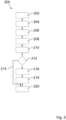
- FIG. 3 a flow chart is shown which shows an exemplary course of a braking process 200 using the method according to the invention for operating the safety braking device 32.
- the processing tool rotates in the initial situation 202.
- a method step 204 the approach of a user to the processing tool 28 is detected by means of the sensor 34 of the sensor device.
- the rotation of the output unit, in particular of the output shaft 26, is then braked, in particular stopped, at least substantially by means of the first braking stage 22 in method step 208 after activation of the braking process in method step 206.
- the sensor 34 detects a further approach of the user to the processing tool 28, in particular a touch of the processing tool 28 by the user is detected by means of the sensor 34.
- a query is then made in method step 212 as to whether the machining tool is already stationary. If this is the case, the braking process is terminated via the arrow 214, and the machining tool 28 is in the final state in 220. If, however, a rotation of the machining tool 28 is detected, in method step 218 the rotation of the output unit, in particular the output shaft 26, is at least substantially braked by means of the second braking stage 24, in particular stopped after the braking process was initiated in method step 216. This emergency braking process which now takes place by means of the second braking stage leads to the machining tool stopping in the final state 220.
Landscapes
- Engineering & Computer Science (AREA)
- Life Sciences & Earth Sciences (AREA)
- Mechanical Engineering (AREA)
- Wood Science & Technology (AREA)
- Forests & Forestry (AREA)
- Power Engineering (AREA)
- General Engineering & Computer Science (AREA)
- Auxiliary Devices For Machine Tools (AREA)
- Sawing (AREA)
- Braking Arrangements (AREA)
Description
- Die Erfindung betrifft eine Sicherheitsbremsvorrichtung für eine Werkzeugmaschine.
- Sicherheitsbremsvorrichtungen sind aus dem Stand der Technik bekannt, beispielsweise aus
DE 10 2008 054 694 A1 , oder dieDE 60 2004 005115 T2 , die die Basis für den Oberbegriff des Anspruchs 1 bildet. - Die Erfindung geht aus von einer Sicherheitsbremsvorrichtung für eine Werkzeugmaschine zum Bremsen eines mittels eines Elektromotors über eine Abtriebseinheit, insbesondere eine Abtriebswelle, angetriebenen, insbesondere rotierend angetriebenen, Bearbeitungswerkzeugs, aufweisend zumindest eine Bremsvorrichtung, die dazu vorgesehen ist, bei einem Bremsvorgang eine Rotation der Abtriebseinheit zu bremsen, insbesondere zu stoppen. Erfindungsgemäß weist die Bremsvorrichtung zumindest eine erste Bremsstufe und eine zweite Bremsstufe auf.
- Unter einer "Sicherheitsbremsvorrichtung" soll insbesondere eine Vorrichtung verstanden werden, die ein Bearbeitungswerkzeug in einer Situation, in der Gefahr von dem Bearbeitungswerkzeug für einen Benutzer besteht, mittels zumindest der Bremsvorrichtung bremst oder stoppt. Insbesondere bremst die Sicherheitsbremsvorrichtung das Bearbeitungswerkzeug bei einer Annäherung oder Berührung des Bearbeitungswerkzeugs durch einen Benutzer. Die Sicherheitsbremsvorrichtung kann als separate Einrichtung zur Verwendung in einer Werkzeugmaschine oder auch als Teil einer Steuervorrichtung einer Werkzeugmaschine realisiert sein. In einer Ausführungsform umfasst die Sicherheitsbremsvorrichtung ferner eine Recheneinheit und eine Sensoreinheit, wobei die Recheneinheit mit zumindest einem Sensor der Sensoreinheit kommuniziert. Der Sensor ist dazu vorgesehen, eine Gefahr für einen Benutzer, insbesondere eine Annäherung des Benutzers an das Bearbeitungswerkzeug und/oder eine Berührung des Bearbeitungswerkzeugs durch den Benutzer, zu detektieren. Entsprechend gibt die Sensorvorrichtung ein Detektionssignal an die Sicherheitsbremsvorrichtung aus. Eine Elektronik der Sicherheitsbremsvorrichtung, insbesondere die Recheneinheit, dient der Steuerung der Bremsvorrichtung. Insbesondere ist die Elektronik der Sicherheitsbremsvorrichtung, insbesondere die Recheneinheit, dazu vorgesehen, nach Detektion einer Annäherung des Benutzers an das Bearbeitungswerkzeug und/oder nach Detektion eines Kontakts des Benutzers mit dem Bearbeitungswerkzeug, einen Bremsvorgang zu initiieren, zu steuern und/oder zu regeln.
- Unter "vorgesehen" soll insbesondere speziell ausgestattet, ausgelegt und/oder programmiert verstanden werden.
- Unter einer "Werkzeugmaschine" soll eine prinzipiell beliebige Werkzeugmaschine verstanden werden, die ein mittels eines Elektromotors über eine Abtriebseinheit, insbesondere eine Abtriebswelle, angetriebenes, drehbar gelagertes Bearbeitungswerkzeug aufweist. Insbesondere kann die Werkzeugmaschine eine netzbetriebene oder eine kabellose, akkubetriebene Werkzeugmaschine sein. Das Bearbeitungswerkzeug kann insbesondere auch als Werkzeugaufnahme realisiert sein. Das Bearbeitungswerkzeug ist im Wesentlichen drehfest mit der Abtriebseinheit verbunden oder zumindest in einem Betriebszustand der Werkzeugmaschine im Wesentlichen drehfest mit der Abtriebseinheit verbindbar, beispielsweise über eine Werkzeugaufnahme, sodass ein Drehmoment von der Abtriebseinheit, insbesondere der Abtriebswelle, auf das Bearbeitungswerkzeug übertragbar ist. Unter "im Wesentlichen drehfest" ist an dieser Stelle zu verstehen, dass das Bearbeitungswerkzeug in einem Bremsvorgang gegenüber der Abtriebseinheit eine Relativrotation von weniger als 15°, insbesondere von weniger als 10°, ganz insbesondere von weniger al 5° vollführt. Unter einer "Abtriebseinheit" soll insbesondere eine Vorrichtung verstanden werden, die dazu vorgesehen ist, ein Drehmoment auf die Abtriebswelle zu übertragen. Beispielsweise kann die Abtriebseinheit als eine Getriebestufe ausgebildet sein. Das Drehmoment wird von dem Elektromotor, insbesondere einem bürstenlosen Gleichstrommotor (,brushless DC motor" (BLDC-Motor) oder ,electronically commutated motor" (EC-Motor)) oder alternativ einem AC-Motor (Universalmotor), erzeugt. Unter Verwendung eines EC-Motors kann ein direktantrieb der Abtriebseinheit, insbesondere der Abtriebswelle, ohne Zwischenschaltung eines Getriebes oder einer Kupplung realisiert werden. Derart kann vorteilhaft auf die Komponenten des Getriebes oder der Kupplung verzichtet werden, sodass eine kompaktere, leichtere und günstigere Werkzeugmaschine realisierbar ist. Ferner kann vorteilhaft eine während eines Bremsvorgangs abzubremsende Rotationsmasse und/oder Rotationsenergie der An- und/oder Abtriebseinheit reduziert werden und damit eine besonders kurze Zeit, bis das Bearbeitungswerkzeug zum Stillstand gebracht ist, erreicht werden. Es sei angemerkt, dass derartige Elektromotoren dem Fachmann bekannt sind. Die Abtriebseinheit, insbesondere eine Abtriebswelle, ermöglicht eine Rotation des Bearbeitungswerkzeugs durch Drehung zumindest der Abtriebswelle um ihre Längsachse. Beispiele derartiger Werkzeugmaschinen umfassen insbesondere Bohrmaschinen, Motorsensen, Rasenmäher, Kreissägen, Tischkreissägen, Kappsägen, Gehrungssägen oder andere dem Fachmann als sinnvoll erscheinende Werkzeugmaschinen. In einer Ausführungsform kann die Werkzeugmaschine als handgehaltene Handwerkzeugmaschine realisiert sein, beispielsweise als kabellose akkubetriebene Handkreissäge oder dergleichen. In einem Ausführungsbeispiel kann die Werkzeugmaschine als eine Handkreissäge mit einem mittels des Elektromotors über eine Abtriebswelle angetriebenen, als Kreissägeblatt ausgebildeten Bearbeitungswerkzeug und mit einer Sensorplatte, die eine Annährung eines Benutzers an das Kreissägeblatt sowie einen Kontakt eines Körperteils des Benutzers mit dem Bearbeitungswerkzeug erfasst, realisiert sein.
- Unter einer "Bremsvorrichtung" ist eine Vorrichtung zu verstehen, die der Abbremsung oder dem Stoppen der Rotation des Bearbeitungswerkzeugs im Falle der Detektion einer Annäherung oder Berührung des Bearbeitungswerkzeugs durch einen Benutzer dient. Unter "bremsen" ist insbesondere eine Reduzierung der Drehgeschwindigkeit bzw. Rotationsgeschwindigkeit des Bearbeitungswerkzeugs zu verstehen. Unter "stoppen" ist insbesondere zu verstehen, dass das Bearbeitungswerkzeug zumindest so stark abgebremst wird, dass eine verbleibende Umdrehungsfrequenz kleiner als 0,5 Hz, bevorzugt kleiner als 0,1 Hz beträgt. Bevorzugt bezeichnet "stoppen" das Erreichen des Stillstands des Bearbeitungswerkzeugs bezüglich dessen Rotationsbewegung. Der Stillstand kennzeichnet dabei das erstmalige Erreichen des Nullpunkts der Drehgeschwindigkeit der Abtriebswelle, unabhängig davon, ob anschließend noch eine (geringfügige) Rotation der Antriebswelle - beispielsweise auf Grund von Materialrelaxationseffekten - auftritt.
- Die Bremsvorrichtung ist als zumindest zweistufige Bremsvorrichtung realisiert.
- Die Bremsvorrichtung weist daher zumindest eine erste Bremsstufe und eine zweite Bremsstufe auf. Unter einer "Bremsstufe" ist insbesondere eine Implementierung der Sicherheitsvorrichtung zu verstehen, die eine für die Bremsstufe charakteristische Bremswirkung auf die Abtriebseinheit, insbesondere eine Abtriebswelle, ausübbar macht. Insbesondere kann eine Bremsstufe als ein Betriebsmodus oder Bremsmodus der Sicherheitsbremsvorrichtung verstanden werden. In einer Ausführungsform sind die erste Bremsstufe und die zweite Bremsstufe hinsichtlich einer in einem Bremsvorgang ausübbaren bzw. ausgeübten Bremswirkung unterschiedlich. So kann beispielsweise in einer Ausführungsform die erste Bremsstufe mit einer leichten Bremswirkung und die zweite Bremsstufe mit einer starken Bremswirkung realisiert sein.
- Erfindungsgemäß ist die Bremsvorrichtung dazu vorgesehen, in einem Bremsvorgang die erste Bremsstufe anzuwenden, sobald eine Annäherung eines Benutzers an das Bearbeitungswerkzeug durch die Sensorvorrichtung erkannt bzw. detektiert wird. In diesem Falle wird die Rotation der Abtriebseinheit im Wesentlichen mittels oder unter Anwendung der ersten Bremsstufe der Bremsvorrichtung gebremst, insbesondere gestoppt. Unter "im Wesentlichen" ist hier zu verstehen, dass die auf die Abtriebseinheit wirkende gesamte Bremswirkung zu mindestens 60 %, insbesondere zu mindestens 80 %, ganz insbesondere zu 100 % mittels oder unter Anwendung der ersten Bremsstufe erzeugbar ist bzw. erzeugt wird. Erfindungsgemäß ist die Bremsvorrichtung dazu vorgesehen, in einem Bremsvorgang die zweite Bremsstufe anzuwenden, sobald eine weitere Annäherung eines Benutzers an das Bearbeitungswerkzeug durch die Sensorvorrichtung erkannt bzw. detektiert wird oder insbesondere eine Berührung des Bearbeitungswerkzeugs durch ein Körperteil des Benutzers detektiert wird. In diesem Falle wird die Rotation der Abtriebseinheit im Wesentlichen mittels oder unter Anwendung der zweiten Bremsstufe der Bremsvorrichtung gebremst, insbesondere gestoppt. Unter "im Wesentlichen" ist hier zu verstehen, dass die auf die Abtriebseinheit wirkende gesamte Bremswirkung zu mindestens 60 %, insbesondere zu mindestens 80 %, ganz insbesondere zu 100 % mittels oder unter Anwendung der zweiten Bremsstufe erzeugbar ist bzw. erzeugt wird. Erfindungsgemäß kann somit eine zweistufige Bremsvorrichtung realisiert werden, bei der die erste Bremsstufe bereits für eine Abbremsung des Bearbeitungswerkzeugs und somit für eine Reduzierung der Rotationsenergie sorgt, sobald die Annäherung eines Benutzers an das Bearbeitungswerkzeug detektiert wird. Sollte der Benutzer mit einem Körperteil noch dichter an das Bearbeitungswerkzeug geraten oder dieses gar berühren, erfolgt ein Bremsvorgang (Notbremsvorgang), bei der die zweite Bremsstufe für eine besonders schnelle Abbremsung des rotierenden Bearbeitungswerkzeugs sorgt. Durch die vorgeschaltete erste Bremsstufe ist bis zur weiteren Annäherung oder gar Berührung des Bearbeitungswerkzeugs durch den Körperteil des Benutzers bereits ein Teil der ursprünglichen Rotationsenergie abgebaut. Somit ist folglich eine geringe verbleibende Rotationsenergie bis zu einem Stillstand des Bearbeitungswerkzeugs zu reduzieren, sodass ein schnellerer und sicherer Bremsvorgang erzielt werden kann. Ferner kann, insbesondere im Falle der Realisierung der zweiten Bremsstufe als mechanische Bremsstufe, eine geringe Beanspruchung der mechanischen Komponenten der Bremsstufe erzielt werden. Die zweite Bremsstufe wird somit langlebiger und/oder kann einfacher und kompakter ausgeführt werden. Ferner ist denkbar, dass in einem Bremsvorgang die zweite Bremsstufe nicht benötigt - da der Benutzer sich dem Bearbeitungswerkzeug nicht weiter annähert - und daher nicht zum Einsatz kommt. In diesem Falle kann, insbesondere im Falle der Realisierung der zweiten Bremsstufe als mechanische Bremsstufe, die Werkzeugmaschine einfacher wieder in Betrieb genommen werden, da beispielsweise insbesondere kein Zurücksetzen, Spannen, oder Tauschen von mechanischen Komponenten, insbesondere eines Aktorelements, erforderlich ist. Der Sensor zur Detektion einer Gefahr für einen Benutzer, insbesondere zur Detektion einer Annäherung des Benutzers an das Bearbeitungswerkzeug und/oder einer Berührung des Bearbeitungswerkzeugs durch den Benutzer, kann in einem Ausführungsbeispiel als ein kapazitiv messenden Sensor realisiert sein (beispielsweise mittels eines Wechselfelds). Bei einer Handkreissäge kann beispielsweise
neben dem Sägeblatt (Bearbeitungswerkzeug) eine Sensorplatte beabstandet vom Sägeblatt angeordnet sein, wobei die Sensorplatte dazu vorgesehen ist, eine Annäherung menschlicher Haut an das Sägeblatt und eine Berührung menschlicher Haut mit dem Sägeblatt zu unterscheiden und entsprechende Detektionssignale auszugeben. Insbesondere besitzt die Sensorplatte einen geringen Abstand zum Sägeblatt (von 1 bis 10 mm, insbesondere von 1,5 bis 3 mm, bevorzugt aber von 2 mm) und ist gegenüber dem Gehäuse der Handkreissäge elektrisch isoliert. Die Sensorplatte ist mit einer Elektronik der Handkreissäge elektrisch verbunden, wobei die Elektronik dazu vorgesehen ist, in Reaktion auf die Detektion einer Annäherung menschlicher Haut an das Sägeblatt und der Detektion einer Berührung menschlicher Haut mit dem Sägeblatt einen Bremsvorgang unter Verwendung der ersten Bremsstufe bzw. der zweiten Bremsstufe einzuleiten. Unter einer "weiteren Annäherung" ist insbesondere zu verstehen, dass der Abstand zwischen dem sich dem Bearbeitungswerkzeug nähernden Körperteil des Benutzers und dem Bearbeitungswerkzeug sich verringert. - Erfindungsgemäß ist die erste Bremsstufe der Bremsvorrichtung als elektronische Bremsstufe ausgebildet. Unter einer "elektronischen Bremsstufe" ist insbesondere zu verstehen, dass die Bremswirkung mittels elektronischer Komponenten der Sicherheitsbremsvorrichtung erzeugbar ist bzw. erzeugt wird. In einer Ausführungsform der Sicherheitsbremsvorrichtung ist die erste Bremsstufe der Bremsvorrichtung mittels einer Gegensteuerung des Elektromotors realisiert. Unter einer Gegensteuerung ist insbesondere ein Betrieb des Elektromotors unter Gegenpolung oder alternativ ein Kurzschluss der Windungen des Elektromotors zu verstehen. Derart kann mittels der Elektronik des Elektromotors dieser gebremst werden. Vorteilhaft verwendet die erste Bremsstufe zur Erzeugung einer Bremswirkung bereits in der Werkzeugmaschine vorgesehene Einrichtungen wie beispielsweise den Elektromotor. Derart kann eine besonders einfach und kostengünstig realisierbare und hinsichtlich ihrer Konstruktion besonders kompakte erste Bremsstufe realisiert werden.
- In einer Ausführungsform der Sicherheitsbremsvorrichtung ist die erste Bremsstufe der Bremsvorrichtung dazu vorgesehen, bei einem Bremsvorgang eine Rotation der Abtriebseinheit mindestens innerhalb von 1000 Millisekunden zu stoppen, insbesondere mindestens innerhalb von 500 Millisekunden zu stoppen, ganz insbesondere mindestens innerhalb von 200 Millisekunden zu stoppen. Derart kann sichergestellt werden, dass im Falle einer weiteren Annäherung des Benutzers an das rotierende Bearbeitungswerkzeug dieses entsprechend kurzfristig zum Stillstand gebracht wird, bevor der Benutzer das Bearbeitungswerkzeug berührt. Unter "stoppen" ist insbesondere zu verstehen, dass das Bearbeitungswerkzeug zumindest so stark abgebremst wird, dass eine verbleibende Umdrehungsfrequenz kleiner als 0,5 Hz, bevorzugt kleiner als 0,1 Hz beträgt. Bevorzugt bezeichnet "stoppen" das Erreichen des Stillstands des Bearbeitungswerkzeugs bezüglich dessen Rotationsbewegung. Der Stillstand kennzeichnet dabei das erstmalige Erreichen des Nullpunkts der Drehgeschwindigkeit der Abtriebswelle, unabhängig davon, ob anschließend noch eine (geringfügige) Rotation der Antriebswelle - beispielsweise auf Grund von Materialrelaxationseffekten - auftritt.
- Erfindungsgemäß ist die zweite Bremsstufe der Bremsvorrichtung als mechanische Bremsstufe mit zumindest einem mechanischen Bremselement ausgebildet. Dabei wird die Bremswirkung durch mechanisches Verzögern oder Blockieren der Rotation der Abtriebseinheit, insbesondere der Abtriebswelle, realisiert. Derart kann ein hoher Strom, wie er zur Erzeugung kurzer Bremszeiten unter Verwendung einer zweiten Bremsstufe basierend auf einer Gegensteuerung eines Elektromotors notwendig wäre, vorteilhaft vermieden werden. Derart hohe Ströme könnten zu einer Beschädigung der Elektronik und/oder des Elektromotors führen, die den Austausch des Elektromotors zur Folge hätten. Mittels der Realisierung der zweiten Bremsstufe als mechanische Bremsstufe kann daher vorteilhaft die Lebensdauer des Werkzeugs erhöht werden. In einem Ausführungsbeispiel kann die mechanische Bremsstufe beispielsweise durch eine zweiteilige Bremsvorrichtung realisiert sein, wobei ein erster Bremsvorrichtungsteil und ein zweiter Bremsvorrichtungsteil als komplementäre Bestandteile einer zumindest zweiteiligen Klauenkupplung (oder dazu äquivalent: Klauenbremse) ausgebildet sind, wobei der erste Bremsvorrichtungsteil und der zweite Bremsvorrichtungsteil jeweils zumindest ein Verzahnungselement aufweisen, die dazu vorgesehen sind, bei einem Bremsvorgang ineinander in Eingriff zu stehen und derart eine Rotation der Abtriebseinheit zu bremsen, insbesondere zu stoppen. Der erste Bremsvorrichtungsteil bildet dabei einen ersten Klauenkupplungsteil und der zweite Bremsvorrichtungsteil bildet dabei einen zweiten Klauenkupplungsteil. Unter einer "zweiteiligen Klauenkupplung" ist dabei eine Kupplung zu verstehen, die durch formschlüssige Kupplung funktioniert, indem Verzahnungselemente an den beiden Bremsvorrichtungsteilen miteinander in Eingriff gebracht werden und somit eine Momentübertragung in Folge einer Relativbewegung der beiden Bremsvorrichtungsteile zueinander, insbesondere in Folge einer Relativbewegung der beiden Bremsvorrichtungsteile in Rotationsrichtung zueinander, ermöglichen. Durch Realisierung der Sicherheitsbremsvorrichtung mittels einer Klauenkupplung kann eine formschlüssige Verbindung genutzt werden, um auf besonders schnelle und sichere Weise einen Bremsvorgang (Notbremsvorgang) durchzuführen. Der erste Bremsvorrichtungsteil ist in einer Ausführungsform auf der Abtriebseinheit, insbesondere auf der Abtriebswelle, im Wesentlichen drehfest angeordnet. Der zweite Bremsvorrichtungsteil ist dazu vorgesehen, im Wesentlichen drehfest mit einem anderen Bestandteil der Werkzeugmaschine, insbesondere beispielsweise einem Gehäuse, einem Getriebegehäuse, einem Motorgehäuse oder einer anderen Struktur der Werkzeugmaschine, verbunden zu sein und somit zumindest im Wesentlichen drehfest bezogen auf die Werkzeugmaschine angeordnet zu sein. In einer Ausführungsform kann der zweite Bremsvorrichtungsteil dazu vorgesehen sein, im Wesentlichen unbeweglich mit dem anderen Bestandteil der Werkzeugmaschine verbunden zu sein und somit nicht nur im Wesentlichen drehfest bezogen auf die Werkzeugmaschine angeordnet zu sein. In einem Ausführungsbeispiel ist der zweite Bremsvorrichtungsteil gegenüber einem Motorgehäuse der Werkzeugmaschine im Wesentlichen unbeweglich ausgeführt. Derart kann insbesondere eine freie Rotation des zweiten Bremsvorrichtungsteils bezüglich der Werkzeugmaschine und auch bezüglich der Abtriebseinheit, insbesondere bezüglich der Abtriebswelle, und somit bezüglich dem im Wesentlichen drehfest mit der Abtriebseinheit verbundenen ersten Bremsvorrichtungsteil unterbunden werden. Unter "im Wesentlichen drehfest" ist zu verstehen, dass ein jeweiliger Bremsvorrichtungsteil nicht wesentlich in Richtung des Umfangs der Abtriebseinheit, insbesondere der Abtriebswelle, verschiebbar (rotierbar) oder gleitend gelagert ist. Unter "der erste Bremsvorrichtungsteil ist im Wesentlichen drehfest auf der Abtriebseinheit angeordnet" ist zu verstehen, dass der erste Bremsvorrichtungsteil mit einer Drehbewegung der Abtriebseinheit, insbesondere der Abtriebswelle, mitdrehend mit der Abtriebseinheit, insbesondere der Abtriebswelle, verbunden ist, wobei durch "im Wesentlichen" eine maximale Relativbewegung von Abtriebseinheit, insbesondere Abtriebswelle, und erstem Bremsvorrichtungsteil zueinander zugelassen sein soll, die kleiner als 15°, insbesondere kleiner als 10°, ganz insbesondere kleiner als 5° ist. In einem Ausführungsbeispiel beträgt die maximal zulässige Relativbewegung des ersten Bremsvorrichtungsteils 12,5°. Insbesondere tritt diese Relativbewegung nur bei einem sehr großen anliegenden Drehmoment auf das erste Bremsvorrichtungsteil auf, wie es bei einem schlagartigen Bremsvorgang auftreten kann. Unter "der zweite Bremsvorrichtungsteil ist im Wesentlichen drehfest angeordnet, insbesondere bezogen auf die Werkzeugmaschine im Wesentlichen drehfest angeordnet" ist zu verstehen, dass eine maximale Relativbewegung von dem Bestandteil der Werkzeugmaschine, an dem das zweite Bremsvorrichtungsteil befestigt ist, und dem zweiten Bremsvorrichtungsteil zueinander zugelassen sein soll, die kleiner als 30°, insbesondere kleiner als 10°, ganz insbesondere kleiner als 5° ist. In einem Ausführungsbeispiel beträgt die maximal zulässige Relativbewegung des zweiten Bremsvorrichtungsteils 15°. Unter "Verzahnungselementen" sind konstruktiv bedingte Vorsprünge sowohl des ersten Bremsvorrichtungsteils als auch des zweiten Bremsvorrichtungsteils zu verstehen, die dazu vorgesehen sind, miteinander in Eingriff gebracht zu werden. Dabei bilden die Verzahnungselemente eines Bremsvorrichtungsteils gleichzeitig Verzahnungselemente des anderen Bremsvorrichtungsteils aufnehmende Ausnehmungen aus, sodass bei Interaktion der Bremsvorrichtungsteile Vorsprünge (Verzahnungselemente) und Ausnehmungen (Vertiefungen zwischen benachbarten Verzahnungselementen) komplementär zueinander angeordnete Paare bilden. Die Verzahnungselemente werden im Falle eines Bremsvorgangs derart miteinander in Eingriff gebracht, dass durch Momentübertragung zwischen dem an der Abtriebseinheit im Wesentlichen drehfest angeordneten (mitrotierenden) ersten Bremsvorrichtungsteil und dem gegenüber der Abtriebseinheit zumindest im Wesentlichen drehfest an der Werkzeugmaschine angeordneten zweiten Bremsvorrichtungsteil eine Momentübertragung erzeugbar ist, die der Rotationsbewegung des ersten Bremsvorrichtungsteils entgegenwirkt und derart die Rotation der Abtriebseinheit, insbesondere der Abtriebswelle, bremst, insbesondere stoppt oder blockiert. In einer Ausführungsform sind die Verzahnungselemente äquidistant und insbesondere derart am jeweiligen Bremsvorrichtungsteil vorgesehen, dass sie - bezogen auf die Drehachse der Abtriebseinheit, insbesondere der Abtriebswelle, drehsymmetrisch zu dieser angeordnet sind.
- Mittels einer mechanischen Bremsstufe kann ein besonders zuverlässiger Bremsvorgang mit besonders kurzen Bremszeiten ermöglicht werden. In einer Ausführungsform der Sicherheitsbremsvorrichtung ist die zweite Bremsstufe der Bremsvorrichtung dazu vorgesehen, bei einem Bremsvorgang eine Rotation der Abtriebseinheit mindestens innerhalb von 50 Millisekunden zu stoppen, insbesondere mindestens innerhalb von 20 Millisekunden zu stoppen, ganz insbesondere mindestens innerhalb von 5 Millisekunden zu stoppen. Unter "stoppen" ist insbesondere zu verstehen, dass das Bearbeitungswerkzeug zumindest so stark abgebremst wird, dass eine verbleibende Umdrehungsfrequenz kleiner als 0,5 Hz, bevorzugt kleiner als 0,1 Hz beträgt. Bevorzugt bezeichnet "stoppen" das Erreichen des Stillstands des Bearbeitungswerkzeugs bezüglich dessen Rotationsbewegung. Der Stillstand kennzeichnet dabei das erstmalige Erreichen des Nullpunkts der Drehgeschwindigkeit der Abtriebswelle, unabhängig davon, ob anschließend noch eine (geringfügige) Rotation der Antriebswelle - beispielsweise auf Grund von Materialrelaxationseffekten - auftritt.
- Ferner betrifft die Erfindung eine Werkzeugmaschine, insbesondere eine Handwerkzeugmaschine, insbesondere eine Handkreissäge mit einem als Kreissägeblatt ausgebildeten Bearbeitungswerkzeug, umfassend eine erfindungsgemäße Sicherheitsbremsvorrichtung. Auf diese Weise wird zum Abbremsen einer Bewegung, insbesondere einer Rotation, des Bearbeitungswerkzeugs eine besonders kurze Bremszeit, ermittelt zwischen einem Auslösen eines Bremsvorgangs bis zum Stoppen des Bearbeitungswerkzeugs, erreicht. Somit kann die Sicherheit eines Benutzers der Werkzeugmaschine deutlich erhöht werden. Insbesondere sind an die Situation, insbesondere an ein Verletzungsrisiko, angepasste adaptive Bremsvorgänge realisierbar, sodass auf ein stets drastisches Abbremsen verzichtet werden kann. Derart können die Komponenten der Sicherheitsbremsvorrichtung einfacher und kompakter realisiert werden und ferner länger eingesetzt werden, da eine Beanspruchung während der Durchführung eines Bremsvorgangs reduziert ist.
- In einem Ausführungsbeispiel der Werkzeugmaschine weist diese ferner eine Sensorplatte auf, die eine Annäherung oder Berührung des Bearbeitungswerkzeugs durch einen Benutzer, insbesondere einen Kontakt menschlicher Haut mit dem Bearbeitungswerkzeug, detektiert. Eine Elektronik der Werkzeugmaschine initiiert nach dem Detektieren einer Annäherung oder Berührung des Bearbeitungswerkzeugs durch einen Benutzer die Auslösung des Aktorelements, welches daraufhin einen Bremsvorgang auslöst. Das Aktorelement bewegt dabei aktiv den ersten Bremsvorrichtungsteil, um die beiden Bremsvorrichtungsteile bei einem Bremsvorgang miteinander in Eingriff zu bringen und derart eine Rotation der Abtriebseinheit, insbesondere der Abtriebswelle, zu bremsen, insbesondere zu stoppen. Gleichzeitigt bewirkt das Aktorelement durch die Bewegung des ersten Bremsvorrichtungsteils die Entkopplung der Abtriebseinheit von der Antriebseinheit.
- Ferner betrifft die Erfindung ein Verfahren zum Betreiben einer erfindungsgemäßen Sicherheitsbremsvorrichtung wie zuvor beschrieben, aufweisend zumindest eine Bremsvorrichtung, die dazu vorgesehen ist, bei einem Bremsvorgang eine Rotation der Abtriebseinheit zu bremsen, insbesondere zu stoppen, wobei die Bremsvorrichtung zumindest eine erste Bremsstufe und eine zweite Bremsstufe aufweist. Erfindungsgemäß wird in einem ersten Verfahrensschritt bei der Erkennung einer Annäherung eines Benutzers an das Bearbeitungswerkzeug die Rotation der Abtriebseinheit zumindest im Wesentlichen mittels der ersten Bremsstufe der Bremsvorrichtung gebremst, insbesondere gestoppt, und wird in einem zweiten Verfahrensschritt, insbesondere bei Erkennung einer weiteren Annäherung des Bearbeitungswerkzeugs durch den Benutzer oder bei Erkennung einer weiteren Annäherung des Benutzers an das Bearbeitungswerkzeug, insbesondere bei einer Berührung des Bearbeitungswerkzeugs durch den Benutzer, die Rotation der Abtriebseinheit zumindest im Wesentlichen mittels der zweiten Bremsstufe der Bremsvorrichtung gebremst, insbesondere gestoppt.
- Die Erfindung ist anhand von in den Zeichnungen dargestellten Ausführungsbeispielen in der nachfolgenden Beschreibung näher erläutert. Die Zeichnungen, die Beschreibung und die Ansprüche enthalten zahlreiche Merkmale in Kombination. Der Fachmann wird die Merkmale zweckmäßigerweise auch einzeln betrachten und zu sinnvollen weiteren Kombinationen zusammenfassen. Gleiche Bezugszeichen in den Figuren bezeichnen gleiche Elemente.
- Es zeigen:
- Figur 1:
- eine erfindungsgemäße Werkzeugmaschine in perspektivischer Darstellung,
- Figur 2:
- eine Schnittdarstellung durch Teile der Werkzeugmaschine samt erfindungsgemäßer Sicherheitsvorrichtung und Bremsvorrichtung in schematischer Darstellung,
- Figur 3:
- ein Ablaufdiagramm eines beispielhaften Bremsvorgangs.
-
Figur 1 zeigt eine erfindungsgemäße Werkzeugmaschine 10, realisiert als Handkreissäge 10a. Es sei darauf hingewiesen, dass die Ausführungen nicht auf eine Handkreissäge 10a beschränkt zu verstehen sind, sondern die den Ausführungen zu Grunde liegenden technischen Lehren prinzipiell auch auf beliebige andere, einem Fachmann sinnvoll erscheinende Werkzeugmaschinen, insbesondere beispielsweise Bohrmaschinen, Rasenmäher, Motorsensen oder dergleichen übertragbar sind. - Die Handkreissäge 10a umfasst ein erstes Gehäuse, welches als Motorgehäuse 12 ausgebildet ist, und ein zweites Gehäuse 14. Die Handkreissäge 10a weist einen Handgriff 16 und eine Grundplatte 18 zur Führung der Handkreissäge 10a auf. Die Handkreissäge 10a weist zu ihrer Energieversorgung einen Akkumulator (hier nicht näher dargestellt) auf. In einer alternativen oder zusätzlichen Ausführungsform der Handkreissäge 10a kann auch ein stromnetzabhängiger Betrieb der Handkreissäge 10a vorgesehen sein.
- Das Motorgehäuse 12 umschließt einen Innenraum, in dem zumindest ein bürstenloser Elektromotor 20 angeordnet ist. Wie in
Figur 2 dargestellt, treibt der Motor 20 über eine Abtriebswelle 26, die Teil einer Abtriebseinheit ist, ein Bearbeitungswerkzeug 28 (vgl.Figur 1 ) bei einem Arbeitsvorgang drehend an. Das Bearbeitungswerkzeug 28 ist hier als Sägeblatt, insbesondere als Kreissägeblatt, ausgebildet. Eine Sägeblattabdeckung 30 schützt vor einer Berührung des Bearbeitungswerkzeugs 28 und vor durch das Bearbeitungswerkzeug 28 ausgeschleuderte Werkstückspäne eines Werkstücks (vgl.Figur 1 ). - Eine Sicherheitsbremsvorrichtung 32 ist zum Bremsen des Bearbeitungswerkzeugs 28 vorgesehen, sobald eine Annäherung eines menschlichen Körperteils, wie beispielsweise einer Hand, mit einem Sensor 34 der Handkreissäge 10a detektiert wird. Der Sensor 34 ist in diesem Ausführungsbeispiel durch einen kapazitiv messenden Sensor realisiert. Der Sensor 34 ermöglicht eine Detektion eines sich dem Bearbeitungswerkzeug 28 nähernden Körperteils auf Grund kapazitiver Messungen (beispielsweise mittels eines Wechselfelds), wobei in Folge einer Detektion ein Detektionssignal erzeugt und an eine Steuervorrichtung der Handkreissäge 10a ausgegeben wird (Kabelverbindung in
Figur 2 zwischen Sensor 34 und Elektronik 102). Derartige Sensoren sind dem Fachmann bekannt. - Die Sicherheitsbremsvorrichtung 32 weist zumindest eine erste Bremsstufe 22 und eine zweite Bremsstufe 24 auf. Die erste Bremsstufe 22 und die zweite Bremsstufe 24 sind hinsichtlich einer in einem Bremsvorgang ausübbaren Bremswirkung unterschiedlich ausgestaltet. Die erste Bremsstufe 22 der Sicherheitsbremsvorrichtung 32 ist als elektronische Bremsstufe 22 ausgebildet, indem während eines Bremsvorgangs der bürstenlose Elektromotor 20 mittels einer Gegensteuerung betreibbar ist, sodass er als Motorbremse wirkt. Im diesem Falle übt der Elektromotor 20 eine der Rotation der Abtriebswelle 26 - und eine der Eigenrotation der Motorwelle - entgegen gerichtete Kraft auf die Abtriebswelle 26 aus und bremst diese somit ab. Dabei ist die derart realisierte erste Bremsstufe 22 prinzipiell dazu vorgesehen, bei einem Bremsvorgang eine Rotation der Abtriebswelle 26 mindestens innerhalb von 200 Millisekunden zu stoppen.
- Die zweite Bremsstufe 24 ist als mechanische Bremsstufe 24 mit zumindest einem mechanischen Bremselement ausgebildet. Wie dargestellt, ist die zweite Bremsstufe 24 als zumindest zweiteilige Klauenkupplung mit einem ersten Klauenkupplungsteil 44 (erster Bremsvorrichtungsteil) und einem zweiten Klauenkupplungsteil 46 (zweiter Bremsvorrichtungsteil) ausgebildet, wobei der erste Klauenkupplungsteil 44 auf der Abtriebswelle 26 im Wesentlichen drehfest und axial beweglich angeordnet ist. Der zweite Klauenkupplungsteil 46 ist im Wesentlichen drehfest, insbesondere im Wesentlichen unbeweglich, bezogen auf die Werkzeugmaschine, d.h. bezogen auf das Motorgehäuse 12, angeordnet. Der erste Klauenkupplungsteil 44 und der zweite Klauenkupplungsteil 46 weisen jeweils mehr als ein Verzahnungselement 48 auf, die dazu vorgesehen sind, bei einem Bremsvorgang ineinander in Eingriff zu stehen (hier nicht näher dargestellt) und derart eine Rotation der Abtriebswelle 26 zu bremsen, insbesondere zu stoppen. Bei einem Bremsvorgang mittels der zweiten Bremsstufe 24 wird das erste Klauenkupplungsteil 44 in Richtung des zweiten Klauenkupplungsteils 46 axial entlang der Abtriebswelle 26 bewegt (in Richtung 100). Durch die axiale Bewegung des ersten Klauenkupplungsteils 44 zu dem zweiten Klauenkupplungsteil 46 wird eine Kupplung von erstem Klauenkupplungsteil 44 und zweitem Klauenkupplungsteil 46 durchgeführt, d.h. die Kupplung wird geschlossen. Die Verzahnungselemente 48 des ersten Klauenkupplungsteils 44 und des zweiten Klauenkupplungsteils 46 greifen folglich ineinander und bilden einen Formschluss. Auf Grund des Formschlusses wirkt ein der Rotation der Abtriebswelle 26 entgegen gerichtetes Drehmoment zwischen erstem Klauenkupplungsteil 44 und zweitem Klauenkupplungsteil 46. Folglich wird die Rotation der Abtriebswelle 26 und des ersten Klauenkupplungsteils 44 gebremst, insbesondere gestoppt oder blockiert.
- Im Ausführungsbeispiel der
Figur 2 wird das erste Klauenkupplungsteil 44 mittels des Aktorelements 36 axial, d.h. in Richtung 100, bewegt. Das Aktorelement 36 ist hier als eine Hubeinheit ausgebildet, welche, ausgelöst durch einen Stromfluss durch die Hubeinheit, eine Hebelbewegung ausführt, wobei der erste Klauenkupplungsteil 44 in axialer Richtung 100 bewegt wird. Die Hebelbewegung findet in einer Zeit unter 5ms, insbesondere unter 1,5 ms, statt. - Die zweite Bremsstufe 24 ist hier prinzipiell dazu vorgesehen, bei einem Bremsvorgang eine Rotation der Abtriebswelle 26 innerhalb von 2 Millisekunden zu stoppen.
- In einem alternativen Ausführungsbeispiel, kann die zweite Bremsstufe 24 ebenfalls als elektronische Bremsstufe 24 ausgebildet sein, beispielsweise analog zur ersten Bremsstufe 22 (vgl. oben).
- In
Figur 3 ist ein Ablaufdiagramm dargestellt, das einen beispielhaften Verlauf eines Bremsvorgangs 200 unter Anwendung des erfindungsgemäßen Verfahrens zum Betreiben der Sicherheitsbremsvorrichtung 32 wiedergibt. Während des Betriebs der Werkzeugmaschine 10, insbesondere der Handkreissäge 10a, dreht das Bearbeitungswerkzeug in Ausgangssituation 202. In einem Verfahrensschritt 204 wird die Annäherung eines Benutzers an das Bearbeitungswerkzeug 28 mittels des Sensors 34 der Sensorvorrichtung detektiert. Daraufhin wird die Rotation der Abtriebseinheit, insbesondere der Abtriebswelle 26, zumindest im Wesentlichen mittels der ersten Bremsstufe 22 in Verfahrensschritt 208 nach Aktivierung des Bremsvorgangs in Verfahrensschritt 206 gebremst, insbesondere gestoppt. In Verfahrensschritt 210 detektiert der Sensor 34 eine weitere Annäherung des Benutzers an das Bearbeitungswerkzeug 28, insbesondere wird eine Berührung des Bearbeitungswerkzeugs 28 durch den Benutzer mittels des Sensors 34 detektiert. Daraufhin wird in Verfahrensschritt 212 eine Abfrage vorgenommen, ob das Bearbeitungswerkzeug bereits steht. Ist dies der Fall, wird der Bremsvorgang über den Pfeil 214 beendet, das Bearbeitungswerkzeug 28 steht im Endzustand in 220. Wird hingegen eine Rotation des Bearbeitungswerkzeugs 28 erkannt, wird in Verfahrensschritt 218 die Rotation der Abtriebseinheit, insbesondere der Abtriebswelle 26, zumindest im Wesentlichen mittels der zweiten Bremsstufe 24 gebremst, insbesondere gestoppt, nachdem in Verfahrensschritt 216 der Bremsvorgang eingeleitet wurde. Dieser nun erfolgende Notbremsvorgang mittels der zweiten Bremsstufe führt zum Stoppen des Bearbeitungswerkzeugs in Endzustand 220.
Claims (8)
- Sicherheitsbremsvorrichtung (32) für eine Werkzeugmaschine (10) zum Bremsen eines mittels eines Elektromotors (20) über eine Abtriebseinheit, insbesondere eine Abtriebswelle (26), angetriebenen Bearbeitungswerkzeugs (28), aufweisend zumindest eine Bremsvorrichtung, die dazu vorgesehen ist, bei einem Bremsvorgang eine Rotation der Abtriebseinheit zu bremsen, insbesondere zu stoppen, eine Sensorvorrichtung (34) und eine Recheneinheit, die Bremsvorrichtung zumindest eine erste Bremsstufe (22) und eine zweite Bremsstufe (24) aufweist, wobei die erste Bremsstufe (22) der Bremsvorrichtung als elektronische Bremsstufe ausgebildet ist, wobei die zweite Bremsstufe (24) der Bremsvorrichtung als mechanische Bremsstufe mit zumindest einem mechanischen Bremselement ausgebildet ist, wobei die Recheneinheit dazu vorgesehen ist, in einem Bremsvorgang die erste Bremsstufe (22) anzuwenden, sobald eine Annäherung eines Benutzers an das Bearbeitungswerkzeug (28) durch eine Sensorvorrichtung (34) erkannt bzw. detektiert wird, wobei in diesem Falle die Rotation der Abtriebseinheit im Wesentlichen mittels oder unter Anwendung der ersten Bremsstufe (22) der Bremsvorrichtung gebremst, insbesondere gestoppt wird, dadurch gekennzeichnet, dass die Bremsvorrichtung weiterhin dazu vorgesehen ist, in einem Bremsvorgang die zweite Bremsstufe (24) anzuwenden, sobald eine weitere Annäherung eines Benutzers an das Bearbeitungswerkzeug (28) durch die Sensorvorrichtung (34) erkannt bzw. detektiert wird oder insbesondere eine Berührung des Bearbeitungswerkzeugs (28) durch ein Körperteil des Benutzers detektiert wird, wobei in diesem Falle die Rotation der Abtriebseinheit im Wesentlichen mittels oder unter Anwendung der zweiten Bremsstufe (24) der Bremsvorrichtung gebremst, insbesondere gestoppt wird.
- Sicherheitsbremsvorrichtung (32) nach Anspruch 1, dadurch gekennzeichnet, dass die erste Bremsstufe (22) und die zweite Bremsstufe (24) hinsichtlich einer in einem Bremsvorgang ausübbaren Bremswirkung unterschiedlich sind.
- Sicherheitsbremsvorrichtung (32) nach einem der vorhergehenden Ansprüche, dadurch gekennzeichnet, dass die erste Bremsstufe (22) der Bremsvorrichtung mittels einer Gegensteuerung des Elektromotors realisiert ist.
- Sicherheitsbremsvorrichtung (32) nach einem der vorhergehenden Ansprüche, dadurch gekennzeichnet, dass die erste Bremsstufe (22) der Bremsvorrichtung dazu vorgesehen ist, bei einem Bremsvorgang eine Rotation der Abtriebseinheit mindestens innerhalb von 1000 Millisekunden zu stoppen, insbesondere mindestens innerhalb von 500 Millisekunden zu stoppen, ganz insbesondere mindestens innerhalb von 200 Millisekunden zu stoppen.
- Sicherheitsbremsvorrichtung (32) nach einem der vorhergehenden Ansprüche, dadurch gekennzeichnet, dass die zweite Bremsstufe (24) der Bremsvorrichtung dazu vorgesehen ist, bei einem Bremsvorgang eine Rotation der Abtriebseinheit mindestens innerhalb von 50 Millisekunden zu stoppen, insbesondere mindestens innerhalb von 20 Millisekunden zu stoppen, ganz insbesondere mindestens innerhalb von 5 Millisekunden zu stoppen.
- Sicherheitsbremsvorrichtung (32) nach einem der vorhergehenden Ansprüche, dadurch gekennzeichnet, dass die Bremsvorrichtung dazu vorgesehen, in einem Bremsvorgang zunächst die erste Bremsstufe (22) anzuwenden, falls eine Annäherung eines Benutzers an das Bearbeitungswerkzeug (28) detektiert wird, und die zweite Bremsstufe (24) anzuwenden, falls eine weitere Annäherung des Benutzers an das Bearbeitungswerkzeug (28) oder eine Berührung des Bearbeitungswerkzeugs (28) durch ein Körperteil des Benutzers detektiert wird.
- Werkzeugmaschine (10), insbesondere Handwerkzeugmaschine (10a), mit einer Sicherheitsbremsvorrichtung (32) nach einem der vorhergehenden Ansprüche.
- Verfahren zum Betreiben einer Sicherheitsbremsvorrichtung (32) nach einem der Ansprüche 1-6 aufweisend zumindest eine Bremsvorrichtung, die dazu vorgesehen ist, bei einem Bremsvorgang eine Rotation der Abtriebseinheit zu bremsen, insbesondere zu stoppen, wobei die Bremsvorrichtung zumindest eine erste Bremsstufe (22) und eine zweite Bremsstufe (24) aufweist, wobei in einem ersten Verfahrensschritt bei der Erkennung einer Annäherung eines Benutzers an das Bearbeitungswerkzeug (28) die Rotation der Abtriebseinheit zumindest im Wesentlichen mittels der ersten Bremsstufe (22) der Bremsvorrichtung gebremst, insbesondere gestoppt, wird, und in einem zweiten Verfahrensschritt, insbesondere bei Erkennung einer weiteren Annäherung des Benutzers an das Bearbeitungswerkzeug (28), insbesondere bei einer Berührung des Bearbeitungswerkzeugs (28) durch den Benutzer, die Rotation der Abtriebseinheit zumindest im Wesentlichen mittels der zweiten Bremsstufe (24) der Bremsvorrichtung gebremst, insbesondere gestoppt, wird.
Applications Claiming Priority (2)
| Application Number | Priority Date | Filing Date | Title |
|---|---|---|---|
| DE102018218725.8A DE102018218725A1 (de) | 2018-10-31 | 2018-10-31 | Sicherheitsbremsvorrichtung |
| PCT/EP2019/077005 WO2020088883A1 (de) | 2018-10-31 | 2019-10-07 | Sicherheitsbremsvorrichtung mit zwei bremsstufen |
Publications (2)
| Publication Number | Publication Date |
|---|---|
| EP3873697A1 EP3873697A1 (de) | 2021-09-08 |
| EP3873697B1 true EP3873697B1 (de) | 2024-09-04 |
Family
ID=68172203
Family Applications (1)
| Application Number | Title | Priority Date | Filing Date |
|---|---|---|---|
| EP19784034.1A Active EP3873697B1 (de) | 2018-10-31 | 2019-10-07 | Sicherheitsbremsvorrichtung mit zwei bremsstufen |
Country Status (5)
| Country | Link |
|---|---|
| US (1) | US12375012B2 (de) |
| EP (1) | EP3873697B1 (de) |
| CN (1) | CN112996629A (de) |
| DE (1) | DE102018218725A1 (de) |
| WO (1) | WO2020088883A1 (de) |
Families Citing this family (2)
| Publication number | Priority date | Publication date | Assignee | Title |
|---|---|---|---|---|
| DE102019208438A1 (de) * | 2019-06-11 | 2020-12-17 | Festool Gmbh | Werkzeugvorrichtung und Verfahren |
| US12278577B2 (en) * | 2021-05-13 | 2025-04-15 | Black & Decker Inc. | Power tool battery pack |
Citations (1)
| Publication number | Priority date | Publication date | Assignee | Title |
|---|---|---|---|---|
| DE602004005115T2 (de) * | 2003-09-12 | 2007-11-08 | Makita Corp., Anjo | Kraftwerkzeug |
Family Cites Families (16)
| Publication number | Priority date | Publication date | Assignee | Title |
|---|---|---|---|---|
| AU5847496A (en) * | 1995-05-24 | 1996-12-11 | New Zealand Logging Industry Research Association Incorporated, The | Improvements in safety equipment for motor driven saws |
| JPH11512803A (ja) * | 1995-09-25 | 1999-11-02 | セレンセン,イェルン | 第1物体と第2物体の間の距離を検知する方法及び装置 |
| DE19809939A1 (de) | 1998-03-07 | 1999-09-09 | Fein C & E | Gebremstes Elektrowerkzeug |
| US7055417B1 (en) * | 1999-10-01 | 2006-06-06 | Sd3, Llc | Safety system for power equipment |
| EP1234285B1 (de) | 1999-10-01 | 2016-06-15 | Sd3, Llc | Tischsäge mit Schutzsystem |
| US20060101960A1 (en) * | 2003-03-10 | 2006-05-18 | Smith Matthew A | Optical proximity device for power tools |
| JP4505193B2 (ja) * | 2003-04-16 | 2010-07-21 | 株式会社マキタ | チェーンソー |
| DE10317636A1 (de) * | 2003-04-17 | 2004-11-25 | Robert Bosch Gmbh | Bremseinrichtung für einen Elektromotor |
| DE102007044801A1 (de) | 2007-09-20 | 2009-04-09 | Robert Bosch Gmbh | Werkzeugmaschine |
| DE102008054694A1 (de) | 2008-12-16 | 2010-06-17 | Robert Bosch Gmbh | Werkzeugnotbremsvorrichtung |
| DE102010030077A1 (de) | 2010-06-15 | 2011-12-15 | Hilti Aktiengesellschaft | Eintreibvorrichtung |
| US9062827B2 (en) * | 2012-09-28 | 2015-06-23 | Robert Bosch Gmbh | Proximity based thermal profiling for a power tool |
| US9381664B2 (en) * | 2013-03-14 | 2016-07-05 | Robert Bosch Gmbh | Rotating saw with balanced dynamic braking |
| DE102014209009A1 (de) | 2014-01-27 | 2015-07-30 | Robert Bosch Gmbh | Werkzeugmaschinenvorrichtung |
| TWI730281B (zh) * | 2018-01-03 | 2021-06-11 | 美商米沃奇電子工具公司 | 電動工具中之電子制動技術 |
| JP7476014B2 (ja) | 2020-03-18 | 2024-04-30 | 株式会社マキタ | 石工用携帯用切断機 |
-
2018
- 2018-10-31 DE DE102018218725.8A patent/DE102018218725A1/de not_active Withdrawn
-
2019
- 2019-10-07 CN CN201980072563.2A patent/CN112996629A/zh active Pending
- 2019-10-07 US US17/289,019 patent/US12375012B2/en active Active
- 2019-10-07 EP EP19784034.1A patent/EP3873697B1/de active Active
- 2019-10-07 WO PCT/EP2019/077005 patent/WO2020088883A1/de not_active Ceased
Patent Citations (1)
| Publication number | Priority date | Publication date | Assignee | Title |
|---|---|---|---|---|
| DE602004005115T2 (de) * | 2003-09-12 | 2007-11-08 | Makita Corp., Anjo | Kraftwerkzeug |
Also Published As
| Publication number | Publication date |
|---|---|
| CN112996629A (zh) | 2021-06-18 |
| WO2020088883A1 (de) | 2020-05-07 |
| DE102018218725A1 (de) | 2020-04-30 |
| EP3873697A1 (de) | 2021-09-08 |
| US20220001504A1 (en) | 2022-01-06 |
| US12375012B2 (en) | 2025-07-29 |
Similar Documents
| Publication | Publication Date | Title |
|---|---|---|
| DE102018216573A1 (de) | Sicherheitsbremsvorrichtung | |
| DE102014219392A1 (de) | Sensorvorrichtung, insbesondere Handwerkzeugmaschinensensorvorrichtung | |
| WO2009138141A1 (de) | Werkzeugmaschine | |
| WO2022157037A1 (de) | Formatkreissäge mit sicherheitseinrichtung zur vermeidung von schnittverletzungen | |
| EP3362226A1 (de) | Handwerkzeugmaschine | |
| DE10317636A1 (de) | Bremseinrichtung für einen Elektromotor | |
| EP4061581B1 (de) | Verfahren zum betreiben einer werkzeugmaschine und werkzeugmaschine | |
| EP3873697A1 (de) | Sicherheitsbremsvorrichtung mit zwei bremsstufen | |
| EP3363598B1 (de) | Verfahren zum abbremsen einer werkzeugspindel | |
| DE112017003388T5 (de) | Übertragen von Drehmoment und Drehung über einen Isolator für eine Tischsäge | |
| EP2174055B1 (de) | Gerätesicherungsvorrichtung | |
| EP3263288B1 (de) | Handwerkzeugmaschine | |
| DE102011007403A1 (de) | Handgeführte Werkzeugmaschine | |
| WO2022069495A1 (de) | Bearbeitungsmaschine und verfahren zum betreiben einer bearbeitungsmaschine | |
| EP1907172B1 (de) | Elektrowerkzeug, insbesondere akkubetriebene gewindeschneidmaschine | |
| EP1990697B1 (de) | Verfahren zur Kolisionserkennung | |
| DE4446157C2 (de) | Elektrisch angetriebenes Gerät, insbesondere Handwerkzeug | |
| DE102012215457A1 (de) | Werkzeugmaschine | |
| DE102018216572A1 (de) | Sicherheitsbremsvorrichtung | |
| WO1996022175A2 (de) | Sicherheitseinrichtung für elektrisch angetriebene handwerkzeuge, insbesondere stich- und kreissägen | |
| DE102018216577A1 (de) | Sicherheitsbremsvorrichtung | |
| DE963205C (de) | Antrieb fuer Arbeitsmaschinen, insbesondere fuer die Fraesspindel von Fraesmaschinen | |
| DE102017213424A1 (de) | Handwerkzeugmaschine | |
| DE102007026517A1 (de) | Schnelldrehende Bearbeitungsmaschine | |
| DE102021201971A1 (de) | Bearbeitungsvorrichtung für eine drehende Bearbeitung |
Legal Events
| Date | Code | Title | Description |
|---|---|---|---|
| STAA | Information on the status of an ep patent application or granted ep patent |
Free format text: STATUS: UNKNOWN |
|
| STAA | Information on the status of an ep patent application or granted ep patent |
Free format text: STATUS: THE INTERNATIONAL PUBLICATION HAS BEEN MADE |
|
| PUAI | Public reference made under article 153(3) epc to a published international application that has entered the european phase |
Free format text: ORIGINAL CODE: 0009012 |
|
| STAA | Information on the status of an ep patent application or granted ep patent |
Free format text: STATUS: REQUEST FOR EXAMINATION WAS MADE |
|
| 17P | Request for examination filed |
Effective date: 20210531 |
|
| AK | Designated contracting states |
Kind code of ref document: A1 Designated state(s): AL AT BE BG CH CY CZ DE DK EE ES FI FR GB GR HR HU IE IS IT LI LT LU LV MC MK MT NL NO PL PT RO RS SE SI SK SM TR |
|
| DAV | Request for validation of the european patent (deleted) | ||
| DAX | Request for extension of the european patent (deleted) | ||
| GRAP | Despatch of communication of intention to grant a patent |
Free format text: ORIGINAL CODE: EPIDOSNIGR1 |
|
| STAA | Information on the status of an ep patent application or granted ep patent |
Free format text: STATUS: GRANT OF PATENT IS INTENDED |
|
| INTG | Intention to grant announced |
Effective date: 20240326 |
|
| GRAS | Grant fee paid |
Free format text: ORIGINAL CODE: EPIDOSNIGR3 |
|
| GRAA | (expected) grant |
Free format text: ORIGINAL CODE: 0009210 |
|
| STAA | Information on the status of an ep patent application or granted ep patent |
Free format text: STATUS: THE PATENT HAS BEEN GRANTED |
|
| AK | Designated contracting states |
Kind code of ref document: B1 Designated state(s): AL AT BE BG CH CY CZ DE DK EE ES FI FR GB GR HR HU IE IS IT LI LT LU LV MC MK MT NL NO PL PT RO RS SE SI SK SM TR |
|
| REG | Reference to a national code |
Ref country code: GB Ref legal event code: FG4D Free format text: NOT ENGLISH |
|
| REG | Reference to a national code |
Ref country code: CH Ref legal event code: EP |
|
| REG | Reference to a national code |
Ref country code: IE Ref legal event code: FG4D Free format text: LANGUAGE OF EP DOCUMENT: GERMAN |
|
| REG | Reference to a national code |
Ref country code: DE Ref legal event code: R096 Ref document number: 502019012063 Country of ref document: DE |
|
| REG | Reference to a national code |
Ref country code: LT Ref legal event code: MG9D |
|
| REG | Reference to a national code |
Ref country code: NL Ref legal event code: MP Effective date: 20240904 |
|
| PG25 | Lapsed in a contracting state [announced via postgrant information from national office to epo] |
Ref country code: NO Free format text: LAPSE BECAUSE OF FAILURE TO SUBMIT A TRANSLATION OF THE DESCRIPTION OR TO PAY THE FEE WITHIN THE PRESCRIBED TIME-LIMIT Effective date: 20241204 |
|
| PG25 | Lapsed in a contracting state [announced via postgrant information from national office to epo] |
Ref country code: FI Free format text: LAPSE BECAUSE OF FAILURE TO SUBMIT A TRANSLATION OF THE DESCRIPTION OR TO PAY THE FEE WITHIN THE PRESCRIBED TIME-LIMIT Effective date: 20240904 Ref country code: GR Free format text: LAPSE BECAUSE OF FAILURE TO SUBMIT A TRANSLATION OF THE DESCRIPTION OR TO PAY THE FEE WITHIN THE PRESCRIBED TIME-LIMIT Effective date: 20241205 Ref country code: PL Free format text: LAPSE BECAUSE OF FAILURE TO SUBMIT A TRANSLATION OF THE DESCRIPTION OR TO PAY THE FEE WITHIN THE PRESCRIBED TIME-LIMIT Effective date: 20240904 |
|
| PG25 | Lapsed in a contracting state [announced via postgrant information from national office to epo] |
Ref country code: BG Free format text: LAPSE BECAUSE OF FAILURE TO SUBMIT A TRANSLATION OF THE DESCRIPTION OR TO PAY THE FEE WITHIN THE PRESCRIBED TIME-LIMIT Effective date: 20240904 |
|
| PG25 | Lapsed in a contracting state [announced via postgrant information from national office to epo] |
Ref country code: LV Free format text: LAPSE BECAUSE OF FAILURE TO SUBMIT A TRANSLATION OF THE DESCRIPTION OR TO PAY THE FEE WITHIN THE PRESCRIBED TIME-LIMIT Effective date: 20240904 |
|
| PG25 | Lapsed in a contracting state [announced via postgrant information from national office to epo] |
Ref country code: HR Free format text: LAPSE BECAUSE OF FAILURE TO SUBMIT A TRANSLATION OF THE DESCRIPTION OR TO PAY THE FEE WITHIN THE PRESCRIBED TIME-LIMIT Effective date: 20240904 |
|
| PG25 | Lapsed in a contracting state [announced via postgrant information from national office to epo] |
Ref country code: ES Free format text: LAPSE BECAUSE OF FAILURE TO SUBMIT A TRANSLATION OF THE DESCRIPTION OR TO PAY THE FEE WITHIN THE PRESCRIBED TIME-LIMIT Effective date: 20240904 Ref country code: RS Free format text: LAPSE BECAUSE OF FAILURE TO SUBMIT A TRANSLATION OF THE DESCRIPTION OR TO PAY THE FEE WITHIN THE PRESCRIBED TIME-LIMIT Effective date: 20241204 |
|
| PG25 | Lapsed in a contracting state [announced via postgrant information from national office to epo] |
Ref country code: RS Free format text: LAPSE BECAUSE OF FAILURE TO SUBMIT A TRANSLATION OF THE DESCRIPTION OR TO PAY THE FEE WITHIN THE PRESCRIBED TIME-LIMIT Effective date: 20241204 Ref country code: PL Free format text: LAPSE BECAUSE OF FAILURE TO SUBMIT A TRANSLATION OF THE DESCRIPTION OR TO PAY THE FEE WITHIN THE PRESCRIBED TIME-LIMIT Effective date: 20240904 Ref country code: NO Free format text: LAPSE BECAUSE OF FAILURE TO SUBMIT A TRANSLATION OF THE DESCRIPTION OR TO PAY THE FEE WITHIN THE PRESCRIBED TIME-LIMIT Effective date: 20241204 Ref country code: LV Free format text: LAPSE BECAUSE OF FAILURE TO SUBMIT A TRANSLATION OF THE DESCRIPTION OR TO PAY THE FEE WITHIN THE PRESCRIBED TIME-LIMIT Effective date: 20240904 Ref country code: HR Free format text: LAPSE BECAUSE OF FAILURE TO SUBMIT A TRANSLATION OF THE DESCRIPTION OR TO PAY THE FEE WITHIN THE PRESCRIBED TIME-LIMIT Effective date: 20240904 Ref country code: GR Free format text: LAPSE BECAUSE OF FAILURE TO SUBMIT A TRANSLATION OF THE DESCRIPTION OR TO PAY THE FEE WITHIN THE PRESCRIBED TIME-LIMIT Effective date: 20241205 Ref country code: FI Free format text: LAPSE BECAUSE OF FAILURE TO SUBMIT A TRANSLATION OF THE DESCRIPTION OR TO PAY THE FEE WITHIN THE PRESCRIBED TIME-LIMIT Effective date: 20240904 Ref country code: ES Free format text: LAPSE BECAUSE OF FAILURE TO SUBMIT A TRANSLATION OF THE DESCRIPTION OR TO PAY THE FEE WITHIN THE PRESCRIBED TIME-LIMIT Effective date: 20240904 Ref country code: BG Free format text: LAPSE BECAUSE OF FAILURE TO SUBMIT A TRANSLATION OF THE DESCRIPTION OR TO PAY THE FEE WITHIN THE PRESCRIBED TIME-LIMIT Effective date: 20240904 |
|
| PG25 | Lapsed in a contracting state [announced via postgrant information from national office to epo] |
Ref country code: NL Free format text: LAPSE BECAUSE OF FAILURE TO SUBMIT A TRANSLATION OF THE DESCRIPTION OR TO PAY THE FEE WITHIN THE PRESCRIBED TIME-LIMIT Effective date: 20240904 |
|
| PG25 | Lapsed in a contracting state [announced via postgrant information from national office to epo] |
Ref country code: PT Free format text: LAPSE BECAUSE OF FAILURE TO SUBMIT A TRANSLATION OF THE DESCRIPTION OR TO PAY THE FEE WITHIN THE PRESCRIBED TIME-LIMIT Effective date: 20250106 Ref country code: IS Free format text: LAPSE BECAUSE OF FAILURE TO SUBMIT A TRANSLATION OF THE DESCRIPTION OR TO PAY THE FEE WITHIN THE PRESCRIBED TIME-LIMIT Effective date: 20250104 |
|
| PG25 | Lapsed in a contracting state [announced via postgrant information from national office to epo] |
Ref country code: SM Free format text: LAPSE BECAUSE OF FAILURE TO SUBMIT A TRANSLATION OF THE DESCRIPTION OR TO PAY THE FEE WITHIN THE PRESCRIBED TIME-LIMIT Effective date: 20240904 Ref country code: RO Free format text: LAPSE BECAUSE OF FAILURE TO SUBMIT A TRANSLATION OF THE DESCRIPTION OR TO PAY THE FEE WITHIN THE PRESCRIBED TIME-LIMIT Effective date: 20240904 |
|
| PG25 | Lapsed in a contracting state [announced via postgrant information from national office to epo] |
Ref country code: EE Free format text: LAPSE BECAUSE OF FAILURE TO SUBMIT A TRANSLATION OF THE DESCRIPTION OR TO PAY THE FEE WITHIN THE PRESCRIBED TIME-LIMIT Effective date: 20240904 |
|
| PG25 | Lapsed in a contracting state [announced via postgrant information from national office to epo] |
Ref country code: CZ Free format text: LAPSE BECAUSE OF FAILURE TO SUBMIT A TRANSLATION OF THE DESCRIPTION OR TO PAY THE FEE WITHIN THE PRESCRIBED TIME-LIMIT Effective date: 20240904 |
|
| PG25 | Lapsed in a contracting state [announced via postgrant information from national office to epo] |
Ref country code: SK Free format text: LAPSE BECAUSE OF FAILURE TO SUBMIT A TRANSLATION OF THE DESCRIPTION OR TO PAY THE FEE WITHIN THE PRESCRIBED TIME-LIMIT Effective date: 20240904 Ref country code: IT Free format text: LAPSE BECAUSE OF FAILURE TO SUBMIT A TRANSLATION OF THE DESCRIPTION OR TO PAY THE FEE WITHIN THE PRESCRIBED TIME-LIMIT Effective date: 20240904 |
|
| REG | Reference to a national code |
Ref country code: CH Ref legal event code: PL |
|
| REG | Reference to a national code |
Ref country code: DE Ref legal event code: R097 Ref document number: 502019012063 Country of ref document: DE |
|
| PG25 | Lapsed in a contracting state [announced via postgrant information from national office to epo] |
Ref country code: MC Free format text: LAPSE BECAUSE OF FAILURE TO SUBMIT A TRANSLATION OF THE DESCRIPTION OR TO PAY THE FEE WITHIN THE PRESCRIBED TIME-LIMIT Effective date: 20240904 |
|
| PG25 | Lapsed in a contracting state [announced via postgrant information from national office to epo] |
Ref country code: DK Free format text: LAPSE BECAUSE OF FAILURE TO SUBMIT A TRANSLATION OF THE DESCRIPTION OR TO PAY THE FEE WITHIN THE PRESCRIBED TIME-LIMIT Effective date: 20240904 |
|
| PLBE | No opposition filed within time limit |
Free format text: ORIGINAL CODE: 0009261 |
|
| STAA | Information on the status of an ep patent application or granted ep patent |
Free format text: STATUS: NO OPPOSITION FILED WITHIN TIME LIMIT |
|
| PG25 | Lapsed in a contracting state [announced via postgrant information from national office to epo] |
Ref country code: LU Free format text: LAPSE BECAUSE OF NON-PAYMENT OF DUE FEES Effective date: 20241007 Ref country code: BE Free format text: LAPSE BECAUSE OF NON-PAYMENT OF DUE FEES Effective date: 20241031 |
|
| PG25 | Lapsed in a contracting state [announced via postgrant information from national office to epo] |
Ref country code: CH Free format text: LAPSE BECAUSE OF NON-PAYMENT OF DUE FEES Effective date: 20241031 |
|
| REG | Reference to a national code |
Ref country code: BE Ref legal event code: MM Effective date: 20241031 |
|
| 26N | No opposition filed |
Effective date: 20250605 |
|
| PG25 | Lapsed in a contracting state [announced via postgrant information from national office to epo] |
Ref country code: SE Free format text: LAPSE BECAUSE OF FAILURE TO SUBMIT A TRANSLATION OF THE DESCRIPTION OR TO PAY THE FEE WITHIN THE PRESCRIBED TIME-LIMIT Effective date: 20240904 |
|
| PG25 | Lapsed in a contracting state [announced via postgrant information from national office to epo] |
Ref country code: IE Free format text: LAPSE BECAUSE OF NON-PAYMENT OF DUE FEES Effective date: 20241007 |
|
| REG | Reference to a national code |
Ref country code: AT Ref legal event code: MM01 Ref document number: 1719856 Country of ref document: AT Kind code of ref document: T Effective date: 20241007 |
|
| PGFP | Annual fee paid to national office [announced via postgrant information from national office to epo] |
Ref country code: DE Payment date: 20251209 Year of fee payment: 7 |
|
| PGFP | Annual fee paid to national office [announced via postgrant information from national office to epo] |
Ref country code: GB Payment date: 20251024 Year of fee payment: 7 |
|
| PG25 | Lapsed in a contracting state [announced via postgrant information from national office to epo] |
Ref country code: AT Free format text: LAPSE BECAUSE OF NON-PAYMENT OF DUE FEES Effective date: 20241007 |
|
| PGFP | Annual fee paid to national office [announced via postgrant information from national office to epo] |
Ref country code: FR Payment date: 20251027 Year of fee payment: 7 |
|
| PG25 | Lapsed in a contracting state [announced via postgrant information from national office to epo] |
Ref country code: CY Free format text: LAPSE BECAUSE OF FAILURE TO SUBMIT A TRANSLATION OF THE DESCRIPTION OR TO PAY THE FEE WITHIN THE PRESCRIBED TIME-LIMIT; INVALID AB INITIO Effective date: 20191007 |
|
| PG25 | Lapsed in a contracting state [announced via postgrant information from national office to epo] |
Ref country code: HU Free format text: LAPSE BECAUSE OF FAILURE TO SUBMIT A TRANSLATION OF THE DESCRIPTION OR TO PAY THE FEE WITHIN THE PRESCRIBED TIME-LIMIT; INVALID AB INITIO Effective date: 20191007 |
|
| PG25 | Lapsed in a contracting state [announced via postgrant information from national office to epo] |
Ref country code: TR Free format text: LAPSE BECAUSE OF FAILURE TO SUBMIT A TRANSLATION OF THE DESCRIPTION OR TO PAY THE FEE WITHIN THE PRESCRIBED TIME-LIMIT Effective date: 20240904 |
|
| PG25 | Lapsed in a contracting state [announced via postgrant information from national office to epo] |
Ref country code: SI Free format text: LAPSE BECAUSE OF FAILURE TO SUBMIT A TRANSLATION OF THE DESCRIPTION OR TO PAY THE FEE WITHIN THE PRESCRIBED TIME-LIMIT Effective date: 20240904 |
|
| PG25 | Lapsed in a contracting state [announced via postgrant information from national office to epo] |
Ref country code: LT Free format text: LAPSE BECAUSE OF FAILURE TO SUBMIT A TRANSLATION OF THE DESCRIPTION OR TO PAY THE FEE WITHIN THE PRESCRIBED TIME-LIMIT Effective date: 20240904 |