EP3873085A1 - Hochauflösende weitwinkel-entfernungsmesseinrichtung - Google Patents
Hochauflösende weitwinkel-entfernungsmesseinrichtung Download PDFInfo
- Publication number
- EP3873085A1 EP3873085A1 EP20783192.6A EP20783192A EP3873085A1 EP 3873085 A1 EP3873085 A1 EP 3873085A1 EP 20783192 A EP20783192 A EP 20783192A EP 3873085 A1 EP3873085 A1 EP 3873085A1
- Authority
- EP
- European Patent Office
- Prior art keywords
- resolution
- image sensor
- wide
- camera
- correction lens
- Prior art date
- Legal status (The legal status is an assumption and is not a legal conclusion. Google has not performed a legal analysis and makes no representation as to the accuracy of the status listed.)
- Pending
Links
Images


Classifications
-
- G—PHYSICS
- G02—OPTICS
- G02B—OPTICAL ELEMENTS, SYSTEMS OR APPARATUS
- G02B27/00—Optical systems or apparatus not provided for by any of the groups G02B1/00 - G02B26/00, G02B30/00
- G02B27/0025—Optical systems or apparatus not provided for by any of the groups G02B1/00 - G02B26/00, G02B30/00 for optical correction, e.g. distorsion, aberration
-
- H—ELECTRICITY
- H04—ELECTRIC COMMUNICATION TECHNIQUE
- H04N—PICTORIAL COMMUNICATION, e.g. TELEVISION
- H04N5/00—Details of television systems
- H04N5/222—Studio circuitry; Studio devices; Studio equipment
- H04N5/2224—Studio circuitry; Studio devices; Studio equipment related to virtual studio applications
- H04N5/2226—Determination of depth image, e.g. for foreground/background separation
-
- H—ELECTRICITY
- H04—ELECTRIC COMMUNICATION TECHNIQUE
- H04N—PICTORIAL COMMUNICATION, e.g. TELEVISION
- H04N23/00—Cameras or camera modules comprising electronic image sensors; Control thereof
- H04N23/95—Computational photography systems, e.g. light-field imaging systems
- H04N23/957—Light-field or plenoptic cameras or camera modules
-
- G—PHYSICS
- G01—MEASURING; TESTING
- G01S—RADIO DIRECTION-FINDING; RADIO NAVIGATION; DETERMINING DISTANCE OR VELOCITY BY USE OF RADIO WAVES; LOCATING OR PRESENCE-DETECTING BY USE OF THE REFLECTION OR RERADIATION OF RADIO WAVES; ANALOGOUS ARRANGEMENTS USING OTHER WAVES
- G01S17/00—Systems using the reflection or reradiation of electromagnetic waves other than radio waves, e.g. lidar systems
- G01S17/02—Systems using the reflection of electromagnetic waves other than radio waves
- G01S17/06—Systems determining position data of a target
- G01S17/46—Indirect determination of position data
- G01S17/48—Active triangulation systems, i.e. using the transmission and reflection of electromagnetic waves other than radio waves
-
- G—PHYSICS
- G01—MEASURING; TESTING
- G01S—RADIO DIRECTION-FINDING; RADIO NAVIGATION; DETERMINING DISTANCE OR VELOCITY BY USE OF RADIO WAVES; LOCATING OR PRESENCE-DETECTING BY USE OF THE REFLECTION OR RERADIATION OF RADIO WAVES; ANALOGOUS ARRANGEMENTS USING OTHER WAVES
- G01S17/00—Systems using the reflection or reradiation of electromagnetic waves other than radio waves, e.g. lidar systems
- G01S17/86—Combinations of lidar systems with systems other than lidar, radar or sonar, e.g. with direction finders
-
- G—PHYSICS
- G01—MEASURING; TESTING
- G01S—RADIO DIRECTION-FINDING; RADIO NAVIGATION; DETERMINING DISTANCE OR VELOCITY BY USE OF RADIO WAVES; LOCATING OR PRESENCE-DETECTING BY USE OF THE REFLECTION OR RERADIATION OF RADIO WAVES; ANALOGOUS ARRANGEMENTS USING OTHER WAVES
- G01S17/00—Systems using the reflection or reradiation of electromagnetic waves other than radio waves, e.g. lidar systems
- G01S17/88—Lidar systems specially adapted for specific applications
- G01S17/89—Lidar systems specially adapted for specific applications for mapping or imaging
-
- G—PHYSICS
- G01—MEASURING; TESTING
- G01S—RADIO DIRECTION-FINDING; RADIO NAVIGATION; DETERMINING DISTANCE OR VELOCITY BY USE OF RADIO WAVES; LOCATING OR PRESENCE-DETECTING BY USE OF THE REFLECTION OR RERADIATION OF RADIO WAVES; ANALOGOUS ARRANGEMENTS USING OTHER WAVES
- G01S17/00—Systems using the reflection or reradiation of electromagnetic waves other than radio waves, e.g. lidar systems
- G01S17/88—Lidar systems specially adapted for specific applications
- G01S17/93—Lidar systems specially adapted for specific applications for anti-collision purposes
- G01S17/931—Lidar systems specially adapted for specific applications for anti-collision purposes of land vehicles
-
- G—PHYSICS
- G01—MEASURING; TESTING
- G01S—RADIO DIRECTION-FINDING; RADIO NAVIGATION; DETERMINING DISTANCE OR VELOCITY BY USE OF RADIO WAVES; LOCATING OR PRESENCE-DETECTING BY USE OF THE REFLECTION OR RERADIATION OF RADIO WAVES; ANALOGOUS ARRANGEMENTS USING OTHER WAVES
- G01S7/00—Details of systems according to groups G01S13/00, G01S15/00, G01S17/00
- G01S7/48—Details of systems according to groups G01S13/00, G01S15/00, G01S17/00 of systems according to group G01S17/00
- G01S7/481—Constructional features, e.g. arrangements of optical elements
- G01S7/4816—Constructional features, e.g. arrangements of optical elements of receivers alone
-
- H—ELECTRICITY
- H04—ELECTRIC COMMUNICATION TECHNIQUE
- H04N—PICTORIAL COMMUNICATION, e.g. TELEVISION
- H04N23/00—Cameras or camera modules comprising electronic image sensors; Control thereof
- H04N23/50—Constructional details
- H04N23/54—Mounting of pick-up tubes, electronic image sensors, deviation or focusing coils
-
- H—ELECTRICITY
- H04—ELECTRIC COMMUNICATION TECHNIQUE
- H04N—PICTORIAL COMMUNICATION, e.g. TELEVISION
- H04N23/00—Cameras or camera modules comprising electronic image sensors; Control thereof
- H04N23/50—Constructional details
- H04N23/55—Optical parts specially adapted for electronic image sensors; Mounting thereof
-
- H—ELECTRICITY
- H04—ELECTRIC COMMUNICATION TECHNIQUE
- H04N—PICTORIAL COMMUNICATION, e.g. TELEVISION
- H04N23/00—Cameras or camera modules comprising electronic image sensors; Control thereof
- H04N23/56—Cameras or camera modules comprising electronic image sensors; Control thereof provided with illuminating means
-
- H—ELECTRICITY
- H04—ELECTRIC COMMUNICATION TECHNIQUE
- H04N—PICTORIAL COMMUNICATION, e.g. TELEVISION
- H04N23/00—Cameras or camera modules comprising electronic image sensors; Control thereof
- H04N23/60—Control of cameras or camera modules
- H04N23/698—Control of cameras or camera modules for achieving an enlarged field of view, e.g. panoramic image capture
-
- H—ELECTRICITY
- H04—ELECTRIC COMMUNICATION TECHNIQUE
- H04N—PICTORIAL COMMUNICATION, e.g. TELEVISION
- H04N23/00—Cameras or camera modules comprising electronic image sensors; Control thereof
- H04N23/70—Circuitry for compensating brightness variation in the scene
- H04N23/74—Circuitry for compensating brightness variation in the scene by influencing the scene brightness using illuminating means
Definitions
- the disclosure relates to a distance measuring device using structured light, and more particularly, to a wide-angle high-resolution distance measuring device having a wide horizontal angle of view and a high far-field resolution.
- Mobile robots such as cleaning robots, guide robots, and the like require the ability to autonomously plan a route, detect obstacles, and avoid collisions in order to move or perform tasks. To this end, the mobile robot needs to detect its own position, and needs the ability to measure the distance to an obstacle to detect its own position.
- a distance measuring device using structured light and an image sensor is widely used.
- FIGS. 1 to 3 An example of a distance measuring device according to the prior art is illustrated in FIGS. 1 to 3 .
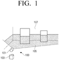
- FIG. 1 is a perspective view illustrating a distance measuring device according to the prior art.
- FIG. 2 is a view illustrating an image captured by a camera of FIG. 1
- FIG. 3 is a side view illustrating the distance measuring device of FIG. 1 .
- the distance measuring device 100 emits structured light 105 in the form of a line onto an obstacle 107 by using a light source 101 such as a laser, and obtains an image 110 of reflected light as illustrated in FIG. 2 by using a sensor such as a camera 103.
- a sensor such as a camera 103.
- Reference numeral 112 in FIG. 2 denotes an obstacle.
- the distance between the emission point of the structured light and the obstacle 107 may be calculated by triangulation.
- the resolution decreases as the distance to the obstacle 107 increases as illustrated in FIG. 3 .
- the distance change at the same angular intervals increases, so that a distance error at a long distance increases.
- FIG. 3 as an example, there are four pixels (not illustrated) in the image sensor of the camera 103, and the structured light irradiated from the laser light source 101 enters the camera 103 from five positions separated by the same angular interval with respect to the camera 103.
- This problem of low resolution at a long distance may be solved by using a sensor having a high resolution.
- a sensor having a high resolution is expensive and a processor capable of processing it also requires high performance.
- Another way to increase the far-field resolution is to increase the distance between the light source and the camera.
- increasing the distance between the light source and the camera increases the size of the distance measuring device.
- the size of a device such as a mobile robot in which the distance measuring device is mounted may not be reduced.
- Another way to increase the far-field resolution is to use an optical system with a narrow angle of view.
- the horizontal angle of view is also reduced, and thus, there is a problem in that it is not suitable for a distance measuring device that requires a wide horizontal field of view.
- the disclosure is invented in view of the above problems, and relates to a wide-angle high-resolution distance measuring device having a wide angle of view in a horizontal direction and at the same time having a high far-field resolution.
- a wide-angle high-resolution distance measuring device may include a light source configured to irradiate structured light; a camera configured to form an image by capturing reflected light, which is the structured light irradiated from the light source and reflected from an obstacle; and a resolution correction lens disposed in front of the camera and configured to correct the reflected light reflected from the obstacle and incident on the camera, wherein resolution of the image formed by the camera becomes uniform regardless of distance.
- the resolution correction lens may be formed to sequentially change resolution so that a central portion has a high resolution and an outer peripheral portion has a low resolution.
- the camera may include an image sensor, the light source may be disposed so that reflected light reflected from a distant obstacle is incident toward a first end of the image sensor, and reflected light reflected from a nearby obstacle is incident toward a second end of the image sensor, and the resolution correction lens may be disposed such that the central portion is adjacent to the first end of the image sensor and the outer peripheral portion is adjacent to the second end of the image sensor.
- the resolution correction lens may have a circular cross-section
- the image sensor may be formed in a rectangular flat plate, and the image sensor may be disposed such that the first end of the image sensor is spaced a predetermined distance downward from a straight line passing through a center of the resolution correction lens, and both corners of the second end of the image sensor are in contact with an inner surface of the circular cross-section of the resolution correction lens.
- the resolution correction lens may have a circular cross-section, wherein the image sensor may be formed in a rectangular flat plate, and the image sensor may be disposed such that the first end of the image sensor is spaced a predetermined distance downward from a straight line passing through a center of the resolution correction lens, and the second end of the image sensor is in contact with an outer circumferential surface of the circular cross-section of the resolution correction lens.
- the resolution correction lens may include a wide-angle lens.
- the resolution correction lens may be formed to have a highest resolution at one end portion along an outer circumferential surface and a lowest resolution at another end portion facing the one end portion.
- the camera may include an image sensor, the light source may be disposed so that reflected light reflected from a distant obstacle is incident toward a first end of the image sensor through the one end portion of the resolution correction lens, and reflected light reflected from a nearby obstacle is incident toward a second end of the image sensor through the another end portion of the resolution correction lens, and the resolution correction lens may be disposed such that its center coincides with a center of the image sensor.
- the resolution correction lens may include a first axis and a second axis perpendicular to the first axis, and the resolution correction lens may be formed such that distortion in the second axis direction is greater than distortion in the first axis direction.
- the resolution correction lens may be a half-cylinder lens, and the half-cylinder lens may be disposed such that the first axis is parallel to the structured light irradiated from the light source.
- the resolution correction lens may be a double-concave cylinder lens, and the double-concave cylinder lens may be disposed such that the second axis is parallel to the structured light irradiated from the light source.
- the wide-angle high-resolution distance measuring device may include a processor configured to control the light source and the camera, wherein the processor may control so that the light source turns on at predetermined time intervals to irradiate structured light and the camera captures an image.
- the processor may shift a timing of turning on the light source by a predetermined time.
- a resolution correction lens is used to maintain a horizontal angle of view and improve the far-field resolution.
- first component may be referred to as a second component
- second component may also be referred to as a first component
- FIG. 4 is a side view illustrating a wide-angle high-resolution distance measuring device according to an embodiment of the disclosure.
- FIG. 5 is a cross-sectional view schematically illustrating a structure of a camera used in FIG. 4 .
- FIG. 6 is a view illustrating a relationship between a lens and an image sensor of a camera, and
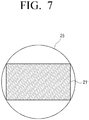
- FIG. 7 is a view illustrating a relationship between a lens and an image sensor of a camera.
- a wide-angle high-resolution distance measuring device 1 may include a light source 10, a camera 20, and a resolution correction lens 30.
- the light source 10 may be formed to irradiate structured light having a predetermined shape.
- a line laser is used as the light source 10.
- the line laser 10 may be formed to irradiate the structured light in a straight line to the obstacle 107.
- the line laser 10 may be formed to output flat light in a fan shape.
- the camera 20 may be disposed under the light source 10.
- the light source 10 and the camera 20 may be arranged so that the center line of the light source 10 and the center line of the camera 20 are positioned on the same virtual vertical plane.
- the camera 20 may be configured to capture reflected light, which is the structured light that is irradiated from the light source 10, is reflected from an obstacle, and then enters the camera 20, to form an image.
- the camera 20 may include an image sensor 21 and a focus lens 23 to focus light on the image sensor 21.
- the image sensor 21 may be configured to form an image by capturing reflected light reflected from an obstacle.
- the image sensor 21 may be formed as a flat plate having a substantially rectangular shape, and may be formed in a form in which a plurality of pixels are integrated.
- the image sensor 21 may use the same image sensor used in the distance measuring device according to the prior art. For example, an image sensor of 5 to 10 million pixels may be used.
- the aspect ratio of the image sensor 21 may be 4:3 or 16:9.
- the focus lens 23 may be formed so that the reflected light reflected from the obstacle is incident to focus on the image sensor 21.
- the focus lens 23 is formed of one lens, but the focus lens 23 is not limited thereto.
- the focus lens 23 may be formed as a lens assembly including two or more lenses as long as it can focus the reflected light on the image sensor.
- the angle of view may be determined according to the size of the image sensor 21.
- the vertical angle of view is 67.5 degrees.
- the vertical angle of view is 50.6 degrees.
- the vertical angle of view also increases at the same time.
- the far-field resolution of the distance measuring device may deteriorate. In order to improve the far-field resolution, it is necessary to reduce the vertical angle of view.
- the wide-angle high-resolution distance measuring device 1 may use the resolution correction lens 30 to widen the horizontal angle of view and narrow the vertical angle of view.
- the resolution correction lens 30 may be disposed in front of the camera 20, and may be configured to correct the reflected light, which is reflected from the obstacle and incident on the camera 20, so that the resolution of the image formed on the image sensor 21 of the camera 20 is uniform.
- the resolution correction lens 30 may be manufactured separately from the camera 20 and disposed in front of the camera 20.
- the resolution correction lens 30 may be integrally formed with the focus lens 23 in front of the focus lens 23 of the camera 20.
- the resolution correction lens 30 may be formed as a lens assembly including two or more lenses instead of a single lens.
- the uniform resolution means that the intervals between the plurality of points P1, P2, P3, P4, P5, and P6 positioned on the light beam L irradiated from the light source 10 are the same as illustrated in FIG. 4 .
- each of the intervals G between the pluralities of points corresponds to one pixel of the image sensor 21.
- the intervals G between the plurality of points are all the same, light having the same interval is input to one pixel regardless of the distance, so that the image sensor 21 may accurately recognize the obstacle regardless of the distance. Accordingly, the far-field resolution of the distance measuring device 1 may be improved.
- FIG. 4 illustrates the case that the image sensor 21 of the camera 20 has five pixels (not illustrated) and the structured light irradiated from the light source 10 is inputted to the pixels of the image sensor 21 from six positions P1, P2, P3, P4, P5, and P6.
- light passing between P1 and P2 is input to one pixel
- light passing between P2 and P3 is input to one pixel
- light passing between P3 and P4 is input to one pixel
- light passing between P4 and P5 is input to one pixel
- light passing between P5 and P6 is input to one pixel.
- the intervals G between six points are the same.
- the interval G between the points P1 and P2, the interval G between the points P2 and P3, the interval G between the points P3 and P4, the interval G between the points P4 and P5, and the interval G between the points P5 and P6 are all the same.
- angles between the lines L1, L2, L3, L4, L5, and L6 which connect the pixels of the image sensor 21 and the points P1, P2, P3, P4, P5, and P6 are different.
- the angle between the two lines L1 and L2 passing through one pixel and the points P1 and P2 the angle between the two lines L2 and L3 passing through one pixel and the points P2 and P3, the angle between the two lines L3 and L4 passing through one pixel and the points P3 and P4, the angle between the two lines L4 and L5 passing through one pixel and the points P4 and P5, and the angle between the two lines L5 and L6 passing through one pixel and the points P5 and P6 are all different.
- the angle between the two lines L1 and L2 passing through one pixel and the points P1 and P2 is the largest, the angle between two lines gradually decreases, and the angle between the two lines L5 and L6 passing through one pixel and the points P5 and P6 is the smallest.
- a wide-angle lens having a central portion 31 with a high resolution and an outer peripheral portion 32 with a low resolution is used as the resolution correction lens 30.
- the resolution correction lens 30 may be designed so that the central portion 31 thereof has a high resolution, the outer peripheral portion 32 thereof has a low resolution, and the resolution between the central portion 31 and the outer peripheral portion 32 changes sequentially by using lens distortion.
- the light source 10 and the image sensor 21 are disposed so that the reflected light reflected from a long distance passes through the central portion 31 of the resolution correction lens 30 and enters the image sensor 21.
- the light source 10 is disposed so that the reflected light reflected from a distant obstacle is incident toward the first end 21a (see FIG. 8 ) of the image sensor 21 and the reflected light reflected from a nearby obstacle is incident toward the second end 21b (see FIG. 8 ) of the image sensor 21 facing the first end 21a.
- the resolution correction lens 30 is disposed such that the central portion 31 is adjacent to the first end 21a of the image sensor 21 and the outer peripheral portion 32 is adjacent to the second end 21b of the image sensor 21.
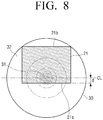
- FIG. 8 is a view illustrating an arrangement relationship between an image sensor and a resolution correction lens in the wide-angle high-resolution distance measuring device of FIG. 4 .
- the resolution correction lens 30 may have a circular cross-section, and may be formed so that the resolution decreases from the central portion 31 toward the outer peripheral portion 32.
- the central portion 31 of the resolution correction lens 30 is high-resolution
- the outer peripheral portion 32 is low-resolution.
- a general wide-angle lens may be used as an example of the resolution correction lens 30.
- the image sensor 21 may be formed in a rectangular flat plate. In this embodiment, the image sensor 21 has the aspect ratio of 4:3.
- the image sensor 21 is disposed such that the first end 21a of the image sensor 21 is located below a predetermined distance d from the center line CL in parallel with the center line CL passing through the center of the resolution correction lens 30 and both corners of the second end 21b of the image sensor 21 contact the inner surface of the circular cross-section of the resolution correction lens 30.
- the distance d between the image sensor 21 and the center line CL of the resolution correction lens 30 may be determined by a high-resolution region of the resolution correction lens 30 that can increase the far-field resolution.
- the first end 21a of the image sensor 21 may be disposed to coincide with the center line CL of the resolution correction lens 30.
- the reflected light reflected from a short distance is incident on the upper end portion of the image sensor 21, that is, toward the second end 21b, and the reflected light reflected from a far distance is incident on the lower end portion of the image sensor 21, that is, toward the first end 21a.
- the reflected light reflected from the short distance enters the image sensor 21 through the outer peripheral portion 32 of the resolution correction lens 30 having a low-resolution
- the reflected light reflected from the far distance enters the image sensor 21 through the central portion 31 of the resolution correction lens 30 having a high-resolution.
- FIG. 9 is a view illustrating another example of an arrangement relationship between an image sensor and a resolution correction lens in the wide-angle high-resolution distance measuring device of FIG. 4 .
- the resolution correction lens 30 may have a circular cross-section, and may be formed so that the resolution decreases from the central portion 31 toward the outer peripheral portion 32.
- the central portion 31 of the resolution correction lens 30 is high-resolution
- the outer peripheral portion 32 is low-resolution.
- a general wide-angle lens may be used as an example of the resolution correction lens 30.
- the image sensor 21 may be formed in a rectangular flat plate. In this embodiment, the image sensor 21 has the aspect ratio of 4:3.
- the image sensor 21 is disposed such that the first end 21a of the image sensor 21 is located below a predetermined distance d from the center line CL in parallel with the center line CL passing through the center of the resolution correction lens 30 and the second end 21b of the image sensor 21 is in contact with the outer circumferential surface of the circular cross-section of the resolution correction lens 30.
- the distance d between the image sensor 21 and the center line CL of the resolution correction lens 30 may be determined by a high-resolution region of the resolution correction lens 30 capable of increasing the far-field resolution.
- the first end 21a of the image sensor 21 may be disposed to coincide with the center line CL of the resolution correction lens 30.
- the reflected light reflected from a short distance is incident on the upper end portion of the image sensor 21, that is, toward the second end 21b, and the reflected light reflected from a far distance is incident on the lower end portion of the image sensor 21, that is, toward the first end 21a. Therefore, the reflected light reflected from the short distance enters the image sensor 21 through the outer peripheral portion 32 of the resolution correction lens 30 having a low-resolution, and the reflected light reflected from the far distance enters the image sensor 21 through the central portion 31 of the resolution correction lens 30 having a high-resolution.
- the interval of light input to each pixel of the image sensor 21 may be formed approximately identically as illustrated in FIG. 4 . Therefore, the far-field resolution of the distance measuring device may be improved.
- the wide-angle high-resolution distance measuring device 1 may detect an obstacle with an error of about 1% at a long distance (for example, 6 M) indoors, and may detect an obstacle with an error of about 1% at a long distance (for example, 15 M) outdoors.
- the resolution correction lens 30 is formed in a circular shape as illustrated in FIGS. 8 and 9 , there is an advantage in that it is easy to manufacture the resolution correction lens 30.
- the center of the image sensor 21 and the center of the resolution correction lens 30 are arranged to be eccentric.
- the image sensor 21 and the resolution correction lens 30 may be disposed so that the center of the image sensor 21 and the center of the resolution correction lens 30 are aligned with each other as illustrated in FIG. 10 .
- FIG. 10 is a view illustrating another example of an arrangement relationship between an image sensor and a resolution correction lens in the wide-angle high-resolution distance measuring device of FIG. 4 .
- the resolution correction lens 30' may have a circular cross-section and may be formed to have the highest resolution at one end of the outer circumferential surface of the resolution correction lens 30' and the lowest resolution at the other end of the outer circumferential surface opposite to the one end thereof.
- the resolution correction lens 30' may be formed so that the resolution gradually decreases from the upper end 30a to the lower end 30b.
- the upper portion adjacent to the upper end 30a of the resolution correction lens 30' is high-resolution
- the lower portion adjacent to the lower end 30b thereof is low-resolution.
- the resolution of the middle portion between the upper end 30a and the lower end 30b is formed to change sequentially in parallel with the upper end of the image sensor 21.
- a plurality of parallel dotted lines 30c indicate a region in which the resolution is changed.
- the image sensor 21 may be formed in a rectangular flat plate. In this embodiment, the image sensor 21 has the aspect ratio of 4:3. The image sensor 21 is disposed so that the center of the image sensor 21 is aligned with the center of the resolution correction lens 30'.
- the reflected light reflected from a short distance is incident on the lower end portion of the image sensor 21, that is, toward the first end 21a, and the reflected light reflected from a far distance is incident on the upper end portion of the image sensor 21, that is, toward the second end 21b. Therefore, the reflected light reflected from the short distance enters the image sensor 21 through the lower end portion of the resolution correction lens 30' having a low-resolution, and the reflected light reflected from the far distance enters the image sensor 21 through the upper end portion of the resolution correction lens 30' having a high-resolution.
- the resolution correction lens may be formed to have a rectangular cross-section corresponding to the image sensor 21 rather than a circular shape.
- FIG. 11 is a side view illustrating a wide-angle high-resolution distance measuring device according to another embodiment of the disclosure.
- FIG. 12 is a plan view illustrating the wide-angle high-resolution distance measuring device of FIG. 11
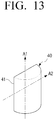
- FIG. 13 is a perspective view illustrating a half-cylinder lens used in the wide-angle high-resolution distance measuring device of FIG. 11 .
- a wide-angle high-resolution distance measuring device 2 may include a light source 10, a camera 20, and a resolution correction lens 40.
- the light source 10 may be formed to irradiate structured light having a predetermined shape.
- a line laser is used as the light source 10.
- the line laser 10 may irradiate the structured light in a straight line to the obstacle 107.
- the line laser 10 may be formed to output flat light in a fan shape.
- the camera 20 may be disposed under the light source 10.
- the light source 10 and the camera 20 may be arranged so that the center line CL1 of the light source 10 and the center line CL2 of the camera 20 are positioned on the same virtual vertical plane.
- the camera 20 may be configured to capture reflected light, which is the structured light that is irradiated from the light source 10, is reflected from an obstacle, and then enters the camera 20, to form an image.
- the camera 20 may include an image sensor 21 and a focus lens 23 to focus light on the image sensor 21 (see FIG. 5 ).
- the camera 20 may use a lens having a wide angle in the horizontal direction. For example, a camera 20 having a horizontal angle of view of 90 degrees and a vertical angle of view of about 60 degrees may be used.
- a lens in which distortion in one direction is greater than distortion in the other direction may be used as the resolution correction lens 40.
- the resolution correction lens 40 may have a first axis A1 and a second axis A2 perpendicular to the first axis A1, and may be formed so that the distortion in the direction of the second axis A2 is greater than the distortion in the direction of the first axis A1.
- the resolution correction lens 40 may be disposed so that the direction of the second axis A2 having a large distortion coincides with the direction in which the angle of view is to be changed.
- the resolution correction lens 40 may be disposed in front of the camera 20 so that the direction of the first axis A1 having a small distortion is parallel to the light plane LP formed by the structured light irradiated from the light source 10.
- a half-cylinder lens may be used as the resolution correction lens 40 to reduce the angle of view in the vertical direction.
- the half-cylinder lens 40 may be used to reduce a vertical angle of view of about 60 degrees to about 20 degrees.
- FIG. 13 illustrates an example of the half-cylinder lens 40.
- the half-cylinder lens 40 may include a first axis A1 and a second axis A2 perpendicular to each other on a rectangular plane 41.
- the first axis A1 is an axis in the vertical direction of the half-cylinder lens 40
- the second axis A2 is an axis of the width direction of the half-cylinder lens 40 and perpendicular to the first axis A1 on the rectangular plane 41. Because the shape is uniform in the direction of the first axis A1, there is almost no distortion. However, distortion exists in the direction of the second axis A2, that is, in the width direction of the half-cylinder lens 40. Accordingly, the distortion in the direction of the second axis A2 is greater than the distortion in the direction of the first axis A1.
- the half-cylinder lens 40 may be disposed in front of the camera 20 so that the second axis A2 of the half-cylinder lens 40 is parallel to the virtual vertical plane in which the light source 10 and the camera 20 are disposed.
- the angle of view in the vertical direction of the camera 20 may be reduced, so that the light intervals of the reflected light incident on the camera 20 are made uniform regardless of the distance, thereby increasing the resolution.
- the far-field resolution may be increased.
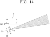
- FIG. 14 is a side view illustrating a wide-angle high-resolution distance measuring device according to another embodiment of the disclosure.
- FIG. 15 is a plan view illustrating the wide-angle high-resolution distance measuring device of FIG. 14
- FIG. 16 is a perspective view illustrating a double-concave cylinder lens used in the wide-angle high-resolution distance measuring device of FIG. 14 .
- a wide-angle high-resolution distance measuring device 3 may include a light source 10, a camera 20, and a resolution correction lens 50.
- the light source 10 may be formed to irradiate structured light having a predetermined shape.
- a line laser is used as the light source 10.
- the line laser 10 may irradiate the structured light in a straight line to the obstacle 107.
- the line laser 10 may be formed to output flat light in a fan shape.
- the camera 20 may be disposed under the light source 10.
- the light source 10 and the camera 20 may be arranged so that the center line CL1 of the light source 10 and the center line CL2 of the camera 20 are positioned on the same virtual vertical plane.
- the camera 20 may be configured to capture reflected light, which is the structured light that is irradiated from the light source 10, is reflected from an obstacle, and then enters the camera 20, to form an image.
- the camera 20 may include an image sensor 21 and a focus lens 23 to focus light on the image sensor 21 (see FIG. 5 ).
- the camera 20 may use a lens having a narrow angle in the horizontal direction.
- a camera 20 having a horizontal angle of view of 30 degrees and a vertical angle of view of 20 degrees may be used. In this case, the angle of view in the horizontal direction of the camera 20 may be widened in order to widen the field of view of the distance measuring device 3.
- the resolution correction lens 50 a lens in which distortion in one direction is greater than distortion in the other direction may be used in order to increase the angle of view in the horizontal direction, for example, to increase the angle of view in the horizontal direction from 30 degrees to 90 degrees.
- the resolution correction lens 50 may have a first axis A1 and a second axis A2 perpendicular to the first axis A1, and may be formed so that the distortion in the direction of the second axis A2 is greater than the distortion in the direction of the first axis A1.
- the resolution correction lens 50 may be disposed so that the direction of the second axis A2 having a large distortion coincides with the direction in which the angle of view is to be changed.
- the resolution correction lens 50 may be disposed in front of the camera 20 so that the direction of the second axis A2 having a large distortion is parallel to the structured light irradiated from the light source 10.
- a double-concave cylinder lens may be used as the resolution correction lens 50 to increase the angle of view in the horizontal direction.
- the double-concave cylinder lens 50 capable of increasing the horizontal angle of view of the camera 20 from 30 degrees to 90 degrees may be used.
- FIG. 16 illustrates an example of the double-concave cylinder lens 50.
- the double-concave cylinder lens 50 may be formed in a shape in which concave grooves are formed in a longitudinal direction in a rectangular flat plate.
- the double-concave cylinder lens 50 has a concave shape on each of both side surfaces, so that the middle portion of the flat plate is thinner than the edge thereof. Because the double-concave cylinder lens 50 functions as a general concave lens, the double-concave cylinder lens 50 may spread incident light.
- the double-concave cylinder lens 50 may include a first axis A1 and a second axis A2 perpendicular to each other on an imaginary central plane 51.
- the first axis A1 is an axis extending in the vertical direction of the double-concave cylinder lens 50 on the central plane 51
- the second axis A2 is an axis perpendicular to the first axis A1 and extending in the left-right direction of the double-concave cylinder lens 50 on the central plane 51. Because the shape is uniform in the direction of the first axis A1, there is almost no distortion. However, distortion exists in the direction of the second axis A2, that is, in the width direction of the double-concave cylinder lens 50. Accordingly, the distortion in the direction of the second axis A2 is greater than the distortion in the direction of the first axis A1.
- the double-concave cylinder lens 50 may be disposed in front of the camera 20 so that the second axis A2 of the double-concave cylinder lens 50 is parallel to the light plane LP formed by the structured light irradiated from the light source 10.
- the double-concave cylinder lens 50 is disposed in front of the camera 20 as described above, the horizontal angle of view of the camera 20 may be increased, so that the horizontal angle of view of the camera 20 may be made a wide angle.
- the wide-angle high-resolution distance measuring device 3 as illustrated in FIGS. 14 and 15 , because the angle of view in the vertical direction of the camera 20 may be maintained at a narrow angle and the angle of view in the horizontal direction may be increased to a wide angle, the field of view may be increased while maintaining high resolution at a long distance.
- the resolution correction lenses 40 and 50 are used as an optical system disposed in front of the camera 20 to adjust the angle of view.
- the lens may not be used as the optical system for adjusting the angle of view.
- a wide-angle high-resolution distance measuring device may be configured using a concave mirror or a convex mirror capable of functioning the same as the lens.
- a plurality of mobile robots having the wide-angle high-resolution distance measuring devices 1, 2, and 3 according to an embodiment of the disclosure may be used.
- light interference may occur due to structured lights irradiated from light sources of the plurality of wide-angle high-resolution distance measuring devices.
- FIG. 17 is a functional block diagram illustrating a wide-angle high-resolution distance measuring device according to an embodiment of the disclosure.
- FIG. 18 is a diagram illustrating time charts of light sources when light interference occurs between two wide-angle high-resolution distance measuring devices according to an embodiment of the disclosure disposed in two mobile robots.
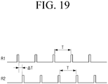
- FIG. 19 is a diagram illustrating time charts of light sources when light interference between two wide-angle high-resolution distance measuring devices according to an embodiment of the disclosure disposed in two mobile robots is avoided.
- a wide-angle high-resolution distance measuring device 1 may include a light source 10, a camera 20, and a processor 60.
- the light source 10 may be configured to irradiate structured light
- the camera 20 may be configured to form an image by capturing reflected light that is reflected from an obstacle and incident on the camera 20.
- the light source 10 and the camera 20 are the same as or similar to the light source 10 and the camera 20 according to the above-described embodiment; therefore, detailed descriptions thereof are omitted.
- the processor 60 may be configured to control the light source 10 and the camera 20, and identify a distance to an obstacle using a position when the light source 10 emits light.
- the processor 60 turns on the light source 10 at predetermined intervals to irradiate the structured light, and controls the camera 20 to form an image by capturing the reflected light, which is the structured light reflected by an obstacle and incident on the camera 20.
- the processor 60 may synchronously control the light source 10 and the camera 20 to form an image only when the light source 10 is turned on.
- the processor 60 may calculate the distance to the obstacle using the distance between the light source 10 and the camera 20 and the acquired image.
- the processor 60 may control the light source 10 to emit structured light at a predetermined time interval.
- the light sources 10 of two distance measuring devices 1 emit light, so that light interference may occur between the two distance measuring devices 1.
- the processor 60 of the distance measuring device 1 of a first mobile robot R1 identifies that light interference is occurred by the distance measuring device 1 of a second mobile robot R2. Then, the processor 60 of the distance measuring device 1 of the first mobile robot R1 may shift the timing of turning on the light source 10 by a predetermined time to avoid the light interference.
- the light source 10 of the distance measuring device 1 of the first mobile robot R1 may emit structured light at a predetermined time interval in the form of pulses, and the light source 10 of the distance measuring device 1 of the second mobile robot R2 may emit structured light in the form of pulses.
- the processor 60 of the distance measuring device 1 of the first mobile robot R1 detects a structured light signal through the camera 20 in the state that the processor 60 does not turn on the light source 10 at the timing to turn on the light source 10 (part C in FIG. 18 ), it may be seen that light interference is occurred due to the structured light irradiated from the light source 10 of the second mobile robot R2.
- the processor 60 of the distance measuring device 1 of the first mobile robot R1 may shift the timing of turning on the light source 10 by a predetermined time ⁇ T as illustrated in FIG. 19 .
- the shift time ⁇ T may be smaller than the time interval T at which the light source 10 is turned on.
- the timing at which the distance measuring device 1 of the first mobile robot R1 emits light may not coincide with the timing at which the distance measuring device 1 of the second mobile robot R2 emits light. Accordingly, light interference between the distance measuring devices of the two mobile robots R1 and R2 may be avoided.
- a resolution correction lens may be used to improve the far-field resolution while maintaining the horizontal angle of view.
- a horizontal angle of view when a horizontal angle of view is narrow by using a narrow angle lens to obtain a narrow vertical angle of view, a horizontal angle of view may be increased to a wide angle while maintaining the vertical angle of view by using a resolution correction lens.
- the wide-angle high-resolution distance measuring device may increase a far-field resolution by changing an optical system without using a high-resolution image sensor, thereby reducing manufacturing cost.
- the wide-angle high-resolution distance measuring device may increase the far-field resolution by changing the optical system without increasing the distance between the light source and the camera, which causes an increase in the size of the distance measuring device. Therefore, miniaturization of a mobile robot or the like equipped with the distance measuring device may be achieved.
Landscapes
- Engineering & Computer Science (AREA)
- Physics & Mathematics (AREA)
- Multimedia (AREA)
- Signal Processing (AREA)
- Electromagnetism (AREA)
- General Physics & Mathematics (AREA)
- Radar, Positioning & Navigation (AREA)
- Remote Sensing (AREA)
- Computer Networks & Wireless Communication (AREA)
- Optics & Photonics (AREA)
- Computing Systems (AREA)
- Theoretical Computer Science (AREA)
- Computer Vision & Pattern Recognition (AREA)
- Optical Radar Systems And Details Thereof (AREA)
- Measurement Of Optical Distance (AREA)
Applications Claiming Priority (2)
| Application Number | Priority Date | Filing Date | Title |
|---|---|---|---|
| KR1020190037294A KR102693894B1 (ko) | 2019-03-29 | 2019-03-29 | 광각 고해상도 거리 측정 장치 |
| PCT/KR2020/004099 WO2020204458A1 (ko) | 2019-03-29 | 2020-03-26 | 광각 고해상도 거리 측정 장치 |
Publications (2)
| Publication Number | Publication Date |
|---|---|
| EP3873085A1 true EP3873085A1 (de) | 2021-09-01 |
| EP3873085A4 EP3873085A4 (de) | 2021-12-08 |
Family
ID=72666844
Family Applications (1)
| Application Number | Title | Priority Date | Filing Date |
|---|---|---|---|
| EP20783192.6A Pending EP3873085A4 (de) | 2019-03-29 | 2020-03-26 | Hochauflösende weitwinkel-entfernungsmesseinrichtung |
Country Status (5)
| Country | Link |
|---|---|
| US (1) | US11982805B2 (de) |
| EP (1) | EP3873085A4 (de) |
| KR (1) | KR102693894B1 (de) |
| CN (1) | CN113475056B (de) |
| WO (1) | WO2020204458A1 (de) |
Families Citing this family (4)
| Publication number | Priority date | Publication date | Assignee | Title |
|---|---|---|---|---|
| US12198361B2 (en) * | 2020-05-18 | 2025-01-14 | Nec Corporation | Anti-spoofing 3D face reconstruction using infrared structure light |
| TWI773133B (zh) * | 2020-07-10 | 2022-08-01 | 大陸商廣州印芯半導體技術有限公司 | 測距裝置以及測距方法 |
| US11921205B2 (en) * | 2020-11-24 | 2024-03-05 | Pixart Imaging Inc. | Method for eliminating misjudgment of reflective lights and optical sensing system |
| US11826906B2 (en) * | 2020-11-24 | 2023-11-28 | Pixart Imaging Inc. | Method for eliminating misjudgment of reflective light and optical sensing system |
Family Cites Families (25)
| Publication number | Priority date | Publication date | Assignee | Title |
|---|---|---|---|---|
| JPH07240840A (ja) * | 1994-02-25 | 1995-09-12 | Opt Japan Kk | 光学的情報読取装置 |
| JPH07280939A (ja) | 1994-04-13 | 1995-10-27 | Nippondenso Co Ltd | 反射測定装置 |
| US7176960B1 (en) * | 1999-09-20 | 2007-02-13 | The Trustees Of Columbia University In The City Of New York | System and methods for generating spherical mosaic images |
| JP2002006127A (ja) * | 2000-06-19 | 2002-01-09 | Seiko Epson Corp | 光学ローパスフィルタおよびそれを用いた画像入力装置 |
| JP2006018184A (ja) * | 2004-07-05 | 2006-01-19 | Komatsu Lite Seisakusho:Kk | 撮像レンズ及びそれを用いた撮像モジュール |
| KR100791389B1 (ko) | 2006-12-26 | 2008-01-07 | 삼성전자주식회사 | 스트럭쳐드 라이트를 이용한 거리 측정 장치 및 방법 |
| DE102008014912B4 (de) * | 2008-03-19 | 2023-01-19 | Vorwerk & Co. Interholding Gmbh | Selbsttätig verfahrbares Bodenstaub-Aufsammelgerät |
| JP5148353B2 (ja) | 2008-04-25 | 2013-02-20 | 三菱重工業株式会社 | 水中航走体および障害物探知装置 |
| JP2012231911A (ja) * | 2011-04-28 | 2012-11-29 | Olympus Corp | 光走査装置および走査型観察装置 |
| KR101382476B1 (ko) * | 2012-02-20 | 2014-04-08 | (주)마이크로인피니티 | 거리 측정 장치 |
| KR102047224B1 (ko) | 2012-11-13 | 2019-11-22 | 엘지디스플레이 주식회사 | 마스크리스 노광장비 및 이의 왜곡차 측정 및 매칭방법 |
| WO2014100250A2 (en) | 2012-12-18 | 2014-06-26 | Nissi Vilcovsky | Devices, systems and methods of capturing and displaying appearances |
| KR102046944B1 (ko) | 2014-01-13 | 2019-11-20 | 페이스북, 인크. | 서브-레졸루션 광학 검출 |
| KR102158212B1 (ko) * | 2014-02-05 | 2020-09-22 | 엘지전자 주식회사 | 입체적 형상을 감지하기 위한 카메라 및 그것의 제어 방법 |
| US20170247745A1 (en) * | 2014-09-12 | 2017-08-31 | Click Diagnostics, Inc. | Multiplex optical detection |
| JP2017533000A (ja) * | 2014-09-16 | 2017-11-09 | ケアストリーム ヘルス インク | レーザ投影を用いる歯科用表面撮像装置 |
| DE102015119668B3 (de) * | 2015-11-13 | 2017-03-09 | Sick Ag | Optoelektronischer Sensor und Verfahren zur Erfassung eines Objekts |
| RU2642149C2 (ru) | 2016-01-12 | 2018-01-24 | Самсунг Электроникс Ко., Лтд. | Составная линза и содержащая ее система отображения |
| US10302906B2 (en) * | 2016-04-20 | 2019-05-28 | Shenzhen Ned Optics Co., Ltd. | Eyepiece optical system for near-eye display, and head-mounted display device |
| CN105974427B (zh) * | 2016-06-24 | 2021-05-04 | 上海图漾信息科技有限公司 | 结构光测距装置及方法 |
| KR101883180B1 (ko) | 2016-08-01 | 2018-07-30 | 엘지전자 주식회사 | 차량용 라이다 장치 |
| JP6844307B2 (ja) | 2017-02-24 | 2021-03-17 | 株式会社Ihi | 画角調整方法 |
| JP2018179911A (ja) | 2017-04-20 | 2018-11-15 | 株式会社デンソー | 測距装置及び距離情報取得方法 |
| WO2019099297A1 (en) * | 2017-11-16 | 2019-05-23 | Princeton Optronics, Inc. | Structured light illuminators including a chief ray corrector optical element |
| US10607315B2 (en) * | 2018-01-09 | 2020-03-31 | Immervision, Inc. | Constant resolution continuous hybrid zoom system |
-
2019
- 2019-03-29 KR KR1020190037294A patent/KR102693894B1/ko active Active
-
2020
- 2020-03-26 CN CN202080014362.XA patent/CN113475056B/zh active Active
- 2020-03-26 EP EP20783192.6A patent/EP3873085A4/de active Pending
- 2020-03-26 US US17/599,888 patent/US11982805B2/en active Active
- 2020-03-26 WO PCT/KR2020/004099 patent/WO2020204458A1/ko not_active Ceased
Also Published As
| Publication number | Publication date |
|---|---|
| KR20200114860A (ko) | 2020-10-07 |
| CN113475056B (zh) | 2024-04-09 |
| EP3873085A4 (de) | 2021-12-08 |
| KR102693894B1 (ko) | 2024-08-12 |
| WO2020204458A1 (ko) | 2020-10-08 |
| US11982805B2 (en) | 2024-05-14 |
| US20220163794A1 (en) | 2022-05-26 |
| CN113475056A (zh) | 2021-10-01 |
Similar Documents
| Publication | Publication Date | Title |
|---|---|---|
| US11982805B2 (en) | Wide-angle, high-resolution distance measurement device | |
| CN107607960B (zh) | 一种光学测距的方法及装置 | |
| KR101911006B1 (ko) | 이미지 센서 포지셔닝 장치 및 방법 | |
| US11619742B2 (en) | Line beam scanning optical system and laser radar | |
| WO2016056545A1 (ja) | 走査光学系及び投受光装置 | |
| US20030107819A1 (en) | 3d shape-measuring apparatus using biaxial anamorphic magnification | |
| CN106546216A (zh) | 距离测量方法、装置、摄像头和移动终端 | |
| JP2014020889A (ja) | 物体検出装置 | |
| JP7031724B2 (ja) | Lidar装置 | |
| WO2019163210A1 (ja) | 走査型光学系、およびライダー | |
| EP2787731A2 (de) | Bildprojektionsgerät und den Eingang Objekterkennungsverfahren | |
| CN113391321B (zh) | 测距装置和测距方法 | |
| US8860929B2 (en) | High precise laser rangefinder | |
| JP7157386B2 (ja) | レーザーレーダー用の走査型の光学系及びレーザーレーダー装置 | |
| US20140246573A1 (en) | Electronic device | |
| CN112255818A (zh) | 成像校正单元与成像模块 | |
| US20090141000A1 (en) | System and method for performing optical navigation using horizontally oriented imaging lens | |
| JP7468661B2 (ja) | 物体までの距離を計算するためのlidar装置及び方法 | |
| US20190096865A1 (en) | Optical navigation module capable of performing lateral detection and adjusting tracking distance | |
| CN221465737U (zh) | 激光雷达 | |
| CN111562559B (zh) | 激光雷达装置及其接收模块 | |
| US11762066B2 (en) | Multi-beam scanning system | |
| CN101010626A (zh) | 成像装置 | |
| JP2011090166A (ja) | ステレオ撮像装置 | |
| US11714295B2 (en) | Imaging correction unit and imaging module |
Legal Events
| Date | Code | Title | Description |
|---|---|---|---|
| STAA | Information on the status of an ep patent application or granted ep patent |
Free format text: STATUS: THE INTERNATIONAL PUBLICATION HAS BEEN MADE |
|
| PUAI | Public reference made under article 153(3) epc to a published international application that has entered the european phase |
Free format text: ORIGINAL CODE: 0009012 |
|
| STAA | Information on the status of an ep patent application or granted ep patent |
Free format text: STATUS: REQUEST FOR EXAMINATION WAS MADE |
|
| 17P | Request for examination filed |
Effective date: 20210524 |
|
| AK | Designated contracting states |
Kind code of ref document: A1 Designated state(s): AL AT BE BG CH CY CZ DE DK EE ES FI FR GB GR HR HU IE IS IT LI LT LU LV MC MK MT NL NO PL PT RO RS SE SI SK SM TR |
|
| REG | Reference to a national code |
Ref country code: DE Ref legal event code: R079 Free format text: PREVIOUS MAIN CLASS: H04N0005232000 Ipc: G01S0007481000 |
|
| A4 | Supplementary search report drawn up and despatched |
Effective date: 20211109 |
|
| RIC1 | Information provided on ipc code assigned before grant |
Ipc: G06T 7/521 20170101ALI20211103BHEP Ipc: H04N 5/222 20060101ALI20211103BHEP Ipc: G01S 17/48 20060101ALI20211103BHEP Ipc: G01S 17/08 20060101ALI20211103BHEP Ipc: G01S 17/93 20200101ALI20211103BHEP Ipc: G01S 17/86 20200101ALI20211103BHEP Ipc: H04N 5/225 20060101ALI20211103BHEP Ipc: H04N 5/232 20060101ALI20211103BHEP Ipc: G01S 7/481 20060101AFI20211103BHEP |
|
| DAV | Request for validation of the european patent (deleted) | ||
| DAX | Request for extension of the european patent (deleted) | ||
| STAA | Information on the status of an ep patent application or granted ep patent |
Free format text: STATUS: EXAMINATION IS IN PROGRESS |
|
| 17Q | First examination report despatched |
Effective date: 20230719 |