EP3872403A1 - Verfahren zur bestimmung einer reinigungszyklus-dauer - Google Patents
Verfahren zur bestimmung einer reinigungszyklus-dauer Download PDFInfo
- Publication number
- EP3872403A1 EP3872403A1 EP21157389.4A EP21157389A EP3872403A1 EP 3872403 A1 EP3872403 A1 EP 3872403A1 EP 21157389 A EP21157389 A EP 21157389A EP 3872403 A1 EP3872403 A1 EP 3872403A1
- Authority
- EP
- European Patent Office
- Prior art keywords
- camera
- cooking
- cleaning cycle
- soiling
- evaluation electronics
- Prior art date
- Legal status (The legal status is an assumption and is not a legal conclusion. Google has not performed a legal analysis and makes no representation as to the accuracy of the status listed.)
- Granted
Links
Images
Classifications
-
- F—MECHANICAL ENGINEERING; LIGHTING; HEATING; WEAPONS; BLASTING
- F24—HEATING; RANGES; VENTILATING
- F24C—DOMESTIC STOVES OR RANGES ; DETAILS OF DOMESTIC STOVES OR RANGES, OF GENERAL APPLICATION
- F24C14/00—Stoves or ranges having self-cleaning provisions, e.g. continuous catalytic cleaning or electrostatic cleaning
-
- F—MECHANICAL ENGINEERING; LIGHTING; HEATING; WEAPONS; BLASTING
- F24—HEATING; RANGES; VENTILATING
- F24C—DOMESTIC STOVES OR RANGES ; DETAILS OF DOMESTIC STOVES OR RANGES, OF GENERAL APPLICATION
- F24C7/00—Stoves or ranges heated by electric energy
- F24C7/08—Arrangement or mounting of control or safety devices
- F24C7/082—Arrangement or mounting of control or safety devices on ranges, e.g. control panels, illumination
- F24C7/085—Arrangement or mounting of control or safety devices on ranges, e.g. control panels, illumination on baking ovens
Definitions
- the present invention relates to a method for determining the duration of a cleaning cycle of a method for thermal cleaning of a cooking chamber in a cooking appliance, in which sensor signals from an optical sensor are fed to evaluation electronics, which use the sensor signals to determine the degree of soiling of the cooking chamber by evaluating the sensor signals .
- Shading effects caused by trays or grids in the cooking space are not recognized and are not taken into account.
- the respective measurement is limited to the window size to the optical sensor and is imprecise. It is not possible to tell the nature of the pollution.
- the reference value must also have been saved beforehand, although it remains unclear what should actually serve as the reference value.
- the methods named from the prior art are unsuitable for determining the duration of a cleaning cycle with the required accuracy. Since the duration of the cleaning cycle has an influence on the cleaning result, the duration of the cleaning cycle should be adapted to the time required for sufficient cleaning. If the duration of the cleaning cycle is too short, the cooking space is not yet sufficiently clean; if the duration is too long, energy and resources are wasted unnecessarily. However, it would be desirable to be able to determine the duration of a cleaning cycle as precisely as possible in order to use only as many energy resources as possible for a cleaning cycle as are necessary to achieve the desired cleaning result. In addition, a cleaning cycle can be better planned if it is known in advance when the cooking appliance will be available for normal operation again.
- the object is achieved for a generic method in that a camera is used as an optical sensor which generates several camera images as sensor signals during the course of a cleaning cycle, the camera images are transmitted from the camera to the evaluation electronics, and the evaluation electronics use the transmitted camera images with image processing software evaluates by determining a degree of soiling of the cooking chamber for a camera image and from the last determined value for one Degree of pollution derives a current value for the remaining duration of the cleaning cycle.
- Soiling in a cooking space is usually caused by greasy splashes or drops in the form of liquid that spontaneously escape from the food being cooked.
- the stains are then mostly roughly distributed on a surface of a carrier material in the cooking space and are semi-transparent and yellow-dark in color. They are not only to be found on the surfaces of the side, rear, bottom and top panels of the cooking appliance that point into the cooking space, as well as on the inside of the door to the cooking space, but mostly also on the cover plate or lens of the camera as spots and cloudiness that appear in the respective camera image are also visible.
- the spots described usually show a blurred contour of a spot in the camera image, which becomes lighter from the inside out. This effect is created by the formation of drops on the surface of the carrier material to which the respective drop adheres in the cooking space.
- the spots can be recognized as more or less blurred shadows.
- All of the above-described soiling can be recognized and assessed as part of an evaluation of one or more camera images using image processing software. It makes no fundamental difference whether the dirt is only on the cover plate of the camera and / or on the surfaces of the side, rear walls, floor and ceiling panels of the cooking appliance and the inside of the door to the cooking space.
- the different focal planes of the camera allow the different spots to be recognized, differentiated and evaluated accordingly, because they appear in a camera image with different contrasts.
- the current value for the remaining duration of the cleaning cycle can consist of a time value in seconds or minutes, but also a simple switch-on or switch-off signal with which the cleaning device, for example the heating for pyrolytic cleaning, is switched on or off.
- a prognosis about the expected remaining duration of a cleaning cycle can already be created on the basis of a single and first camera image, which can also be created and evaluated before the start of a cleaning cycle.
- This temporal prognosis created on the basis of the evaluation of only one camera image, can be used, for example, to make a decision as to whether a pyrolysis program should be started now or at a later point in time.
- a prognosis of an approximate time value can suffice to assess whether the downtime of the cooking appliance for conventional cooking processes over the predicted duration of the pyrolysis program is too long or can be tolerated and thus triggered by an operator.
- a single camera image can be sufficient to show how urgent it is to clean the cooking chamber by means of a cleaning cycle. With the individual camera image, it is already possible to evaluate the degree of soiling of the cooking space and to derive a recommendation from this to initiate appropriate cleaning. If cleaning is not yet required, a corresponding recommendation is not made and unnecessary pyrolysis cycles are avoided.
- the first camera image being created promptly at the beginning of the cleaning cycle in order to obtain a first prognosis for the duration of the cleaning cycle that has started, and a second camera image based on it at a later point in time which is then evaluated as to whether and for how long the cleaning cycle should be continued.
- More than two camera images can also be created and evaluated during a cleaning cycle, for example timed and / or event-related, such as reaching certain temperature values in the cooking space, in order to decide whether the cooking space should be heated to a higher temperature level or not.
- the accuracy in evaluating the degree of soiling of the cooking chamber naturally increases if several camera images are included in the evaluation. At least at the beginning and at the end of a use of the cooking space, camera images can be created which are evaluated by the evaluation electronics to assess the degree of soiling of the cooking space. Even more precise evaluations and temporal forecasts can be made if additional camera images are created and included in the evaluation during an ongoing cleaning cycle. In particular, continuous monitoring of a cleaning cycle by several camera images and their comparison by means of the evaluation electronics can be used to recognize the cleaning progress that has already been made and to use it to control the course of the cleaning cycle and to determine its duration.
- the stain appears darker at the start of pyrolysis than a comparatively thinner splash.
- the stains described change in size and color in such a way that they first get darker and smaller and then mostly disappear.
- the same also applies to the large-scale soiling described.
- These changes can be taken into account in an updated assessment of the degree of soiling of the cooking space and the remaining duration of a pyrolysis process. This is particularly true when the time interval between camera images compared with one another is included in the evaluation. If certain discolorations and changes in the size and shape of the spots have occurred within a certain time interval, conclusions can be drawn about how long it will take until the spots have completely disappeared. This is even more true for a consideration in which the corresponding changes from several time intervals are compared with one another and processed into a temporal forecast for the remaining duration.
- a camera directed into the cooking space and connected to electronics is nowadays often built into at least higher quality cooking appliances in order to be able to cover smart home functionalities.
- Using the existing camera for the additional function means that there are hardly any additional costs for the user.
- the suitable integration of the evaluation electronics into the already existing device electronics of the cooking appliance is sufficient.
- the duration of the cleaning cycle it is possible to adapt the duration of the cleaning cycle to the time required for adequate cleaning.
- a cleaning cycle lasts exactly as long as is necessary to achieve a satisfactory cleaning result without wasting energy or other resources.
- the determination of a temperature prevailing in the cooking space can be included.
- the cooking appliance is available again as soon as possible after a cleaning cycle.
- the planning of when a cleaning cycle is to be carried out is also simplified by the forecast according to the method. With the evaluation of the camera images by the evaluation electronics, unnecessary cleaning cycles can also be avoided entirely.
- the degree of soiling of the cooking space is determined by counting the number, size and position of the spots and evaluating the brightness of the camera image with a fixed exposure time.
- a current value for the duration of the cleaning cycle can then be derived from reference tables that the evaluation electronics access when evaluating the transmitted camera images with the image processing software.
- the degree of soiling of the cooking space is determined by comparing the current camera image with stored camera images.
- the stored camera images can be stored in the evaluation electronics, but they can also be called up remotely via an Internet connection, or the current camera image is evaluated by evaluation electronics that are arranged remotely as an expert system on an Internet server, so that current between the cooking device and the evaluation electronics Camera images and the data determined from them are exchanged for the duration of the cleaning cycle.
- the evaluation electronics check the lighting of the cooking chamber and / or switch it on when the camera creates a camera image.
- the image quality of the camera image to be created is increased.
- the quality of the prognosis regarding the necessity and duration of a cleaning cycle is increased as a result.
- the evaluation electronics evaluate a camera image in order to recognize whether the cooking space has been cleared for a cleaning cycle. If the evaluation electronics detect that there is material in the cooking chamber at the beginning of a cleaning cycle that should have been removed from it because it cannot withstand the temperatures that occur during pyrolytic cleaning and could possibly even catch fire, the evaluation electronics can send a warning signal to the device electronics output that blocks the start of a cleaning cycle.
- the "empty" status of the cooking chamber can be determined by the evaluation electronics, for example, by the evaluation electronics comparing a current camera image with a camera image that would have to result in an actually empty cooking chamber.
- the evaluation electronics generate a switch-off signal to switch off a cleaning cycle and / or a signal to lower the temperature in the cooking chamber to the device electronics when it has detected a sufficiently clean cooking chamber in the context of the image evaluation.
- the switch-off signal to the appliance electronics of the cooking appliance ensures that the cleaning cycle is not accidentally continued beyond what is recognized as necessary.
- the signal for lowering the temperature in the cooking chamber can also serve to avoid excessively high temperatures in the cooking chamber, which are not or no longer necessary to achieve a sufficient cleaning result, and to avoid wasting energy as a result.
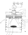
- FIGURE shows an exemplary embodiment of a cooking appliance according to the invention with a camera.
- a cooking device 30 is shown as an example.
- the cooking appliance 30 is designed here as a baking oven and has a housing 2 in which a cooking space 6 delimited by a housing wall 4 is arranged.
- the baking oven also has a 2D camera 8 designed as a fixed focus camera as an optical sensor, an opening 4.1 for the camera 8 being formed in the housing wall 4, which is covered by a lens 10 designed as a collecting lens made of borosilicate glass.
- a cooking space lighting 11 designed as a baking muffle light is built onto a cooking space ceiling 4.2 of the housing 4.
- the baking muffle lamp 11 is designed here at the same time as camera lighting 11. Accordingly, the fixed focus camera 8 in the present exemplary embodiment can be constructed more simply.
- the cooking space lighting 11 can also be arranged on a side wall or consist of a combination of ceiling and side lighting.
- the camera 8 is designed to take internal recordings of the cooking space 6 and is arranged accordingly on the housing 2. Since the cooking space 6 is relatively wide and flat, an objective 8.1 of the camera 8 has a correspondingly large object-side opening angle.
- the camera can also be designed as a plenoptic camera, TOF camera or stereo camera, that is to say using 3D technology. Cameras designed as thermal imaging cameras are also conceivable. In addition to single images, it is also possible to record sequences of images and moving images.
- the opening 4.1 is closed essentially gas-tight by the converging lens 10 and a seal 12 arranged between the converging lens 10 and the cooking space ceiling 4.2 of the housing wall 4 and designed as a glass fiber seal.
- a metal gasket with or without a graphite coating can be used. Accordingly, the one with a In the cooking process taking place in the cooking process of a food 16 placed on a food support 14 to be cooked, vapors generated do not escape in an undesired manner through the opening 4.1.
- the camera 8 can also be arranged in a lateral position or in any other position relative to the cooking chamber 6, so that it can also use these positions to take photos of the cooking chamber 6 and the dirt present therein which can be used for evaluation purposes.
- the collecting lens 10 made of borosilicate glass and the glass silk seal 12 protect the camera 8 from substances contained in the vapor and from the high temperatures occurring during the cooking process. This is particularly important since the cooking appliance 30 is equipped as a self-cleaning cooking appliance 30, that is to say with a pyrolysis function. Far higher temperatures result in pyrolysis operation.
- the cooking space 6 is thermally insulated from the environment in a manner known to those skilled in the art by an essentially circumferential insulation layer 18.
- the insulation layer 18 is only partially shown in the figure.
- the opening 4.1 in the cooking space wall 4 is arranged here in the center of the cooking space ceiling 4.2 of the housing wall 4.
- the opening 4.1 is kept as small as possible in order to have to break through the insulation layer 18 as little as possible at this point.
- the opening 4.1 is shown clearly enlarged in the figure for the sake of clarity.
- the camera 8 Due to the insulation layer 18, but also for the purpose of lower temperature stress on the camera 8 due to the thermal radiation, the camera 8 is arranged further away from the cooking chamber ceiling 4.2 and thus from the cooking chamber 6 in a cooler area of the housing 2.
- the opening 4.1 can therefore be made so small because a converging lens 10 is used here.
- the converging lens 10 widens the beam path of the light, symbolized in the figure by dashed lines 19, through the opening 4.1.
- this enables the cooking chamber 6 to be completely reproduced in the essential areas on the images recorded with the camera 8, despite a reduced object-side opening angle of the objective 8.1 of the camera 8.
- the image angle in the plane of the sheet shown in the figure can thus be increased from approximately 50 ° to approximately 110 °.
- the aforementioned angle information cannot be found in the schematic representation.
- the opening 4.1 is made relatively small, the opening 4.1 can be arranged in the region of a top heat heater 20 in the cooking space ceiling 4.2 without the opening 4.1 and the top heat radiator 20 affect each other negatively.
- the upper heating element 20 does not appear on the images recorded with the camera 8.
- the cooking space lighting 11 is also arranged on the cooking space ceiling 4.2 of the cooking space wall 4 in such a way that there is no undesired interaction between the cooking space lighting 11 and the upper heating element 20.
- the camera 8 and the converging lens 10 are additionally arranged in a cooling channel 2.1 of the housing 2.
- the camera 8 and the converging lens 10 are in a heat transfer connection with the cooling air guided in the cooling channel 2.1.
- the cooling channel 2.1 is designed here as an air duct 2.1 of the cooking appliance.
- the air duct 2.1 is connected to the housing wall 4 in a flow-conducting manner by means of a flange 22 that is likewise resistant to chemicals and temperature, and the air duct 2.1 is connected to the environment in a substantially gas-tight manner.
- the air duct 2.1 of the cooking appliance 30 is used to suck off the vapors that arise during cooking processes in the cooking space 6 from the cooking space 6 and discharge it into the open environment.
- the vapor-air mixture is guided in the air duct 2.1 formed in the housing 2.
- the cooking appliance is also cooled in this way.
- the arrangement of the camera 8 and the converging lens 10 in the air duct 2.1 makes it possible to dispense with an additional active cooling device. Accordingly, the cooking appliance 30 according to the invention according to the present exemplary embodiment can be implemented with fewer components and thus more cost-effectively.
- the individual components of the cooking appliance 30 according to the invention are partially shown at a distance from one another in the figure; see, for example, the distance between the insulation layer 18 and the cooking space ceiling 4.2 of the housing wall 4. This is only for a better overview.
- the components of the cooking appliance 30 according to the invention are connected to one another in a manner known to a person skilled in the art, unless explicitly stated otherwise on the basis of the exemplary embodiment.
- the camera 8 can also be designed as a plenoptic camera, TOF camera or stereo camera, that is to say using 3D technology. Cameras designed as thermal imaging cameras are also conceivable. In addition to single images, it is also possible to record sequences of images and moving images.
- a camera image 32 recorded by the camera 8 is transmitted to the evaluation electronics 40 in each case.
- the cooking appliance 30 is connected to the evaluation electronics 40, to which the camera images 32 made by the camera 8 are sent for the purpose of determining the Duration 46 of a cleaning cycle can be transmitted.
- the image processing software 42 is programmed in such a way that it can determine the degree of soiling 44 of the cooking chamber 6 based on the optical representation of the interior of the cooking appliance 30 resulting from the camera image 32.
- the evaluation electronics 40 determine the remaining duration 46 for which the cleaning cycle is still to be continued.
- the determined value for the duration 46 of the cleaning cycle can be transmitted to the evaluation electronics 40 and / or the temperature control of the cooking appliance 30.
- the invention is not limited to the present embodiment.
- teaching according to the invention can also be used advantageously in other cooking appliances.
Landscapes
- Engineering & Computer Science (AREA)
- Chemical & Material Sciences (AREA)
- Combustion & Propulsion (AREA)
- Mechanical Engineering (AREA)
- General Engineering & Computer Science (AREA)
- Chemical Kinetics & Catalysis (AREA)
- Electric Stoves And Ranges (AREA)
- Investigating Or Analyzing Materials Using Thermal Means (AREA)
Abstract
Description
- Die vorliegende Erfindung bezieht sich auf ein Verfahren zur Bestimmung der Dauer eines Reinigungszyklusses eines Verfahrens zur thermischen Reinigung eines Garraums in einem Gargerät, bei dem Sensorsignale eines optischen Sensors einer Auswerteelektronik zugeführt werden, die anhand der Sensorsignale den Verschmutzungsgrad des Garraums über die Auswertung der Sensorsignale bestimmt.
- Aus der gattungsgemäßen Schrift
DE 101 28 024 A1 ist es bekannt, den Beginn und/oder die Dauer eines Reinigungszyklusses zur thermischen Reinigung eines Garraums, beispielsweise mittels Pyrolyse als Beispiel für einen Reinigungszyklus mit einem thermischen Reinigungsverfahren, anhand der Auswertung der von einem optischen Sensor erfassten, von einer Lichtquelle in den Garraum abgestrahlten optischen Strahlung zu steuern. Über den optischen Sensor wird gemessen, wie stark die Lichtintensität im Garraum im Vergleich zu einem Referenzwert abgenommen hat. Der optische Sensor wird in der der Lichtquelle gegenüberliegenden Garraumwand angeordnet. Dieses Verfahren ist nachteilig, weil die vom optischen Sensor erfasste Lichtintensität nur in dem kleinen Bereich der Anordnung des optischen Sensors gemessen und das Messergebnis zumindest auch von Fremdlicht verfälscht wird, das durch die Gerätetür in den Garraum einfällt. Abschattungseffekte durch im Garraum befindliche Bleche oder Roste werden nicht erkannt und bleiben unberücksichtigt. Die jeweilige Messung ist auf die Fenstergröße zum optischen Sensor beschränkt und ungenau. Es ist nicht möglich, die Art und Weise der Verschmutzung zu erkennen. Der Referenzwert muss zudem vorher gespeichert worden sein, wobei unklar bleibt, was überhaupt als Referenzwert dienen soll. - Aus der Schrift
DE 10 2016 206 483 A1 ist es bekannt, bei einem gewerblichen Gargerät durch den Vergleich eines aktuellen Bildes einer Garfläche mit einem Referenzbild einer verschmutzten, eine Reinigung benötigenden Garfläche oder eines Garproduktes zu bestimmen, wann eine Reinigung notwendig ist. Bei diesem Verfahren geht es nur darum, den richtigen Zeitpunkt, nicht aber die Dauer des Reinigungszyklusses zu bestimmen. Die Reinigung selbst soll auf Basis eines vor Beginn des Reinigungszyklusses ausgewählten Reinigungsprogramms erfolgen, das aber während seines Ablaufs nicht mehr verändert wird. Die Bilder werden mit elektronischen Bildsensoren wie beispielsweise CCD- oder CMOS-Sensoren aufgenommen. Die aufgenommenen Bilder können digital weiterverarbeitet werden. - Aus der Schrift
DE 10 2011 002 187 A1 ist es bekannt, dem Garraum eines Gargeräts eine Kamera zuzuordnen, die von ihr aufgenommene Bilder aus dem Garraum an eine Anzeigeeinrichtung weiterleitet. Die auf die Anzeigeeinrichtung übertragenen Bilder ermöglichen eine Sichtkontrolle des Gargutes, ohne dafür die Garraumtür öffnen zu müssen. Eine Verwertung der übertragenen Bilder für Reinigungszwecke ist in dieser Schrift nicht offenbart. Die Anordnung einer Kamera in einem Gargerät ist beispielsweise in der SchriftDE 10 2016 124 312 A1 offenbart. - Aus den Schriften
DE 10 2010 039 280 A1 undDE 107 06 186 A1 ist es bekannt, die Heizleistung bei einem Pyrolysevorgang in einem Hausgerät, bei dem die dabei auftretenden Rauchgase von einem Katalysator umgesetzt werden, in Abhängigkeit von der Temperatur des Katalysators zu regeln. Die Heizleistung wird dabei reduziert, wenn sich die Differenz zwischen den Temperaturen des Katalysators und des Heizraums verändert, wobei die Differenz mit einem Schwellwert verglichen wird. Die Temperaturmessung im Katalysator ist als Regelgröße für die Regelung eines Pyrolysevorgangs ungeeignet, weil sie keine optische Beurteilung der Sauberkeit des Gargeräts und des Reinigungsergebnisses zulässt. Bei einer nur geringen Rauchentwicklung haben die Temperaturwerte nur eine geringe Aussagekraft. - Die aus dem Stand der Technik benannten Verfahren sind ungeeignet, die Dauer eines Reinigungszyklusses mit der erforderlichen Genauigkeit zu bestimmen. Da die Dauer des Reinigungszyklusses einen Einfluss auf das Reinigungsergebnis hat, sollte die Dauer des Reinigungszyklusses an den für eine ausreichende Reinigung erforderlichen Zeitaufwand angepasst sein. Bei einer zu kurzen Dauer des Reinigungszyklusses ist der Garraum noch nicht ausreichend sauber, bei einer zu langen Dauer werden unnötig Energie und Ressourcen verschwendet. Es wäre aber wünschenswert, die Dauer eines Reinigungszyklusses möglichst genau bestimmen zu können, um für einen Reinigungszyklus möglichst nur so viele Energie-Ressourcen aufzuwenden, wie sie erforderlich sind, um das gewünschte Reinigungsergebnis zu erzielen. Zudem kann ein Reinigungszyklus besser geplant werden, wenn vorher bekannt ist, ab wann das Gargerät wieder für den Normalbetrieb verfügbar ist.
- Demgemäß ist es die Aufgabe der vorliegenden Erfindung, ein Verfahren zu schaffen, das die vorstehend beschriebenen Nachteile aus dem Stand der Technik überwindet.
- Die Aufgabe wird für ein gattungsgemäßes Verfahren gelöst, indem als optischer Sensor eine Kamera verwendet wird, die während des Verlaufs eines Reinigungszyklusses mehrere Kamerabilder als Sensorsignale generiert, die Kamerabilder von der Kamera an die Auswerteelektronik übertragen werden, und die Auswerteelektronik die übertragenen Kamerabilder mit einer Bildverarbeitungssoftware auswertet, indem sie für ein Kamerabild jeweils einen Verschmutzungsgrad des Garraums bestimmt und aus dem zuletzt ermittelten Wert für einen Verschmutzungsgrad einen aktuellen Wert für die verbleibende Dauer des Reinigungszyklusses ableitet.
- Verschmutzungen in einem Garraum erfolgen meist durch fetthaltige Spritzer oder Tropfen in Form von Flüssigkeit, die aus einem Gargut spontan austreten. Dabei sind die Flecken dann meist auf einer Oberfläche eines Trägermaterials im Garraum grob verteilt und halb transparent von gelbdunkler Farbe. Sie finden sich nicht nur auf den in den Garraum weisenden Oberflächen der Seiten-, Rückwände, Boden- und Deckenbleche des Gargeräts sowie der Innenseite der Tür zum Garraum, sondern meistens auch auf der Abdeckscheibe oder der Linse der Kamera als Flecken und Eintrübungen, die im jeweiligen Kamerabild auch sichtbar sind. Die beschriebenen Flecken zeigen im Kamerabild meist eine unscharfe Kontur eines Flecks, wobei dieser von innen nach außen heller wird. Dieser Effekt entsteht durch Tropfenbildung auf der Oberfläche des Trägermaterials, dem der jeweilige Tropfen im Garraum anhaftet. Im Rahmen einer softwaregestützten Bildverarbeitung können die Flecken als mehr oder weniger unscharfe Schatten erkannt werden.
- Es ist auch möglich, dass insbesondere auf dem Garraumboden, aber auch an den Seitenwänden oder der Rückwand größere Flecken durch auslaufende Flüssigkeiten entstehen. Diese sind meist in das Material der Oberfläche des Trägermaterials, wie beispielsweise einer Emaillebeschichtung eines Blechs, eingebrannt und von dunkler Farbe. Auch solche größeren Flecken sind in einem jeweiligen Kamerabild sichtbar.
- Es kann auch vorkommen, dass sich fetthaltiger Wrasen an den Oberflächen im Garraum großflächig niederschlägt. Dies erfolgt meist durch das Verkochen von fetthaltigen Flüssigkeiten. Größere Schichtdicken fetthaltiger Wrasen führen zu einer reduzierten Helligkeit und einer verringerte Schärfe des Kamerabildes.
- Alle vorstehend beschriebenen Verschmutzungen können im Rahmen einer Auswertung eines oder mehrerer Kamerabilder mit einer Bildverarbeitungssoftware erkannt und bewertet werden. Dabei macht es keinen grundsätzlichen Unterschied, ob sich die Verschmutzungen nur auf der Abdeckscheibe der Kamera und/oder auf den Oberflächen der Seiten-, Rückwände, Boden- und Deckenbleche des Gargeräts sowie der Innenseite der Tür zum Garraum befinden. Durch unterschiedliche Fokusebenen der Kamera können die unterschiedlichen Flecken gut erkannt, unterschieden und entsprechend bewertet werden, weil sie in einem Kamerabild mit unterschiedlichen Kontrasten erscheinen.
- Der aktuelle Wert für die verbleibende Dauer des Reinigungszyklusses kann aus einem Zeitwert in Sekunden oder Minuten, aber auch aus einem einfachen Ein- oder Ausschaltsignal bestehen, mit dem die Reinigungseinrichtung, beispielsweise die Heizung für eine pyrolytische Reinigung, ein- oder ausgeschaltet wird.
- Eine Prognose über die voraussichtliche Rest-Dauer eines Reinigungszyklusses kann schon auf der Basis eines einzigen und ersten Kamerabildes erstellt werden, das auch schon vor dem Beginn eines Reinigungszyklusses erstellt und ausgewertet werden kann. Diese auf der Auswertung nur eines Kamerabilds erstellte zeitliche Prognose kann beispielsweise dazu dienen, eine Entscheidung zu fällen, ob ein Pyrolyseprogramm jetzt oder zu einem späteren Zeitpunkt gestartet werden soll. Eine Prognose eines ungefähren Zeitwerts kann reichen, um zu beurteilen, ob die Ausfallzeit des Gargeräts für herkömmliche Garvorgänge über die prognostizierte Dauer des Pyrolyseprogramms hinweg zu lang ist oder toleriert und somit von einem Bediener ausgelöst werden kann. Genauso kann ein einziges Kamerabild auch schon ausreichen, um anzuzeigen, wie dringend überhaupt eine Reinigung des Garraums mittels eines Reinigungszyklusses ist. Mit dem einzelnen Kamerabild ist schon möglich, eine Bewertung des Verschmutzungsgrades des Garraums vorzunehmen und daraus eine Empfehlung abzuleiten, eine entsprechende Reinigung auszulösen. Ist eine Reinigung noch nicht erforderlich, unterbleibt eine entsprechende Empfehlung, und unnötige Pyrolysezyklen werden dadurch vermieden.
- Es ist aber sinnvoll, im Verlauf eines Reinigungszyklusses zumindest zwei Kamerabilder zu erstellen, wobei das erste Kamerabild zeitnah zum Beginn des Reinigungszyklusses erstellt wird, um eine erste Prognose für die Dauer des begonnenen Reinigungszyklusses zu erhalten, und zu einem späteren Zeitpunkt ein zweites Kamerabild, anhand dessen dann bewertet wird, ob und wie lange der Reinigungszyklus noch fortgesetzt werden soll. Es können auch mehr als zwei Kamerabilder während eines Reinigungszyklusses erstellt und ausgewertet werden, beispielsweise zeitgetaktet und/oder anlassbezogen, wie beispielsweise der Erreichung bestimmter Temperaturwerte im Garraum, um zu entscheiden, ob der Garraum noch auf eine höhere Temperaturstufe aufgeheizt werden soll oder nicht.
- Die Genauigkeit in der Bewertung des Verschmutzungsgrades des Garraums nimmt naturgemäß zu, wenn mehrere Kamerabilder in die Bewertung einfließen. So können zumindest zu Beginn und zum Abschluss einer Benutzung des Garraums jeweils Kamerabilder erstellt werden, die für die Bewertung des Verschmutzungsgrades des Garraums von der Auswerteelektronik ausgewertet werden. Noch genauere Bewertungen und zeitliche Prognosen lassen sich erstellen, wenn während eines laufenden Reinigungszyklusses zusätzliche Kamerabilder erstellt und in die Bewertung einbezogen werden. Insbesondere eine fortlaufende Überwachung eines Reinigungszyklusses durch mehrere Kamerabilder und ihren Vergleich mittels der Auswerteelektronik kann dazu genutzt werden, den bereits erzielten Reinigungsfortschritt zu erkennen und für die Steuerung des Verlaufs des Reinigungszyklusses und der Bestimmung von dessen Dauer zu nutzen.
- Ist die Schichtdicke eines Spritzers dicker, so erscheint der Fleck zum Start der Pyrolyse dunkler als ein vergleichsweise dünnerer Spritzer. Während eines Pyrolysevorgangs verändern sich die beschriebenen Flecken in ihrer Größe und Farbe dahingehend, dass sie erst dunkler und kleiner werden und dann größtenteils verschwinden. Gleiches gilt auch für die beschriebenen großflächigen Verschmutzungen. Diese Veränderungen können bei einer aktualisierten Bewertung des Verschmutzungsgrades des Garraums und der verbleibenden Dauer eines Pyrolysevorgangs berücksichtigt werden. Das gilt insbesondere dann, wenn das Zeitintervall zwischen miteinander verglichenen Kamerabildern in die Bewertung mit einfließt. Haben sich in einem bestimmten Zeitintervall bestimmte Verfärbungen und Veränderungen in der Größe und Form der Flecken ergeben, lassen sich daraus Rückschlüsse darauf ableiten, wie lange es dauern wird, bis die Flecken vollständig verschwunden sind. Das gilt erst recht für eine Betrachtung, in der die entsprechenden Veränderungen aus mehreren Zeitintervallen miteinander verglichen und in eine zeitliche Prognose für die Restdauer verarbeitet werden.
- Eine in den Garraum gerichtete und mit einer Elektronik verbundene Kamera wird heute zumindest in hochwertigere Gargeräte bereits häufig eingebaut, um damit Smart Home-Funktionalitäten abdecken zu können. Durch die Nutzung der bereits vorhandenen Kamera für die zusätzliche Funktion entstehen also kaum zusätzliche Kosten für den Benutzer. Es genügt die geeignete Einbindung der Auswerteelektronik in die bereits vorhandene Geräteelektronik des Gargeräts.
- Die Erfahrung hat gezeigt, dass geringere Verschmutzungen bereits bei geringeren Pyrolysetemperaturen in einem ersten Drittel eines Reinigungszyklusses verascht werden können. Ein Reinigungszyklus wird dann mit niedrigeren Pyrolysetemperaturen ausgeführt, als es bei einer unbewerteten Überprüfung des Reinigungsergebnisses während der Pyrolyse möglich wäre. Dadurch wird eine erhebliche Energieeinsparung erzielt. Sind in früheren Kamerabildern erkannte Flecken in einem aktuellen Kamerabild gänzlich verschwunden oder nur noch sehr klein und nur als gleichfarbige, hellgraue kontraststärkere Restasche zu erkennen, so kann der Reinigungszyklus unmittelbar abgeschlossen werden. So ist es möglich, Reinigungszyklen zu verkürzen, wenn der gewünschte Reinheitsgrad des Garraums schon vor Ablauf der prognostizierten Zykluszeit während eines Reinigungszyklusses erreicht wird. Auch dadurch werden erhebliche Energieeinsparungen erzielt.
- Mit dem erfindungsgemäßen Verfahren ist es möglich, die Dauer des Reinigungszyklusses an den für eine ausreichende Reinigung erforderlichen Zeitaufwand anzupassen. Ein Reinigungszyklus dauert genau so lange, wie für die Erzielung eines zufriedenstellenden Reinigungsergebnisses erforderlich ist, ohne dass dafür Energie oder sonstige Ressourcen verschwendet werden. In die Bestimmung der verbleibenden Dauer des Reinigungszyklusses kann die Bestimmung einer dabei herrschenden Temperatur im Garraum einfließen. Das Gargerät ist nach einem Reinigungszyklus schnellstmöglich wieder verfügbar. Auch die Planung, wann ein Reinigungszyklus durchgeführt werden soll, wird durch die verfahrensgemäße Prognose vereinfacht. Mit der Auswertung der Kamerabilder durch die Auswerteelektronik können zudem unnötige Reinigungszyklen gänzlich vermieden werden.
- Nach einer Ausgestaltung der Erfindung wird der Verschmutzungsgrad des Garraums durch eine Auszählung der Anzahl, Größe und Position der Flecken sowie eine Bewertung der Helligkeit des Kamerabildes bei einer festen Belichtungszeit bestimmt. Aus Referenztabellen, auf die die Auswerteelektronik bei der Auswertung der übertragenen Kamerabilder mit der Bildverarbeitungssoftware zugreift, kann dann ein aktueller Wert für die Dauer des Reinigungszyklusses abgeleitet werden.
- Nach einer Ausgestaltung der Erfindung wird der Verschmutzungsgrad des Garraums durch einen Vergleich des aktuellen Kamerabildes mit gespeicherten Kamerabildern bestimmt. Die gespeicherten Kamerabilder können in der Auswerteelektronik gespeichert sein, sie können aber auch remote über eine Internetverbindung aufrufbar sein, oder das aktuelle Kamerabild wird von einer Auswerteelektronik ausgewertet, die remote als Expertensystem auf einem Internetserver angeordnet ist, so dass zwischen dem Gargerät und der Auswerteelektronik aktuelle Kamerabilder und daraus ermittelte Daten für die Dauer des Reinigungszyklusses ausgetauscht werden.
- Nach einer Ausgestaltung der Erfindung prüft die Auswerteelektronik die Beleuchtung des Garraums und/oder schaltet diese ein, wenn die Kamera ein Kamerabild erstellt. Durch die Beleuchtung des Garraums während der Erstellung eines Kamerabildes wird die Bildqualität des zu erstellenden Kamerabildes erhöht. Die Prognosequalität über die Notwendigkeit und Dauer eines Reinigungszyklusses wird dadurch gesteigert.
- Nach einer Ausgestaltung der Erfindung wertet die Auswerteelektronik ein Kamerabild aus, um zu erkennen, ob der Garraum für einen Reinigungszyklus leergeräumt ist. Erkennt die Auswerteelektronik, dass sich zum Beginn eines Reinigungszyklusses Material im Garraum befindet, das daraus entnommen sein sollte, weil es den im Verlauf einer pyrolytischen Reinigung auftretenden Temperaturen nicht standhalten und möglicherweise sogar in Brand geraten könnte, so kann die Auswerteelektronik an die Geräteelektronik ein Warnsignal ausgeben, durch das der Start eines Reinigungszyklusses blockiert wird. Der "leer"-Status des Garraums kann von der Auswerteelektronik beispielsweise festgestellt werden, indem die Auswerteelektronik ein aktuelles Kamerabild mit einem Kamerabild vergleicht, das sich bei einem tatsächlich leeren Garraum ergeben müsste.
- Nach einer Ausgestaltung der Erfindung generiert die Auswertelektronik ein Abschaltsignal zur Abschaltung eines Reinigungszyklusses und/oder ein Signal zur Temperaturabsenkung im Garraum an die Geräteelektronik, wenn sie im Rahmen der Bildauswertung einen ausreichend sauberen Garraum detektiert hat. Durch das Abschaltsignal an die Geräteelektronik des Gargeräts wird sichergestellt, dass der Reinigungszyklus nicht versehentlich über das als notwendig erkannte Maß hinaus fortgeführt wird. Genauso kann das Signal zur Temperaturabsenkung im Garraum dazu dienen, zu hohe Temperaturen im Garraum, die nicht oder nicht mehr zur Erzielung eines ausreichenden Reinigungsergebnisses erforderlich sind, und eine dadurch eintretende Energieverschwendung zu vermeiden.
- Ein Ausführungsbeispiel der Erfindung ist in der Zeichnung rein schematisch dargestellt und wird nachfolgend näher beschrieben. Es zeigt die einzige Figur ein Ausführungsbeispiel eines erfindungsgemäßen Gargeräts mit einer Kamera.
- In der einzigen Figur ist ein erfindungsgemäßes Gargerät 30 exemplarisch dargestellt. Das Gargerät 30 ist hier als ein Backofen ausgebildet und weist ein Gehäuse 2 auf, in dem ein durch eine Gehäusewand 4 begrenzter Garraum 6 angeordnet ist. Ferner weist der Backofen eine als Fixfokuskamera ausgebildete 2D-Kamera 8 als optischen Sensor auf, wobei in der Gehäusewand 4 eine durch eine als Sammellinse aus Borosilikatglas ausgebildete Linse 10 verdeckte Öffnung 4.1 für die Kamera 8 ausgeformt ist.
- In dem Garraum 6 ist eine als Backmuffelleuchte ausgebildete Garraumbeleuchtung 11 an einer Garraumdecke 4.2 des Gehäuses 4 angebaut. Die Backmuffelleuchte 11 ist hier gleichzeitig als Kamerabeleuchtung 11 ausgebildet. Entsprechend kann die Fixfokuskamera 8 in dem vorliegenden Ausführungsbeispiel einfacher aufgebaut sein. Alternativ kann die Garraumbeleuchtung 11 auch an einer Seitenwand angeordnet sein oder aus einer Kombination aus Decken- und Seitenbeleuchtung bestehen.
- Die Kamera 8 ist zur Erstellung von Innenaufnahmen des Garraums 6 ausgebildet und entsprechend an dem Gehäuse 2 angeordnet. Da der Garraum 6 relativ breit und flach ausgebildet ist, weist ein Objektiv 8.1 der Kamera 8 einen entsprechend großen objektseitigen Öffnungswinkel auf. Die Kamera kann auch als plenoptische Kamera, TOF-Kamera oder Stereokamera, also in 3D-Technik, ausgebildet sein. Auch sind als Wärmebildkameras ausgebildete Kameras denkbar. Neben Einzelbildern ist auch die Aufnahme von Bilderfolgen und bewegten Bildern möglich.
- Die Öffnung 4.1 ist durch die Sammellinse 10 und eine zwischen der Sammellinse 10 und der Garraumdecke 4.2 der Gehäusewand 4 angeordneten und als Glasseidendichtung ausgebildeten Dichtung 12 im Wesentlichen gasdicht verschlossen. Alternativ kann eine Metalldichtung mit oder ohne Grafitummantelung verwendet werden. Entsprechend kann der bei einem in dem Garraum 6 ablaufenden Garprozess eines auf einem Gargutträger 14 aufgelegten Garguts 16 entstehende Wrasen nicht in ungewünschter Weise durch die Öffnung 4.1 entweichen. Die Kamera 8 kann auch in einer seitlichen Position oder in einer beliebigen anderen Position zum Garraum 6 angeordnet werden, so dass sie auch aus diesen Positionen für Auswertungszwecke brauchbare Fotos vom Garraum 6 und den darin vorhandenen Verschmutzungen machen kann.
- Darüber hinaus schützen die Sammellinse 10 aus Borosilikatglas und die Glasseidendichtung 12 die Kamera 8 vor in dem Wrasen enthaltenen Stoffen und vor den bei dem Garprozess entstehenden hohen Temperaturen. Dies ist besonders wichtig, da das Gargerät 30 als selbstreinigendes Gargerät 30, also mit Pyrolysefunktion, ausgestattet ist. Im Pyrolysebetrieb ergeben sich noch weit höhere Temperaturen.
- Der Garraum 6 ist auf dem Fachmann bekannte Weise durch eine im Wesentlichen umlaufende Isolationsschicht 18 von der Umgebung wärmeisoliert. Die Isolationsschicht 18 ist in der Fig. nur teilweise dargestellt.
- Die Öffnung 4.1 in der Garraumwand 4 ist hier in dem Zentrum der Garraumdecke 4.2 der Gehäusewand 4 angeordnet. Die Öffnung 4.1 ist möglichst klein gehalten, um die Isolationsschicht 18 an dieser Stelle möglichst wenig durchbrechen zu müssen. Die Öffnung 4.1 ist in der Fig. der Übersichtlichkeit wegen deutlich vergrößert dargestellt.
- Durch die Isolationsschicht 18 bedingt, aber auch zwecks einer geringeren Temperaturbelastung der Kamera 8 durch die Temperaturstrahlung, ist die Kamera 8 weiter weg von der Garraumdecke 4.2 und damit von dem Garraum 6 in einen kühleren Bereich des Gehäuses 2 angeordnet.
- Die Öffnung 4.1 kann deshalb so klein ausgeführt werden, da hier eine Sammellinse 10 eingesetzt ist. Die Sammellinse 10 weitet den Strahlengang des Lichtes, in der Fig. durch gestrichelte Linien 19 symbolisiert, durch die Öffnung 4.1 auf. Dies ermöglicht, trotz kleiner Öffnung 4.1, den Garraum 6 in den wesentlichen Bereichen auf den mit der Kamera 8 aufgenommenen Bildern vollständig abzubilden, trotz eines verringerten objektseitigen Öffnungswinkels des Objektivs 8.1 der Kamera 8 . So kann der Bildwinkel in der in der Fig. dargestellten Blattebene von etwa 50° auf etwa 110° vergrößert werden. Die vorgenannten Winkelangaben sind der schematischen Darstellung nicht zu entnehmen. Auf Kamerabildern 32, die mit der im oder benachbart zum Garraum 6 angeordneten Kamera 8 gemacht wurden, lassen sich selbst noch kleinere Verschmutzungen an den Seitenwänden des Garraums gut erkennen.
- Da die Öffnung 4.1 relativ klein ausgebildet ist, kann die Öffnung 4.1 im Bereich eines Oberhitze-Heizkörpers 20 in der Garraumdecke 4.2 angeordnet sein, ohne dass sich die Öffnung 4.1 und der Oberhitze-Heizkörper 20 gegenseitig negativ beeinflussen. Beispielsweise erscheint der Oberhitze-Heizkörper 20 nicht auf den mit der Kamera 8 aufgenommenen Bildern. Gleiches gilt für die Garraumbeleuchtung 11; auch die Garraumbeleuchtung 11 ist derart an der Garraumdecke 4.2 der Garraumwand 4 angeordnet, dass es zu keiner ungewünschten Wechselwirkung zwischen der Garraumbeleuchtung 11 und dem Oberhitze-Heizkörper 20 kommt.
- Da es sich bei dem Gargerät 30 um ein Gargerät 30 mit Pyrolysefunktion handelt, ist die Kamera 8 und die Sammellinse 10 zusätzlich in einem Kühlkanal 2.1 des Gehäuses 2 angeordnet. Die Kamera 8 und die Sammellinse 10 stehen dabei in Wärmeübertragungsverbindung mit der in dem Kühlkanal 2.1 geführten Kühlluft. Der Kühlkanal 2.1 ist hier als eine Luftführung 2.1 des Gargeräts ausgebildet.
- Die Luftführung 2.1 ist mittels eines ebenfalls chemikalien- und temperaturbeständigen Flansches 22 mit der Gehäusewand 4 strömungsleitend und die Luftführung 2.1 gegen die Umgebung im Wesentlichen gasdicht abdichtend verbunden.
- Die Luftführung 2.1 des Gargeräts 30 dient dazu, den bei Garprozessen in dem Garraum 6 entstehenden Wrasen aus dem Garraum 6 abzusaugen und in die freie Umgebung abzuführen. Dabei wird das Wrasen-Luft-Gemisch in der in dem Gehäuse 2 ausgebildeten Luftführung 2.1 geführt. Auf diese Weise wird auch das Gargerät gekühlt.
- Durch die Anordnung der Kamera 8 und der Sammellinse 10 in der Luftführung 2.1 kann hier auf eine zusätzliche aktive Kühlvorrichtung verzichtet werden. Entsprechend lässt sich das erfindungsgemäße Gargerät 30 gemäß dem vorliegenden Ausführungsbeispiel mit weniger Bauteilen und damit kostengünstiger realisieren.
- Die einzelnen Bauteile des erfindungsgemäßen Gargeräts 30 sind teilweise mit Abstand zueinander in der Fig. dargestellt; siehe beispielsweise den Abstand zwischen der Isolationsschicht 18 und der Garraumdecke 4.2 der Gehäusewand 4. Dies dient lediglich der besseren Übersicht. Die Bauteile des erfindungsgemäßen Gargeräts 30 sind, wenn nicht anhand des Ausführungsbeispiels explizit anders ausgeführt, auf dem Fachmann bekannte Weise miteinander verbunden. Die Kamera 8 kann auch als plenoptische Kamera, TOF-Kamera oder Stereokamera, also in 3D-Technik, ausgebildet sein. Auch sind als Wärmebildkameras ausgebildete Kameras denkbar. Neben Einzelbildern ist auch die Aufnahme von Bilderfolgen und bewegten Bildern möglich.
- Ein von der Kamera 8 aufgenommenes Kamerabild 32 wird jeweils an die Auswerteelektronik 40 übermittelt. Das Gargerät 30 ist dazu mit der Auswerteelektronik 40 verbunden, an die die Kamerabilder 32, die von der Kamera 8 gemacht werden, zu Zwecken der Bestimmung der Dauer 46 eines Reinigungszyklusses übermittelt werden. Die Bildverarbeitungssoftware 42 ist so programmiert, dass sie anhand der aus dem Kamerabild 32 resultierenden optischen Darstellung des Innenraums des Gargeräts 30 den Verschmutzungsgrad 44 des Garraums 6 bestimmen kann. Je nach festgestelltem Verschmutzungsgrad 44 wird von der Auswerteelektronik 40 die verbleibende Dauer 46 bestimmt, die der Reinigungszyklus noch fortgeführt wird. Der ermittelte Wert für die Dauer 46 des Reinigungszyklusses kann an die Auswerteelektronik 40 und/oder die Temperatursteuerung des Gargeräts 30 übermittelt werden.
- Die Erfindung ist nicht auf das vorliegende Ausführungsbeispiel begrenzt. Beispielsweise ist die erfindungsgemäße Lehre auch bei anderen Gargeräten vorteilhaft einsetzbar.
-
- 2
- Gehäuse
- 2.1
- Kühlkanal des Gehäuses 2 , als Luftführung ausgebildet
- 4
- Gehäusewand, als Backmuffelwand ausgebildet
- 4.1
- Öffnung in der Gehäusewand 4 , für die Kamera 8
- 4.2
- Garraumdecke der Gehäusewand 4
- 6
- Garraum, als Backmuffel ausgebildet
- 8
- Kamera, als Fixfokuskamera ausgebildet
- 8.1
- Objektiv der Kamera 8
- 10
- Linse, als Sammellinse ausgebildet
- 11
- Garraumbeleuchtung, als Kamerabeleuchtung ausgebildet
- 12
- Dichtung
- 14
- Gargutträger
- 16
- Gargut
- 18
- Isolationsschicht
- 19
- Strahlengang des Lichts
- 20
- Oberhitze-Heizkörper
- 22
- Flansch
- 30
- Gargerät
- 32
- Kamerabild
- 40
- Auswerteelektronik
- 42
- Bildverarbeitungssoftware
- 44
- Bestimmung eines Verschmutzungsgrades
- 46
- Bestimmung der Dauer des Reinigungszyklusses
Claims (6)
- Verfahren zur Bestimmung der Dauer eines Reinigungszyklusses eines thermischen Verfahrens zur Reinigung eines Garraums (6) in einem Gargerät (30), bei dem Sensorsignale (32) eines optischen Sensors (8) einer Auswerteelektronik (40) zugeführt werden, die anhand der Sensorsignale (32) den Verschmutzungsgrad des Garraums (6) über die Auswertung der Sensorsignale (32) bestimmt, dadurch gekennzeichnet, dass als optischer Sensor (8) eine Kamera verwendet wird, die während des Verlaufs eines Reinigungszyklusses mehrere Kamerabilder (32) als Sensorsignale (32) generiert, die Kamerabilder (32) von der Kamera an die Auswerteelektronik (40) übertragen werden, und die Auswerteelektronik (40) die übertragenen Kamerabilder (32) mit einer Bildverarbeitungssoftware (42) auswertet, indem sie für ein Kamerabild jeweils einen Verschmutzungsgrad (44) des Garraums (6) bestimmt und aus dem zuletzt ermittelten Wert für einen Verschmutzungsgrad (44) einen aktuellen Wert (46) für die verbleibende Dauer des Reinigungszyklusses ableitet.
- Verfahren nach Anspruch 1, dadurch gekennzeichnet, dass der Verschmutzungsgrad des Garraums (6) durch eine Auszählung der Anzahl, Größe und Position der Flecken sowie eine Bewertung der Helligkeit des Kamerabildes bei einer festen Belichtungszeit bestimmt wird.
- Verfahren nach Anspruch 1 oder 2, dadurch gekennzeichnet, dass der Verschmutzungsgrad des Garraums (6) durch einen Vergleich des aktuellen Kamerabildes mit gespeicherten Kamerabildern bestimmt wird.
- Verfahren nach einem der vorgehenden Ansprüche, dadurch gekennzeichnet, dass die Auswerteelektronik (40) die Beleuchtung (11) des Garraums (6) prüft und diese einschaltet, wenn die Kamera ein Kamerabild erstellt.
- Verfahren nach einem der vorgehenden Ansprüche, dadurch gekennzeichnet, dass die Auswerteelektronik (40) ein Kamerabild auswertet, um zu erkennen, ob der Garraum (6) für einen Reinigungszyklus leergeräumt ist.
- Verfahren nach einem der vorgehenden Ansprüche, dadurch gekennzeichnet, dass die Auswertelektronik (40) ein Abschaltsignal zur Abschaltung eines Reinigungszyklusses und/oder ein Signal zur Temperaturabsenkung im Garraum (6) an die Geräteelektronik generiert, wenn sie im Rahmen der Bildauswertung einen ausreichend sauberen Garraum (6) detektiert hat.
Applications Claiming Priority (1)
| Application Number | Priority Date | Filing Date | Title |
|---|---|---|---|
| DE102020105110 | 2020-02-27 |
Publications (3)
| Publication Number | Publication Date |
|---|---|
| EP3872403A1 true EP3872403A1 (de) | 2021-09-01 |
| EP3872403C0 EP3872403C0 (de) | 2024-08-07 |
| EP3872403B1 EP3872403B1 (de) | 2024-08-07 |
Family
ID=74666454
Family Applications (1)
| Application Number | Title | Priority Date | Filing Date |
|---|---|---|---|
| EP21157389.4A Active EP3872403B1 (de) | 2020-02-27 | 2021-02-16 | Verfahren zur bestimmung einer reinigungszyklus-dauer |
Country Status (3)
| Country | Link |
|---|---|
| EP (1) | EP3872403B1 (de) |
| ES (1) | ES2991310T3 (de) |
| PL (1) | PL3872403T3 (de) |
Cited By (5)
| Publication number | Priority date | Publication date | Assignee | Title |
|---|---|---|---|---|
| WO2022184444A1 (de) * | 2021-03-04 | 2022-09-09 | BSH Hausgeräte GmbH | Verfahren zum betreiben eines pyrolysefähigen haushaltsgargeräts |
| EP4202309A1 (de) * | 2021-12-22 | 2023-06-28 | Whirlpool Corporation | Verfahren zur reinigung des sichtfensters einer kamera, system zur durchführung eines dediziertes selbstreinigungszyklus für eine kamera und ein computerlesbares medium mit anweisungen dafür |
| EP4206542A3 (de) * | 2021-12-29 | 2023-07-26 | Whirlpool Corporation | Kochgerät mit einem isolierblock aus glasschaum oder keramikschaum zur isolierung der ofenkamera |
| WO2024058611A1 (ko) * | 2022-09-15 | 2024-03-21 | 삼성전자 주식회사 | 그릴 히터를 이용하여 조리물을 가열하는 조리 기기 |
| US11986862B2 (en) | 2022-04-25 | 2024-05-21 | John Bean Technologies Corporation | System and method for optimizing a cleaning session of a food processing system |
Citations (6)
| Publication number | Priority date | Publication date | Assignee | Title |
|---|---|---|---|---|
| EP0529352A1 (de) * | 1991-08-19 | 1993-03-03 | BOSCH-SIEMENS HAUSGERÄTE GmbH | Herd mit sensorgesteuerter Pyrolyse |
| DE10128024A1 (de) | 2001-06-08 | 2003-01-02 | Bsh Bosch Siemens Hausgeraete | Verfahren zur Steuerung der Selbstreinigung eines Gargeräts sowie zugehöriges Gargerät |
| DE102010039280A1 (de) | 2009-09-02 | 2011-03-03 | BSH Bosch und Siemens Hausgeräte GmbH | Verfahren zum Durchführen eines Pyrolysevorgangs bei einem Hausgerät |
| DE102011002187A1 (de) | 2011-04-20 | 2012-10-25 | Miele & Cie. Kg | Haushaltsgerät |
| DE102016206483A1 (de) | 2016-04-18 | 2017-10-19 | Convotherm Elektrogeräte GmbH | Verfahren zum Feststellen einer Reinigungsnotwendigkeit und Qualitätsmanagement-Überwachungssystem eines gewerblichen Gargeräts, und gewerbliches Gargerät |
| DE102016124312A1 (de) | 2016-12-14 | 2018-06-14 | Miele & Cie. Kg | Gargerät mit einer Kamera |
-
2021
- 2021-02-16 PL PL21157389.4T patent/PL3872403T3/pl unknown
- 2021-02-16 EP EP21157389.4A patent/EP3872403B1/de active Active
- 2021-02-16 ES ES21157389T patent/ES2991310T3/es active Active
Patent Citations (6)
| Publication number | Priority date | Publication date | Assignee | Title |
|---|---|---|---|---|
| EP0529352A1 (de) * | 1991-08-19 | 1993-03-03 | BOSCH-SIEMENS HAUSGERÄTE GmbH | Herd mit sensorgesteuerter Pyrolyse |
| DE10128024A1 (de) | 2001-06-08 | 2003-01-02 | Bsh Bosch Siemens Hausgeraete | Verfahren zur Steuerung der Selbstreinigung eines Gargeräts sowie zugehöriges Gargerät |
| DE102010039280A1 (de) | 2009-09-02 | 2011-03-03 | BSH Bosch und Siemens Hausgeräte GmbH | Verfahren zum Durchführen eines Pyrolysevorgangs bei einem Hausgerät |
| DE102011002187A1 (de) | 2011-04-20 | 2012-10-25 | Miele & Cie. Kg | Haushaltsgerät |
| DE102016206483A1 (de) | 2016-04-18 | 2017-10-19 | Convotherm Elektrogeräte GmbH | Verfahren zum Feststellen einer Reinigungsnotwendigkeit und Qualitätsmanagement-Überwachungssystem eines gewerblichen Gargeräts, und gewerbliches Gargerät |
| DE102016124312A1 (de) | 2016-12-14 | 2018-06-14 | Miele & Cie. Kg | Gargerät mit einer Kamera |
Cited By (7)
| Publication number | Priority date | Publication date | Assignee | Title |
|---|---|---|---|---|
| WO2022184444A1 (de) * | 2021-03-04 | 2022-09-09 | BSH Hausgeräte GmbH | Verfahren zum betreiben eines pyrolysefähigen haushaltsgargeräts |
| EP4202309A1 (de) * | 2021-12-22 | 2023-06-28 | Whirlpool Corporation | Verfahren zur reinigung des sichtfensters einer kamera, system zur durchführung eines dediziertes selbstreinigungszyklus für eine kamera und ein computerlesbares medium mit anweisungen dafür |
| US12010409B2 (en) | 2021-12-22 | 2024-06-11 | Whirlpool Corporation | Camera view port dedicated self cleaning cycles |
| EP4206542A3 (de) * | 2021-12-29 | 2023-07-26 | Whirlpool Corporation | Kochgerät mit einem isolierblock aus glasschaum oder keramikschaum zur isolierung der ofenkamera |
| US11986862B2 (en) | 2022-04-25 | 2024-05-21 | John Bean Technologies Corporation | System and method for optimizing a cleaning session of a food processing system |
| US12427549B2 (en) | 2022-04-25 | 2025-09-30 | Jbt Marel Corporation | System and method for optimizing a cleaning session of a food processing system |
| WO2024058611A1 (ko) * | 2022-09-15 | 2024-03-21 | 삼성전자 주식회사 | 그릴 히터를 이용하여 조리물을 가열하는 조리 기기 |
Also Published As
| Publication number | Publication date |
|---|---|
| PL3872403T3 (pl) | 2024-12-02 |
| ES2991310T3 (es) | 2024-12-03 |
| EP3872403C0 (de) | 2024-08-07 |
| EP3872403B1 (de) | 2024-08-07 |
Similar Documents
| Publication | Publication Date | Title |
|---|---|---|
| EP3872403B1 (de) | Verfahren zur bestimmung einer reinigungszyklus-dauer | |
| EP3446040B1 (de) | Verfahren zum feststellen einer reinigungsnotwendigkeit eines gewerblichen gargeräts und gewerbliches gargerät | |
| WO2022078839A1 (de) | Verfahren zur bestimmung des zeitpunktes für die reinigung eines garraums eines gargeräts | |
| WO2019101528A1 (de) | Gargerät mit bildaufnahmeeinrichtung | |
| EP0529352B1 (de) | Herd mit sensorgesteuerter Pyrolyse | |
| EP3904769A1 (de) | Gargerät mit elektronischer bedienfehlererkennung | |
| WO2015185608A1 (de) | Gargerät mit lichtmusterprojektor und kamera | |
| EP2620734B1 (de) | Dentalofen | |
| DE102014114901A1 (de) | Gargerät sowie Verfahren zur Erfassung eines Prozessparameters eines Garprozesses | |
| DE10128024B4 (de) | Gargerät | |
| EP0900985A1 (de) | Verfahren zum Kühlen einer Garofentür und Garofen mit Kühleinrichtung | |
| DE102020210477B4 (de) | Verfahren zum Betrieb einer Dunstabzugsvorrichtung, Steuervorrichtung sowie Dunstabzugsvorrichtung | |
| DE4333443A1 (de) | Anordnung zur Beobachtung und Überwachung von Garungsvorgängen in Herden | |
| DE102016124312A1 (de) | Gargerät mit einer Kamera | |
| DE102011075187B3 (de) | Kochfeld | |
| JP2004510236A (ja) | シーンの時間的変動ゾーンを特徴付けまたは制御する方法および装置 | |
| EP2930431B1 (de) | Verfahren zum durchführen eines pyrolyse-reinigungsvorgangs | |
| DE10310854B3 (de) | Verfahren, Überwachungsvorrichtung und Laserbearbeitungsanlage mit Fehlstellenüberwachung einer optischen Komponente | |
| DE102014116709A1 (de) | Gargerät sowie Verfahren zur Bestimmung des Verschmutzungsgrades eines Gargeräts | |
| EP4405913A1 (de) | VERFAHREN ZUR AUTOMATISCHEN VERSCHLEIßÜBERWACHUNG UND ANOMALIEERKENNUNG VON FEUERFESTEN AUSKLEIDUNGEN IN KOKSÖFEN | |
| DE10015760A1 (de) | Verfahren zum Betrieb eines Garofens sowie Garofen | |
| DE102022204280A1 (de) | Betreiben eines Gargeräts mit mindestens einer Garraumkamera | |
| BE1030426B1 (de) | Verfahren zum Garen eines Garguts in einem Gargerät mit einer Kameraeinrichtung | |
| DE102023209367A1 (de) | Betreiben eines Gargeräts mit einer digitalen Garraum-Farbkamera | |
| BE1029794B1 (de) | Verfahren zur automatischen Verschleißüberwachung und Anomalieerkennung von feuerfesten Auskleidungen in Koksöfen |
Legal Events
| Date | Code | Title | Description |
|---|---|---|---|
| PUAI | Public reference made under article 153(3) epc to a published international application that has entered the european phase |
Free format text: ORIGINAL CODE: 0009012 |
|
| STAA | Information on the status of an ep patent application or granted ep patent |
Free format text: STATUS: THE APPLICATION HAS BEEN PUBLISHED |
|
| AK | Designated contracting states |
Kind code of ref document: A1 Designated state(s): AL AT BE BG CH CY CZ DE DK EE ES FI FR GB GR HR HU IE IS IT LI LT LU LV MC MK MT NL NO PL PT RO RS SE SI SK SM TR |
|
| STAA | Information on the status of an ep patent application or granted ep patent |
Free format text: STATUS: REQUEST FOR EXAMINATION WAS MADE |
|
| 17P | Request for examination filed |
Effective date: 20220301 |
|
| RBV | Designated contracting states (corrected) |
Designated state(s): AL AT BE BG CH CY CZ DE DK EE ES FI FR GB GR HR HU IE IS IT LI LT LU LV MC MK MT NL NO PL PT RO RS SE SI SK SM TR |
|
| STAA | Information on the status of an ep patent application or granted ep patent |
Free format text: STATUS: EXAMINATION IS IN PROGRESS |
|
| 17Q | First examination report despatched |
Effective date: 20240314 |
|
| GRAP | Despatch of communication of intention to grant a patent |
Free format text: ORIGINAL CODE: EPIDOSNIGR1 |
|
| STAA | Information on the status of an ep patent application or granted ep patent |
Free format text: STATUS: GRANT OF PATENT IS INTENDED |
|
| INTG | Intention to grant announced |
Effective date: 20240424 |
|
| GRAS | Grant fee paid |
Free format text: ORIGINAL CODE: EPIDOSNIGR3 |
|
| GRAA | (expected) grant |
Free format text: ORIGINAL CODE: 0009210 |
|
| STAA | Information on the status of an ep patent application or granted ep patent |
Free format text: STATUS: THE PATENT HAS BEEN GRANTED |
|
| AK | Designated contracting states |
Kind code of ref document: B1 Designated state(s): AL AT BE BG CH CY CZ DE DK EE ES FI FR GB GR HR HU IE IS IT LI LT LU LV MC MK MT NL NO PL PT RO RS SE SI SK SM TR |
|
| REG | Reference to a national code |
Ref country code: GB Ref legal event code: FG4D Free format text: NOT ENGLISH |
|
| REG | Reference to a national code |
Ref country code: CH Ref legal event code: EP |
|
| REG | Reference to a national code |
Ref country code: IE Ref legal event code: FG4D Free format text: LANGUAGE OF EP DOCUMENT: GERMAN |
|
| REG | Reference to a national code |
Ref country code: DE Ref legal event code: R096 Ref document number: 502021004635 Country of ref document: DE |
|
| U01 | Request for unitary effect filed |
Effective date: 20240808 |
|
| U07 | Unitary effect registered |
Designated state(s): AT BE BG DE DK EE FI FR IT LT LU LV MT NL PT SE SI Effective date: 20240826 |
|
| REG | Reference to a national code |
Ref country code: ES Ref legal event code: FG2A Ref document number: 2991310 Country of ref document: ES Kind code of ref document: T3 Effective date: 20241203 |
|
| PG25 | Lapsed in a contracting state [announced via postgrant information from national office to epo] |
Ref country code: NO Free format text: LAPSE BECAUSE OF FAILURE TO SUBMIT A TRANSLATION OF THE DESCRIPTION OR TO PAY THE FEE WITHIN THE PRESCRIBED TIME-LIMIT Effective date: 20241107 |
|
| PG25 | Lapsed in a contracting state [announced via postgrant information from national office to epo] |
Ref country code: GR Free format text: LAPSE BECAUSE OF FAILURE TO SUBMIT A TRANSLATION OF THE DESCRIPTION OR TO PAY THE FEE WITHIN THE PRESCRIBED TIME-LIMIT Effective date: 20241108 |
|
| PG25 | Lapsed in a contracting state [announced via postgrant information from national office to epo] |
Ref country code: IS Free format text: LAPSE BECAUSE OF FAILURE TO SUBMIT A TRANSLATION OF THE DESCRIPTION OR TO PAY THE FEE WITHIN THE PRESCRIBED TIME-LIMIT Effective date: 20241207 |
|
| PG25 | Lapsed in a contracting state [announced via postgrant information from national office to epo] |
Ref country code: HR Free format text: LAPSE BECAUSE OF FAILURE TO SUBMIT A TRANSLATION OF THE DESCRIPTION OR TO PAY THE FEE WITHIN THE PRESCRIBED TIME-LIMIT Effective date: 20240807 |
|
| PG25 | Lapsed in a contracting state [announced via postgrant information from national office to epo] |
Ref country code: RS Free format text: LAPSE BECAUSE OF FAILURE TO SUBMIT A TRANSLATION OF THE DESCRIPTION OR TO PAY THE FEE WITHIN THE PRESCRIBED TIME-LIMIT Effective date: 20241107 |
|
| PG25 | Lapsed in a contracting state [announced via postgrant information from national office to epo] |
Ref country code: RS Free format text: LAPSE BECAUSE OF FAILURE TO SUBMIT A TRANSLATION OF THE DESCRIPTION OR TO PAY THE FEE WITHIN THE PRESCRIBED TIME-LIMIT Effective date: 20241107 Ref country code: NO Free format text: LAPSE BECAUSE OF FAILURE TO SUBMIT A TRANSLATION OF THE DESCRIPTION OR TO PAY THE FEE WITHIN THE PRESCRIBED TIME-LIMIT Effective date: 20241107 Ref country code: IS Free format text: LAPSE BECAUSE OF FAILURE TO SUBMIT A TRANSLATION OF THE DESCRIPTION OR TO PAY THE FEE WITHIN THE PRESCRIBED TIME-LIMIT Effective date: 20241207 Ref country code: HR Free format text: LAPSE BECAUSE OF FAILURE TO SUBMIT A TRANSLATION OF THE DESCRIPTION OR TO PAY THE FEE WITHIN THE PRESCRIBED TIME-LIMIT Effective date: 20240807 Ref country code: GR Free format text: LAPSE BECAUSE OF FAILURE TO SUBMIT A TRANSLATION OF THE DESCRIPTION OR TO PAY THE FEE WITHIN THE PRESCRIBED TIME-LIMIT Effective date: 20241108 |
|
| U20 | Renewal fee for the european patent with unitary effect paid |
Year of fee payment: 5 Effective date: 20250228 |
|
| PG25 | Lapsed in a contracting state [announced via postgrant information from national office to epo] |
Ref country code: SM Free format text: LAPSE BECAUSE OF FAILURE TO SUBMIT A TRANSLATION OF THE DESCRIPTION OR TO PAY THE FEE WITHIN THE PRESCRIBED TIME-LIMIT Effective date: 20240807 |
|
| PG25 | Lapsed in a contracting state [announced via postgrant information from national office to epo] |
Ref country code: CZ Free format text: LAPSE BECAUSE OF FAILURE TO SUBMIT A TRANSLATION OF THE DESCRIPTION OR TO PAY THE FEE WITHIN THE PRESCRIBED TIME-LIMIT Effective date: 20240807 |
|
| PG25 | Lapsed in a contracting state [announced via postgrant information from national office to epo] |
Ref country code: SK Free format text: LAPSE BECAUSE OF FAILURE TO SUBMIT A TRANSLATION OF THE DESCRIPTION OR TO PAY THE FEE WITHIN THE PRESCRIBED TIME-LIMIT Effective date: 20240807 |
|
| PLBE | No opposition filed within time limit |
Free format text: ORIGINAL CODE: 0009261 |
|
| STAA | Information on the status of an ep patent application or granted ep patent |
Free format text: STATUS: NO OPPOSITION FILED WITHIN TIME LIMIT |
|
| 26N | No opposition filed |
Effective date: 20250508 |
|
| PG25 | Lapsed in a contracting state [announced via postgrant information from national office to epo] |
Ref country code: MC Free format text: LAPSE BECAUSE OF FAILURE TO SUBMIT A TRANSLATION OF THE DESCRIPTION OR TO PAY THE FEE WITHIN THE PRESCRIBED TIME-LIMIT Effective date: 20240807 |
|
| REG | Reference to a national code |
Ref country code: CH Ref legal event code: PL |
|
| PG25 | Lapsed in a contracting state [announced via postgrant information from national office to epo] |
Ref country code: CH Free format text: LAPSE BECAUSE OF NON-PAYMENT OF DUE FEES Effective date: 20250228 |
|
| PG25 | Lapsed in a contracting state [announced via postgrant information from national office to epo] |
Ref country code: IE Free format text: LAPSE BECAUSE OF NON-PAYMENT OF DUE FEES Effective date: 20250216 |
|
| U20 | Renewal fee for the european patent with unitary effect paid |
Year of fee payment: 6 Effective date: 20260302 |
|
| PGFP | Annual fee paid to national office [announced via postgrant information from national office to epo] |
Ref country code: GB Payment date: 20260223 Year of fee payment: 6 |
|
| PGFP | Annual fee paid to national office [announced via postgrant information from national office to epo] |
Ref country code: ES Payment date: 20260317 Year of fee payment: 6 |
|
| PG25 | Lapsed in a contracting state [announced via postgrant information from national office to epo] |
Ref country code: RO Free format text: LAPSE BECAUSE OF FAILURE TO SUBMIT A TRANSLATION OF THE DESCRIPTION OR TO PAY THE FEE WITHIN THE PRESCRIBED TIME-LIMIT Effective date: 20240807 |
|
| PGFP | Annual fee paid to national office [announced via postgrant information from national office to epo] |
Ref country code: TR Payment date: 20260204 Year of fee payment: 6 |
|
| PGFP | Annual fee paid to national office [announced via postgrant information from national office to epo] |
Ref country code: PL Payment date: 20260126 Year of fee payment: 6 |
|
| PG25 | Lapsed in a contracting state [announced via postgrant information from national office to epo] |
Ref country code: CY Free format text: LAPSE BECAUSE OF FAILURE TO SUBMIT A TRANSLATION OF THE DESCRIPTION OR TO PAY THE FEE WITHIN THE PRESCRIBED TIME-LIMIT Effective date: 20240807 |