EP3872261A1 - Bodenbearbeitungsmaschine und tragstruktur mit formschluss zwischen rotierender arbeitsbaugruppe und dessen drehlager - Google Patents
Bodenbearbeitungsmaschine und tragstruktur mit formschluss zwischen rotierender arbeitsbaugruppe und dessen drehlager Download PDFInfo
- Publication number
- EP3872261A1 EP3872261A1 EP21158415.6A EP21158415A EP3872261A1 EP 3872261 A1 EP3872261 A1 EP 3872261A1 EP 21158415 A EP21158415 A EP 21158415A EP 3872261 A1 EP3872261 A1 EP 3872261A1
- Authority
- EP
- European Patent Office
- Prior art keywords
- formation
- drive
- driver
- bearing
- support structure
- Prior art date
- Legal status (The legal status is an assumption and is not a legal conclusion. Google has not performed a legal analysis and makes no representation as to the accuracy of the status listed.)
- Granted
Links
Images



Classifications
-
- F—MECHANICAL ENGINEERING; LIGHTING; HEATING; WEAPONS; BLASTING
- F16—ENGINEERING ELEMENTS AND UNITS; GENERAL MEASURES FOR PRODUCING AND MAINTAINING EFFECTIVE FUNCTIONING OF MACHINES OR INSTALLATIONS; THERMAL INSULATION IN GENERAL
- F16H—GEARING
- F16H57/00—General details of gearing
- F16H57/08—General details of gearing of gearings with members having orbital motion
-
- E—FIXED CONSTRUCTIONS
- E01—CONSTRUCTION OF ROADS, RAILWAYS, OR BRIDGES
- E01C—CONSTRUCTION OF, OR SURFACES FOR, ROADS, SPORTS GROUNDS, OR THE LIKE; MACHINES OR AUXILIARY TOOLS FOR CONSTRUCTION OR REPAIR
- E01C23/00—Auxiliary devices or arrangements for constructing, repairing, reconditioning, or taking-up road or like surfaces
- E01C23/06—Devices or arrangements for working the finished surface; Devices for repairing or reconditioning the surface of damaged paving; Recycling in place or on the road
- E01C23/08—Devices or arrangements for working the finished surface; Devices for repairing or reconditioning the surface of damaged paving; Recycling in place or on the road for roughening or patterning; for removing the surface down to a predetermined depth high spots or material bonded to the surface, e.g. markings; for maintaining earth roads, clay courts or like surfaces by means of surface working tools, e.g. scarifiers, levelling blades
- E01C23/085—Devices or arrangements for working the finished surface; Devices for repairing or reconditioning the surface of damaged paving; Recycling in place or on the road for roughening or patterning; for removing the surface down to a predetermined depth high spots or material bonded to the surface, e.g. markings; for maintaining earth roads, clay courts or like surfaces by means of surface working tools, e.g. scarifiers, levelling blades using power-driven tools, e.g. vibratory tools
- E01C23/088—Rotary tools, e.g. milling drums
-
- E—FIXED CONSTRUCTIONS
- E01—CONSTRUCTION OF ROADS, RAILWAYS, OR BRIDGES
- E01C—CONSTRUCTION OF, OR SURFACES FOR, ROADS, SPORTS GROUNDS, OR THE LIKE; MACHINES OR AUXILIARY TOOLS FOR CONSTRUCTION OR REPAIR
- E01C21/00—Apparatus or processes for surface soil stabilisation for road building or like purposes, e.g. mixing local aggregate with binder
-
- E—FIXED CONSTRUCTIONS
- E01—CONSTRUCTION OF ROADS, RAILWAYS, OR BRIDGES
- E01C—CONSTRUCTION OF, OR SURFACES FOR, ROADS, SPORTS GROUNDS, OR THE LIKE; MACHINES OR AUXILIARY TOOLS FOR CONSTRUCTION OR REPAIR
- E01C23/00—Auxiliary devices or arrangements for constructing, repairing, reconditioning, or taking-up road or like surfaces
- E01C23/06—Devices or arrangements for working the finished surface; Devices for repairing or reconditioning the surface of damaged paving; Recycling in place or on the road
- E01C23/12—Devices or arrangements for working the finished surface; Devices for repairing or reconditioning the surface of damaged paving; Recycling in place or on the road for taking-up, tearing-up, or full-depth breaking-up paving, e.g. sett extractor
- E01C23/122—Devices or arrangements for working the finished surface; Devices for repairing or reconditioning the surface of damaged paving; Recycling in place or on the road for taking-up, tearing-up, or full-depth breaking-up paving, e.g. sett extractor with power-driven tools, e.g. oscillated hammer apparatus
- E01C23/127—Devices or arrangements for working the finished surface; Devices for repairing or reconditioning the surface of damaged paving; Recycling in place or on the road for taking-up, tearing-up, or full-depth breaking-up paving, e.g. sett extractor with power-driven tools, e.g. oscillated hammer apparatus rotary, e.g. rotary hammers
-
- E—FIXED CONSTRUCTIONS
- E21—EARTH OR ROCK DRILLING; MINING
- E21C—MINING OR QUARRYING
- E21C47/00—Machines for obtaining or the removal of materials in open-pit mines
-
- F—MECHANICAL ENGINEERING; LIGHTING; HEATING; WEAPONS; BLASTING
- F16—ENGINEERING ELEMENTS AND UNITS; GENERAL MEASURES FOR PRODUCING AND MAINTAINING EFFECTIVE FUNCTIONING OF MACHINES OR INSTALLATIONS; THERMAL INSULATION IN GENERAL
- F16H—GEARING
- F16H57/00—General details of gearing
- F16H57/08—General details of gearing of gearings with members having orbital motion
- F16H2057/085—Bearings for orbital gears
Definitions
- the present invention relates to a soil cultivation machine, such as a road milling machine, recycler, stabilizer or surface miner, comprising a support structure and a working assembly rotatably mounted on the support structure for soil cultivation about a drive axis relative to the support structure, the drive axis having an axial direction running along the drive axis, defines a radial direction running orthogonally to it and a circumferential direction running around the drive axis, wherein in a reference state ready for rotation of the working assembly about the drive axis, the working assembly is rotatably mounted on a drive axial end area by means of a first pivot bearing on a first support structure area and on one in the axial direction
- the securing axial end area remote from the drive axle end area is rotatably mounted on a second support structure area by means of a pivot bearing arrangement, the pivot bearing arrangement having a second pivot bearing, one with the Ar assembly-side bearing formation connected to the assembly-side and a structure-side bearing formation connected to the supporting structure, the
- the present invention also relates to a support structure designed for connection to a machine frame of a soil cultivation machine, in particular implemented as a milling drum box, which has a plurality of connection formations for the intended detachable connection to a machine frame of a soil cultivation machine.
- the support structure includes a for Working assembly rotatably mounted on the support structure about a drive axis relative to the support structure and is otherwise designed as indicated in the preceding paragraph.
- a generic soil cultivation machine in the form of a road milling machine and a generic support structure in the form of a milling drum box are from FIG EP 3406798 A1 known.
- the second supporting structure area of the known soil working machine can be pivoted as a maintenance flap or maintenance door of the milling drum box about a pivot axis essentially parallel to the yaw axis of the soil working machine in order to achieve accessibility of a milling drum accommodated in the milling drum box or a drive formation supporting it as part of a known working assembly by pivoting the maintenance door.
- the maintenance door With the maintenance door open, the milling drum can be pulled off axially from the drive formation carrying it and, for example, replaced by another milling drum.
- the bearing pin and the bearing sleeve are designed in such a way that when the maintenance door is opened, the structure-side bearing formation, in the known case a bearing sleeve, is axially withdrawn from the assembly-side bearing formation, in the known case a bearing pin, with the pivoting movement of the maintenance door. Due to the pivoting movement, the pulling movement of the bearing sleeve from the bearing journal is not a pure axial relative movement, but rather a smaller radial translational component and a rotational movement component of the bearing sleeve superimposed on the predominantly axial translational component of the pulling movement.
- the bearing formations mentioned are only frictionally coupled to one another in the reference state for common rotary movement about the drive axis.
- the pivot bearing arrangement in certain operating situations with briefly increased radial load of the rotary bearing of the working assembly, for example when starting up the working assembly and / and when attaching the working assembly on the ground to be worked and / and when changing a depth of engagement of the working assembly orthogonal to the drive axis, so high loads occur on the pivot bearing arrangement that there is an undesirable relative rotation of the structure-side and the assembly-side bearing formation relative to one another.
- the relative rotation that occurs in this way can cause undesirably increased wear on at least one of the bearing formations.
- the present invention solves this problem in a soil cultivating machine of the type mentioned at the outset in that the working assembly has a driver formation with a driver surface pointing in a first circumferential direction around the drive axis and that the structure-side bearing formation has a driver counter-formation with a second circumferential direction in a second circumferential direction opposite to the first Has driving axis facing driving counter surface, wherein in the reference state the spaces of movement of the driving surface and the driving counter surface overlap around the drive axis.
- the present invention achieves this object with the same means on a support structure mentioned at the beginning for such a soil cultivating machine; That is a support structure according to claim 15. Since the invention is implemented on the support structure of the tillage machine and the support structure can be detachably connected to the tillage machine as intended, the following description and development of the present invention applies both to the tillage machine and to the support structure per se taken alone.
- the support structure is preferably a shell surrounding the working assembly on several sides, such as a milling drum box known per se, which rotatably supports a milling drum or at least one drive formation designed to be detachably coupled to a milling drum as intended having.
- the support structure can be any structure that supports the first pivot bearing and the pivot bearing arrangement.
- the maintenance, retrofitting and assembly purposes relate to maintenance and / and retrofitting and / or assembly of components other than the second pivot bearing of the pivot bearing arrangement.
- the second pivot bearing can comprise or be a roller bearing or a sliding bearing.
- the maintenance, retooling and assembly purposes relate to work on the work assembly, for example the dismantling of a milling drum from a drive formation and / or the assembly of a milling drum onto a drive formation.
- driver surface and driver counter-surface Due to the arrangement of the above-mentioned driver formation and driver counter-formation with surfaces facing in the opposite circumferential direction around the drive axis: driver surface and driver counter-surface, the spaces of movement of which around the drive axis overlap, the driver surface and the driver counter-surface, and consequently the driver formation and the driver counter-formation, can each other along a circumferential path around the drive axle does not happen.
- a plurality of driver formations and / or driver counter-formations are preferably distributed equidistantly around the drive axis in the circumferential direction, so that the relative orientation of the driver formations and driver counter-formations relative to one another does not need to be taken into account when establishing the reference state.
- the angular distance between two adjacent driver formations or driver counter-formations is an integral fraction of 360 °.
- the space of movement of a surface is the space that a surface: driving surface or driving counter surface, traverses during a rotation around the drive axis.
- the first circumferential direction in which the driver surface points is the circumferential direction in which the working assembly is to Rotation is drivable.
- the soil cultivating machine preferably has a drive motor as the rotary drive of the working assembly, from which a drive torque can be transmitted to the working assembly.
- a drive motor as the rotary drive of the working assembly, from which a drive torque can be transmitted to the working assembly.
- at least one gear in particular a planetary gear
- the drive train from the drive motor to the working assembly can have a traction mechanism, in particular a belt drive, and the said planetary gear, for reasons of space considerations, preferably in the order mentioned along the torque transmission path.
- a pump distributor gear can also be arranged in the drive train, preferably between the drive motor and the traction mechanism.
- the last gear in the torque transmission path from the drive motor to the working assembly, in particular the above-mentioned planetary gear can be arranged at least in sections in a drive formation that is permanently rotatably mounted by means of the first pivot bearing of the support structure.
- the gear itself can have the first pivot bearing as a planetary gear.
- a first part of the gear housing can be fixed in place on the support structure and a second part of the gear housing can be mounted on the first gear housing part so as to be rotatable relative to the first gear housing part about the drive axis.
- the second transmission housing part can be coupled to the drive formation in a rotationally fixed manner and / or be part of the drive formation.
- the first rotary bearing is therefore preferably a so-called fixed bearing of the rotary bearing of the working assembly.
- the first pivot bearing has no axial movement play relative to the components connected to it: first support structure area and working assembly.
- the fixed bearing With the exception of unavoidable wear, the fixed bearing generally remains unchanged on the soil tillage machine or on the support structure over its service life.
- the rotary bearing arrangement forms a floating bearing of the rotary bearing of the working assembly which, as intended, allows an axial relative movement between the second support structure area and the working assembly.
- the pivot bearing arrangement is even designed as intended for repeated separation and reconnection of its abovementioned bearing formations.
- the bearing formation on the structural side is preferably the bearing sleeve.
- the bearing sleeve can basically be the inner ring of the second pivot bearing, which is preferably designed as a roller bearing, although this is not preferred due to the high hardness and the associated poor machinability of a roller bearing inner ring.
- the bearing formation on the structural side is preferably a bearing sleeve supported indirectly or directly by an inner ring of the second rotary bearing, which is preferably designed as a roller bearing.
- the bearing sleeve should preferably be able to be pushed onto the bearing pin forming the assembly-side bearing formation by a pivoting movement of the second support structure area and pulled off from it, the bearing sleeve is preferably provided with an extending in the direction of the Drive axial end area formed away tapering recess.
- the bearing sleeve is thus preferably roughly funnel-shaped.
- the bearing journal which consequently preferably forms the bearing formation on the assembly side, is preferably designed to taper towards its protruding longitudinal end.
- the second pivot bearing is functionally preferably arranged between the second supporting structure area on the one hand and the two bearing formations on the other hand, so that both bearing formations can be rotated relative to the second supporting structure area.
- At least one surface of the driver surface and driver counter-surface is preferably flat.
- the flat surface preferably lies in a plane containing the drive axis, so that it is oriented orthogonally to its movement path at all times during a rotation about the drive axis.
- the other surface of the driver surface and driver counter surface can have a convexly curved shape resting on the flat surface, for example as a spherical cap or ellipsoidal cap, or, and this is preferred both for reasons of ease of manufacture and the lowest possible surface pressure, can also be flat.
- the driver surface and the driver counter-surface preferably lie flat against each other in contact engagement, that is, they are parallel to each other in contact engagement.
- the respective other flat surface made up of the driver surface and the driver counter-surface preferably also lies in a plane containing the drive axis.
- the driver counter-formation can have a depression in which a projection of the driver formation engages.
- the driver counter formation can have a projection which is or can be brought into contact engagement with a projection or a depression in the driver formation.
- the driver counter-formation can have both a recess and a projection, for example if the driver counter-surface is formed on a separate projection component which is inserted into a recess in the structure-side bearing formation in order to keep the projection component with the driver counter-surface as permanent and stationary as possible on the structure-side To anchor camp formation.
- the protruding component with the driving counter surface can then protrude from the depression beyond the surrounding surface of the bearing formation.
- the counter-drive formation as a projection or recess can be designed in one piece with the bearing formation on the structural side, for example by primary forming with subsequent reworking, if necessary, or as a recess only by corresponding machining.
- the driver counter formation can be connected as a protruding component to the bearing formation by a joining process in a more flexible manner and, above all, more suitable for retrofitting.
- the counter-drive formation can be materially connected to the bearing formation, in particular by welding, possibly also by soldering or gluing, which leads to a very high connection strength.
- a projection component that forms the driver counter formation or that is comprised by the driver counter formation and which has the driver counter surface can be detachably connected to the bearing formation as intended, for example by screwing, so that the driver counter surface having protruding component is exchangeable for an unworn protruding component upon reaching a predetermined wear state.
- a high transmissible torque with at the same time easy interchangeability of the driving counter surface can be obtained in that the driving counter formation has a projection, in particular a projection component, which is inserted into a recess in the structure-side bearing formation and detachably fixed there as intended.
- the projection or the projection component is preferably connected to the structure-side bearing formation in a fixed, but at the same time releasable connection by means of screws.
- the counter-carrier formation can also include a projection and / or a depression.
- the driver formation can also comprise a protruding component which is received in a recess in the component carrying it in order to be able to transmit as high a torque as possible from the - usually driving - driver formation to the - usually driven - driver counter-formation.
- the driver formation can also be connected to the component carrying it in a detachable manner as intended, that is to say for example by screwing, or in a manner that is not detachable as intended, that is to say, for example, by welding, soldering, gluing and the like.
- driver formation is arranged on the structure-side bearing formation in order to rotate it synchronously with the working assembly, whereas the driver formation does not necessarily have to be arranged on the assembly-side bearing formation, but on any suitable one Place of the working assembly can be arranged for common movement with this.
- the driver formation can be arranged on the assembly-side bearing formation.
- the working assembly can have a drive formation which is mounted on the first supporting structure area at the drive axial end area by means of the first pivot bearing so as to be rotatable about the drive axis and which projects axially away from the first supporting structure area.
- a working device such as a milling drum, can be pushed onto the drive formation axially from the side of the securing axial end region and connected to the drive formation for common rotation.
- the working device can be axially withdrawn or pushed off from the drive formation in the opposite direction.
- the working assembly can only have the drive formation.
- the drive formation Since the drive formation is permanently rotatably mounted on the first support structure area, it is advantageous if the drive formation carries the driver formation.
- the driver formation is thus always present on the supporting structure and thus on the tillage machine that has it.
- the second supporting structure area is arranged axially at a distance from the longitudinal end of the drive formation that protrudes from the first supporting structure area.
- the drive formation has a longitudinal end pointing in the axial direction at its longitudinal end remote from the first pivot bearing Has end face, wherein the end face carries the driver formation.
- such an end face provides a sufficiently large area for the arrangement of a driver formation.
- the end face or an end face component having the end face can be designed with sufficient strength to transmit the required torques.
- the end face is preferably arranged orthogonally to the drive axis, but this does not have to be the case.
- the end face pointing in the axial direction can also be stepped radially outward from the drive axis and / or be conical, with half the opening angle of the end face cone preferably being greater than 45 ° in order to avoid that the end face has too large an axial extension. Even then, the end face still points predominantly in the axial direction.
- the drive formation can have a pipe section, in particular a cylindrical section, the pipe or cylinder axis of which is the drive axis.
- this pipe section preferably in a pipe section located closer to the first support structure area than the second support structure area, at least a part of the above-mentioned gear can be arranged.
- the cylindrical section can be partially or preferably completely covered by an end face component, so that the drive formation preferably comprises a pot-like formation, the bottom of which is formed by the end face component.
- the drive formation is preferably designed to accommodate a milling drum in a detachable manner as intended, in order to fulfill different work tasks.
- the drive formation can accommodate a plurality of milling drums one after the other, which differ in terms of type and / or number and / and arrangement of milling chisels arranged thereon.
- the work assembly can thus include the work formation and the milling drum.
- the drive formation preferably has projecting transmission components which are designed for the physical transmission of torque to a milling drum arranged on the drive formation.
- torque is introduced into the drive formation by a drive motor of the soil cultivation machine. Then, when the milling drum is arranged on the drive formation and the working assembly has both the drive formation and the milling drum, the torque transmission path within the working group runs from the drive formation to the milling drum.
- At least one of the transmission components preferably has the driver formation.
- a milling drum received on the drive formation and the drive formation are arranged coaxially.
- the milling drum comprises a milling drum jacket which surrounds the drive formation radially on the outside.
- the milling drum preferably protrudes beyond the drive formation at the longitudinal end of the drive formation that is remote from the drive axial end region.
- the milling drum can surround the first rotary bearing radially on the outside and protrude axially in the direction away from the securing axial end region in order to achieve a large axial working width.
- milling bit holders On the outside of the milling drum shell, a plurality of milling bit holders are arranged, which are designed to receive milling tools.
- the milling cutter holders are preferably designed as milling cutter changer holders with a casing-side holder component permanently arranged on the milling drum casing and with a holder exchangeable component that can be detachably connected to this as intended. Because of the high level of wear and tear on milling chisels in the soil cultivation operation, the milling chisels are also preferably arranged in the respective milling chisel holder so as to be exchangeable.
- the milling bit holders are preferably arranged in a helical manner on the milling drum shell to support the conveyance of removed soil material away from the work assembly.
- the milling drum is preferably supported on the drive formation at its longitudinal end which is closer to the drive axial end region. This is possible there in a particularly simple and stable manner, since the drive formation is mounted in the drive axial end area on the first support structure area and thus has a high support rigidity there because of the small axial projection length from the first support structure area.
- the milling drum in the securing axial end area can preferably have a connecting structure running transversely to the drive axis.
- connection structure is preferably axially adjacent to the abovementioned end face, so that an advantageous, as large as possible, bearing spacing is possible between the two support points of the milling drum.
- the end face of the drive formation can, for example, have an axially projecting centering pin on which the milling drum is supported in a positively centered manner via the connecting structure.
- the above-mentioned driver formation carried by the drive formation can extend axially past the connection structure or through the connection structure and thus protrude beyond the connection structure to the bearing formation on the structure side.
- the driver formation extending past or through the connecting structure is preferably formed on the above-mentioned transmission component.
- a section of the transmission component that axially overlaps with the connection structure can transmit torque from the drive formation to the milling drum, and a section of the transmission component that extends axially beyond the connection structure to the second support structure area can form the driver formation and transmit torque to the bearing formation on the structure side.
- the driver formation is preferably an axial end region of a transmission component which projects axially from the drive formation.
- Such a transmission component can be implemented, for example, by a protruding bolt or pin.
- This transmission component, too, and the associated driver formation, is preferably detachably arranged on the drive formation as intended, for example by means of a screw, in particular a screw centrally penetrating the transmission component.
- the milling drum can carry the driver formation. Since the milling drum can be connected to and detached from the drive formation as a separate structural unit, the present application also relates to a milling drum, as it is described and developed in this application, with a driver formation.
- the driver formation can be arranged on the above-mentioned connection structure.
- the connecting structure which, as described above, runs preferably transversely, particularly preferably orthogonally, to the drive axis, can connect the milling drum shell to the assembly-side bearing formation.
- the assembly-side bearing formation is preferably a bearing journal which protrudes axially in the direction away from the drive axial end area on the side facing away from the drive axial end area.
- a recess can be formed in the region of the bearing journal, into which the above-mentioned centering journal of the end face of the drive formation protrudes in the reference state.
- the working assembly can comprise at least one securing arrangement, for example one or more securing screws, by means of which the milling drum is secured to the drive formation in the reference state. So that the milling drum can be detachably received on the drive formation as intended, the at least one securing arrangement is also detachably received as intended on the rest of the working assembly.
- the driver formation can be arranged or designed on the securing arrangement, in particular as a securing screw. If the securing arrangement in the reference state has, in addition to a securing screw, a washer fixed by the securing screw on the drive formation and / or on the milling drum, the driver formation can alternatively or additionally be arranged or formed on the washer.
- the securing arrangement preferably comprises a securing screw which is screwed into the above-mentioned centering pin of the drive formation in such a way that its screw axis is coaxial with the drive axis in the reference state.
- the driver counter-formation can, in particular when the driver formation is formed on the securing arrangement, formed on a component formed separately from the bearing sleeve or an inner ring of the second pivot bearing be, which is preferably detachably connected as intended to the bearing sleeve or an inner ring of the second pivot bearing.
- the case may also arise that the driver formation overlap the driver counterformation in the circumferential direction when the reference state is established.
- this overlap can either act as a physical barrier to prevent the establishment of the reference state or the vigorous attempt to establish the reference state can damage at least one of the mentioned formations.
- the driver formation has an adjustment surface pointing axially away from the drive axial end region in the reference state and that the driver counter formation has an adjustment counter surface pointing axially towards the drive axial end region in the reference state.
- the adjustment surface is inclined with respect to a reference surface orthogonal to the drive axis in such a way that the adjustment surface approaches the drive axial end region with an increasing circumferential distance from the driver surface along the second circumferential direction.
- the adjustment mating surface is inclined with respect to the reference surface orthogonal to the drive axis in such a way that the adjustment mating surface moves away from the drive axial end area with increasing circumferential distance from the driving mating surface along the first circumferential direction.
- the driver formation can slide the driver counter formation in the circumferential direction along their adjustment surface and adjustment counter surface by relative rotation until an axial approach of the second bearing formation to the first bearing formation is possible to the extent that the reference state can be established.
- the adjustment surface and the adjustment counter surface force the working assembly under axial pressure and the bearing formation on the structure side has a short relative screw movement with the drive axis as the screw axis.
- the adjustment surface is inclined at an angle of at least 25 °, preferably at least 30 °, with respect to the reference surface and / or the counter-adjustment surface is inclined at an angle of at least 25 °, preferably at least 30 °, with respect to the reference surface.
- the angles of inclination of the adjustment surface and the adjustment counter-surface are preferably of the same magnitude.
- the second support structure area together with the structure-side bearing formation can be pivoted away from the first support structure about a pivot axis that is at least skewed to the drive axis, preferably orthogonal.
- the pivot axis runs preferably parallel to a yaw axis of the soil cultivation machine that extends in the vertical direction of the soil cultivation machine.
- At least the pivot axis is preferably inclined by no more than 15 ° to the yaw axis.
- the second support structure area is preferably designed as a maintenance door of a shell that at least largely surrounds the work assembly, such as a milling drum box.
- the support structure can be provided on a construction site in the reference state in order to be connected to a machine frame of a soil cultivation machine
- the support structure in the reference state is preferably connected to such a machine frame.
- the connection between the supporting structure and the machine frame is preferably detachable as intended, for example by screwing and / or actuating locking by means of at least one actuatable positive locking component in order to facilitate maintenance and, if necessary, repair of the support structure.
- the support structure can also be permanently connected to the machine frame as intended, for example by welding.
- a first embodiment according to the invention of a soil cultivation machine in the form of a soil or road milling machine is generally denoted by 10. It comprises a machine frame 12 which forms the basic structure for a machine body 13.
- the machine body 13 comprises the machine frame 12 and the components of the machine 10 connected to the machine frame, possibly movable relative to the latter.
- the machine body 13 comprises front lifting columns 14 and rear lifting columns 16, which are connected at one end to the machine frame 12 and at the other end to front drives 18 or to rear drives 20. The distance between the machine frame 12 and the drives 18 and 20 can be changed by the lifting columns 14 and 16.
- the drives 18 and 20 are shown by way of example as chain drives. Notwithstanding this, individual or all drives 18 and / or 20 can also be wheel drives.
- the viewer of Figure 1 looks at the soil cultivation machine or “machine” 10 for short in the direction of the plane of the drawing Figure 1 orthogonal transverse machine direction Q.
- a longitudinal machine direction orthogonal to the transverse machine direction Q is denoted by L and runs parallel to the plane of the drawing Figure 1 .
- a machine height direction H also runs parallel to the plane of the drawing Figure 1 and orthogonal to the machine longitudinal and cross machine directions L and Q, respectively.
- the arrowhead of the machine longitudinal direction L in Figure 1 points in the forward direction.
- the machine height direction H runs parallel to the yaw axis of the machine 10
- the machine longitudinal direction L runs parallel to the roll axis
- the cross machine direction Q runs parallel to the pitch axis Ni.
- the soil cultivation machine 10 can have a control stand 24 from which a machine operator can control the machine 10 via a control panel 26.
- a working assembly 28 is arranged below the machine frame 12, here for example as a milling assembly, with a milling drum 32 accommodated in a milling drum box 30, which can be rotated about a milling axis R running in the machine transverse direction Q, in order to thereby produce substrate material starting from the contact surface AO of the substrate during soil cultivation U to be able to remove with a milling depth determined by the relative height of the machine frame 12.
- the milling drum 32 is therefore a working device within the meaning of the present application.
- the milling drum box 30 detachably connected to the machine frame 12 forms a support structure within the meaning of the present application.
- the height adjustability of the machine frame 12 by the lifting columns 14 and 16 is also used to set the milling or general working depth of the machine 10 when working the soil.
- the soil cultivating machine 10 shown as an example is a large milling machine for which the arrangement of the working assembly 28 in the machine longitudinal direction L between the front and rear drives 18 and 20 is typical.
- Such large milling machines or also soil-removing machines in general usually have a conveyor belt in order to transport removed soil material away from the machine 10.
- a conveyor belt, which is also basically present in the machine 10, is shown in FIG Figure 1 not shown.
- the machine 10 has two lifting columns 14 and 16, respectively, each with a drive 18 and 20 connected to it, both in its front end area and in its rear end area.
- the front lifting columns 14 are each connected to the drives 18 in a manner known per se by means of a carriage connection structure 34, for example a connecting fork that extends across the carriage 18 in the cross-machine direction Q coupled.
- the rear lifting columns 16 are connected to their respective drive 20 via a drive connection structure 36 constructed identically to the drive connection structure 34.
- the drives 18 and 20 are constructed essentially identically and form the chassis 22 of the machine.
- the drives 18 and 20 are motor-driven, usually by a hydraulic motor (not shown).
- the driving force source of the machine 10 forms an internal combustion engine 39 received on the machine frame 12. It drives the milling drum 32 to rotate in the exemplary embodiment shown.
- the power of the internal combustion engine 39 also provides a hydraulic pressure reservoir on the machine 10, through which hydraulic motors and hydraulic actuators on the machine can be operated.
- the internal combustion engine 39 is thus also the source of the propulsive force of the machine 10.
- the carriage 18 with a running direction indicated by the double arrow D has a radially inner receiving and guide structure 38 on which a circulatory chain 40 is arranged and is guided for circulating movement.
- the lifting column 14 and with it the carriage 18 can be rotated about a steering axis S by a steering device not shown in detail.
- the lifting column 16 and with it the carriage 20 can be rotatable about a steering axis parallel to the steering axis S by a steering device.
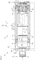
- FIG. 8 is a longitudinal sectional view of work assembly 28 with milling drum 32 of FIG Figure 1 shown in a sectional plane containing the axis of rotation R of the milling drum.
- Figure 2 also shows parts of the milling drum box 30.
- the milling drum 32 comprises an essentially cylindrical milling drum tube 42, on the radially outer side of which chisel holders or chisel change holders 33a with milling chisels 33b exchangeably received are provided in a manner known per se. Only one copy of these is shown for the sake of clarity.
- a dot-dash line 44 indicates the effective diameter (cutting circle cylinder) of the milling drum 32, defined by the milling cutter tips of the milling cutter 33b.
- the working assembly 28 comprises a drive formation 46 with an inner tube 48, a support cone 50 and a part 52a of a gear housing 52 that is rotatable relative to the machine frame 12 A of the drive formation 46 is connected.
- the drive axis A of the drive formation 46 and the axis of rotation R of the milling drum 32 are coaxial.
- Working group 28 is in Fig. 2 in a reference state ready for rotation about the drive axis A.
- the milling drum 32 is connected to the drive formation 46 of the working assembly 28 to transmit torque.
- the milling drum 32 surrounds the drive formation 46 radially on the outside.
- gear housing 52 a speed-reducing and torque-converting planetary gear is received.
- Right part 52a of the gear housing 52 is coupled to a ring gear of a planetary gear for common rotation.
- An in Figure 2 The left part 52b of the gear housing 52 is fixed to the supporting structure and consequently part of the machine body 13 fixed to the machine frame.
- the milling drum tube 42 is supported by a negative-conical counter-support cone 51 on the support cone 50 of the drive formation 46.
- the drive formation 46 is connected to a drive torque transmission arrangement 54 which, in the example shown, includes a belt pulley 55, among other things.
- the pulley 55 is provided with an in Figure 2 Not shown, the input shaft of the planetary gear in the gear housing 52 is connected.
- the input shaft connected to the belt pulley 55 for common rotation runs through a shaft tunnel 56 which is fixed to the supporting structure in the illustrated embodiment and which is rigidly connected to the transmission housing part 52b.
- the drive formation 46 together with the assembly of gear housing part 52b and shaft tunnel 56 fixed to the supporting structure, forms a drive assembly 47 which protrudes axially into the milling drum 32 from a drive axial end region 28a of the working assembly 28.
- the milling drum 32 preferably projects beyond the drive formation 46 as the part of the drive assembly 47 that is rotatable relative to the milling drum box 30 as the support structure and consequently to the machine frame 12 axially on both sides.
- the drive assembly 47 and with it the drive formation 46, is mounted in the area of the shaft tunnel 56 on a first support structure area 30c of the milling drum box 30. More precisely, the drive formation 46 with the rotatable gear housing part 52a is supported by a first pivot bearing 57 arranged between the rotatable gear housing part 52a and the gear housing part 52b fixed to the machine frame on the gear housing part 52b fixed to the machine frame and thus on the first support structure area 30c.
- the first pivot bearing 57 is in Fig. 2 only shown by dashed lines and symbolically.
- the first rotary bearing 57 forms a fixed bearing of the drive formation 46.
- the axial longitudinal end 46a of the drive formation 46 which is closer to the belt pulley 55, is therefore also referred to as the longitudinal end 46a on the fixed bearing side.
- the milling drum 32 extends axially along its axis of rotation (milling axis) R, which in the operationally ready state coincides with the drive axis A, between the axis of rotation (milling axis) R in FIG Figure 2
- the drive axial end area 28a which is closer to the drive torque transmission arrangement 54, and a locking axial end area 28b of the drive assembly 28 opposite the drive axial end area 28a.
- the locking screw 78 is part of the working assembly 28.
- the drive formation 46 has a support ring 58 and an end cover 60 connected to the support ring 58 as an end face component of the present application.
- the support ring 58 is in the illustrated embodiment welded to the inner tube 48.
- the cover 60 can also be welded to the support ring 58 or alternatively screwed. It is connected to the support ring 58 and the inner tube 48 for common rotation about the drive axis A.
- the support ring 58 and the radially outer regions of the cover 60 can be designed in different ways. Their shape is not essential. It is also conceivable to omit the support ring 58 and to connect the cover 60 directly to the inner tube 48, in particular to weld it.
- a hydraulic cylinder 62 is received in the interior 49 of the drive formation 46, the hydraulic cylinder axis of which is arranged coaxially to the drive axis A of the drive formation 46.
- the hydraulic cylinder 62 can be supplied with hydraulic fluid by means of a hydraulic connection line 64 through an energy passage opening 66 in the cover 60.
- the hydraulic connection line 64 ends at its longitudinal end remote from the hydraulic cylinder 62 in a coupling formation 68, which can be connected to supply the hydraulic cylinder 62 with a counter coupling formation of a supply line (not shown) in order to extend the piston rod 63 from the hydraulic cylinder 62 and retract it again to be able to.
- a coupling formation 68 which can be connected to supply the hydraulic cylinder 62 with a counter coupling formation of a supply line (not shown) in order to extend the piston rod 63 from the hydraulic cylinder 62 and retract it again to be able to.
- two hydraulic connection lines 64 can be provided, one for each direction of movement of the piston rod 63.
- the milling drum 32 can be axially pushed away from the drive formation 46 for dismantling or pulled onto the drive formation 46 for assembly.
- a connecting ring 70 is arranged radially on the inside on the milling drum tube 42 and is connected to the milling drum tube 42 for common rotation, in the example shown by a welded connection.
- the milling drum tube 42 is rigidly connected to a connecting flange 74 via the connecting ring 70 by means of screw bolts 72.
- the connecting ring 70 and the connecting flange 74 together form a connecting structure 73 of the milling drum 32 mentioned in the introduction to the description.
- a bearing journal 74a is provided on the connecting flange 74, screwed or welded to the connecting flange 74 or preferably formed in one piece therewith, which, starting from a connecting area of the connecting flange 74 with the connecting tube 70, axially towards the securing axial end area 28b or from the drive axial end area 28a away, protrudes.
- the connecting flange can be connected directly to the milling drum tube, in particular welded, if it is dimensioned accordingly, without a connecting ring.
- the bearing pin can be designed separately from the connecting flange and can be attached to it, in particular screwed on in a detachable manner.
- a second pivot bearing 76 which supports the drive formation 46 and is mounted for rotation about the drive axis A, is arranged on the bearing journal 74a to form a floating bearing of the pivot bearing.
- Both pivot bearings 57 and 76 are designed as roller bearings in the illustrated embodiment.
- the second pivot bearing 76 together with the bearing journal 74a and a bearing sleeve 86 arranged on the inner ring of the second pivot bearing 76, is part of a pivot bearing arrangement 77 with the bearing sleeve 86 a pivot bearing assembly 85 which can only be moved jointly during normal operation.
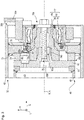
- the second pivot bearing 76 can, for example, be in a side plate or side door 30a (see FIG. Figure 3 ) be included as a second support structure area.
- the side door 30a is part of the milling drum box 30 and lies axially opposite the milling drum 32 on the securing axial end region 28b on the end face.
- a component 30b rigidly connected to such a side door 30a as the second support structure area is shown as a bearing surface for the outer bearing ring of the second pivot bearing 76.
- the side door 30a is preferably provided pivotably on the machine frame 12 in order to be able to make the drive formation 46 and / or the milling drum 32 in the interior of the milling drum box 30 accessible by simply pivoting it open and closed.
- the side door 30a is preferably pivotable about a pivot axis that is parallel to the machine height direction H, since then the pivoting of the side door 30a does not have to take place in any pivoting direction against the force of gravity.
- the pivot bearing assembly 85 is preferably mounted on the side door 30a in such a way that the pivot bearing assembly 85 can be pivoted together with the side door 30a. Opening the side door 30a pulls the pivot bearing assembly 85, that is to say the second pivot bearing 76 together with the bearing sleeve 86, axially away from the bearing journal 74a.
- the distance of the side door pivot axis from the side door 30a is preferably greater than the radius of the in FIG Figure 2 shown circular cutting cylinder of the milling drum 32, so that the circular path of the rotary bearing assembly 85 when pivoting together with the side door 30a has the largest possible radius and thus the smallest possible curvature. This makes it easier to pull off or push on the pivot bearing assembly 85 from the bearing pin 74a or onto this bearing pin 74a.
- the hydraulic cylinder 62 with its piston rod 63 is in Figure 3 omitted for the sake of clarity.
- the screw bolts 72 for connecting the connecting flange 74 to the connecting ring 70 are also not shown for the sake of clarity.
- a centering formation 60a in the form of a centering pin is formed on the cover 60, preferably in one piece with it, which protrudes from the cover 60 in the direction of the longitudinal end 46a of the drive formation 46 on the fixed bearing side or away from the drive axial end region 28a of the working assembly 28 to the second support structure region 30a.
- the centering pin 60a protrudes into a counter-centering formation 74b formed as a centering recess on the connecting flange 74 and thus centers the milling drum tube 42, which is rigidly connected to the connecting flange 74, with respect to the drive axis A.
- the cover 60 has a central, axially penetrating recess 60b, which is from the piston rod 63 in Figure 2 is axially enforceable.
- the milling drum 32 is thus supported on the counter support cone 51 and on the connecting flange 74 coaxially to the drive axis A on the drive formation 46.
- the recess 60b in the centering pin 60a is provided with an internal thread into which the central securing screw 78 is screwed.
- the centering pin 60a can pass through the connecting flange 74 and protrude axially from the cover 60 of the drive formation 46. Then the centering pin 60a would be the assembly-side bearing formation.
- a screw head 78b clamps the bearing journal 74a and with it the connecting flange 74 and in turn with it the connecting ring 70 and the milling drum tube 42 axially against the support cone 50 of the drive formation 46.
- the milling drum 32 can be moved axially with the central locking screw 78 into its operating position.
- transmission components 80 provided on the cover 60 at a radial distance from the drive axis A in the exemplary form of pins can get into recesses 74c of the connecting flange 74 provided for this purpose, in order to enable the cover 60 with the connecting flange 74 to transmit torque to couple between the drive formation 46 and the milling drum 32.
- the milling drum 32 can also be pushed onto the drive formation 46 through the pivotable side door 30a. During this pushing-on, not only is the counter-centering formation 74b pushed onto the centering pin 60a, but preferably the pivot bearing assembly 85 is pushed onto the bearing pin 74a.
- the soil cultivating machine 10 preferably has an actuator which supports pivoting of the side door 30a at least in one direction of movement and at least in a movement area containing the closed position. Particularly preferably, this is an end region of movement when the side door 30a is moved into the closed position.
- an actuator can, for example, have one or more piston-cylinder arrangements.
- the cylinder is preferably hinged to the machine frame 12.
- the side door 30a When the piston rod is extended, when the side door 30a has sufficiently approximated an engagement formation of the piston rod, the side door 30a can be brought into engagement with the engagement formation of the piston rod, preferably in a form-locking engagement that transmits a particularly high force, so that then the one or more piston-cylinder arrangements at least support the rest of the closing movement of the side door 30a, and preferably carry them out automatically.
- the actuator can support the pivoting movement of the side door 30a together with the pivot bearing assembly 85 also in a movement starting area of the pivoting movement of the side door 30a from the closed position to the access position, or even execute over which movement starting area the pivot bearing assembly 85 is withdrawn from the bearing pin 74a.
- the actuator can also be an electromechanical actuator.
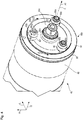
- the viewer of Figure 4 looks at the end face 60c of the cover 60, from the center of which the centering pin 60a protrudes and which is surrounded at a radial distance, for example, by three transmission components 80 arranged equidistant from one another in the circumferential direction. That’s in Figure 3
- the upper transmission component is formed with a driver formation 88 on its freely cantilevered longitudinal end remote from the end face 60c.
- this upper transmission component 80 ' is designed with a driver formation 88, which is why it is designated as transmission component 80' with an apostrophe to distinguish it from the other two transmission components 80.
- All transmission components 80 and 80 ' are fastened to the cover 60 by a screw 80a penetrating them centrally. While a collar 80b of the unmodified transmission components 80 which surrounds the head of the screw 80a ends with an end surface orthogonal to the drive axis A, the transmission component 80 'having the driver formation 88 projects axially further from the end face 60c, with a circumferential section of the fastening screw 80a surrounding collar 80b' is designed as a driver formation 88 (see also Figure 5 ).
- the drive formation 46 can only be driven to rotate in one direction of rotation by the rotary drive described above for soil-removing machining, that is, that in FIG Figure 4 with U1 designated first circumferential direction.
- the driver formation 88 has a driver surface 88a, in the example shown a flat driver surface 88a, which points in the first circumferential direction U1.
- the flat driver surface 88a preferably lies in a plane which contains the drive axis A.
- an adjustment surface 88b pointing mainly in the axial direction, which, as in FIG Figure 7 is shown, is inclined with respect to a reference plane BE orthogonal to the drive axis A in such a way that with increasing distance from the driver surface 88a in the second circumferential direction U2 it approaches the drive axial end area 28a of the working assembly 28 or also the longitudinal end area 46a of the drive formation 46 on the fixed bearing side.
- FIGS Figures 6 and 7th a torque-transmitting engagement of the driver formation 88 with a driver counter-formation 90 on the bearing sleeve 86 is shown.
- FIGS Figures 6 and 7th only the transmission component 80 'having the driver formation 88, its fastening screw 80a, the driver counter-formation 90 and the bearing sleeve 86 carrying it are shown.
- FIGS Figures 6 and 7th In connection with the previously explained Figures 2 to 5 however, it is clearly clear how those in the Figures 6 and 7th Components shown on the milling drum box 30 or on the road milling machine 10 are arranged.
- the driver counter-formation 90 has a, preferably again flat, driver counter surface 90a pointing in the second circumferential direction U2, which is in contact with the driver surface 88a in torque-transmitting contact engagement.
- a counter-adjusting surface 90b likewise pointing mainly in the axial direction, extends in the first circumferential direction U1, which, as also in FIG Figure 7 It can be seen that it is inclined relative to the reference plane BE in such a way that it moves away from the axial drive end region in the second circumferential direction U2 with increasing distance from the driving counter surface 90a 28a of the working assembly 28 axially as well as from the longitudinal end 46a of the drive assembly 46 on the fixed bearing side.
- the adjustment surface 88b and the adjustment counter surface 90b both point in axial directions, but in opposite axial directions A1 and A2 (see Fig. 7 ).
- driver counter-surface 90a and adjusting counter-surface 90b are formed on a projection component 90c, which is inserted as a separate component into a recess 90d in the bearing sleeve 86 and is detachably fastened there by three screws, for example.
- the depression 90d is a functional component of the driver counter-formation 90.
- the torque transmitted from the driver formation 88 to the driver counter-formation 90 can thus be transmitted both via the fastening screws of the projection component 90c and via the flanks of the recess 90d from the projection component 90c to the bearing sleeve 86 and thus to the pivot bearing assembly 85.
- the indentation 90d can provide a planar fastening surface for the arrangement of the projection component 90c.
- the projection component 90c can also be welded to the bearing sleeve 86.
- a releasable attachment for replacing worn protrusion components is preferred.
- the transmission component 80 ' can be quickly, easily and safely replaced by an unworn transmission component 80' by loosening its single fastening screw 80a.
- the flat driving counter surface 90a is also preferably located in a plane containing the drive axis A.
- angles ⁇ and ⁇ are preferably at least 25 °, better still at least 30 °, in order to avoid self-locking in the event that the adjustment surface 88b and the adjustment counter-surface 90b abut one another and to ensure that when the driver formation 88 and the driver counter-formation 90 during an experiment, those described above and in the Figures 2 and 3 Establish reference state shown, not only overlap each other in the circumferential direction, but are acted upon with force in the axial direction, driven by this axial force at the contact engagement of adjustment surface 88b and adjustment counter surface 90b are driven for relative rotation and can slide past each other during an axial movement towards each other. This prevents damage to the driver formation 88 and the driver counter-formation 90 in the event of a collision.
- FIG Figure 7 the movement space of the driver surface 88a is shown with reference number 92 and the movement space of the counter-drive surface 90a is shown with reference number 94. These are those spaces 92 and 94 which sweep over the associated surfaces 88a and 90a during a rotation about the drive axis A.
- the driver surface 88a also comes into contact with the driver counter surface 90a when the two surfaces are arranged at a distance from one another in the circumferential direction around the drive axis A immediately after the reference state has been established and there is a relative rotation between the bearing pin 74a and the during a machining operation Bearing sleeve 86 around the drive axis A occurs.
- the adjustment surface 88b and the adjustment counter surface 90b such a relative rotation between the bearing journal 74a and the bearing sleeve 86 cannot even amount to one revolution.
- the driver formation 88 can be arranged on the milling drum, preferably on the connecting structure 73.
- the driver formation can preferably be detachably arranged on the connecting flange, for example in a recess.
- FIG Figure 8 Such a second embodiment is shown in FIG Figure 8 shown. Identical and functionally identical components and component sections as in the first embodiment are provided with the same reference numerals in the second embodiment, but increased by the number 100. The second embodiment will only be described below to the extent that it differs from the first embodiment.
- the driver formation 188 is arranged on the connecting structure 173.
- the bearing journal is designed as a separate component separate from the connecting flange 174.
- the separate journal component and the journal itself are in Figure 8 covered by the bearing sleeve 186.
- the driver formation 188 comprises a projection component 188c, on which the driver surface 188a and the adjustment surface 188b are designed and aligned in the manner described above, and which is inserted into a recess 188d of the driver formation 188 and detachably fixed there with screws as intended.
- the depression 188d is formed in an end face of the connecting flange 174.
- the driver counter-formation 190 corresponds to the driver counter-formation 90 of the first embodiment.
- the projection components 90c and 188c can be identical, so that only a single type of projection component needs to be manufactured to form an engagement assembly comprising a driver formation and a driver counter-formation.
Landscapes
- Engineering & Computer Science (AREA)
- Mining & Mineral Resources (AREA)
- Architecture (AREA)
- Civil Engineering (AREA)
- Structural Engineering (AREA)
- Mechanical Engineering (AREA)
- General Engineering & Computer Science (AREA)
- Geochemistry & Mineralogy (AREA)
- General Life Sciences & Earth Sciences (AREA)
- Geology (AREA)
- Life Sciences & Earth Sciences (AREA)
- Mounting Of Bearings Or Others (AREA)
- Soil Working Implements (AREA)
- General Details Of Gearings (AREA)
- Agricultural Machines (AREA)
- Rolling Contact Bearings (AREA)
- Road Repair (AREA)
Abstract
Description
- Die vorliegende Erfindung betrifft eine Bodenbearbeitungsmaschine, wie etwa Straßenfräse, Recycler, Stabilisierer oder Surface-Miner, umfassend eine Tragstruktur und eine zur Bodenbearbeitung um eine Antriebsachse relativ zur Tragstruktur drehbar an der Tragstruktur gelagerte Arbeitsbaugruppe, wobei die Antriebsachse eine längs der Antriebsachse verlaufende axiale Richtung, eine orthogonal dazu verlaufende radiale Richtung und eine um die Antriebsachse umlaufende Umfangsrichtung definiert, wobei in einem für eine Drehung der Arbeitsbaugruppe um die Antriebsachse bereiten Bezugszustand die Arbeitsbaugruppe an einem Antriebsaxialendbereich mittels eines ersten Drehlagers drehbar an einem ersten Tragstrukturbereich gelagert ist und an einem in axialer Richtung vom Antriebsaxialendbereich entfernt gelegenen Sicherungsaxialendbereich mittels einer Drehlageranordnung drehbar an einem zweiten Tragstrukturbereich gelagert ist, wobei die Drehlageranordnung ein zweites Drehlager, eine mit der Arbeitsbaugruppe verbundene baugruppenseitige Lagerformation und eine mit der Tragstruktur verbundene strukturseitige Lagerformation aufweist, wobei der Sicherungsaxialendbereich als die baugruppenseitige Lagerformation eine Formation aus Lagerzapfen und Lagerhülse aufweist und wobei der zweite Tragstrukturbereich als die strukturseitige Lagerformation die jeweils andere Formation aus Lagerzapfen und Lagerhülse aufweist, wobei im Bezugszustand die Lagerhülse den Lagerzapfen umgibt, wobei sowohl der Lagerzapfen als auch die Lagerhülse im Bezugszustand relativ zum zweiten Tragstrukturbereich um die Antriebsachse drehbar angeordnet sind, und wobei der Lagerzapfen und die Lagerhülse zu Wartungs-, Umrüst- und Montagezwecken bestimmungsgemäß axial voneinander entfernbar und dadurch voneinander trennbar sind.
- Die vorliegende Erfindung betrifft außerdem eine zur Verbindung mit einem Maschinenrahmen einer Bodenbearbeitungsmaschine ausgebildete Tragstruktur, insbesondere realisiert als Fräswalzenkasten, welche eine Mehrzahl von Verbindungsformationen zur bestimmungsgemäß lösbaren Verbindung mit einem Maschinenrahmen einer Bodenbearbeitungsmaschine aufweist. Die Tragstruktur umfasst eine zur Bodenbearbeitung um eine Antriebsachse relativ zur Tragstruktur drehbar an der Tragstruktur gelagerte Arbeitsbaugruppe und ist im Übrigen wie im vorstehenden Absatz angegeben ausgebildet.
- Eine gattungsgemäße Bodenbearbeitungsmaschine in Gestalt einer Straßenfräse und eine gattungsgemäße Tragstruktur in Gestalt eines Fräswalzenkastens sind aus der
EP 3406798 A1 bekannt. - Der zweite Tragstrukturbereich der bekannten Bodenbearbeitungsmaschine ist als Wartungsklappe oder Wartungstüre des Fräswalzenkastens um eine im Wesentlichen zur Gierachse der Bodenbearbeitungsmaschine parallele Schwenkachse schwenkbar, um durch Verschwenken der Wartungstüre eine Zugänglichkeit einer im Fräswalzenkasten aufgenommenen Fräswalze oder einer sie tragenden Antriebsformation als Bestandteile einer bekannten Arbeitsbaugruppe zu erreichen. Die Fräswalze kann bei geöffneter Wartungstüre axial von der sie tragenden Antriebsformation abgezogen und beispielsweise durch eine andere Fräswalze ersetzt werden.
- Der Lagerzapfen und die Lagerhülse sind derart gestaltet, dass beim Öffnen der Wartungstüre die strukturseitige Lagerformation, im bekannten Fall eine Lagerhülse, von der baugruppenseitigen Lagerformation, im bekannten Fall ein Lagerzapfen, mit der Schwenkbewegung der Wartungstüre axial abgezogen wird. Aufgrund der Schwenkbewegung ist die Abziehbewegung der Lagerhülse vom Lagerzapfen keine reine axiale Relativbewegung, sondern der überwiegend axialen translatorischen Komponente der Abziehbewegung ist eine betragsmäßig geringere radiale translatorische und eine rotatorische Bewegungskomponente der Lagerhülse überlagert.
- Aufgrund der vorteilhaft einfachen und schnellen Trennbarkeit der strukturseitigen und der baugruppenseitigen Lagerformation der Drehlageranordnung sind die genannten Lagerformationen im Bezugszustand nur reibschlüssig miteinander zur gemeinsamen Drehbewegung um die Antriebsachse gekoppelt. Im Bodenbearbeitungsbetrieb der Bodenbearbeitungsmaschine können in bestimmten Betriebssituationen mit kurzzeitig erhöhter radialer Last der Drehlagerung der Arbeitsbaugruppe, etwa beim Anfahren der Arbeitsbaugruppe oder/und beim Ansetzen der Arbeitsbaugruppe an den zu bearbeitenden Boden oder/und beim Verändern einer Eingriffstiefe der Arbeitsbaugruppe orthogonal zur Antriebsachse, so hohe Belastungen an der Drehlageranordnung auftreten, dass es zu einer unerwünschten Relativdrehung der strukturseitigen und der baugruppenseitigen Lagerformation relativ zueinander kommt. Die derart auftretende Relativdrehung kann an wenigstens einer der Lagerformationen unerwünscht erhöhten Verschleiß bewirken.
- Es ist daher Aufgabe der vorliegenden Erfindung, die Lagerung der Arbeitsbaugruppe an der Drehlageranordnung mit den voneinander bestimmungsgemäß trennbaren Lagerformationen zu verbessern und hierdurch möglichen erhöhten Verschleiß zu vermeiden.
- Die vorliegende Erfindung löst diese Aufgabe an einer Bodenbearbeitungsmaschine der eingangs genannten Art dadurch, dass die Arbeitsbaugruppe eine Mitnehmerformation mit einer in einer ersten Umfangsrichtung um die Antriebsachse weisenden Mitnehmerfläche aufweist und dass die strukturseitige Lagerformation eine Mitnehmergegenformation mit einer in einer zur ersten entgegengesetzten zweiten Umfangsrichtung um die Antriebsachse weisenden Mitnehmergegenfläche aufweist, wobei sich im Bezugszustand die Bewegungsräume der Mitnehmerfläche und der Mitnehmergegenfläche um die Antriebsachse überlappen.
- Die vorliegende Erfindung löst diese Aufgabe mit gleichen Mitteln an einer eingangs genannten Tragstruktur für eine solche Bodenbearbeitungsmaschine; das ist eine Tragstruktur gemäß Anspruch 15. Da die Erfindung an der Tragstruktur der Bodenbearbeitungsmaschine realisiert ist und die Tragstruktur bestimmungsgemäß lösbar mit der Bodenbearbeitungsmaschine verbunden sein kann, gilt die nachfolgende Beschreibung und Weiterbildung der vorliegenden Erfindung sowohl für die Bodenbearbeitungsmaschine als auch für die Tragstruktur für sich alleine genommen. Die Tragstruktur ist bevorzugt eine die Arbeitsbaugruppe an mehreren Seiten umgebende Hülle, wie etwa ein an sich bekannter Fräswalzenkasten, welcher eine Fräswalze oder wenigstens eine zur bestimmungsgemäß lösbaren Kopplung mit einer Fräswalze ausgebildete Antriebsformation um die Antriebsachse drehbar gelagert aufweist. Die Tragstruktur kann grundsätzlich jedoch jede beliebige Struktur sein, welche das erste Drehlager und die Drehlageranordnung trägt.
- Die vorliegende Erfindung wird, sofern nicht ausdrücklich im Einzelfall etwas Abweichendes ausgesagt ist, in dem eingangs definierten Bezugszustand beschrieben, in welchem die Arbeitsbaugruppe zur Drehung um die Antriebsachse bereit ist.
- Die Wartungs-, Umrüst- und Montagezwecke, zu welchen der Lagerzapfen und die Lagerhülse axial vorrangig voneinander entfernbar sind, betreffen eine Wartung oder/ und Umrüstung oder/und eine Montage anderer Bauteile als des zweiten Drehlagers der Drehlageranordnung. Das zweite Drehlager kann ein Wälzlager oder ein Gleitlager umfassen oder sein. Oben bereits angegeben, betreffen die Wartungs-, Umrüst- und Montagezwecke Arbeiten an der Arbeitsbaugruppe, etwa die Demontage einer Fräswalze von einer Antriebsformation oder/und die Montage einer Fräswalze auf eine Antriebsformation.
- Durch die Anordnung der genannten Mitnehmerformation und Mitnehmergegenformation mit in entgegengesetzte Umfangsrichtung um die Antriebsachse weisenden Flächen: Mitnehmerfläche und Mitnehmergegenfläche, deren um die Antriebsachse verlaufenden Bewegungsräume sich überlappen, können die Mitnehmerfläche und die Mitnehmergegenfläche, und folglich die Mitnehmerformation und die Mitnehmergegenformation, einander längs einer Umfangsbahn um die Antriebsachse nicht passieren. Somit ist selbst dann, wenn die Mitnehmerfläche und die Mitnehmergegenfläche beim Verbinden der strukturseitigen und der baugruppenseitigen Lagerformation der Drehlageranordnung in Umfangsrichtung um die Antriebsachse maximal weit voneinander entfernt liegen, nur eine Relativdrehung der beiden Lagerformationen von weniger als einer ganzen Umdrehung möglich, bis die Mitnehmerfläche in Anlageeingriff mit der Mitnehmergegenfläche gelangt und die Lagerformationen der Drehlageranordnung durch den so erzielten Formschlusseingriff synchron und ohne Relativdrehung um die Antriebsachse drehen. Sollte eine Relativdrehung von weniger als 360° gewünscht sein, können über den Umfang verteilt mehrere Mitnehmerformationen und/oder Mitnehmergegenformationen vorgesehen sein. Zur Sicherstellung einer einheitlichen Belastung der Formationen können gemäß einer Weiterbildung der vorliegenden Erfindung ebenso viele Mitnehmerformationen wie Mitnehmergegenformationen angeordnet sein. Bevorzugt ist eine Mehrzahl von Mitnehmerformationen oder/und Mitnehmergegenformationen in Umfangsrichtung äquidistant um die Antriebsachse verteilt angeordnet, sodass bei der Herstellung des Bezugszustands nicht auf die Relativorientierung der Mitnehmerformationen und Mitnehmergegenformationen relativ zueinander geachtet zu werden braucht. Aus Gründen der bevorzugten äquidistanten Anordnung ist der Winkelabstand zwischen zwei benachbarten Mitnehmerformationen bzw. Mitnehmergegenformationen ein ganzzahliger Bruchteil von 360°.
- Der Bewegungsraum einer Fläche ist dabei jener Raum, welcher von einer Fläche: Mitnehmerfläche oder Mitnehmergegenfläche, während einer Drehung um die Antriebsachse durchlaufen wird.
- Da in der Regel der Pfad des Antriebsdrehmoments von Arbeitsbaugruppe zur strukturseitigen Lagerformation verläuft und da weiter die Arbeitsbaugruppe in der Regel nur in einem Drehsinn zur Drehung antreibbar ist, ist die erste Umfangsrichtung, in welcher die Mitnehmerfläche weist, die Umfangsrichtung, in welche die Arbeitsbaugruppe zur Drehung antreibbar ist.
- Die Bodenbearbeitungsmaschine weist als Drehantrieb der Arbeitsbaugruppe bevorzugt einen Antriebsmotor auf, von welchem ausgehend ein Antriebsdrehmoment auf die Arbeitsbaugruppe übertragbar ist. Zum Antrieb der Arbeitsbaugruppe mit einer geeigneten Drehzahl oder einem geeigneten Drehzahlbereich kann im DrehmomentÜbertragungspfad vom Antriebsmotor bis zur Arbeitsbaugruppe wenigstens ein Getriebe, insbesondere Planetengetriebe, vorgesehen sein. Der Antriebsstrang vom Antriebsmotor bis zur Arbeitsbaugruppe kann ein Zugmittelgetriebe, insbesondere einen Riementrieb, und das genannte Planetengetriebe aufweisen, aus Bauraumerwägungen bevorzugt in der genannten Reihenfolge längs des Drehmoment-Übertragungspfads. Zur Bereitstellung von ausreichend hydraulischer Energie kann im Antriebsstrang zusätzlich ein Pumpenverteilergetriebe angeordnet sein, bevorzugt zwischen Antriebsmotor und Zugmittelgetriebe. Das im Drehmoment-Übertragungspfad vom Antriebsmotor bis zur Arbeitsbaugruppe letzte Getriebe, insbesondere das oben genannte Planetengetriebe, kann wenigstens abschnittsweise in einer dauerhaft mittels des ersten Drehlagers der Tragstruktur drehbar gelagerten Antriebsformation angeordnet sein.
- Das Getriebe selbst kann als Planetengetriebe das erste Drehlager aufweisen. Ein erster Teil des Getriebegehäuses kann ortsfest an der Tragstruktur festgelegt sein und ein zweiter Teil des Getriebegehäuses kann relativ zum ersten Getriebegehäuseteil um die Antriebsachse drehbar am ersten Getriebegehäuseteil gelagert sein. Der zweite Getriebegehäuseteil kann drehfest mit der Antriebsformation gekoppelt oder/und Teil der Antriebsformation sein.
- Das erste Drehlager ist daher bevorzugt ein sogenanntes Festlager der Drehlagerung der Arbeitsbaugruppe. Als Festlager weist das erste Drehlager kein axiales Bewegungsspiel relativ zu den mit ihm verbundenen Komponenten: erster Tragstrukturbereich und Arbeitsbaugruppe, auf. Das Festlager bleibt an der Bodenbearbeitungsmaschine bzw. an der Tragstruktur mit Ausnahme von unvermeidlichem Verschleiß über seine Betriebslebensdauer hinweg in der Regel unverändert. Die Drehlageranordnung bildet dagegen ein Loslager der Drehlagerung der Arbeitsbaugruppe, welches bestimmungsgemäß eine axiale Relativbewegung zwischen dem zweiten Tragstrukturbereich und der Arbeitsbaugruppe zulässt. Die Drehlageranordnung ist sogar bestimmungsgemäß zur wiederholten Trennung und erneuten Verbindung seiner oben genannten Lagerformationen ausgebildet.
- Bevorzugt ist die strukturseitige Lagerformation die Lagerhülse. Um die Bauteilanzahl gering zu halten, kann die Lagerhülse grundsätzlich der Innenring des bevorzugt als Wälzlager ausgebildeten zweiten Drehlagers sein, wenngleich dies aufgrund der hohen Härte und der damit verbundenen schlechten Bearbeitbarkeit eines Wälzlager-Innenrings nicht bevorzugt ist. Bevorzugt ist die strukturseitige Lagerformation eine von einem Innenring des bevorzugt als Wälzlager ausgebildeten zweiten Drehlagers mittelbar oder unmittelbar getragene Lagerhülse. Da die Lagerhülse bevorzugt durch eine Schwenkbewegung des zweiten Tragstrukturbereichs auf den die baugruppenseitige Lagerformation bildenden Lagerzapfen aufschiebbar und von diesem abziehbar sein soll, ist die Lagerhülse vorzugsweise mit einer sich in Richtung vom Antriebsaxialendbereich weg verjüngenden Ausnehmung ausgebildet. Die Lagerhülse ist somit bevorzugt grob trichterförmig. Aus denselben Gründen ist der folglich bevorzugt die baugruppenseitige Lagerformation bildende Lagerzapfen vorzugsweise zu seinem auskragenden Längsende hin sich verjüngend ausgebildet.
- Das zweite Drehlager ist funktionell bevorzugt zwischen dem zweiten Tragstrukturbereich einerseits und den beiden Lagerformationen andererseits angeordnet, sodass beide Lagerformationen relativ zum zweiten Tragstrukturbereich drehbar sind.
- Um während einer Bodenbearbeitung zwischen der Mitnehmerformation und der Mitnehmergegenformation unerwünschte Nebenkräfte mit Komponenten orthogonal zu einer einen Berührbereich von Mitnehmerfläche und Mitnehmergegenfläche durchsetzenden virtuellen Umfangskreisbahn vermeiden zu können, ist bevorzugt wenigstens eine Fläche aus Mitnehmerfläche und Mitnehmergegenfläche eben ausgebildet. Die ebene Fläche liegt bevorzugt in einer die Antriebsachse enthaltenden Ebene, sodass sie während einer Drehung um die Antriebsachse zu jeder Zeit orthogonal zu ihrer Bewegungsbahn orientiert ist. Die jeweils andere Fläche aus Mitnehmerfläche und Mitnehmergegenfläche kann eine an der ebenen Fläche aufliegende konvex gekrümmte Gestalt aufweisen, etwa als Kugelkalotte oder Ellipsoidkalotte, oder, und dies ist sowohl aus Gründen einfacher Fertigung als auch möglichst niedriger Flächenpressung bevorzugt, kann ebenfalls eben sein. Zur Vermeidung unerwünschter hoher Belastungen durch Flächenpressungen an der Berührstelle zwischen Mitnehmerfläche und Mitnehmergegenfläche liegen die Mitnehmerfläche und die Mitnehmergegenfläche im Anlageeingriff bevorzugt flächig aneinander an, sind also im Anlageeingriff parallel zueinander. Daher liegt bevorzugt auch die jeweils andere ebene Fläche aus Mitnehmerfläche und Mitnehmergegenfläche in einer die Antriebsachse enthaltenden Ebene.
- Wenngleich also unmittelbar nach Herstellung einer Verbindung der Lagerformationen miteinander längs einer Umfangskreisbahn um die Antriebsachse ein Abstand zwischen der Mitnehmerfläche und der Mitnehmergegenfläche bestehen kann, so ist eine Betriebssituation bevorzugt, bei welcher die Mitnehmerfläche und die Mitnehmergegenfläche sich in einem in Umfangsrichtung Kraft übertragenden Anlageeingriff befinden. So sie nicht von vornherein besteht, stellt sich diese Betriebssituation vorliegend dann, wenn es zu einer Relativdrehung zwischen den genannten Lagerformationen kommt, vorteilhaft von alleine ein.
- Zur sicheren Herstellung des oben beschriebenen Drehmoment übertragenden Anlageeingriffs zwischen der Mitnehmerfläche und der Mitnehmergegenfläche kann die Mitnehmergegenformation eine Einsenkung aufweisen, in welche ein Vorsprung der Mitnehmerformation eingreift. Alternativ kann die Mitnehmergegenformation einen Vorsprung aufweisen, welcher in Anlageeingriff mit einem Vorsprung oder einer Einsenkung der Mitnehmerformation steht oder bringbar ist. Weiter alternativ kann die Mitnehmergegenformation sowohl eine Einsenkung als auch einen Vorsprung aufweisen, etwa dann, wenn die Mitnehmergegenfläche an einem gesonderten Vorsprungsbauteil ausgebildet ist, welches in eine Einsenkung der strukturseitigen Lagerformation eingesetzt ist, um das Vorsprungsbauteil mit der Mitnehmergegenfläche möglichst dauerhaft und ortsfest an der strukturseitigen Lagerformation zu verankern. Das Vorsprungsbauteil mit der Mitnehmergegenfläche kann dann aus der Einsenkung heraus über die umgebende Oberfläche der Lagerformation hinaus vorstehen.
- Die Mitnehmergegenformation als Vorsprung oder Einsenkung kann einstückig mit der strukturseitigen Lagerformation zusammenhängend ausgebildet sein, beispielsweise durch urformende Herstellung mit gegebenenfalls anschließender Nachbearbeitung oder als Einsenkung auch nur durch entsprechende spanabhebende Bearbeitung. Flexibler und vor allem für eine Nachrüstung geeigneter kann die Mitnehmergegenformation als Vorsprungsbauteil mit der Lagerformation durch einen Fügevorgang verbunden sein. So kann die Mitnehmergegenformation mit der Lagerformation stoffschlüssig, insbesondere durch Schweißen, gegebenenfalls auch durch Löten oder Kleben, verbunden sein, was zu einer sehr hohen Verbindungsfestigkeit führt. Alternativ kann ein die Mitnehmergegenformation bildendes oder von der Mitnehmergegenformation umfasstes Vorsprungsbauteil, welches die Mitnehmergegenfläche aufweist, bestimmungsgemäß lösbar mit der Lagerformation verbunden sein, beispielsweise durch Verschrauben, sodass das die Mitnehmergegenfläche aufweisende Vorsprungsbauteil bei Erreichen eines vorbestimmten Verschleißzustandes gegen ein unverschlissenes Vorsprungsbauteil austauschbar ist.
- Ein hohes übertragbares Drehmoment bei gleichzeitig einfacher Austauschbarkeit der Mitnehmergegenfläche kann dadurch erhalten werden, dass die Mitnehmergegenformation einen Vorsprung, insbesondere ein Vorsprungsbauteil, aufweist, welcher bzw. welches in eine Einsenkung in der strukturseitigen Lagerformation eingesetzt und dort bestimmungsgemäß lösbar festgelegt ist. Bevorzugt ist der Vorsprung bzw. das Vorsprungsbauteil in einer festen, aber gleichzeitig lösbaren Verbindung durch Schrauben mit der strukturseitigen Lagerformation verbunden.
- Das oben zur Mitnehmergegenformation Gesagte trifft mutatis mutandis auch auf die Mitnehmerformation zu. Auch diese kann einen Vorsprung oder/und eine Einsenkung umfassen. Dem entsprechend kann auch die Mitnehmerformation ein Vorsprungsbauteil umfassen, welches in einer Einsenkung des sie tragenden Bauteils aufgenommen ist, um ein möglichst hohes Drehmoment von der - üblicherweise antreibenden - Mitnehmerformation zu der - üblicherweise angetriebenen - Mitnehmergegenformation übertragen zu können.
- Auch die Mitnehmerformation kann mit dem sie tragenden Bauteil bestimmungsgemäß lösbar, also etwa durch eine Verschraubung, oder bestimmungsgemäß unlösbar, also etwa durch Verschweißen, Verlöten, Verkleben und dergleichen, verbunden sein.
- Ein wesentlicher Unterschied zwischen der Mitnehmerformation und der Mitnehmergegenformation liegt darin, dass die Mitnehmergegenformation an der strukturseitigen Lagerformation angeordnet ist, um diese synchron mit der Arbeitsbaugruppe zu drehen, wohingegen die Mitnehmerformation jedoch nicht notwendigerweise an der baugruppenseitigen Lagerformation angeordnet sein muss, sondern an einer beliebigen geeigneten Stelle der Arbeitsbaugruppe zur gemeinsamen Bewegung mit dieser angeordnet sein kann. Selbstverständlich kann die Mitnehmerformation an der baugruppenseitigen Lagerformation angeordnet sein.
- Wie oben bereits dargelegt wurde, kann die Arbeitsbaugruppe eine Antriebsformation aufweisen, welche am Antriebsaxialendbereich mittels des ersten Drehlagers um die Antriebsachse drehbar am ersten Tragstrukturbereich gelagert ist und vom ersten Tragstrukturbereich weg axial auskragt. Auf die Antriebsformation kann axial von der Seite des Sicherungsaxialendbereichs her eine Arbeitsvorrichtung, wie etwa eine Fräswalze, aufgeschoben und zur gemeinsamen Drehung mit der Antriebsformation verbunden werden. Ebenso kann die Arbeitsvorrichtung von der Antriebsformation in entgegengesetzter Richtung axial abgezogen oder abgedrückt werden.
- Die Arbeitsbaugruppe kann nur die Antriebsformation aufweisen.
- Da die Antriebsformation dauerhaft am ersten Tragstrukturbereich drehbar gelagert ist, ist es vorteilhaft, wenn die Antriebsformation die Mitnehmerformation trägt. So ist die Mitnehmerformation stets an der Tragstruktur und damit an der sie aufweisenden Bodenbearbeitungsmaschine vorhanden.
- Üblicherweise ist im Bezugszustand der zweite Tragstrukturbereich axial mit Abstand von dem vom ersten Tragstrukturbereich auskragenden Längsende der Antriebsformation angeordnet. Um mit geringem baulichen Aufwand sicherstellen zu können, dass die Mitnehmerfläche einer an der Antriebsformation angeordneten Mitnehmerformation mit der Mitnehmergegenfläche der strukturseitigen Lagerformation in Drehmoment übertragenden Eingriff gelangen kann, ist es vorteilhaft, wenn die Antriebsformation an ihrem vom ersten Drehlager fernliegenden Längsende eine in axiale Richtung weisende Stirnfläche aufweist, wobei die Stirnfläche die Mitnehmerformation trägt. Zum einen stellt eine solche Stirnfläche eine ausreichend große Fläche zur Anordnung einer Mitnehmerformation bereit. Zum anderen kann die Stirnfläche bzw. ein die Stirnfläche aufweisendes Stirnflächenbauteil mit ausreichender Festigkeit zur Übertragung der erforderlichen Drehmomente ausgebildet sein.
- Die Stirnfläche ist bevorzugt orthogonal zur Antriebsachse angeordnet, jedoch muss dies nicht so sein. Die in axiale Richtung weisende Stirnfläche kann ebenso von der Antriebsachse nach radial außen gestuft oder/und konisch ausgebildet sein, wobei bevorzugt der halbe Öffnungswinkel des Stirnflächenkonus größer als 45° ist, um zu vermeiden, dass die Stirnfläche eine zu große axiale Erstreckung aufweist. Auch dann weist die Stirnfläche immer noch überwiegend in axiale Richtung.
- Die Antriebsformation kann einen Rohrabschnitt, insbesondere einen zylindrischen Abschnitt, aufweisen, dessen Rohr- bzw. Zylinderachse die Antriebsachse ist. In wenigstens einem Teil dieses Rohrabschnitts, vorzugsweise in einem dem ersten Tragstrukturbereich näher als dem zweiten Tragstrukturbereich gelegenen Rohrabschnitt kann wenigstens ein Teil des oben genannten Getriebes angeordnet sein.
- Der zylindrische Abschnitt kann an seinem vom ersten Drehlager fernliegenden auskragenden Längsende durch ein Stirnflächenbauteil teilweise oder bevorzugt ganz abgedeckt sein, sodass die Antriebsformation bevorzugt eine topfartige Formation umfasst, deren Boden durch das Stirnflächenbauteil gebildet ist.
- Wie bereits oben dargelegt wurde, ist die Antriebsformation zur Erfüllung unterschiedlicher Arbeitsaufgaben bevorzugt zur bestimmungsgemäß lösbaren Aufnahme einer Fräswalze ausgebildet. So kann die Antriebsformation zeitlich nacheinander eine Mehrzahl von Fräswalzen aufnehmen, welche sich hinsichtlich Art oder/und Anzahl oder/und Anordnung von daran angeordneten Bodenmaterial abhebenden Fräsmeißeln unterscheiden. Somit kann die Arbeitsbaugruppe die Arbeitsformation und die Fräswalze umfassen.
- Um eine Relativdrehung zwischen Antriebsformation und von dieser aufgenommener Fräswalze zu vermeiden, weist die Antriebsformation bevorzugt vorspringende Übertragungsbauteile auf, welche zur körperlichen Drehmomentübertragung auf eine an der Antriebsformation angeordnete Fräswalze ausgebildet sind. Üblicherweise wird am Antriebsaxialendbereich Drehmoment von einem Antriebsmotor der Bodenbearbeitungsmaschine in die Antriebsformation eingeleitet. Dann, wenn die Fräswalze an der Antriebsformation angeordnet ist und die Arbeitsbaugruppe sowohl die Antriebsformation als auch die Fräswalze aufweist, verläuft der Drehmoment-Übertragungspfad innerhalb der Arbeitsgruppe von der Antriebsformation zur Fräswalze.
- Um die Anzahl an Bauteilen der Arbeitsgruppe möglichst gering zu halten, weist bevorzugt wenigstens eines der Übertragungsbauteile die Mitnehmerformation auf.
- Im Bezugszustand, insbesondere in einem zur Bodenbearbeitung bereiten Bezugszustand, sind eine an der Antriebsformation aufgenommene Fräswalze und die Antriebsformation koaxial angeordnet. Die Fräswalze umfasst einen Fräswalzenmantel, welcher die Antriebsformation radial außen umgibt. Zur möglichst einfachen und sicheren Übertragung von Drehmoment von der Antriebsformation zur Fräswalze überragt die Fräswalze bevorzugt die Antriebsformation an dem vom Antriebsaxialendbereich fernliegenden Längsende der Antriebsformation.
- Dann, wenn das erste Drehlager zwischen den oben genannten zwei Getriebegehäuseteilen angeordnet ist, kann die Fräswalze zur Erzielung einer großen axialen Arbeitsbreite das erste Drehlager radial außen umgeben und axial in Richtung vom Sicherungsaxialendbereich weg überragen.
- An der Außenseite des Fräswalzenmantels ist eine Mehrzahl von Fräsmeißelhaltern angeordnet sind, welche dazu ausgebildet sind, Fräsmeißel aufzunehmen. Bevorzugt sind die Fräsmeißelhalter als Fräsmeißelwechselhalter mit einem am Fräswalzenmantel dauerhaft angeordneten mantelseitigen Halterbauteil und mit einem bestimmungsgemäß lösbar mit diesem verbindbaren Halter-Wechselbauteil ausgebildet. Wegen der hohen Verschleißbeanspruchung von Fräsmeißeln im Bodenbearbeitungsbetrieb sind auch die Fräsmeißel bevorzugt austauschbar in dem jeweiligen Fräsmeißelhalter angeordnet. Die Fräsmeißelhalter sind zur Unterstützung der Förderung von abgetragenem Bodenmaterial von der Arbeitsbaugruppe weg bevorzugt wendelförmig am Fräswalzenmantel angeordnet.
- Die Fräswalze ist bevorzugt an ihrem dem Antriebsaxialendbereich näher gelegenen Längsende an der Antriebsformation abgestützt. Dies ist dort besonders einfach und stabil möglich, da die Antriebsformation im Antriebsaxialendbereich am ersten Tragstrukturbereich gelagert ist und somit dort wegen der geringen axialen Auskraglänge vom ersten Tragstrukturbereich eine hohe Abstützsteifigkeit aufweist. Zur erneuten Abstützung der Fräswalze an der Antriebsformation mit axialem Abstand von der erstgenannten Abstützung kann die Fräswalze im Sicherungsaxialendbereich bevorzugt eine quer zur Antriebsachse verlaufende Verbindungsstruktur aufweisen. Bevorzugt liegt die Verbindungsstruktur im Bezugszustand zur oben genannten Stirnfläche axial benachbart, sodass ein vorteilhafter, möglichst großer Lagerabstand zwischen den beiden Abstützstellen der Fräswalze möglich ist. Die Stirnfläche der Antriebsformation kann beispielsweise einen axial auskragenden Zentrierzapfen aufweisen, an welchem die Fräswalze über die Verbindungsstruktur formschlüssig zentriert abgestützt ist.
- Die oben genannte von der Antriebsformation getragene Mitnehmerformation kann sich axial an der Verbindungsstruktur vorbei oder durch die Verbindungsstruktur hindurch erstrecken und so über die Verbindungsstruktur hinaus zur strukturseitigen Lagerformation vorstehen. Bevorzugt ist die sich an der Verbindungsstruktur vorbei oder durch diese hindurch erstreckende Mitnehmerformation an dem oben genannten Übertragungsbauteil ausgebildet. So kann ein sich axial mit der Verbindungsstruktur überlappender Abschnitt des Übertragungsbauteils Drehmoment von der Antriebsformation auf die Fräswalze übertragen und kann ein sich axial über die Verbindungsstruktur hinaus zum zweiten Tragstrukturbereich hin erstreckender Abschnitt des Übertragungsbauteils die Mitnehmerformation bilden und Drehmoment auf die strukturseitige Lagerformation übertragen. Bevorzugt ist die Mitnehmerformation ein axialer Endbereich eines von der Antriebsformation axial auskragenden Übertragungsbauteils. Ein solches Übertragungsbauteil kann beispielsweise durch einen auskragenden Bolzen oder Zapfen realisiert sein. Auch dieses Übertragungsbauteil, und damit verbunden die Mitnehmerformation, ist bevorzugt an der Antriebsformation bestimmungsgemäß lösbar angeordnet, etwa durch eine Schraube, insbesondere eine das Übertragungsbauteil zentral durchsetzende Schraube.
- Zusätzlich oder alternativ zur Antriebsformation kann die Fräswalze die Mitnehmerformation tragen. Da die Fräswalze als gesonderte Baueinheit mit der Antriebsformation verbindbar und von dieser lösbar ist, betrifft die vorliegenden Anmeldung auch eine Fräswalze, wie sie in dieser Anmeldung beschrieben und weitergebildet ist, mit einer Mitnehmerformation.
- Dann, wenn die Fräswalze die Mitnehmerformation trägt, oder wenigstens auch eine Mitnehmerformation trägt, kann die Mitnehmerformation an der oben genannten Verbindungsstruktur angeordnet sein. Die wie oben beschrieben bevorzugt quer, besonders bevorzugt orthogonal, zur Antriebsachse verlaufende Verbindungsstruktur kann den Fräswalzenmantel mit der baugruppenseitigen Lagerformation verbinden. Bevorzugt ist die baugruppenseitige Lagerformation ein Lagerzapfen, welcher auf der vom Antriebsaxialendbereich weg weisenden Seite axial in Richtung vom Antriebsaxialendbereich weg vorsteht. Auf der zum Antriebsaxialendbereich hinweisenden Seite der Verbindungsstruktur kann im Bereich des Lagerzapfens eine Ausnehmung gebildet sein, in welche im Bezugszustand der oben genannte Zentrierzapfen der Stirnseite der Antriebsformation einragt.
- Die Arbeitsbaugruppe kann wenigstens eine Sicherungsanordnung umfassen, etwa eine oder mehrere Sicherungsschrauben, mittels welcher die Fräswalze an der Antriebsformation im Bezugszustand gesichert ist. Damit die Fräswalze bestimmungsgemäß lösbar an der Antriebsformation aufgenommen werden kann, ist auch die wenigstens eine Sicherungsanordnung bestimmungsgemäß lösbar an der übrigen Arbeitsbaugruppe aufgenommen. Die Mitnehmerformation kann an der Sicherungsanordnung, insbesondere als Sicherungsschraube, angeordnet oder ausgebildet sein. Sofern die Sicherungsanordnung im Bezugszustand zusätzlich zu einer Sicherungsschraube eine von der Sicherungsschraube an der Antriebsformation oder/und an der Fräswalze festgelegte Unterlegscheibe aufweist, kann die Mitnehmerformation alternativ oder zusätzlich an der Unterlegscheibe angeordnet oder ausgebildet sein.
- Um die Anzahl an Bauteilen zur Bildung der Arbeitsbaugruppe gering zu halten, umfasst die Sicherungsanordnung bevorzugt eine Sicherungsschraube, welche in den oben genannten Zentrierzapfen der Antriebsformation derart eingedreht ist, dass ihre Schraubachse im Bezugszustand zur Antriebsachse koaxial ist.
- Die Mitnehmergegenformation kann insbesondere dann, wenn die Mitnehmerformation an der Sicherungsanordnung ausgebildet ist, an einem gesondert von der Lagerhülse oder einem Innenring des zweiten Drehlagers ausgebildeten Bauteil ausgebildet sein, welches bevorzugt bestimmungsgemäß lösbar mit der Lagerhülse oder einem Innenring des zweiten Drehlagers verbunden ist.
- Im Zweifel sind alle jene Bauteile Teil der Arbeitsbaugruppe, welche ausgehend vom Bezugszustand nach einem Abziehen der Lagerhülse vom Lagerzapfen noch mit der Antriebsformation verbunden sind.
- Im Gegensatz zu dem oben diskutierten Fall, dass die Mitnehmerformation und die Mitnehmergegenformation bei Herstellung des Bezugszustands in Umfangsrichtung um die Antriebsachse voneinander einen Abstand aufweisen, kann auch der Fall eintreten, dass die Mitnehmerformation die Mitnehmergegenformation einander bei der Herstellung des Bezugszustands in Umfangsrichtung überlappen. In diesem Falle kann diese Überlappung entweder als körperliche Barriere die Herstellung des Bezugszustands verhindern oder der kraftvolle Versuch einer Herstellung des Bezugszustands kann wenigstens eine der genannten Formationen beschädigen. Um im Überlappungsfall diese nachteiligen Folgen für die Bodenbearbeitungsmaschine bzw. die Tragstruktur zu vermeiden, kann vorgesehen sein, dass die Mitnehmerformation eine im Bezugszustand axial vom Antriebsaxialendbereich wegweisende Justierfläche aufweist und dass die Mitnehmergegenformation eine im Bezugszustand axial zum Antriebsaxialendbereich hinweisende Justiergegenfläche aufweist. Die Justierfläche ist bezüglich einer zur Antriebsachse orthogonalen Bezugsfläche derart geneigt, dass die Justierfläche sich mit längs der zweiten Umfangsrichtung zunehmendem Umfangsabstand von der Mitnehmerfläche dem Antriebsaxialendbereich annähert. Die Justiergegenfläche ist bezüglich der zur Antriebsachse orthogonalen Bezugsfläche derart geneigt, dass die Justiergegenfläche sich mit längs der ersten Umfangsrichtung zunehmendem Umfangsabstand von der Mitnehmergegenfläche vom Antriebsaxialendbereich entfernt. Somit können im oben genannten Überlappungsfall die Mitnehmerformation die Mitnehmergegenformation in Umfangsrichtung längs ihrer Justierfläche und Justiergegenfläche durch Relativdrehung aneinander solange vorbei gleiten, bis eine axiale Annäherung der zweiten Lagerformation an die erste Lagerformation soweit möglich ist, dass der Bezugszustand herstellbar ist. Unter axialem Druck zwingen die Justierfläche und die Justiergegenfläche der Arbeitsbaugruppe und der strukturseitigen Lagerformation eine kurze Schraub-Relativbewegung mit der Antriebsachse als Schraubachse auf.
- Dann, wenn die Neigung der Flächen: Justierfläche und Justiergegenfläche, bezüglich der Bezugsfläche betragsmäßig ausreichend groß ist, tritt keine Selbsthemmung ein, sondern die Arbeitsbaugruppe und die strukturseitige Lagerformation werden durch den Vorgang des Verbindens von strukturseitiger und baugruppenseitiger Lagerformation durch axiale Annäherung aneinander relativ zueinander aus der anfänglich bestehenden Überlappungssituation herausbewegt. Hierzu ist es vorteilhaft, wenn die Justierfläche bezüglich der Bezugsfläche um einen Winkel von mindestens 25°, vorzugsweise von mindestens 30° geneigt ist oder/und die Justiergegenfläche bezüglich der Bezugsfläche um einen Winkel von mindestens 25°, vorzugsweise von mindestens 30° geneigt ist. Zur Bereitstellung einer möglichst flächigen Anlage mit niedriger Flächenpressung zwischen der Justierfläche und der Justiergegenfläche sind bevorzugt die Neigungswinkel der Justierfläche und der Justiergegenfläche betragsmäßig gleich groß.
- Wie eingangs bereits zum Stand der Technik ausgeführt wurde, ist auch gemäß der vorliegenden Erfindung bevorzugt der zweite Tragstrukturbereich zusammen mit der strukturseitigen Lagerformation ausgehend vom Bezugszustand um eine zur Antriebsachse wenigstens windschiefe, vorzugsweise orthogonale Schwenkachse von der ersten Tragstruktur weg verschwenkbar. Die Schwenkachse verläuft zur Vermeidung von Auswirkungen der Schwerkraft auf eine Schwenkbewegung bevorzugt parallel zu einer sich in Bodenbearbeitungsmaschinenhöhenrichtung erstreckenden Gierachse der Bodenbearbeitungsmaschine. Wenigstens ist die Schwenkachse bevorzugt um nicht mehr als 15° zur Gierachse geneigt. Bevorzugt ist der zweite Tragstrukturbereich als Wartungstüre einer die Arbeitsbaugruppe wenigstens größtenteils umgebenden Hülle, wie etwa ein Fräswalzenkasten, ausgebildet.
- Wenngleich die Tragstruktur auf einer Baustelle im Bezugszustand bereitgestellt sein kann, um mit einem Maschinenrahmen einer Bodenbearbeitungsmaschine verbunden zu werden, ist die Tragstruktur im Bezugszustand bevorzugt mit einem solchen Maschinenrahmen verbunden. Die Verbindung der Tragstruktur mit dem Maschinenrahmen ist bevorzugt bestimmungsgemäß lösbar, etwa durch Verschraubung oder/und aktuatorische Verriegelung mittels wenigstens eines aktuatorisch betätigbaren Formschluss-Verriegelungsbauteils, um die Wartung und gegebenenfalls Reparatur der Tragstruktur zu erleichtern. Es kann jedoch die Tragstruktur auch bestimmungsgemäß unlösbar, etwa durch Verschweißen, mit dem Maschinenrahmen verbunden sein.
- Die vorliegende Erfindung wird nachfolgend anhand der beiliegenden Figuren näher beschrieben werden. Es stellt dar:
- Figur 1
- eine grobschematische Seitenansicht einer erfindungsgemäßen Ausführungsform einer Bodenbearbeitungsmaschine in Form einer Großfräse,
- Figur 2
- eine schematische Längsschnittansicht durch die Tragstruktur und Arbeitsbaugruppe der Bodenbearbeitungsmaschine von
Figur 1 in einem für eine Bodenbearbeitung betriebsbereiten Zustand, wobei die Schnittebene die Antriebsachse der Arbeitsbautgruppe enthält, - Figur 3
- eine vergrößerte Längsschnitt-Teildarstellung des in
Figur 2 rechten Längsendes der eine Antriebsformation und eine Fräswalze umfassenden Arbeitsbaugruppe, - Figur 4
- eine perspektivische Ansicht der Antriebsformation der
Figuren 2 und3 , - Figur 5
- eine Draufsicht auf die Antriebsformation von
Figur 4 mit Blickrichtung orthogonal zur Antriebsachse, - Figur 6
- eine perspektivische Ansicht eines Übertragungsbauteils mit Mitnehmerformation, in Eingriff mit einer Mitnehmergegenformation an der Lagerhülse von
Figur 2 und3 , - Figur 7
- eine Draufsicht auf das Übertragungsbauteil die Lagerhülse von
Figur 6 mit Blickrichtung entlang der Maschinenhöhenrichtung, orthogonal zur Antriebsachse, und - Figur 8
- eine perspektivische Ansicht einer Verbindungsstruktur und einer Lagerhülse einer zweiten erfindungsgemäßen Ausführungsform einer Bodenbearbeitungsmaschine bzw. einer Tragstruktur der vorliegenden Anmeldung.
- In
Figur 1 ist eine erste erfindungsgemäße Ausführungsform einer Bodenbearbeitungsmaschine in Gestalt einer Boden- oder Straßenfräse allgemein mit 10 bezeichnet. Sie umfasst einen Maschinenrahmen 12, welcher das Grundgerüst für einen Maschinenkörper 13 bildet. Der Maschinenkörper 13 umfasst den Maschinenrahmen 12 und die mit dem Maschinenrahmen verbundenen, gegebenenfalls relativ zu diesem beweglichen, Bauteile der Maschine 10. - Der Maschinenkörper 13 umfasst vordere Hubsäulen 14 und hintere Hubsäulen 16, welche einenends mit dem Maschinenrahmen 12 und anderenends mit vorderen Laufwerken 18 bzw. mit hinteren Laufwerken 20 verbunden sind. Der Abstand des Maschinenrahmens 12 von den Laufwerken 18 und 20 ist durch die Hubsäulen 14 und 16 veränderbar.
- Die Laufwerke 18 und 20 sind beispielhaft als Kettenlaufwerke dargestellt. Einzelne oder alle Laufwerke 18 oder/und 20 können abweichend hiervon auch Radlaufwerke sein.
- Der Betrachter von
Figur 1 blickt auf die Bodenbearbeitungsmaschine oder kurz "Maschine" 10 in Richtung der zur Zeichenebene vonFigur 1 orthogonalen Maschinenquerrichtung Q. Eine zur Maschinenquerrichtung Q orthogonale Maschinenlängsrichtung ist mit L bezeichnet und verläuft parallel zur Zeichenebene vonFigur 1 . Eine Maschinenhöhenrichtung H verläuft ebenfalls parallel zur Zeichenebene vonFigur 1 und orthogonal zur Maschinenlängs- und zur Maschinenquerrichtung L bzw. Q. Die Pfeilspitze der Maschinenlängsrichtung L inFigur 1 weist in Vorwärtsrichtung. Die Maschinenhöhenrichtung H verläuft parallel zur Gierachse der Maschine 10, die Maschinenlängsrichtung L verläuft parallel zur Rollachse und die Maschinenquerrichtung Q verläuft parallel zur Nickachse Ni. - Die Bodenbearbeitungsmaschine 10 kann einen Fahrstand 24 aufweisen, von dem aus ein Maschinenführer über ein Schaltpult 26 die Maschine 10 steuern kann.
- Unter dem Maschinenrahmen 12 ist eine Arbeitsbaugruppe 28 angeordnet, hier beispielhaft als Fräsbaugruppe, mit einer in einem Fräswalzenkasten 30 aufgenommenen Fräswalze 32, die um eine in Maschinenquerrichtung Q verlaufende Fräsachse R rotierbar ist, um damit während einer Bodenbearbeitung Untergrundmaterial ausgehend von der Aufstandsoberfläche AO des Untergrunds U mit einer durch die relative Höhenlage des Maschinenrahmens 12 bestimmten Frästiefe abtragen zu können. Die Fräswalze 32 ist daher eine Arbeitsvorrichtung im Sinne der vorliegenden Anmeldung. Der lösbar mit dem Maschinenrahmen 12 verbundene Fräswalzenkasten 30 bildet eine Tragstruktur im Sinne der vorliegenden Anmeldung.
- Die Höhenverstellbarkeit des Maschinenrahmens 12 durch die Hubsäulen 14 und 16 dient auch der Einstellung der Fräs- oder allgemein Arbeitstiefe der Maschine 10 bei der Bodenbearbeitung. Es handelt sich bei der beispielhaft dargestellten Bodenbearbeitungsmaschine 10 um eine Großfräse, für die die Anordnung der Arbeitsbaugruppe 28 in Maschinenlängsrichtung L zwischen den vorderen und den hinteren Laufwerken 18 bzw. 20 typisch ist. Derartige Großfräsen oder auch bodenabtragende Maschinen im Allgemeinen weisen üblicherweise ein Transportband auf, um abgetragenes Bodenmaterial von der Maschine 10 weg zu transportieren. Ein auch bei der Maschine 10 grundsätzlich vorhandenes Transportband ist aus Gründen besserer Übersichtlichkeit in
Figur 1 nicht dargestellt. - In der Seitenansicht von
Figur 1 nicht zu erkennen ist, dass die Maschine 10 sowohl in ihrem vorderen Endbereich als auch in ihrem hinteren Endbereich jeweils zwei Hubsäulen 14 bzw. 16 mit jeweils einem damit verbundenen Laufwerk 18 bzw. 20 aufweist. Die vorderen Hubsäulen 14 sind in weiterhin an sich bekannter Weise jeweils mittels einer Laufwerk-Verbindungsstruktur 34, etwa einer das Laufwerk 18 in Maschinenquerrichtung Q übergreifenden Verbindungsgabel, mit den Laufwerken 18 gekoppelt. Die hinteren Hubsäulen 16 sind mit ihrem jeweiligen Laufwerk 20 über eine mit der Laufwerk-Verbindungsstruktur 34 identisch aufgebaute Laufwerk-Verbindungsstruktur 36 verbunden. Die Laufwerke 18 und 20 sind im Wesentlichen identisch aufgebaut und bilden das Fahrwerk 22 der Maschine. Die Laufwerke 18 und 20 sind motorisch angetrieben, in der Regel durch einen nicht dargestellten Hydromotor. - Die Antriebskraftquelle der Maschine 10 bildet eine am Maschinenrahmen 12 aufgenommene Brennkraftmaschine 39. Durch sie wird die Fräswalze 32 im dargestellten Ausführungsbeispiel zur Drehung angetrieben. Durch die Leistung der Brennkraftmaschine 39 wird außerdem an der Maschine 10 ein Hydraulikdruckreservoir bereitgestellt, durch welches Hydromotoren und hydraulische Aktuatoren an der Maschine betreibbar sind. Die Brennkraftmaschine 39 ist somit auch Quelle der Vortriebskraft der Maschine 10.
- Das Laufwerk 18 mit einer durch den Doppelpfeil D angedeuteten Laufrichtung weist im dargestellten Beispiel eine radial innere Aufnahme- und Führungsstruktur 38 auf, an der eine umlaufbare Laufkette 40 angeordnet und zur Umlaufbewegung geführt ist.
- Die Hubsäule 14 und mit ihr das Laufwerk 18 ist durch eine nicht näher dargestellte Lenkvorrichtung um eine Lenkachse S drehbar. Bevorzugt zusätzlich, aber auch alternativ kann die Hubsäule 16 und mit ihr das Laufwerk 20 durch eine Lenkvorrichtung um eine zur Lenkachse S parallele Lenkachse drehbar sein.
- In
Figur 2 ist eine Längsschnittansicht der Arbeitsbaugruppe 28 mit der Fräswalze 32 vonFigur 1 in einer die Rotationsachse R der Fräswalze enthaltenden Schnittebene gezeigt.Figur 2 zeigt auch Teile des Fräswalzenkastens 30. - Die Fräswalze 32 umfasst ein im Wesentlichen zylindrisches Fräswalzenrohr 42, auf deren radial äußerer Seite in an sich bekannter Weise Meißelhalter oder Meißelwechselhalter 33a mit darin auswechselbar aufgenommenen Fräsmeißeln 33b vorgesehen sind. Von diesen ist zur Veranschaulichung nur jeweils ein Exemplar dargestellt. Eine strichpunktierte Linie 44 gibt den Wirkdurchmesser (Schnittkreis-Zylinder) der Fräswalze 32 an, definiert durch die Fräsmeißelspitzen der Fräsmeißel 33b.
- Die Arbeitsbaugruppe 28 umfasst eine Antriebsformation 46 mit einem Innenrohr 48, einem Stützkonus 50 und einem relativ zum Maschinenrahmen 12 drehbaren Teil 52a eines Getriebegehäuses 52. Der Stützkonus 50 und das Innenrohr 48 sind miteinander und als Baugruppe mit dem Getriebegehäuseteil 52a zur gemeinsamen Drehung um die Antriebsachse A der Antriebsformation 46 verbunden. Im Bezugszustand der Arbeitsbaugruppe 28 sind die Antriebsachse A der Antriebsformation 46 und die Rotationsachse R der Fräswalze 32 koaxial.
- Die Arbeitsgruppe 28 befindet sich in
Fig. 2 in einem zur Drehung um die Antriebsachse A bereiten Bezugszustand. Die Fräswalze 32 ist hierzu mit der Antriebsformation 46 der Arbeitsbaugruppe 28 Drehmoment übertragend verbunden. Die Fräswalze 32 umgibt die Antriebsformation 46 radial außen. - In dem Getriebegehäuse 52 ist ein drehzahluntersetzendes und drehmomentübersetzendes Planetengetriebe aufgenommen. Der gemeinsam mit dem Innenrohr 48 drehbare, in
Figur 2 rechte Teil 52a des Getriebegehäuses 52 ist mit einem Hohlrad eines Planetengetriebes zur gemeinsamen Drehung gekoppelt. Ein inFigur 2 linker Teil 52b des Getriebegehäuses 52 ist tragstrukturfest und folglich maschinenrahmenfester Teil des Maschinenkörpers 13. - Das Fräswalzenrohr 42 ist durch einen negativ-konischen Gegenstützkonus 51 am Stützkonus 50 der Antriebsformation 46 abgestützt.
- Weiter ist die Antriebsformation 46 mit einer Antriebsdrehmoment-Übertragungsanordnung 54 verbunden, welche im dargestellten Beispiel unter anderem eine Riemenscheibe 55 umfasst. Die Riemenscheibe 55 ist mit einer in
Figur 2 nicht dargestellten Eingangswelle des Planetengetriebes im Getriebegehäuse 52 verbunden. Die mit der Riemenscheibe 55 zur gemeinsamen Drehung verbundene Eingangswelle verläuft durch einen im dargestellten Ausführungsbeispiel tragstrukturfesten Wellentunnel 56, welcher mit dem Getriebegehäuseteil 52b starr verbunden ist. - Die Antriebsformation 46 bildet mit der tragstrukturfesten Baugruppe aus Getriebegehäuseteil 52b und Wellentunnel 56 eine Antriebsbaugruppe 47, welche von einem Antriebsaxialendbereich 28a der Arbeitsbaugruppe 28 her axial in die Fräswalze 32 einragt. Bevorzugt überragt die Fräswalze 32 die Antriebsformation 46 als den relativ zum Fräswalzenkasten 30 als der Tragstruktur und folglich zum Maschinenrahmen 12 drehbaren Teil der Antriebsbaugruppe 47 axial zu beiden Seiten.
- Die Antriebsbaugruppe 47, und mit ihr die Antriebsformation 46, ist im Bereich des Wellentunnels 56 an einem ersten Tragstrukturbereich 30c des Fräswalzenkastens 30 gelagert. Genauer ist die Antriebsformation 46 mit dem drehbaren Getriebegehäuseteil 52a durch ein zwischen dem drehbaren Getriebegehäuseteil 52a und dem maschinenrahmenfesten Getriebegehäuseteil 52b angeordnetes erstes Drehlager 57 an dem maschinenrahmenfesten Getriebegehäuseteil 52b und damit am ersten Tragstrukturbereich 30c gelagert. Das erste Drehlager 57 ist in
Fig. 2 lediglich strichliniert und symbolisch dargestellt. Das erste Drehlager 57 bildet ein Festlager der Antriebsformation 46. Das näher an der Riemenscheibe 55 gelegene axiale Längsende 46a der Antriebsformation 46 ist daher auch als festlagerseitiges Längsende 46a bezeichnet. - Die Fräswalze 32 erstreckt sich axial längs ihrer im betriebsbereiten Zustand mit der Antriebsachse A zusammenfallenden Rotationsachse (Fräsachse) R zwischen dem in
Figur 2 der Antriebsdrehmoment-Übertragungsanordnung 54 näher gelegenen Antriebsaxialendbereich 28a und einem dem Antriebsaxialendbereich 28a entgegengesetzten Sicherungsaxialendbereich 28b der Antriebsbaugruppe 28. Im Sicherungsaxialendbereich 28b ist die Fräswalze 32 im Bezugszustand durch eine zentrale Sicherungsschraube 78 an der Antriebsformation 46 positionsgesichert. Die Sicherungsschraube 78 ist Teil der Arbeitsbaugruppe 28. - An dem dem festlagerseitigen Längsende 46a axial entgegengesetzten loslagerseitigen Längsende 46b weist die Antriebsformation 46 einen Tragring 58 und einen mit dem Tragring 58 verbundenen endseitigen Deckel 60 als ein Stirnflächenbauteil der vorliegenden Anmeldung auf. Der Tragring 58 ist im dargestellten Ausführungsbeispiel mit dem Innenrohr 48 verschweißt. Der Deckel 60 kann mit dem Tragring 58 ebenfalls verschweißt oder alternativ verschraubt sein. Er ist mit dem Tragring 58 und dem Innenrohr 48 zur gemeinsamen Drehung um die Antriebsachse A verbunden.
- Der Tragring 58 und die radial äußeren Bereiche des Deckels 60 können in unterschiedlicher Art und Weise ausgestaltet sein. Auf ihre Gestalt kommt es nicht wesentlich an. Es ist auch denkbar, den Tragring 58 wegzulassen und den Deckel 60 unmittelbar mit dem Innenrohr 48 zu verbinden, insbesondere zu verschweißen.
- In dem in
Figur 2 dargestellten Ausführungsbeispiel ist im Inneren 49 der Antriebsformation 46 ein Hydraulikzylinder 62 aufgenommen, welcher mit seiner Hydraulikzylinderachse koaxial zur Antriebsachse A der Antriebsformation 46 angeordnet ist. Der Hydraulikzylinder 62 ist mittels einer Hydraulik-Anschlussleitung 64 durch eine Energie-Durchgangsöffnung 66 im Deckel 60 hindurch mit Hydraulikfluid versorgbar. - Die Hydraulik-Anschlussleitung 64 endet an ihrem vom Hydraulikzylinder 62 fern liegenden Längsende in einer Kupplungsformation 68, welche zur Versorgung des Hydraulikzylinders 62 mit einer Gegenkupplungsformation einer nicht dargestellten Versorgungsleitung verbindbar ist, um die Kolbenstange 63 aus dem Hydraulikzylinder 62 aus- und in diesen wieder einfahren zu können. Zum Betrieb eines bevorzugten doppeltwirkenden Hydraulikzylinders können zwei Hydraulik-Anschlussleitungen 64 vorgesehen sein, für jede Bewegungsrichtung der Kolbenstange 63 eine.
- Mit der Kolbenstange 63 kann, nachdem die zur axialen Positionssicherung der Fräswalze 32 an der Antriebsformation 46 vorgesehene zentrale Sicherungsschraube 78 gelöst ist, die Fräswalze 32 zur Demontage von der Antriebsformation 46 axial weggedrückt oder zur Montage auf die Antriebsformation 46 aufgezogen werden.
- In einem dem Sicherungsaxialendbereich 28b näher gelegenen Bereich ist radial innen an dem Fräswalzenrohr 42 ein Verbindungsring 70 als angeordnet und zur gemeinsamen Drehung mit dem Fräswalzenrohr 42 verbunden, im dargestellten Beispiel durch eine Schweißverbindung.
- Das Fräswalzenrohr 42 ist im Ausführungsbeispiel über den Verbindungsring 70 mittels Schraubbolzen 72 mit einem Verbindungsflansch 74 starr verbunden. Der Verbindungsring 70 und der Verbindungsflansch 74 bilden gemeinsam eine in der Beschreibungseinleitung genannte Verbindungsstruktur 73 der Fräswalze 32.
- An dem Verbindungsflansch 74 ist, mit dem Verbindungsflansch 74 verschraubt, verschweißt oder vorzugsweise einstückig mit diesem ausgebildet, ein Lagerzapfen 74a vorgesehen, welcher, von einem Verbindungsbereich des Verbindungsflansches 74 mit dem Verbindungsrohr 70 ausgehend, axial zum Sicherungsaxialendbereich 28b hin, bzw. von Antriebsaxialendbereich 28a weg, auskragt.
- Abweichend von dem dargestellten Ausführungsbeispiel kann der Verbindungsflansch bei entsprechender Dimensionierung ohne Verbindungsring unmittelbar mit dem Fräswalzenrohr verbunden, insbesondere verschweißt sein.
- Zusätzlich oder alternativ kann abweichend von dem dargestellten Ausführungsbeispiel der Lagerzapfen gesondert vom Verbindungsflansch ausgebildet und an diesen angebaut sein, insbesondere lösbar angeschraubt sein.
- An dem Lagerzapfen 74a ist im betriebsbereiten Zustand der Fräswalze 32 ein die Antriebsformation 46 abstützendes und zur Drehung um die Antriebsachse A lagerndes zweites Drehlager 76 zur Bildung eines Loslagers der Drehlagerung angeordnet. Beide Drehlager 57 und 76 sind im dargestellten Ausführungsbeispiel als Wälzlager ausgebildet.
- Das zweite Drehlager 76 ist zusammen mit dem Lagerzapfen 74a und einer am Innenring des zweiten Drehlagers 76 angeordneten Lagerhülse 86 Teil einer Drehlageranordnung 77. Der Lagerzapfen 74a ist eine baugruppenseitige Lagerformation und die Lagerhülse 86 ist eine strukturseitige Lagerformation der Drehlageranordnung 77. Das zweite Drehlager 76 bildet mit der Lagerhülse 86 eine im bestimmungsgemäßen Betrieb nur gemeinsam bewegbare Drehlagerbaugruppe 85.
- Das zweite Drehlager 76 kann beispielsweise in einer Seitenplatte bzw. Seitentür 30a (s.
Figur 3 ) als einem zweiten Tragstrukturbereich aufgenommen sein. Die Seitentür 30a ist Teil des Fräswalzenkastens 30 und liegt der Fräswalze 32 am Sicherungsaxialendbereich 28b stirnseitig axial gegenüber. InFigur 2 ist lediglich ein mit einer solchen Seitentür 30a als dem zweiten Tragstrukturbereich starr verbundenes Bauteil 30b als Lagerfläche für den äußeren Lagerring des zweiten Drehlagers 76 gezeigt. - Bevorzugt ist die Seitentür 30a schwenkbar am Maschinenrahmen 12 vorgesehen, um durch einfaches Auf- und Zuschwenken die Antriebsformation 46 oder/und die Fräswalze 32 im Inneren des Fräswalzenkastens 30 zugänglich machen zu können. Bevorzugt ist die Seitentür 30a um eine zur Maschinenhöhenrichtung H parallele Schwenkachse schwenkbar, da dann das Schwenken der Seitentür 30a in keinem Schwenksinn gegen die Schwerkraft erfolgen muss. Bevorzugt ist die Drehlagerbaugruppe 85 derart an der Seitentür 30a gelagert, dass die Drehlagerbaugruppe 85 gemeinsam mit der Seitentür 30a verschwenkbar ist. Ein Öffnen der Seitentür 30a zieht dabei die Drehlagerbaugruppe 85, also das zweite Drehlager 76 gemeinsam mit der Lagerhülse 86, axial von dem Lagerzapfen 74a ab.
- Bevorzugt ist die Entfernung der Seitentür-Schwenkachse von der Seitentür 30a größer als der Radius des in
Figur 2 gezeigten Schnittkreiszylinders der Fräswalze 32, damit die Kreisbahn der Drehlagerbaugruppe 85 beim gemeinsamen Verschwenken mit der Seitentür 30a einen möglichst großen Radius und somit eine möglichst geringe Krümmung aufweist. Dadurch wird das Abziehen bzw. Aufschieben der Drehlagerbaugruppe 85 vom Lagerzapfen 74a bzw. auf diesen Lagerzapfen 74a erleichtert. - In
Figur 3 weisen der Tragring 58, der Deckel 60 und der Verbindungsflansch 74 eine von der Darstellung inFigur 2 geringfügig abweichende Gestalt auf. Jedoch unterscheiden sich die Gestalten der genannten Bauteile von der Darstellung inFigur 2 nicht insoweit, als dass diese Unterschiede Einfluss auf die Realisierung der vorliegenden Erfindung hätten. - Der Hydraulikzylinder 62 mit seiner Kolbenstange 63 ist in
Figur 3 der Übersichtlichkeit halber weggelassen. Ebenfalls sind die Schraubbolzen 72 zur Verbindung des Verbindungsflansches 74 mit dem Verbindungsring 70 der Übersichtlichkeit halber nicht dargestellt. - Am Deckel 60 ist, vorzugsweise einstückig mit diesem, eine Zentrierformation 60a in Gestalt eines Zentrierzapfens ausgebildet, welcher vom Deckel 60 in Richtung vom festlagerseitigen Längsende 46a der Antriebsformation 46 bzw. vom Antriebsaxialendbereich 28a der Arbeitsbaugruppe 28 weg, zum zweiten Tragstrukturbereich 30a hin absteht. Der Zentrierzapfen 60a ragt in eine als Zentrierausnehmung ausgebildete Gegenzentrierformation 74b am Verbindungsflansch 74 ein und zentriert so das starr mit dem Verbindungsflansch 74 verbundene Fräswalzenrohr 42 bezüglich der Antriebsachse A. Der Deckel 60 weist eine zentrale, ihn axial durchsetzende Ausnehmung 60b auf, welche von der Kolbenstange 63 in
Figur 2 axial durchsetzbar ist. - Die Fräswalze 32 ist somit am Gegenabstützkonus 51 und am Verbindungsflansch 74 koaxial zur Antriebsachse A an der Antriebsformation 46 abgestützt.
- Auf dem dem Sicherungsaxialendbereich 28b zugewandten Endbereich des Zentrierzapfens 60a ist die Ausnehmung 60b im Zentrierzapfen 60a mit einem Innengewinde versehen, in welches die zentrale Sicherungsschraube 78 eingedreht ist.
- In einer alternativen Ausgestaltung kann der Zentrierzapfen 60a den Verbindungsflansch 74 durchsetzen und vom Deckel 60 der Antriebsformation 46 axial auskragen. Dann wäre der Zentrierzapfen 60a die baugruppenseitige Lagerformation.
- Ein Schraubenkopf 78b spannt den Lagerzapfen 74a und mit diesem den Verbindungsflansch 74 und wiederum mit diesem den Verbindungsring 70 und das Fräswalzenrohr 42 axial gegen den Stützkonus 50 der Antriebsformation 46.
- Somit kann, wenn die Fräswalze 32 axial zwar mit axialer Entfernung von ihrer Betriebsposition, jedoch mit gewisser Vorpositionierung angeordnet wird, etwa derart, dass das vom Tragring 58 fern liegende Längsende des Zentrierzapfens 60a bereits in die Zentrierausnehmung 74b des Verbindungsflansches 74 einragt, die Fräswalze 32 mit der zentralen Sicherungsschraube 78 axial in ihre Betriebsposition bewegt werden. Es ist lediglich darauf zu achten, dass am Deckel 60 mit radialem Abstand von der Antriebsachse A vorgesehene Übertragungsbauteile 80 in beispielhafter Gestalt von Zapfen in hierfür vorgesehene Ausnehmungen 74c des Verbindungsflansches 74 gelangen können, um so den Deckel 60 mit dem Verbindungsflansch 74 zur Übertragung von Drehmoment zwischen der Antriebsformation 46 und der Fräswalze 32 zu koppeln.
- Alternativ zum Aufziehen bzw. Aufspannen der Fräswalze 32 auf die Antriebsformation 46 mittels der Sicherungsschraube 78 kann die Fräswalze 32 auch durch die schwenkbare Seitentür 30a auf die Antriebsformation 46 aufgeschoben werden. Während dieses Aufschiebens wird nicht nur die Gegenzentrierformation 74b auf den Zentrierzapfen 60a aufgeschoben, sondern bevorzugt die Drehlagerbaugruppe 85 auf den Lagerzapfen 74a.
- Zur Erleichterung des im vorherigen Absatz geschilderten Verbringens der Fräswalze 32 in eine betriebsbereite Position alleine durch Schwenken der Seitentür 30a in ihre in
Figur 3 gezeigte Schließstellung, in welcher sie den Fräswalzenkasten 30 verschließt, weist die Bodenbearbeitungsmaschine 10 bevorzugt einen Aktuator auf, welcher ein Verschwenken der Seitentür 30a wenigstens in eine Bewegungsrichtung und wenigstens in einem die Schließstellung enthaltenden Bewegungsbereich unterstützt. Besonders bevorzugt handelt es sich dabei um einen Bewegungsendbereich bei der Bewegung der Seitentür 30a in die Schließstellung. Somit kann die zum Aufschieben der Fräswalze 32 auf die Antriebsformation 46 benötigte Kraft und ebenso die zum Aufschieben der Drehlagerbaugruppe 85 auf den Lagerzapfen 74a benötigte Kraft von dem Aktuator ganz oder wenigstens teilweise aufgebracht werden. Ein solcher Aktuator kann beispielsweise eine oder mehrere Kolben-Zylinder-Anordnungen aufweisen. Dabei ist bevorzugt der Zylinder am Maschinenrahmen 12 angelenkt. Bei ausgefahrener Kolbenstange kann dann, wenn die Seitentür 30a einer Eingriffsformation der Kolbenstange ausreichend angenähert wurde, die Seitentür 30a mit der Eingriffsformation der Kolbenstange in Eingriff gebracht werden, vorzugsweise in einen eine besonders hohe Kraft übertragenden Formschlusseingriff, sodass dann die eine oder mehreren Kolben-Zylinder-Anordnungen die restliche Schließbewegung der Seitentür 30a wenigstens unterstützen, vorzugsweise selbsttätig ausführen. - Bevorzugt kann der Aktuator die Schwenkbewegung der Seitentür 30a gemeinsam mit der Drehlagerbaugruppe 85 auch in einem Bewegungsanfangsbereich der Schwenkbewegung der Seitentür 30a aus der Schließstellung zur Zugangsstellung hin unterstützen oder sogar ausführen, über welchen Bewegungsanfangsbereich hinweg die Drehlagerbaugruppe 85 vom Lagerzapfen 74a abgezogen wird. Der Aktuator kann alternativ oder zusätzlich auch ein elektro-mechanischer Aktuator sein.
- In
Figur 4 ist das loslagerseitige Längsende 46b und ein daran anschließender Abschnitt des Innenrohrs 48 der Antriebsformation 46 perspektivisch dargestellt. Die inFigur 2 gezeigte hydraulische Kupplungsformation 68 ist inFig. 4 an der Stirnfläche 60c der besseren Übersichtlichkeit halber nicht dargestellt. - Der Betrachter von
Figur 4 blickt auf die Stirnfläche 60c des Deckels 60, aus dessen Zentrum der Zentrierzapfen 60a auskragt und welcher in radialem Abstand beispielhaft von drei in Umfangsrichtung äquidistant voneinander angeordneten Übertragungsbauteilen 80 umgeben ist. Dabei ist das inFigur 3 obere Übertragungsbauteil an seinem von der Stirnfläche 60c fernliegendem, frei auskragenden Längsende mit einer Mitnehmerformation 88 ausgebildet. Im dargestellten Beispiel ist nur dieses obere Übertragungsbauteil 80' mit einer Mitnehmerformation 88 ausgebildet, weshalb es zur Unterscheidung von den übrigen beiden Übertragungsbauteile 80 mit einem Apostroph als Übertragungsbauteil 80' bezeichnet ist. - Alle Übertragungsbauteile 80 und 80' sind durch eine sie zentral durchsetzende Schraube 80a am Deckel 60 befestigt. Während ein den Kopf der Schraube 80a umgebender Kragen 80b der unmodifizierten Übertragungsbauteile 80 mit einer zur Antriebsachse A orthogonalen Endfläche enden, kragt das die Mitnehmerformation 88 aufweisende Übertragungsbauteil 80' axial weiter von der Stirnfläche 60c aus, wobei ein Umfangsabschnitt des Befestigungsschraube 80a umgebenden Kragens 80b' als Mitnehmerformation 88 ausgebildet ist (s. a.
Figur 5 ). - Die Antriebsformation 46 ist durch den oben beschriebenen Drehantrieb für eine Boden abtragende Bearbeitung nur in einer Drehrichtung zur Drehung antreibbar, das ist die in
Figur 4 mit U1 bezeichnete erste Umfangsrichtung. Die Mitnehmerformation 88 weist eine Mitnehmerfläche 88a auf, im dargestellten Beispiel eine ebene Mitnehmerfläche 88a, welche in die erste Umfangsrichtung U1 weist. Bevorzugt liegt die ebene Mitnehmerfläche 88a in einer Ebene, welche die Antriebsachse A enthält. - In einer entgegengesetzten zweiten Umfangsrichtung U2 erstreckt sich ausgehend von der Mitnehmerfläche 88a eine hauptsächlich in axiale Richtung weisende Justierfläche 88b, welche, wie in
Figur 7 gezeigt ist, bezüglich einer zur Antriebsachse A orthogonalen Bezugsebene BE derart geneigt ist, dass sie sich mit zunehmender Entfernung von der Mitnehmerfläche 88a in der zweiten Umfangsrichtung U2 dem Antriebsaxialendbereich 28a der Arbeitsbaugruppe 28 oder ebenso dem festlagerseitigen Längsendbereich 46a der Antriebsformation 46 axial annähert. - In den
Figuren 6 und7 ist ein Drehmoment übertragender Eingriff der Mitnehmerformation 88 mit einer Mitnehmergegenformation 90 an der Lagerhülse 86 gezeigt. Um den Eingriff von Mitnehmerformation 88 und Mitnehmergegenformation 90 möglichst deutlich zeigen zu können, sind in denFiguren 6 und7 nur das die Mitnehmerformation 88 aufweisende Übertragungsbauteil 80', dessen Befestigungsschraube 80a, die Mitnehmergegenformation 90 und die sie tragende die Lagerhülse 86 dargestellt. Im Zusammenhang mit den zuvor erläutertenFiguren 2 bis 5 ist jedoch eindeutig klar, wie die in denFiguren 6 und7 dargestellten Bauteile am Fräswalzenkasten 30 bzw. an der Straßenfräse 10 angeordnet sind. - Die Mitnehmergegenformation 90 weist eine, bevorzugt wiederum ebene, in die zweite Umfangsrichtung U2 weisende Mitnehmergegenfläche 90a auf, welche mit der Mitnehmerfläche 88a in Drehmoment übertragendem Anlageeingriff ist. Ausgehend von der Mitnehmergegenfläche 90a erstreckt sich in die erste Umfangsrichtung U1 eine ebenfalls hauptsächlich in axiale Richtung weisende Justiergegenfläche 90b, welche, wie ebenfalls in
Figur 7 zu erkennen ist, gegenüber der Bezugsebene BE derart geneigt ist, dass sie sich mit zunehmender Entfernung von der Mitnehmergegenfläche 90a in der zweiten Umfangsrichtung U2 vom Axialantriebsendbereich 28a der Arbeitsbaugruppe 28 axial ebenso entfernt wie vom festlagerseitigen Längsende 46a der Antriebsbaugruppe 46. - Ebenso wie die Mitnehmerfläche 88a und die Mitnehmergegenfläche 90a beide in Umfangsrichtung, jedoch beide in entgegengesetzte Umfangsrichtungen U1 bzw. U2 weisen, weisen die Justierfläche 88b und die Justiergegenfläche 90b beide in axiale Richtungen, jedoch in entgegengesetzte axiale Richtungen A1 bzw. A2 (siehe
Fig. 7 ). - Die Funktionsflächen der Mitnehmergegenformation 90: Mitnehmergegenfläche 90a und Justiergegenfläche 90b sind an einem Vorsprungsbauteil 90c ausgebildet, welches als gesondertes Bauteil in eine Einsenkung 90d in der Lagerhülse 86 eingesetzt und dort durch beispielhaft drei Schrauben lösbar befestigt ist. Die Einsenkung 90d ist funktioneller Bestandteil der Mitnehmergegenformation 90.
- Das von der Mitnehmerformation 88 auf die Mitnehmergegenformation 90 übertragene Drehmoment kann somit sowohl über die Befestigungsschrauben des Vorsprungsbauteils 90c als auch über die Flanken der Einsenkung 90d vom Vorsprungsbauteil 90c auf die Lagerhülse 86 und damit auf die Drehlagerbaugruppe 85 übertragen werden. Außerdem kann durch die Einsenkung 90d eine plane Befestigungsfläche zur Anordnung des Vorsprungsbauteils 90c bereitgestellt werden.
- Grundsätzlich kann das Vorsprungsbauteil 90c auch an die Lagerhülse 86 angeschweißt werden. Jedoch ist eine lösbare Befestigung für den Austausch verschlissener Vorsprungsbauteile bevorzugt. Ebenso kann das Übertragungsbauteil 80' im Falle übermäßigen Verschleißes durch Lösen seiner einzigen Befestigungsschraube 80a schnell, einfach und sicher gegen ein unverschlissenes Übertragungsbauteil 80' ersetzt werden.
- Auch die ebene Mitnehmergegenfläche 90a ist bevorzugt in einer die Antriebsachse A enthaltenden Ebene gelegen.
- Außerdem sind, wie in
Figur 7 zu erkennen ist, die Justierfläche 88b und die Justiergegenfläche 90b betragsmäßig um etwa denselben Winkel α bzw. β gegenüber der Bezugsebene BE geneigt, sodass diese Flächen dann, wenn sie in Anlage aneinander gelangen, flächig aneinander anliegen und parallel bzw. komplanar sind. - Bevorzugt betragen die Winkel α und β jeweils wenigstens 25°, besser noch wenigstens 30°, um Selbsthemmung im Falle einer Anlage der Justierfläche 88b und der Justiergegenfläche 90b aneinander zu vermeiden und dafür zu sorgen, dass dann, wenn die Mitnehmerformation 88 und die Mitnehmergegenformation 90 während eines Versuchs, den oben beschriebenen und in den
Figuren 2 und3 gezeigten Bezugszustand herzustellen, einander in Umfangsrichtung nicht nur überlappen, sondern in axialer Richtung aufeinander zu mit Kraft beaufschlagt sind, getrieben durch diese axiale Kraft am Anlageeingriff von Justierfläche 88b und Justiergegenfläche 90b zur Relativdrehung angetrieben werden und während einer axialen Annäherungsbewegung aneinander vorbei gleiten können. So wird die Beschädigung der Mitnehmerformation 88 und der Mitnehmergegenformation 90 im Kollisionsfall verhindert. - In
Figur 7 ist mit Bezugszeichen 92 der Bewegungsraum der Mitnehmerfläche 88a dargestellt und ist mit Bezugszeichen 94 der Bewegungsraum der Mitnehmergegenfläche 90a dargestellt. Das sind jene Räume 92 und 94, die die zugeordneten Flächen 88a bzw. 90a während einer Drehung um die Antriebsachse A überstreichen. Der von beiden Bewegungsräumen 92 und 94 gemeinsam eingenommene Überlappungsbereich, in welchem sich die Bewegungsräume 92 und 94 überlappen, ist inFigur 7 abschnittsweise schraffiert dargestellt und mit 96 bezeichnet. Aufgrund dieses Überlappungsbereichs 96 gelangt die Mitnehmerfläche 88a auch dann in Anlageeingriff mit der Mitnehmergegenfläche 90a, wenn die beiden Flächen unmittelbar nach der Herstellung des Bezugszustands in Umfangsrichtung um die Antriebsachse A mit Abstand voneinander angeordnet sind und während eines Bearbeitungsbetriebs eine Relativdrehung zwischen dem Lagerzapfen 74a und der Lagerhülse 86 um die Antriebsachse A auftritt. Wegen der Justierfläche 88b und der Justiergegenfläche 90b kann eine solche Relativdrehung zwischen Lagerzapfen 74a und Lagerhülse 86 jedoch nicht einmal eine Umdrehung betragen. - Abweichend von der lediglich beispielhaften Darstellung in den
Figuren 4 bis 7 kann die Mitnehmerformation 88 an der Fräswalze, vorzugsweise an der Verbindungsstruktur 73 angeordnet sein. Beispielsweise kann die Mitnehmerformation an dem Verbindungsflansch, etwa in einer Einsenkung, vorzugsweise lösbar angeordnet sein. Eine solche zweite Ausführungsform ist inFigur 8 dargestellt. Gleiche und funktionsgleiche Bauteile und Bauteilabschnitte wie in der ersten Ausführungsform sind in der zweiten Ausführungsform gleichen Bezugszeichen versehen, jedoch erhöht um die Zahl 100. Die zweite Ausführungsform wird nachfolgend nur insofern beschrieben werden, wie sie sich von der ersten Ausführungsform unterscheidet. - In der in
Figur 8 gezeigten zweiten Ausführungsform ist die Mitnehmerformation 188 an der Verbindungsstruktur 173 angeordnet. In der Verbindungsstruktur 173 ist der Lagerzapfen als gesondertes Bauteil separat vom Verbindungsflansch 174 ausgebildet. Das gesonderte Lagerzapfen-Bauteil und der Lagerzapfen selbst sind inFigur 8 durch die Lagerhülse 186 verdeckt. - Die Mitnehmerformation 188 umfasst ein Vorsprungsbauteil 188c, an welchem die Mitnehmerfläche 188a sowie die Justierfläche 188b in der oben beschriebenen Art und Weise ausgebildet und ausgerichtet sind, und welches in eine Einsenkung 188d der Mitnehmerformation 188 eingesetzt und dort bestimmungsgemäß lösbar mit Schrauben festgelegt ist. Die Einsenkung 188d ist in eine Stirnfläche des Verbindungsflanschs 174 ausgebildet.
- Die Mitnehmergegenformation 190 entspricht der Mitnehmergegenformation 90 der ersten Ausführungsform. Optional können die Vorsprungsbauteile 90c und 188c identisch sein, sodass zur Bildung einer Eingriffsbaugruppe, umfassend eine Mitnehmerformation und eine Mitnehmergegenformation, nur eine einzige Art von Vorsprungsbauteilen gefertigt werden muss.
- Die übrige Bodenbearbeitungsmaschine der zweiten Ausführungsform ist gegenüber den
Figur 1 gezeigten unverändert.
Claims (15)
- Bodenbearbeitungsmaschine (10), wie etwa Straßenfräse, Recycler, Stabilisierer oder Surface-Miner, umfassend eine Tragstruktur (30) und eine zur Bodenbearbeitung um eine Antriebsachse (A) relativ zur Tragstruktur (30) drehbar an der Tragstruktur (30) gelagerte Arbeitsbaugruppe (28), wobei die Antriebsachse (A) eine längs der Antriebsachse (A) verlaufende axiale Richtung (A1, A2), eine orthogonal dazu verlaufende radiale Richtung und eine um die Antriebsachse umlaufende Umfangsrichtung (U1, U2) definiert, wobei in einem für eine Drehung der Arbeitsbaugruppe (28) um die Antriebsachse (A) bereiten Bezugszustand die Arbeitsbaugruppe (28) an einem Antriebsaxialendbereich (28a) mittels eines ersten Drehlagers (57) drehbar an einem ersten Tragstrukturbereich (30c) gelagert ist und an einem in axialer Richtung (A2) vom Antriebsaxialendbereich (28a) entfernt gelegenen Sicherungsaxialendbereich (28b) mittels einer Drehlageranordnung (77) drehbar an einem zweiten Tragstrukturbereich (30a) gelagert ist, wobei die Drehlageranordnung (77) ein zweites Drehlager (76), eine mit der Arbeitsbaugruppe (28) verbundene baugruppenseitige Lagerformation (74a) und eine mit der Tragstruktur (30) verbundene strukturseitige Lagerformation (86) aufweist, wobei der Sicherungsaxialendbereich (28b; 128b) als die baugruppenseitige Lagerformation (74a) eine Formation aus Lagerzapfen (74a) und Lagerhülse (86; 186) aufweist und wobei der zweite Tragstrukturbereich (30a) als die strukturseitige Lagerformation (86; 186) die jeweils andere Formation aus Lagerzapfen (74a) und Lagerhülse (86; 186) aufweist, wobei im Bezugszustand die Lagerhülse (86; 186) den Lagerzapfen (74a) umgibt, wobei sowohl der Lagerzapfen (74a) als auch die Lagerhülse (86; 186) im Bezugszustand relativ zum zweiten Tragstrukturbereich (30a) um die Antriebsachse (A) drehbar angeordnet sind, und wobei der Lagerzapfen (74a) und die Lagerhülse (86; 186) zu Wartungs-, Umrüst- und Montagezwecken bestimmungsgemäß axial voneinander entfernbar und dadurch voneinander trennbar sind,
dadurch gekennzeichnet, dass die Arbeitsbaugruppe (28) eine Mitnehmerformation (88; 188) mit einer in einer ersten Umfangsrichtung (U1) weisenden Mitnehmerfläche (88a; 188a) aufweist und dass die strukturseitige Lagerformation (86; 186) eine Mitnehmergegenformation (90; 190) mit einer in einer zur ersten entgegengesetzten zweiten Umfangsrichtung (U2) weisenden Mitnehmergegenfläche (90a) aufweist, wobei sich im Bezugszustand die Bewegungsräume (92, 94) der Mitnehmerfläche (88a; 188a) und der Mitnehmergegenfläche (90a) um die Antriebsachse (A) überlappen. - Bodenbearbeitungsmaschine (10) nach Anspruch 1,
dadurch gekennzeichnet, dass die Mitnehmerfläche (88a; 188a) und die Mitnehmergegenfläche (90a) sich in einem in Umfangsrichtung (U1, U2) Kraft übertragenden Anlageeingriff befinden. - Bodenbearbeitungsmaschine (10) nach Anspruch 1 oder 2,
dadurch gekennzeichnet, dass die Mitnehmergegenformation (90; 190) eine Einsenkung (90d; 190d) oder/und einen Vorsprung (90c; 190c) aufweist. - Bodenbearbeitungsmaschine (10) nach Anspruch 3,
dadurch gekennzeichnet, dass die Mitnehmergegenformation (90; 190) einen Vorsprung (90c; 190c) aufweist, welcher in eine Einsenkung (90d; 190d) in der strukturseitigen Lagerformation (86; 186) eingesetzt und dort bestimmungsgemäß lösbar festgelegt ist. - Bodenbearbeitungsmaschine (10) nach einem der vorhergehenden Ansprüche,
dadurch gekennzeichnet, dass die Arbeitsbaugruppe (28) eine Antriebsformation (46) aufweist, welche am Antriebsaxialendbereich (28a) mittels des ersten Drehlagers (57) um die Antriebsachse (A) drehbar am ersten Tragstrukturbereich (30c) gelagert ist und vom ersten Tragstrukturbereich (30c) weg axial auskragt, wobei die Antriebsformation (46) die Mitnehmerformation (88) trägt. - Bodenbearbeitungsmaschine (10) nach Anspruch 5,
dadurch gekennzeichnet, dass die Antriebsformation (46) an ihrem vom ersten Drehlager (57) fernliegenden Längsende (46b) eine in axiale Richtung (A1) weisende Stirnfläche (60c) aufweist, wobei die Stirnfläche (60c) die Mitnehmerformation (88) trägt. - Bodenbearbeitungsmaschine (10) nach Anspruch 5 oder 6,
dadurch gekennzeichnet, dass die Antriebsformation (46) zur bestimmungsgemäß lösbaren Aufnahme einer Fräswalze (32; 132) ausgebildet ist, wobei die Antriebsformation (46) vorspringende Übertragungsbauteile (80, 80') zur Drehmomentübertragung auf eine an der Antriebsformation (46) angeordnete Fräswalze (32; 132) aufweist, wobei wenigstens eines der Übertragungsbauteile (80') die Mitnehmerformation (88) aufweist. - Bodenbearbeitungsmaschine (10) nach einem der Ansprüche 5 bis 7,
dadurch gekennzeichnet, dass die Antriebsformation (46) eine im Bezugszustand mit der Antriebsformation (46) koaxiale Fräswalze (32; 132) aufweist, wobei die Fräswalze (32; 132) einen Fräswalzenmantel (42) umfasst, an dessen Außenseite Fräsmeißelhalter (33a) angeordnet sind, welche dazu ausgebildet sind, Fräsmeißel (33b) aufzunehmen, wobei die Fräswalze (32) im Sicherungsaxialendbereich (28b) eine quer zur Antriebsachse (A) verlaufende Verbindungsstruktur (73) aufweist, wobei die von der Antriebsformation (46) getragene Mitnehmerformation (88) sich axial an der Verbindungsstruktur (73; 173) vorbei oder durch die Verbindungsstruktur (73; 173) hindurch erstreckt und so über die Verbindungsstruktur (73; 173) hinaus zur strukturseitigen Lagerformation (86; 186) vorsteht. - Bodenbearbeitungsmaschine (10) nach einem der vorhergehenden Ansprüche,
dadurch gekennzeichnet, dass die Arbeitsbaugruppe eine Fräswalze (132) aufweist, wobei die Fräswalze (132) einen Fräswalzenmantel umfasst, an dessen Außenseite Fräsmeißelhalter angeordnet sind, welche dazu ausgebildet sind, Fräsmeißel aufzunehmen, wobei Fräswalze (132) die Mitnehmerformation (188) trägt. - Bodenbearbeitungsmaschine (10) nach Anspruch 8 oder 9,
dadurch gekennzeichnet, dass die Fräswalze (132) im Sicherungsaxialendbereich (128b) eine quer zur Antriebsachse (A) verlaufende Verbindungsstruktur (173) aufweist, welche den Fräswalzenmantel mit der baugruppenseitigen Lagerformation verbindet, wobei die Verbindungsstruktur (173) die Mitnehmerformation (188) trägt. - Bodenbearbeitungsmaschine (10) nach einem der vorhergehenden Ansprüche,
dadurch gekennzeichnet, dass Mitnehmerformation (88; 188) eine im Bezugszustand axial vom Antriebsaxialendbereich (28a) wegweisende Justierfläche (88b; 188b) aufweist und dass die Mitnehmergegenformation (90; 190) eine im Bezugszustand axial zum Antriebsaxialendbereich (28a) hinweisende Justiergegenfläche (90b) aufweist, wobei die Justierfläche (88b; 188b) bezüglich einer zur Antriebsachse (A) orthogonalen Bezugsfläche (BE) derart geneigt ist, dass die Justierfläche (88b; 188b) sich mit längs der zweiten Umfangsrichtung (U2) zunehmendem Umfangsabstand von der Mitnehmerfläche (88a; 188a) dem Antriebsaxialendbereich (28a) annähert, und wobei die Justiergegenfläche (90b) bezüglich der zur Antriebsachse (A) orthogonalen Bezugsfläche (BE) derart geneigt ist, dass die Justiergegenfläche (90b) sich mit längs der ersten Umfangsrichtung (U1) zunehmendem Umfangsabstand von der Mitnehmergegenfläche (90a) vom Antriebsaxialendbereich (28a) entfernt. - Bodenbearbeitungsmaschine (10) nach Anspruch 11,
dadurch gekennzeichnet, dass die Justierfläche (88b; 188b) bezüglich der Bezugsfläche (BE) einen Winkel (α) von mindestens 25° geneigt ist oder/und die Justiergegenfläche (90b) bezüglich der Bezugsfläche (BE) einen Winkel (β) von mindestens 25° geneigt ist, wobei bevorzugt die Neigungswinkel (α, β) der Justierfläche (88b; 188b) und der Justiergegenfläche (90b) betragsmäßig gleich groß sind. - Bodenbearbeitungsmaschine (10) nach einem der vorhergehenden Ansprüche,
dadurch gekennzeichnet, dass der zweite Tragstrukturbereich (30a) mit der strukturseitigen Lagerformation (86; 186) ausgehend vom Bezugszustand um eine zur Antriebsachse (A) wenigstens windschiefe, vorzugsweise orthogonale Schwenkachse von der ersten Tragstruktur (30c) weg verschwenkbar ist. - Bodenbearbeitungsmaschine (10) nach einem der vorhergehenden Ansprüche,
dadurch gekennzeichnet, dass die Tragstruktur (30) im Bezugszustand mit einem Maschinenrahmen (12) der Bodenbearbeitungsmaschine (10) verbunden ist. - Tragstruktur (30), insbesondere Fräswalzenkasten (30), für eine Bodenbearbeitungsmaschine (10) nach einem der vorhergehenden Ansprüche, wobei die Tragstruktur (30) eine Mehrzahl von Verbindungsformationen zur bestimmungsgemäß lösbaren Verbindung mit einem Maschinenrahmen (12) einer Bodenbearbeitungsmaschine (10) aufweist, wobei die Tragstruktur (30) eine zur Bodenbearbeitung um eine Antriebsachse (A) relativ zur Tragstruktur (30) drehbar an der Tragstruktur (30) gelagerte Arbeitsbaugruppe (28) umfasst, wobei die Antriebsachse (A) eine längs der Antriebsachse (A) verlaufende axiale Richtung (A1, A2), eine orthogonal dazu verlaufende radiale Richtung und eine um die Antriebsachse (A) umlaufende Umfangsrichtung (U1, U2) definiert, wobei in einem für eine Drehung der Arbeitsbaugruppe (28) um die Antriebsachse (A) bereiten Bezugszustand die Arbeitsbaugruppe (28) an einem Antriebsaxialendbereich (28a) mittels eines ersten Drehlagers (57) drehbar an einem ersten Tragstrukturbereich (30c) gelagert ist und an einem in axialer Richtung (A1) vom Antriebsaxialendbereich (28a) entfernt gelegenen Sicherungsaxialendbereich (28b; 128b) mittels einer Drehlageranordnung (77) drehbar an einem zweiten Tragstrukturbereich (30a) gelagert ist, wobei die Drehlageranordnung (77) ein zweites Drehlager (76), eine mit der Arbeitsbaugruppe (28) verbundene baugruppenseitige Lagerformation (74a) und eine mit der Tragstruktur (30) verbundene strukturseitige Lagerformation (86; 186) aufweist, wobei der Sicherungsaxialendbereich (28b; 128b) als die baugruppenseitige Lagerformation (74a) eine Formation aus Lagerzapfen (74a) und Lagerhülse (86; 186) aufweist und wobei der zweite Tragstrukturbereich (30a) als die strukturseitige Lagerformation (86; 186) die jeweils andere Formation aus Lagerzapfen (74a) und Lagerhülse (86; 186) aufweist, wobei im Bezugszustand die Lagerhülse (86; 186) den Lagerzapfen (74a) umgibt, wobei sowohl der Lagerzapfen (74a) als auch die Lagerhülse (86; 186) im Bezugszustand relativ zum zweiten Tragstrukturbereich (30a) um die Antriebsachse (A) drehbar angeordnet sind, und wobei der Lagerzapfen (74a) und die Lagerhülse (86; 186) zu Wartungs-, Umrüst- und Montagezwecken bestimmungsgemäß axial voneinander entfernbar und dadurch voneinander trennbar sind,
dadurch gekennzeichnet, dass die Arbeitsbaugruppe (28) eine Mitnehmerformation (88; 188) mit einer in einer ersten Umfangsrichtung (U1) weisenden Mitnehmerfläche (88a; 188a) aufweist und dass die strukturseitige Lagerformation (86; 186) eine Mitnehmergegenformation (90; 190) mit einer in einer zur ersten entgegengesetzten zweiten Umfangsrichtung (U2) weisenden Mitnehmergegenfläche (90a) aufweist, wobei sich im Bezugszustand die Bewegungsräume (92, 94) der Mitnehmerfläche (88a; 188a) und der Mitnehmergegenfläche (90a) um die Antriebsachse (A) überlαppen.
Applications Claiming Priority (1)
| Application Number | Priority Date | Filing Date | Title |
|---|---|---|---|
| DE102020105391.6A DE102020105391B3 (de) | 2020-02-28 | 2020-02-28 | Bodenbearbeitungsmaschine mit Formschluss zwischen rotierender Arbeitsbaugruppe und dessen Drehlager |
Publications (2)
| Publication Number | Publication Date |
|---|---|
| EP3872261A1 true EP3872261A1 (de) | 2021-09-01 |
| EP3872261B1 EP3872261B1 (de) | 2023-03-22 |
Family
ID=74673083
Family Applications (1)
| Application Number | Title | Priority Date | Filing Date |
|---|---|---|---|
| EP21158415.6A Active EP3872261B1 (de) | 2020-02-28 | 2021-02-22 | Bodenbearbeitungsmaschine und tragstruktur mit formschluss zwischen rotierender arbeitsbaugruppe und dessen drehlager |
Country Status (4)
| Country | Link |
|---|---|
| US (2) | US11655598B2 (de) |
| EP (1) | EP3872261B1 (de) |
| CN (2) | CN214888786U (de) |
| DE (1) | DE102020105391B3 (de) |
Families Citing this family (5)
| Publication number | Priority date | Publication date | Assignee | Title |
|---|---|---|---|---|
| DE102020105391B3 (de) * | 2020-02-28 | 2021-03-18 | Wirtgen Gmbh | Bodenbearbeitungsmaschine mit Formschluss zwischen rotierender Arbeitsbaugruppe und dessen Drehlager |
| US11834798B2 (en) | 2021-10-06 | 2023-12-05 | Caterpillar Paving Products Inc. | System for transferring torque from driveshafts to milling drums |
| US11585053B1 (en) | 2021-10-13 | 2023-02-21 | Caterpillar Paving Products Inc. | Milling machine with drum bearing assembly |
| CN114087342B (zh) * | 2021-11-19 | 2023-12-05 | 三联传动机械有限公司 | 一种输出轴位置可调的减速机 |
| US12486626B2 (en) | 2023-07-19 | 2025-12-02 | Caterpillar Paving Products Inc. | Quick change rotor alignment feature |
Citations (3)
| Publication number | Priority date | Publication date | Assignee | Title |
|---|---|---|---|---|
| DE19932396A1 (de) * | 1999-07-14 | 2001-02-01 | Wirtgen Gmbh | Baumaschine sowie Fräswalze |
| EP2350391A1 (de) * | 2008-10-27 | 2011-08-03 | Marini S.p.A. | Strassenfräse mit frästrommel mit verschiedenen schnittbreiten |
| EP3406798A1 (de) | 2017-05-23 | 2018-11-28 | Wirtgen GmbH | Auswechselbare fräswalze |
Family Cites Families (24)
| Publication number | Priority date | Publication date | Assignee | Title |
|---|---|---|---|---|
| US2908337A (en) | 1955-01-27 | 1959-10-13 | Floyd H Surprise | Rotating ground working implement or cultivator |
| US4704045A (en) | 1985-10-11 | 1987-11-03 | Taylor Thomas M | Apparatus and method for pulverizing asphalt |
| DE3911947A1 (de) | 1989-04-12 | 1990-02-15 | Jgs Ingenieurbuero Gmbh | Fraeswalze |
| DE4037448B4 (de) | 1990-11-24 | 2005-09-29 | Wirtgen Gmbh | Fräsvorrichtung für Straßenfräsmaschinen |
| US5505598A (en) | 1994-07-29 | 1996-04-09 | Wirtgen America, Inc. | Milling machine with multi-width cutter |
| DE10031195C1 (de) | 2000-06-27 | 2002-01-10 | Wirtgen Gmbh | Baumaschine zum Bearbeiten von Bodenoberflächen |
| US6948782B2 (en) | 2003-05-21 | 2005-09-27 | The Toro Company | Wheel hub assemblies with anti-rotate feature for use with zero-radius-turning vehicle |
| CN2900612Y (zh) * | 2005-12-15 | 2007-05-16 | 天津鼎盛工程机械有限公司 | 一种路面机械铣刨装置动力系统布置结构 |
| DE102006015506B3 (de) | 2006-03-31 | 2007-11-08 | Wirtgen Gmbh | Fräswalze für eine Baumaschine, Baumaschine sowie Getriebeeinheit für eine Fräswalze |
| DE102007038677B4 (de) * | 2007-08-15 | 2009-09-17 | Wirtgen Gmbh | Abstreifeinrichtung, sowie Baumaschine |
| US8672046B2 (en) | 2011-09-09 | 2014-03-18 | Deere & Company | Disk gang bolt tensioning structure |
| DE102012008252B4 (de) | 2012-04-25 | 2026-02-12 | Bomag Gmbh | Fräseinrichtung für eine Bodenfräsmaschine, Fräswalze für eine solche Fräseinrichtung und Bodenfräsmaschine mit einer solchen Fräseinrichtung |
| DE102013208638B4 (de) | 2013-05-10 | 2018-01-11 | Wirtgen Gmbh | Straßenfräsmaschine, sowie Verfahren zur Montage einer fliegend gelagerten Fräswalze |
| AT13989U1 (de) * | 2013-12-12 | 2015-02-15 | Steffen Widemann | Vorrichtung zur Flächenbearbeitung von Böden und Belägen |
| DE102014011856B4 (de) * | 2014-08-08 | 2024-04-04 | Bomag Gmbh | Großfräse vom Mittelrotortyp mit einem wechselbaren Frästeil und Verfahren zum Wechseln eines Frästeils |
| DE102016013132A1 (de) * | 2015-11-06 | 2017-05-11 | Bomag Gmbh | Verfahren zum Ab- und Anbau oder Wechsel einer Fräseinheit einer Mittelrotorfräse, Mittelrotorfräse mit einer ab- und anbaubaren Fräseinheit sowie Transporteinheit für eine Fräseinheit |
| DE102015014573B4 (de) | 2015-11-12 | 2020-03-19 | Wirtgen Gmbh | Selbstfahrende Bodenfräsmaschine und Verfahren zum Bearbeiten einer Verkehrsfläche |
| EP3263771B1 (de) * | 2016-06-30 | 2019-11-06 | Caterpillar Paving Products Inc. | Schnell wechselbare fräsanordnung für eine kaltfräse |
| DE102017208775A1 (de) | 2017-05-23 | 2018-11-29 | Wirtgen Gmbh | Bodenbearbeitungsmaschine, deren Arbeitsvorrichtung mit einem Bord-Aktuator aus ihrer Betriebsposition verlagerbar ist |
| DE102017208777A1 (de) * | 2017-05-23 | 2018-11-29 | Wirtgen Gmbh | Bodenbearbeitungsmaschine, deren rotierbare Arbeitsvorrichtung zur Montage an die Maschine mit einem Bord-Aktuator in ihre Betriebsposition bringbar ist |
| DE102017220518A1 (de) * | 2017-05-23 | 2018-11-29 | Wirtgen Gmbh | Bodenbearbeitungsmaschine mit einer durch zentrale Schraubanordnung axial mit hohem Anzugsmoment positionssicherbaren drehbaren Arbeitsvorrichtung und Verfahren zum Herstellen und Lösen einer solchen Sicherung |
| CN111094698A (zh) | 2017-07-21 | 2020-05-01 | 路科公司 | 用于铣刨机的切割器滚筒和辅助滚筒驱动组件的驱动带脱离 |
| US10385523B2 (en) | 2017-12-20 | 2019-08-20 | Caterpillar Paving Products Inc. | Moldboard retention system for a milling machine |
| DE102020105391B3 (de) * | 2020-02-28 | 2021-03-18 | Wirtgen Gmbh | Bodenbearbeitungsmaschine mit Formschluss zwischen rotierender Arbeitsbaugruppe und dessen Drehlager |
-
2020
- 2020-02-28 DE DE102020105391.6A patent/DE102020105391B3/de active Active
-
2021
- 2021-02-09 US US17/171,292 patent/US11655598B2/en active Active
- 2021-02-22 EP EP21158415.6A patent/EP3872261B1/de active Active
- 2021-02-26 CN CN202120427138.5U patent/CN214888786U/zh active Active
- 2021-02-26 CN CN202110220309.1A patent/CN113404852B/zh active Active
-
2023
- 2023-04-14 US US18/300,921 patent/US12031279B2/en active Active
Patent Citations (3)
| Publication number | Priority date | Publication date | Assignee | Title |
|---|---|---|---|---|
| DE19932396A1 (de) * | 1999-07-14 | 2001-02-01 | Wirtgen Gmbh | Baumaschine sowie Fräswalze |
| EP2350391A1 (de) * | 2008-10-27 | 2011-08-03 | Marini S.p.A. | Strassenfräse mit frästrommel mit verschiedenen schnittbreiten |
| EP3406798A1 (de) | 2017-05-23 | 2018-11-28 | Wirtgen GmbH | Auswechselbare fräswalze |
Also Published As
| Publication number | Publication date |
|---|---|
| EP3872261B1 (de) | 2023-03-22 |
| US20210269994A1 (en) | 2021-09-02 |
| US11655598B2 (en) | 2023-05-23 |
| CN113404852A (zh) | 2021-09-17 |
| DE102020105391B3 (de) | 2021-03-18 |
| CN113404852B (zh) | 2025-05-30 |
| US12031279B2 (en) | 2024-07-09 |
| CN214888786U (zh) | 2021-11-26 |
| US20230323614A1 (en) | 2023-10-12 |
Similar Documents
| Publication | Publication Date | Title |
|---|---|---|
| EP3872261B1 (de) | Bodenbearbeitungsmaschine und tragstruktur mit formschluss zwischen rotierender arbeitsbaugruppe und dessen drehlager | |
| EP3406798B1 (de) | Auswechselbare fräswalze | |
| EP1520076B1 (de) | Selbstfahrende strassenfräsmaschine | |
| DE68903370T2 (de) | Schwenkbare schaufelanordnung. | |
| DE2534984C3 (de) | Schildvortriebsmaschine | |
| DE102017220518A1 (de) | Bodenbearbeitungsmaschine mit einer durch zentrale Schraubanordnung axial mit hohem Anzugsmoment positionssicherbaren drehbaren Arbeitsvorrichtung und Verfahren zum Herstellen und Lösen einer solchen Sicherung | |
| DE102012008252B4 (de) | Fräseinrichtung für eine Bodenfräsmaschine, Fräswalze für eine solche Fräseinrichtung und Bodenfräsmaschine mit einer solchen Fräseinrichtung | |
| EP3406796B1 (de) | Bodenbearbeitungsmaschine, deren arbeitsvorrichtung mit einem bord-aktuator aus ihrer betriebsposition verlagerbar ist | |
| EP2561145B1 (de) | Drehvorrichtung für ein anbaugerät an einer arbeitsmaschine | |
| EP1336477A2 (de) | Antrieb eines rotierenden Bauteils einer Druckmaschine | |
| EP0985082A1 (de) | Tunnelbohrmaschine | |
| DE2162314B2 (de) | Erdbohrmaschine | |
| DE19901001C2 (de) | Erdbohranlage mit Gestängewechsler | |
| EP3406795B1 (de) | Bodenbearbeitungsmaschine, deren rotierbare arbeitsvorrichtung zur montage an die maschine mit einem bord-aktuator in ihre betriebsposition bringbar ist | |
| DE2511081A1 (de) | Schlitz- oder stemm-maschine | |
| EP4092192B1 (de) | Fräswalze für eine strassenfräsmaschine | |
| EP0040808B1 (de) | Walze | |
| DE3507932A1 (de) | Rundlaufmesser | |
| DE102024113970A1 (de) | Fräseinrichtung mit Berieselungsvorrichtung und Bodenfräsmaschine mit einer solchen Fräseinrichtung | |
| EP0681063A2 (de) | Fräsmaschine | |
| EP1018416A2 (de) | Walzwerk für Rohstoffe für die keramische Industrie | |
| CH698771A2 (de) | Bohrantriebseinheit für ein Doppelbohrgestänge. | |
| DE10232489A1 (de) | Selbstfahrende Straßenfräsmaschine | |
| DE19816161B4 (de) | Drehantrieb für die Fräsereinheit einer Schildvortriebsmaschine | |
| DE3145224C2 (de) | Schildvortriebsmaschine |
Legal Events
| Date | Code | Title | Description |
|---|---|---|---|
| PUAI | Public reference made under article 153(3) epc to a published international application that has entered the european phase |
Free format text: ORIGINAL CODE: 0009012 |
|
| STAA | Information on the status of an ep patent application or granted ep patent |
Free format text: STATUS: THE APPLICATION HAS BEEN PUBLISHED |
|
| AK | Designated contracting states |
Kind code of ref document: A1 Designated state(s): AL AT BE BG CH CY CZ DE DK EE ES FI FR GB GR HR HU IE IS IT LI LT LU LV MC MK MT NL NO PL PT RO RS SE SI SK SM TR |
|
| STAA | Information on the status of an ep patent application or granted ep patent |
Free format text: STATUS: REQUEST FOR EXAMINATION WAS MADE |
|
| 17P | Request for examination filed |
Effective date: 20210916 |
|
| RBV | Designated contracting states (corrected) |
Designated state(s): AL AT BE BG CH CY CZ DE DK EE ES FI FR GB GR HR HU IE IS IT LI LT LU LV MC MK MT NL NO PL PT RO RS SE SI SK SM TR |
|
| GRAP | Despatch of communication of intention to grant a patent |
Free format text: ORIGINAL CODE: EPIDOSNIGR1 |
|
| STAA | Information on the status of an ep patent application or granted ep patent |
Free format text: STATUS: GRANT OF PATENT IS INTENDED |
|
| INTG | Intention to grant announced |
Effective date: 20221130 |
|
| GRAS | Grant fee paid |
Free format text: ORIGINAL CODE: EPIDOSNIGR3 |
|
| GRAA | (expected) grant |
Free format text: ORIGINAL CODE: 0009210 |
|
| STAA | Information on the status of an ep patent application or granted ep patent |
Free format text: STATUS: THE PATENT HAS BEEN GRANTED |
|
| AK | Designated contracting states |
Kind code of ref document: B1 Designated state(s): AL AT BE BG CH CY CZ DE DK EE ES FI FR GB GR HR HU IE IS IT LI LT LU LV MC MK MT NL NO PL PT RO RS SE SI SK SM TR |
|
| REG | Reference to a national code |
Ref country code: GB Ref legal event code: FG4D Free format text: NOT ENGLISH |
|
| REG | Reference to a national code |
Ref country code: CH Ref legal event code: EP |
|
| REG | Reference to a national code |
Ref country code: IE Ref legal event code: FG4D Free format text: LANGUAGE OF EP DOCUMENT: GERMAN |
|
| REG | Reference to a national code |
Ref country code: DE Ref legal event code: R096 Ref document number: 502021000505 Country of ref document: DE |
|
| REG | Reference to a national code |
Ref country code: AT Ref legal event code: REF Ref document number: 1555353 Country of ref document: AT Kind code of ref document: T Effective date: 20230415 |
|
| REG | Reference to a national code |
Ref country code: SE Ref legal event code: TRGR |
|
| REG | Reference to a national code |
Ref country code: LT Ref legal event code: MG9D |
|
| REG | Reference to a national code |
Ref country code: NL Ref legal event code: MP Effective date: 20230322 |
|
| PG25 | Lapsed in a contracting state [announced via postgrant information from national office to epo] |
Ref country code: RS Free format text: LAPSE BECAUSE OF FAILURE TO SUBMIT A TRANSLATION OF THE DESCRIPTION OR TO PAY THE FEE WITHIN THE PRESCRIBED TIME-LIMIT Effective date: 20230322 Ref country code: NO Free format text: LAPSE BECAUSE OF FAILURE TO SUBMIT A TRANSLATION OF THE DESCRIPTION OR TO PAY THE FEE WITHIN THE PRESCRIBED TIME-LIMIT Effective date: 20230622 Ref country code: LV Free format text: LAPSE BECAUSE OF FAILURE TO SUBMIT A TRANSLATION OF THE DESCRIPTION OR TO PAY THE FEE WITHIN THE PRESCRIBED TIME-LIMIT Effective date: 20230322 Ref country code: LT Free format text: LAPSE BECAUSE OF FAILURE TO SUBMIT A TRANSLATION OF THE DESCRIPTION OR TO PAY THE FEE WITHIN THE PRESCRIBED TIME-LIMIT Effective date: 20230322 Ref country code: HR Free format text: LAPSE BECAUSE OF FAILURE TO SUBMIT A TRANSLATION OF THE DESCRIPTION OR TO PAY THE FEE WITHIN THE PRESCRIBED TIME-LIMIT Effective date: 20230322 |
|
| PG25 | Lapsed in a contracting state [announced via postgrant information from national office to epo] |
Ref country code: NL Free format text: LAPSE BECAUSE OF FAILURE TO SUBMIT A TRANSLATION OF THE DESCRIPTION OR TO PAY THE FEE WITHIN THE PRESCRIBED TIME-LIMIT Effective date: 20230322 Ref country code: GR Free format text: LAPSE BECAUSE OF FAILURE TO SUBMIT A TRANSLATION OF THE DESCRIPTION OR TO PAY THE FEE WITHIN THE PRESCRIBED TIME-LIMIT Effective date: 20230623 Ref country code: FI Free format text: LAPSE BECAUSE OF FAILURE TO SUBMIT A TRANSLATION OF THE DESCRIPTION OR TO PAY THE FEE WITHIN THE PRESCRIBED TIME-LIMIT Effective date: 20230322 |
|
| P01 | Opt-out of the competence of the unified patent court (upc) registered |
Effective date: 20230822 |
|
| PG25 | Lapsed in a contracting state [announced via postgrant information from national office to epo] |
Ref country code: SM Free format text: LAPSE BECAUSE OF FAILURE TO SUBMIT A TRANSLATION OF THE DESCRIPTION OR TO PAY THE FEE WITHIN THE PRESCRIBED TIME-LIMIT Effective date: 20230322 Ref country code: RO Free format text: LAPSE BECAUSE OF FAILURE TO SUBMIT A TRANSLATION OF THE DESCRIPTION OR TO PAY THE FEE WITHIN THE PRESCRIBED TIME-LIMIT Effective date: 20230322 Ref country code: PT Free format text: LAPSE BECAUSE OF FAILURE TO SUBMIT A TRANSLATION OF THE DESCRIPTION OR TO PAY THE FEE WITHIN THE PRESCRIBED TIME-LIMIT Effective date: 20230724 Ref country code: ES Free format text: LAPSE BECAUSE OF FAILURE TO SUBMIT A TRANSLATION OF THE DESCRIPTION OR TO PAY THE FEE WITHIN THE PRESCRIBED TIME-LIMIT Effective date: 20230322 Ref country code: EE Free format text: LAPSE BECAUSE OF FAILURE TO SUBMIT A TRANSLATION OF THE DESCRIPTION OR TO PAY THE FEE WITHIN THE PRESCRIBED TIME-LIMIT Effective date: 20230322 |
|
| PG25 | Lapsed in a contracting state [announced via postgrant information from national office to epo] |
Ref country code: SK Free format text: LAPSE BECAUSE OF FAILURE TO SUBMIT A TRANSLATION OF THE DESCRIPTION OR TO PAY THE FEE WITHIN THE PRESCRIBED TIME-LIMIT Effective date: 20230322 Ref country code: PL Free format text: LAPSE BECAUSE OF FAILURE TO SUBMIT A TRANSLATION OF THE DESCRIPTION OR TO PAY THE FEE WITHIN THE PRESCRIBED TIME-LIMIT Effective date: 20230322 Ref country code: IS Free format text: LAPSE BECAUSE OF FAILURE TO SUBMIT A TRANSLATION OF THE DESCRIPTION OR TO PAY THE FEE WITHIN THE PRESCRIBED TIME-LIMIT Effective date: 20230722 |
|
| REG | Reference to a national code |
Ref country code: DE Ref legal event code: R097 Ref document number: 502021000505 Country of ref document: DE |
|
| PLBE | No opposition filed within time limit |
Free format text: ORIGINAL CODE: 0009261 |
|
| STAA | Information on the status of an ep patent application or granted ep patent |
Free format text: STATUS: NO OPPOSITION FILED WITHIN TIME LIMIT |
|
| PG25 | Lapsed in a contracting state [announced via postgrant information from national office to epo] |
Ref country code: SI Free format text: LAPSE BECAUSE OF FAILURE TO SUBMIT A TRANSLATION OF THE DESCRIPTION OR TO PAY THE FEE WITHIN THE PRESCRIBED TIME-LIMIT Effective date: 20230322 Ref country code: DK Free format text: LAPSE BECAUSE OF FAILURE TO SUBMIT A TRANSLATION OF THE DESCRIPTION OR TO PAY THE FEE WITHIN THE PRESCRIBED TIME-LIMIT Effective date: 20230322 Ref country code: CZ Free format text: LAPSE BECAUSE OF FAILURE TO SUBMIT A TRANSLATION OF THE DESCRIPTION OR TO PAY THE FEE WITHIN THE PRESCRIBED TIME-LIMIT Effective date: 20230322 |
|
| 26N | No opposition filed |
Effective date: 20240102 |
|
| PG25 | Lapsed in a contracting state [announced via postgrant information from national office to epo] |
Ref country code: MC Free format text: LAPSE BECAUSE OF FAILURE TO SUBMIT A TRANSLATION OF THE DESCRIPTION OR TO PAY THE FEE WITHIN THE PRESCRIBED TIME-LIMIT Effective date: 20230322 |
|
| REG | Reference to a national code |
Ref country code: CH Ref legal event code: PL |
|
| PG25 | Lapsed in a contracting state [announced via postgrant information from national office to epo] |
Ref country code: LU Free format text: LAPSE BECAUSE OF NON-PAYMENT OF DUE FEES Effective date: 20240222 |
|
| PG25 | Lapsed in a contracting state [announced via postgrant information from national office to epo] |
Ref country code: CH Free format text: LAPSE BECAUSE OF NON-PAYMENT OF DUE FEES Effective date: 20240229 |
|
| PG25 | Lapsed in a contracting state [announced via postgrant information from national office to epo] |
Ref country code: LU Free format text: LAPSE BECAUSE OF NON-PAYMENT OF DUE FEES Effective date: 20240222 Ref country code: CH Free format text: LAPSE BECAUSE OF NON-PAYMENT OF DUE FEES Effective date: 20240229 |
|
| PG25 | Lapsed in a contracting state [announced via postgrant information from national office to epo] |
Ref country code: BG Free format text: LAPSE BECAUSE OF FAILURE TO SUBMIT A TRANSLATION OF THE DESCRIPTION OR TO PAY THE FEE WITHIN THE PRESCRIBED TIME-LIMIT Effective date: 20230322 |
|
| PG25 | Lapsed in a contracting state [announced via postgrant information from national office to epo] |
Ref country code: BG Free format text: LAPSE BECAUSE OF FAILURE TO SUBMIT A TRANSLATION OF THE DESCRIPTION OR TO PAY THE FEE WITHIN THE PRESCRIBED TIME-LIMIT Effective date: 20230322 |
|
| REG | Reference to a national code |
Ref country code: BE Ref legal event code: MM Effective date: 20240229 |
|
| PG25 | Lapsed in a contracting state [announced via postgrant information from national office to epo] |
Ref country code: BE Free format text: LAPSE BECAUSE OF NON-PAYMENT OF DUE FEES Effective date: 20240229 |
|
| PG25 | Lapsed in a contracting state [announced via postgrant information from national office to epo] |
Ref country code: IE Free format text: LAPSE BECAUSE OF NON-PAYMENT OF DUE FEES Effective date: 20240222 |
|
| PG25 | Lapsed in a contracting state [announced via postgrant information from national office to epo] |
Ref country code: IE Free format text: LAPSE BECAUSE OF NON-PAYMENT OF DUE FEES Effective date: 20240222 Ref country code: BE Free format text: LAPSE BECAUSE OF NON-PAYMENT OF DUE FEES Effective date: 20240229 |
|
| PGFP | Annual fee paid to national office [announced via postgrant information from national office to epo] |
Ref country code: AT Payment date: 20250417 Year of fee payment: 5 |
|
| PG25 | Lapsed in a contracting state [announced via postgrant information from national office to epo] |
Ref country code: CY Free format text: LAPSE BECAUSE OF FAILURE TO SUBMIT A TRANSLATION OF THE DESCRIPTION OR TO PAY THE FEE WITHIN THE PRESCRIBED TIME-LIMIT; INVALID AB INITIO Effective date: 20210222 |
|
| PG25 | Lapsed in a contracting state [announced via postgrant information from national office to epo] |
Ref country code: HU Free format text: LAPSE BECAUSE OF FAILURE TO SUBMIT A TRANSLATION OF THE DESCRIPTION OR TO PAY THE FEE WITHIN THE PRESCRIBED TIME-LIMIT; INVALID AB INITIO Effective date: 20210222 |
|
| PG25 | Lapsed in a contracting state [announced via postgrant information from national office to epo] |
Ref country code: TR Free format text: LAPSE BECAUSE OF FAILURE TO SUBMIT A TRANSLATION OF THE DESCRIPTION OR TO PAY THE FEE WITHIN THE PRESCRIBED TIME-LIMIT Effective date: 20230322 |
|
| PGFP | Annual fee paid to national office [announced via postgrant information from national office to epo] |
Ref country code: SE Payment date: 20260218 Year of fee payment: 6 |
|
| PGFP | Annual fee paid to national office [announced via postgrant information from national office to epo] |
Ref country code: GB Payment date: 20260219 Year of fee payment: 6 |
|
| PGFP | Annual fee paid to national office [announced via postgrant information from national office to epo] |
Ref country code: DE Payment date: 20260217 Year of fee payment: 6 |
|
| PGFP | Annual fee paid to national office [announced via postgrant information from national office to epo] |
Ref country code: IT Payment date: 20260227 Year of fee payment: 6 |
|
| PGFP | Annual fee paid to national office [announced via postgrant information from national office to epo] |
Ref country code: FR Payment date: 20260219 Year of fee payment: 6 |