EP3872012A1 - Dispositif de chargement et de déchargement d'un véhicule utilitaire comprenant une zone de chargement - Google Patents
Dispositif de chargement et de déchargement d'un véhicule utilitaire comprenant une zone de chargement Download PDFInfo
- Publication number
- EP3872012A1 EP3872012A1 EP21158705.0A EP21158705A EP3872012A1 EP 3872012 A1 EP3872012 A1 EP 3872012A1 EP 21158705 A EP21158705 A EP 21158705A EP 3872012 A1 EP3872012 A1 EP 3872012A1
- Authority
- EP
- European Patent Office
- Prior art keywords
- track
- conveyor track
- transport
- loading
- conveyor
- Prior art date
- Legal status (The legal status is an assumption and is not a legal conclusion. Google has not performed a legal analysis and makes no representation as to the accuracy of the status listed.)
- Granted
Links
Images


Classifications
-
- B—PERFORMING OPERATIONS; TRANSPORTING
- B65—CONVEYING; PACKING; STORING; HANDLING THIN OR FILAMENTARY MATERIAL
- B65G—TRANSPORT OR STORAGE DEVICES, e.g. CONVEYORS FOR LOADING OR TIPPING, SHOP CONVEYOR SYSTEMS OR PNEUMATIC TUBE CONVEYORS
- B65G67/00—Loading or unloading vehicles
- B65G67/02—Loading or unloading land vehicles
- B65G67/04—Loading land vehicles
- B65G67/08—Loading land vehicles using endless conveyors
Definitions
- lifting devices such as forklifts, pallet trucks or the like have so far been used, which are person-guided and with which transport containers, such as outer boxes, boxes or the like held on transport pallets, can be brought to or from the loading area of a commercial vehicle should be removed.
- the positioning of the transport containers on the loading area of the commercial vehicle is only possible with a considerable amount of work, especially if the loading area only needs to be partially occupied or is already partially occupied in order to then place further transport containers on the loading area.
- the invention is based on the object of further developing a device of the generic type in such a way that a largely automated loading and unloading of the utility vehicle is possible.
- Such a device now enables loading and unloading, as it were, without any significant personalized activity, with the device being able to be controlled via sensors and / or via input into a computer.
- the device has a movable conveyor track, in one end region of which a sliding frame is held which can be moved in the longitudinal direction relative thereto and carries a lifting device which can be moved transversely to the longitudinal extension of the conveyor track, this lifting device being pivotable in the horizontal plane, so that the respective transport container can be placed on the loading area.
- the lifting device can be provided with fork prongs which reach under and lift the transport pallet in a manner known per se.
- the transport container By pivoting in a horizontal plane, the transport container is brought from a position on the conveyor track to the loading area and lowered there.
- a corresponding swivel device for example in the form of a turntable, is also provided between the conveyor track and the lifting device.
- the lifting device can be moved relatively both in the longitudinal direction of the conveyor track and also transversely thereto.
- the push frame, on which the lifting device is held transversely movable is mounted longitudinally displaceably in the conveyor track, for which purpose longitudinal spars of the push frame are guided in longitudinal guides of the conveyor track.
- the push frame has rails at its free end, on which the lifting device can be driven along with it.
- the push frame can also be driven, preferably computer-controlled, as are all movements of the lifting device and a driven movement of the conveyor track in the longitudinal direction.
- damping members are provided which, when in function, rest against the opposite side walls of the loading area, so that the conveyor track can be aligned to a small extent if the loading area is not exactly aligned with the conveyor track.
- a stationary transport path is provided via which transport containers, in particular those which have a transport pallet as a substructure, are fed to the conveyor path.
- the travel length of the conveyor track depends on the space available on the loading area. This means that if the transport containers have already been placed on the loading area, the conveyor track is only moved so far that the transport containers to be loaded directly adjoin the existing ones.
- an intermediate track which can be moved in the transport direction via its own drive and which is taken over from the fixed transport track can be provided between the fixed transport track and the conveyor track Transport container transported to the conveyor track, this intermediate track is rail-guided outside the loading area and in the area of the loading area by means of damping members, which are guided against lateral surfaces of the loading area.
- the intermediate track thus functions as a feeder, so to speak.
- the device according to claim 1 is displaced transversely to the longitudinal extension of the conveyor track.
- the rails by means of which the intermediate track is guided to the loading area, are shifted.
- These rails are held on a carriage which can be moved along a second pair of rails from the loading area of one to the loading area of the other loading area, taking the device according to the invention with it.
- Each loading area is assigned a fixed and an intermediate track, while the device with the conveyor track and the lifting device is used to equip the several loading areas.
- a further variant of the invention provides that, dispensing with the intermediate track, the conveyor track with connected pusher frame and lifting device can be displaced at least in some areas under the stationary transport track.
- the transport containers located on the transport track must be converted, for which a converter is provided which has clamping or gripping elements with which the respective transport container of the transport track can be converted to the conveyor track.
- gripping or clamping elements can be moved vertically in order to compensate for the difference in level between the transport track and the conveyor track.
- the converter can also be displaced in the longitudinal direction, preferably guided on rails, in order to get from the overlap area with the transport track into the overlap area of the conveyor track.
- Both the transport track and the conveyor track are preferably designed as roller tracks, with at least some of the rollers being driven. However, it is also conceivable to design both tracks or one each as a chain conveyor. The design of the transport track and the conveyor track are to be selected depending on the requirements.
- the drive of the conveyor track for its longitudinal displacement takes place by a motor, preferably an electric motor, the conveyor track being supported on the ground by means of rollers, as is the intermediate track.
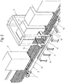
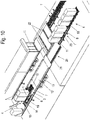
- a device according to the invention is shown, with a stationary transport track 1 and a conveyor track 2, which is displaceable in the longitudinal direction relative to the transport track 1, the conveyor track 2, depending on the requirements under the transport track 1 is at least partially displaceable.
- the stationary transport track 1 like the conveyor track 2, are designed as a roller belt with rollers 10 and the transport track 1 is held stationary on feet 14.
- a transfer device 3 designed as a portal is arranged, which can be displaced in the longitudinal direction along rails 6, specifically for removing transport containers 11 from the conveyor track 1 and placing them on the conveyor track 2, so that the rails 6, on which the converter 3 is guided, can be displaced both in the assigned end region of the transport path 1 and in a region of the conveyor path 2.
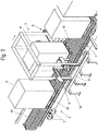
- the converter 3 has two opposing clamping elements 5 which can be clamped against one another and which grips the transport container 10 to be moved and lifts it off the transport track 1, moves it over the longitudinal rails 6 to the area of the conveyor track 2 and sets it down there. This is particularly evident in the Figures 2 and 3 to recognize the Figure 2 the transfer device 3 reproduces in a position in which the transport container 11, which is otherwise designed as a pallet 18 on the underside, is lifted from the transport path 1.
- the clamping elements 5 can be moved vertically for raising and lowering the transport container 11. Instead of such clamping elements 5, gripping elements can also be provided, alternatively also lifting forks which reach under the transport container.
- the reciprocating movement of the converter 3 is indicated by arrows in the Figures 2 and 3 indicated.
- a lifting device 4 is provided, which can be moved both transversely and longitudinally and has the fork prongs 9 of a fork which can be moved into a pallet 18.
- the lifting element 4 is held on a pivot bearing 17 and above it can be pivoted through 180 ° in a horizontal plane.
- the lifting element 4 is rotatably attached to a push frame 16, which in turn has cross rails 15 on which the lifting element 4 can be displaced transversely to the loading surface 12.
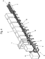
- the push frame 16 can be displaced into the conveyor track 2, as shown in FIG Figure 6 can be seen.
- rollers 7 are attached, by means of which the conveyor track 2 can be moved in the longitudinal direction.
- Laterally connected dampers 8 rest on the side walls 13 of the loading area 12 and allow lateral evasion or a lateral correction of the position of the conveyor track 2 if the loading area 12 is not exactly aligned.
- the broadside of the transport containers 11 is arranged transversely to the longitudinal extent of the loading surface 12, so that the transport containers 11, offset by 90 °, on the transport containers 11 arranged relative to the conveyor track 2 have to be rotated accordingly.
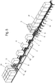
- FIG. 8 clearly recognizable turntable 19 is provided, which is also provided with rollers 10, which are aligned for the transfer of the respective transport container 11 from the conveyor track 2 to the turntable 19.
- the rollers 10 are brought into a position in which the turntable 19 is rotated by 90 °, so that the broad side of the transport container 11 is aligned like that already on the loading surface 12.
- the turntable 19 is pivoted through 90 ° until the rollers 10 of both the conveyor track 2 and the turntable 19 run in the same direction.
- the control of the entire loading or unloading process i.e. at which position on the loading area 12 the transport containers 11 are to be deposited or removed, can be computer-assisted, possibly also via sensors in the event that the loading area 12 is only to be additionally equipped.
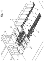
- the stationary transport track 1 and the conveyor track 2 are arranged in a common horizontal plane. Between the two, a movable intermediate track 1 'is provided in the same horizontal plane, so to speak, as a feeder from the stationary transport track 1 to the conveyor track 2, with lateral dampers 8, comparable to those on the conveyor track 2 and with rollers 7.
- the conveyor track 2 is positioned on a slide 20 which is provided on the opposite longitudinal sides with guide rails 21 on which the dampers 8 rest.
- Each of the intermediate tracks 1 ' is guided for lateral guidance along two parallel and spaced guide bars 23, which are also stationary, with the rollers 7 resting on the mutually facing sides of the guide bars 23 for guiding the intermediate track 1'.
- the intermediate track 1 is also driven.
- FIG. 11 a position of the conveyor track 2 is shown in which this is moved from the left-hand loading area 12, which is fully equipped with transport containers 11, into the area of the right loading area 12 in order to load this loading area 12 with transport containers 11 that are on the stationary transport track 1 and the adjoining intermediate track 1 'are available.
- the carriage 20, on which the conveyor track 2 together with the turntable 19 and the lifting device 4 is located, is along guide rails 22 which extend in a stationary manner transversely to the conveying direction of the conveyor track 2 so that the conveyor track 2 and the intermediate track 1 'in their loading position can be brought.
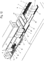
- the Figure 12 shows a situation in which the intermediate track 1 ′, equipped with transport containers 11, has partially driven over the slide 20, just like the loading area 12, but has not yet reached the conveyor track 2.
- a transport container 11 is placed on the turntable 19 so that the forks of the lifting device 4 can move under the pallet 18, lift it and pivot it by 180 ° in the horizontal plane, the lifting device 4 together with the transport container 11 being moved by means of the push frame 16 in such a way that the transport container 11 is aligned with the gap into which the transport container 11 is to be deposited. This takes place in that, as described above, the push frame 16 moves in the conveying direction of the conveyor track 2 after pivoting.
Landscapes
- Engineering & Computer Science (AREA)
- Aviation & Aerospace Engineering (AREA)
- Mechanical Engineering (AREA)
- Loading Or Unloading Of Vehicles (AREA)
- Warehouses Or Storage Devices (AREA)
- Intermediate Stations On Conveyors (AREA)
Applications Claiming Priority (1)
| Application Number | Priority Date | Filing Date | Title |
|---|---|---|---|
| DE102020105056 | 2020-02-26 |
Publications (3)
| Publication Number | Publication Date |
|---|---|
| EP3872012A1 true EP3872012A1 (fr) | 2021-09-01 |
| EP3872012C0 EP3872012C0 (fr) | 2024-04-03 |
| EP3872012B1 EP3872012B1 (fr) | 2024-04-03 |
Family
ID=74732608
Family Applications (1)
| Application Number | Title | Priority Date | Filing Date |
|---|---|---|---|
| EP21158705.0A Active EP3872012B1 (fr) | 2020-02-26 | 2021-02-23 | Dispositif de chargement et de déchargement d'un véhicule utilitaire comprenant une zone de chargement |
Country Status (2)
| Country | Link |
|---|---|
| EP (1) | EP3872012B1 (fr) |
| DE (1) | DE102021104231A1 (fr) |
Citations (8)
| Publication number | Priority date | Publication date | Assignee | Title |
|---|---|---|---|---|
| DE3151402A1 (de) * | 1981-12-24 | 1983-07-14 | Mannesmann AG, 4000 Düsseldorf | Vorrichtung zum be- und entladen eines fahrzeuges |
| DE19935072A1 (de) | 1999-07-28 | 2001-02-01 | Mannesmann Vdo Ag | Verfahren zum Verladen einer Ladung und Verladevorrichtung zur Anwendung bei dem Verfahren |
| US20040033126A1 (en) * | 2002-08-15 | 2004-02-19 | Lars Thogersen | Apparatus for loading and unloading a cargo compartment of an aircraft |
| EP1759990A2 (fr) * | 2002-03-11 | 2007-03-07 | Telair International AB | Système de chargement et de déchargement de marchandises de détail dans un espace de chargement, en particulier d'une cale d'avion, et système de transport intermédiaire ou unité de transport correspondante. |
| WO2014174005A1 (fr) * | 2013-04-26 | 2014-10-30 | J. Schmalz Gmbh | Système transporteur pour le chargement ou le déchargement de marchandises individualisables |
| CN104176517A (zh) * | 2014-08-11 | 2014-12-03 | 中国人民解放军总后勤部建筑工程研究所 | 一种棚车装卸机 |
| CN107934595A (zh) | 2017-12-14 | 2018-04-20 | 雅化集团三台化工有限公司 | 一种单向上料型机器人装车系统 |
| WO2019178260A1 (fr) | 2018-03-13 | 2019-09-19 | Fast Global Solutions, Inc. | Déchargeur à portique |
-
2021
- 2021-02-23 EP EP21158705.0A patent/EP3872012B1/fr active Active
- 2021-02-23 DE DE102021104231.3A patent/DE102021104231A1/de not_active Withdrawn
Patent Citations (8)
| Publication number | Priority date | Publication date | Assignee | Title |
|---|---|---|---|---|
| DE3151402A1 (de) * | 1981-12-24 | 1983-07-14 | Mannesmann AG, 4000 Düsseldorf | Vorrichtung zum be- und entladen eines fahrzeuges |
| DE19935072A1 (de) | 1999-07-28 | 2001-02-01 | Mannesmann Vdo Ag | Verfahren zum Verladen einer Ladung und Verladevorrichtung zur Anwendung bei dem Verfahren |
| EP1759990A2 (fr) * | 2002-03-11 | 2007-03-07 | Telair International AB | Système de chargement et de déchargement de marchandises de détail dans un espace de chargement, en particulier d'une cale d'avion, et système de transport intermédiaire ou unité de transport correspondante. |
| US20040033126A1 (en) * | 2002-08-15 | 2004-02-19 | Lars Thogersen | Apparatus for loading and unloading a cargo compartment of an aircraft |
| WO2014174005A1 (fr) * | 2013-04-26 | 2014-10-30 | J. Schmalz Gmbh | Système transporteur pour le chargement ou le déchargement de marchandises individualisables |
| CN104176517A (zh) * | 2014-08-11 | 2014-12-03 | 中国人民解放军总后勤部建筑工程研究所 | 一种棚车装卸机 |
| CN107934595A (zh) | 2017-12-14 | 2018-04-20 | 雅化集团三台化工有限公司 | 一种单向上料型机器人装车系统 |
| WO2019178260A1 (fr) | 2018-03-13 | 2019-09-19 | Fast Global Solutions, Inc. | Déchargeur à portique |
Also Published As
| Publication number | Publication date |
|---|---|
| DE102021104231A1 (de) | 2021-08-26 |
| EP3872012C0 (fr) | 2024-04-03 |
| EP3872012B1 (fr) | 2024-04-03 |
Similar Documents
| Publication | Publication Date | Title |
|---|---|---|
| EP2885199B1 (fr) | Remorque de train de remorques | |
| EP1908711B1 (fr) | Dispositif de levage d'une couche constituée d'une multitude de récipients ou analogues | |
| EP2332865B9 (fr) | Dispositif de palettisation et/ou de dépalettisation | |
| EP2648997B1 (fr) | Moyen de réception de charge universel pour la manutention sans palette de produits à emmagasiner | |
| EP2128047B2 (fr) | Dispositif de réception pour un véhicule transporteur | |
| DE9418354U1 (de) | Lastklemmvorrichtung mit erweitertem vertikalem Bewegungsbereich | |
| DE202014006562U1 (de) | Fördereinheit und Fördersystem zum Fördern von Ladungsträgern | |
| DE102017102930B4 (de) | Hebevorrichtung und Anlage zum Transportieren von Stückgut | |
| WO2013044895A1 (fr) | Dispositif de déplacement d'unités de transport | |
| EP3214026A1 (fr) | Dispositif de déplacement de porteurs de charge | |
| DE3316050A1 (de) | Einrichtung zum transport von werkstueckpaletten | |
| DE19503198C1 (de) | Vorrichtung für das seitliche Be- und Entladen von Fahrzeugen | |
| DE8706291U1 (de) | Entlade- und ggf. Beladevorrichtung | |
| DE102013019688A1 (de) | Transportsystem mit Fahrzeug, insbesondere zum Transportieren eines Lastaufnahmemittels | |
| DE102017104751B4 (de) | Transportvorrichtung | |
| DE2802345A1 (de) | Vorrichtung zum umschlagen von ladeeinheiten | |
| EP2261129B1 (fr) | Palette de transport d'objets à l'aide d'une empileuse | |
| DE3437127A1 (de) | Fertigungsdurchlaufsystem | |
| EP3872012B1 (fr) | Dispositif de chargement et de déchargement d'un véhicule utilitaire comprenant une zone de chargement | |
| DE19607563C1 (de) | Handhabungseinrichtung, insbesondere Palettenumsetzeinrichtung | |
| EP0083751B1 (fr) | Dispositif pour le transport de profilés et de barres | |
| DE4331605C2 (de) | Transportfahrzeug für auf Paletten aufgestapeltes bogenförmiges Material | |
| DE19719567A1 (de) | Vorrichtung zum Be- und Entladen von Lastkraftwagen mit Paletten | |
| DE2502302B2 (de) | Transportvorrichtung für Paletten | |
| DE2719727A1 (de) | Gabelstapelgeraet |
Legal Events
| Date | Code | Title | Description |
|---|---|---|---|
| PUAI | Public reference made under article 153(3) epc to a published international application that has entered the european phase |
Free format text: ORIGINAL CODE: 0009012 |
|
| STAA | Information on the status of an ep patent application or granted ep patent |
Free format text: STATUS: THE APPLICATION HAS BEEN PUBLISHED |
|
| AK | Designated contracting states |
Kind code of ref document: A1 Designated state(s): AL AT BE BG CH CY CZ DE DK EE ES FI FR GB GR HR HU IE IS IT LI LT LU LV MC MK MT NL NO PL PT RO RS SE SI SK SM TR |
|
| STAA | Information on the status of an ep patent application or granted ep patent |
Free format text: STATUS: REQUEST FOR EXAMINATION WAS MADE |
|
| 17P | Request for examination filed |
Effective date: 20211025 |
|
| RBV | Designated contracting states (corrected) |
Designated state(s): AL AT BE BG CH CY CZ DE DK EE ES FI FR GB GR HR HU IE IS IT LI LT LU LV MC MK MT NL NO PL PT RO RS SE SI SK SM TR |
|
| GRAP | Despatch of communication of intention to grant a patent |
Free format text: ORIGINAL CODE: EPIDOSNIGR1 |
|
| STAA | Information on the status of an ep patent application or granted ep patent |
Free format text: STATUS: GRANT OF PATENT IS INTENDED |
|
| INTG | Intention to grant announced |
Effective date: 20231214 |
|
| GRAS | Grant fee paid |
Free format text: ORIGINAL CODE: EPIDOSNIGR3 |
|
| GRAA | (expected) grant |
Free format text: ORIGINAL CODE: 0009210 |
|
| STAA | Information on the status of an ep patent application or granted ep patent |
Free format text: STATUS: THE PATENT HAS BEEN GRANTED |
|
| RAP3 | Party data changed (applicant data changed or rights of an application transferred) |
Owner name: SCHIER, TAMARA Owner name: SCHIER, JAN LUCA Owner name: SCHIER, ALEXANDER Owner name: KOLLIWAVER GMBH |
|
| AK | Designated contracting states |
Kind code of ref document: B1 Designated state(s): AL AT BE BG CH CY CZ DE DK EE ES FI FR GB GR HR HU IE IS IT LI LT LU LV MC MK MT NL NO PL PT RO RS SE SI SK SM TR |
|
| REG | Reference to a national code |
Ref country code: CH Ref legal event code: EP |
|
| REG | Reference to a national code |
Ref country code: IE Ref legal event code: FG4D Free format text: LANGUAGE OF EP DOCUMENT: GERMAN |
|
| REG | Reference to a national code |
Ref country code: DE Ref legal event code: R096 Ref document number: 502021003152 Country of ref document: DE |
|
| U01 | Request for unitary effect filed |
Effective date: 20240416 |
|
| U07 | Unitary effect registered |
Designated state(s): AT BE BG DE DK EE FI FR IT LT LU LV MT NL PT SE SI Effective date: 20240423 |
|
| PG25 | Lapsed in a contracting state [announced via postgrant information from national office to epo] |
Ref country code: IS Free format text: LAPSE BECAUSE OF FAILURE TO SUBMIT A TRANSLATION OF THE DESCRIPTION OR TO PAY THE FEE WITHIN THE PRESCRIBED TIME-LIMIT Effective date: 20240803 |
|
| PG25 | Lapsed in a contracting state [announced via postgrant information from national office to epo] |
Ref country code: HR Free format text: LAPSE BECAUSE OF FAILURE TO SUBMIT A TRANSLATION OF THE DESCRIPTION OR TO PAY THE FEE WITHIN THE PRESCRIBED TIME-LIMIT Effective date: 20240403 |
|
| PG25 | Lapsed in a contracting state [announced via postgrant information from national office to epo] |
Ref country code: GR Free format text: LAPSE BECAUSE OF FAILURE TO SUBMIT A TRANSLATION OF THE DESCRIPTION OR TO PAY THE FEE WITHIN THE PRESCRIBED TIME-LIMIT Effective date: 20240704 |
|
| PG25 | Lapsed in a contracting state [announced via postgrant information from national office to epo] |
Ref country code: ES Free format text: LAPSE BECAUSE OF FAILURE TO SUBMIT A TRANSLATION OF THE DESCRIPTION OR TO PAY THE FEE WITHIN THE PRESCRIBED TIME-LIMIT Effective date: 20240403 |
|
| PG25 | Lapsed in a contracting state [announced via postgrant information from national office to epo] |
Ref country code: CZ Free format text: LAPSE BECAUSE OF FAILURE TO SUBMIT A TRANSLATION OF THE DESCRIPTION OR TO PAY THE FEE WITHIN THE PRESCRIBED TIME-LIMIT Effective date: 20240403 |
|
| PG25 | Lapsed in a contracting state [announced via postgrant information from national office to epo] |
Ref country code: PL Free format text: LAPSE BECAUSE OF FAILURE TO SUBMIT A TRANSLATION OF THE DESCRIPTION OR TO PAY THE FEE WITHIN THE PRESCRIBED TIME-LIMIT Effective date: 20240403 |
|
| PG25 | Lapsed in a contracting state [announced via postgrant information from national office to epo] |
Ref country code: PL Free format text: LAPSE BECAUSE OF FAILURE TO SUBMIT A TRANSLATION OF THE DESCRIPTION OR TO PAY THE FEE WITHIN THE PRESCRIBED TIME-LIMIT Effective date: 20240403 Ref country code: NO Free format text: LAPSE BECAUSE OF FAILURE TO SUBMIT A TRANSLATION OF THE DESCRIPTION OR TO PAY THE FEE WITHIN THE PRESCRIBED TIME-LIMIT Effective date: 20240703 Ref country code: IS Free format text: LAPSE BECAUSE OF FAILURE TO SUBMIT A TRANSLATION OF THE DESCRIPTION OR TO PAY THE FEE WITHIN THE PRESCRIBED TIME-LIMIT Effective date: 20240803 Ref country code: HR Free format text: LAPSE BECAUSE OF FAILURE TO SUBMIT A TRANSLATION OF THE DESCRIPTION OR TO PAY THE FEE WITHIN THE PRESCRIBED TIME-LIMIT Effective date: 20240403 Ref country code: GR Free format text: LAPSE BECAUSE OF FAILURE TO SUBMIT A TRANSLATION OF THE DESCRIPTION OR TO PAY THE FEE WITHIN THE PRESCRIBED TIME-LIMIT Effective date: 20240704 Ref country code: ES Free format text: LAPSE BECAUSE OF FAILURE TO SUBMIT A TRANSLATION OF THE DESCRIPTION OR TO PAY THE FEE WITHIN THE PRESCRIBED TIME-LIMIT Effective date: 20240403 Ref country code: CZ Free format text: LAPSE BECAUSE OF FAILURE TO SUBMIT A TRANSLATION OF THE DESCRIPTION OR TO PAY THE FEE WITHIN THE PRESCRIBED TIME-LIMIT Effective date: 20240403 Ref country code: RS Free format text: LAPSE BECAUSE OF FAILURE TO SUBMIT A TRANSLATION OF THE DESCRIPTION OR TO PAY THE FEE WITHIN THE PRESCRIBED TIME-LIMIT Effective date: 20240703 |
|
| REG | Reference to a national code |
Ref country code: DE Ref legal event code: R097 Ref document number: 502021003152 Country of ref document: DE |
|
| PG25 | Lapsed in a contracting state [announced via postgrant information from national office to epo] |
Ref country code: SK Free format text: LAPSE BECAUSE OF FAILURE TO SUBMIT A TRANSLATION OF THE DESCRIPTION OR TO PAY THE FEE WITHIN THE PRESCRIBED TIME-LIMIT Effective date: 20240403 Ref country code: RO Free format text: LAPSE BECAUSE OF FAILURE TO SUBMIT A TRANSLATION OF THE DESCRIPTION OR TO PAY THE FEE WITHIN THE PRESCRIBED TIME-LIMIT Effective date: 20240403 |
|
| PG25 | Lapsed in a contracting state [announced via postgrant information from national office to epo] |
Ref country code: SM Free format text: LAPSE BECAUSE OF FAILURE TO SUBMIT A TRANSLATION OF THE DESCRIPTION OR TO PAY THE FEE WITHIN THE PRESCRIBED TIME-LIMIT Effective date: 20240403 |
|
| PG25 | Lapsed in a contracting state [announced via postgrant information from national office to epo] |
Ref country code: SM Free format text: LAPSE BECAUSE OF FAILURE TO SUBMIT A TRANSLATION OF THE DESCRIPTION OR TO PAY THE FEE WITHIN THE PRESCRIBED TIME-LIMIT Effective date: 20240403 Ref country code: SK Free format text: LAPSE BECAUSE OF FAILURE TO SUBMIT A TRANSLATION OF THE DESCRIPTION OR TO PAY THE FEE WITHIN THE PRESCRIBED TIME-LIMIT Effective date: 20240403 Ref country code: RO Free format text: LAPSE BECAUSE OF FAILURE TO SUBMIT A TRANSLATION OF THE DESCRIPTION OR TO PAY THE FEE WITHIN THE PRESCRIBED TIME-LIMIT Effective date: 20240403 |
|
| PLBE | No opposition filed within time limit |
Free format text: ORIGINAL CODE: 0009261 |
|
| STAA | Information on the status of an ep patent application or granted ep patent |
Free format text: STATUS: NO OPPOSITION FILED WITHIN TIME LIMIT |
|
| 26N | No opposition filed |
Effective date: 20250106 |
|
| U21 | Renewal fee for the european patent with unitary effect paid with additional fee |
Year of fee payment: 5 Effective date: 20250318 |
|
| PG25 | Lapsed in a contracting state [announced via postgrant information from national office to epo] |
Ref country code: MC Free format text: LAPSE BECAUSE OF FAILURE TO SUBMIT A TRANSLATION OF THE DESCRIPTION OR TO PAY THE FEE WITHIN THE PRESCRIBED TIME-LIMIT Effective date: 20240403 |
|
| REG | Reference to a national code |
Ref country code: CH Ref legal event code: PL |
|
| PG25 | Lapsed in a contracting state [announced via postgrant information from national office to epo] |
Ref country code: CH Free format text: LAPSE BECAUSE OF NON-PAYMENT OF DUE FEES Effective date: 20250228 |
|
| GBPC | Gb: european patent ceased through non-payment of renewal fee |
Effective date: 20250223 |
|
| PG25 | Lapsed in a contracting state [announced via postgrant information from national office to epo] |
Ref country code: GB Free format text: LAPSE BECAUSE OF NON-PAYMENT OF DUE FEES Effective date: 20250223 |
|
| PG25 | Lapsed in a contracting state [announced via postgrant information from national office to epo] |
Ref country code: IE Free format text: LAPSE BECAUSE OF NON-PAYMENT OF DUE FEES Effective date: 20250223 |