EP3872012A1 - Loading and unloading device for a commercial vehicle comprising a loading platform - Google Patents
Loading and unloading device for a commercial vehicle comprising a loading platform Download PDFInfo
- Publication number
- EP3872012A1 EP3872012A1 EP21158705.0A EP21158705A EP3872012A1 EP 3872012 A1 EP3872012 A1 EP 3872012A1 EP 21158705 A EP21158705 A EP 21158705A EP 3872012 A1 EP3872012 A1 EP 3872012A1
- Authority
- EP
- European Patent Office
- Prior art keywords
- track
- conveyor track
- transport
- loading
- conveyor
- Prior art date
- Legal status (The legal status is an assumption and is not a legal conclusion. Google has not performed a legal analysis and makes no representation as to the accuracy of the status listed.)
- Granted
Links
- 238000012546 transfer Methods 0.000 description 5
- 238000013016 damping Methods 0.000 description 2
- 238000013461 design Methods 0.000 description 2
- 238000006073 displacement reaction Methods 0.000 description 2
- 238000012937 correction Methods 0.000 description 1
- 238000011161 development Methods 0.000 description 1
- 230000018109 developmental process Effects 0.000 description 1
- 230000000694 effects Effects 0.000 description 1
- 238000000034 method Methods 0.000 description 1
- 230000000284 resting effect Effects 0.000 description 1
Images


Classifications
-
- B—PERFORMING OPERATIONS; TRANSPORTING
- B65—CONVEYING; PACKING; STORING; HANDLING THIN OR FILAMENTARY MATERIAL
- B65G—TRANSPORT OR STORAGE DEVICES, e.g. CONVEYORS FOR LOADING OR TIPPING, SHOP CONVEYOR SYSTEMS OR PNEUMATIC TUBE CONVEYORS
- B65G67/00—Loading or unloading vehicles
- B65G67/02—Loading or unloading land vehicles
- B65G67/04—Loading land vehicles
- B65G67/08—Loading land vehicles using endless conveyors
Definitions
- lifting devices such as forklifts, pallet trucks or the like have so far been used, which are person-guided and with which transport containers, such as outer boxes, boxes or the like held on transport pallets, can be brought to or from the loading area of a commercial vehicle should be removed.
- the positioning of the transport containers on the loading area of the commercial vehicle is only possible with a considerable amount of work, especially if the loading area only needs to be partially occupied or is already partially occupied in order to then place further transport containers on the loading area.
- the invention is based on the object of further developing a device of the generic type in such a way that a largely automated loading and unloading of the utility vehicle is possible.
- Such a device now enables loading and unloading, as it were, without any significant personalized activity, with the device being able to be controlled via sensors and / or via input into a computer.
- the device has a movable conveyor track, in one end region of which a sliding frame is held which can be moved in the longitudinal direction relative thereto and carries a lifting device which can be moved transversely to the longitudinal extension of the conveyor track, this lifting device being pivotable in the horizontal plane, so that the respective transport container can be placed on the loading area.
- the lifting device can be provided with fork prongs which reach under and lift the transport pallet in a manner known per se.
- the transport container By pivoting in a horizontal plane, the transport container is brought from a position on the conveyor track to the loading area and lowered there.
- a corresponding swivel device for example in the form of a turntable, is also provided between the conveyor track and the lifting device.
- the lifting device can be moved relatively both in the longitudinal direction of the conveyor track and also transversely thereto.
- the push frame, on which the lifting device is held transversely movable is mounted longitudinally displaceably in the conveyor track, for which purpose longitudinal spars of the push frame are guided in longitudinal guides of the conveyor track.
- the push frame has rails at its free end, on which the lifting device can be driven along with it.
- the push frame can also be driven, preferably computer-controlled, as are all movements of the lifting device and a driven movement of the conveyor track in the longitudinal direction.
- damping members are provided which, when in function, rest against the opposite side walls of the loading area, so that the conveyor track can be aligned to a small extent if the loading area is not exactly aligned with the conveyor track.
- a stationary transport path is provided via which transport containers, in particular those which have a transport pallet as a substructure, are fed to the conveyor path.
- the travel length of the conveyor track depends on the space available on the loading area. This means that if the transport containers have already been placed on the loading area, the conveyor track is only moved so far that the transport containers to be loaded directly adjoin the existing ones.
- an intermediate track which can be moved in the transport direction via its own drive and which is taken over from the fixed transport track can be provided between the fixed transport track and the conveyor track Transport container transported to the conveyor track, this intermediate track is rail-guided outside the loading area and in the area of the loading area by means of damping members, which are guided against lateral surfaces of the loading area.
- the intermediate track thus functions as a feeder, so to speak.
- the device according to claim 1 is displaced transversely to the longitudinal extension of the conveyor track.
- the rails by means of which the intermediate track is guided to the loading area, are shifted.
- These rails are held on a carriage which can be moved along a second pair of rails from the loading area of one to the loading area of the other loading area, taking the device according to the invention with it.
- Each loading area is assigned a fixed and an intermediate track, while the device with the conveyor track and the lifting device is used to equip the several loading areas.
- a further variant of the invention provides that, dispensing with the intermediate track, the conveyor track with connected pusher frame and lifting device can be displaced at least in some areas under the stationary transport track.
- the transport containers located on the transport track must be converted, for which a converter is provided which has clamping or gripping elements with which the respective transport container of the transport track can be converted to the conveyor track.
- gripping or clamping elements can be moved vertically in order to compensate for the difference in level between the transport track and the conveyor track.
- the converter can also be displaced in the longitudinal direction, preferably guided on rails, in order to get from the overlap area with the transport track into the overlap area of the conveyor track.
- Both the transport track and the conveyor track are preferably designed as roller tracks, with at least some of the rollers being driven. However, it is also conceivable to design both tracks or one each as a chain conveyor. The design of the transport track and the conveyor track are to be selected depending on the requirements.
- the drive of the conveyor track for its longitudinal displacement takes place by a motor, preferably an electric motor, the conveyor track being supported on the ground by means of rollers, as is the intermediate track.
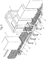
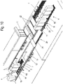
- a device according to the invention is shown, with a stationary transport track 1 and a conveyor track 2, which is displaceable in the longitudinal direction relative to the transport track 1, the conveyor track 2, depending on the requirements under the transport track 1 is at least partially displaceable.
- the stationary transport track 1 like the conveyor track 2, are designed as a roller belt with rollers 10 and the transport track 1 is held stationary on feet 14.
- a transfer device 3 designed as a portal is arranged, which can be displaced in the longitudinal direction along rails 6, specifically for removing transport containers 11 from the conveyor track 1 and placing them on the conveyor track 2, so that the rails 6, on which the converter 3 is guided, can be displaced both in the assigned end region of the transport path 1 and in a region of the conveyor path 2.
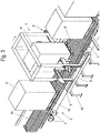
- the converter 3 has two opposing clamping elements 5 which can be clamped against one another and which grips the transport container 10 to be moved and lifts it off the transport track 1, moves it over the longitudinal rails 6 to the area of the conveyor track 2 and sets it down there. This is particularly evident in the Figures 2 and 3 to recognize the Figure 2 the transfer device 3 reproduces in a position in which the transport container 11, which is otherwise designed as a pallet 18 on the underside, is lifted from the transport path 1.
- the clamping elements 5 can be moved vertically for raising and lowering the transport container 11. Instead of such clamping elements 5, gripping elements can also be provided, alternatively also lifting forks which reach under the transport container.
- the reciprocating movement of the converter 3 is indicated by arrows in the Figures 2 and 3 indicated.
- a lifting device 4 is provided, which can be moved both transversely and longitudinally and has the fork prongs 9 of a fork which can be moved into a pallet 18.
- the lifting element 4 is held on a pivot bearing 17 and above it can be pivoted through 180 ° in a horizontal plane.
- the lifting element 4 is rotatably attached to a push frame 16, which in turn has cross rails 15 on which the lifting element 4 can be displaced transversely to the loading surface 12.
- the push frame 16 can be displaced into the conveyor track 2, as shown in FIG Figure 6 can be seen.
- rollers 7 are attached, by means of which the conveyor track 2 can be moved in the longitudinal direction.
- Laterally connected dampers 8 rest on the side walls 13 of the loading area 12 and allow lateral evasion or a lateral correction of the position of the conveyor track 2 if the loading area 12 is not exactly aligned.
- the broadside of the transport containers 11 is arranged transversely to the longitudinal extent of the loading surface 12, so that the transport containers 11, offset by 90 °, on the transport containers 11 arranged relative to the conveyor track 2 have to be rotated accordingly.
- FIG. 8 clearly recognizable turntable 19 is provided, which is also provided with rollers 10, which are aligned for the transfer of the respective transport container 11 from the conveyor track 2 to the turntable 19.
- the rollers 10 are brought into a position in which the turntable 19 is rotated by 90 °, so that the broad side of the transport container 11 is aligned like that already on the loading surface 12.
- the turntable 19 is pivoted through 90 ° until the rollers 10 of both the conveyor track 2 and the turntable 19 run in the same direction.
- the control of the entire loading or unloading process i.e. at which position on the loading area 12 the transport containers 11 are to be deposited or removed, can be computer-assisted, possibly also via sensors in the event that the loading area 12 is only to be additionally equipped.
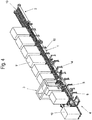
- the stationary transport track 1 and the conveyor track 2 are arranged in a common horizontal plane. Between the two, a movable intermediate track 1 'is provided in the same horizontal plane, so to speak, as a feeder from the stationary transport track 1 to the conveyor track 2, with lateral dampers 8, comparable to those on the conveyor track 2 and with rollers 7.
- the conveyor track 2 is positioned on a slide 20 which is provided on the opposite longitudinal sides with guide rails 21 on which the dampers 8 rest.
- Each of the intermediate tracks 1 ' is guided for lateral guidance along two parallel and spaced guide bars 23, which are also stationary, with the rollers 7 resting on the mutually facing sides of the guide bars 23 for guiding the intermediate track 1'.
- the intermediate track 1 is also driven.
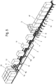
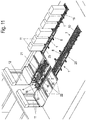
- FIG. 11 a position of the conveyor track 2 is shown in which this is moved from the left-hand loading area 12, which is fully equipped with transport containers 11, into the area of the right loading area 12 in order to load this loading area 12 with transport containers 11 that are on the stationary transport track 1 and the adjoining intermediate track 1 'are available.
- the carriage 20, on which the conveyor track 2 together with the turntable 19 and the lifting device 4 is located, is along guide rails 22 which extend in a stationary manner transversely to the conveying direction of the conveyor track 2 so that the conveyor track 2 and the intermediate track 1 'in their loading position can be brought.
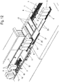
- the Figure 12 shows a situation in which the intermediate track 1 ′, equipped with transport containers 11, has partially driven over the slide 20, just like the loading area 12, but has not yet reached the conveyor track 2.
- a transport container 11 is placed on the turntable 19 so that the forks of the lifting device 4 can move under the pallet 18, lift it and pivot it by 180 ° in the horizontal plane, the lifting device 4 together with the transport container 11 being moved by means of the push frame 16 in such a way that the transport container 11 is aligned with the gap into which the transport container 11 is to be deposited. This takes place in that, as described above, the push frame 16 moves in the conveying direction of the conveyor track 2 after pivoting.
Abstract
Eine Einrichtung zum Be- und Entladen eines eine Ladefläche (12) aufweisenden Nutzfahrzeuges oder eines Containers, ausgebildet durch eine verfahrbare Förderbahn (2), in deren einem Endbereich ein in Längsrichtung relativ dazu bewegbares Schubgestell (16) gehalten ist, das eine, in horizontaler Ebene verschwenkbare Hubeinrichtung (4) trägt, die quer zur Längserstreckung der Förderbahn (2) bewegbar ist.A device for loading and unloading a utility vehicle or a container with a loading area (12), formed by a movable conveyor track (2), in one end region of which a longitudinally movable sliding frame (16) is held Carrying plane pivotable lifting device (4) which can be moved transversely to the longitudinal extension of the conveyor track (2).
Description
Zum Be- und Entladen eines Nutzfahrzeuges oder eines Containers kommen bislang Hubgeräte, wie Gabelstapler, Hubwagen oder dergleichen zum Einsatz, die personengeführt sind und mit denen jeweils Transportbehälter, wie auf Transportpaletten gehaltene Umkartons, Boxen oder dergleichen auf die Ladefläche eines Nutzfahrzeuges bringbar sind oder davon entnommen werden soll.For loading and unloading a commercial vehicle or a container, lifting devices such as forklifts, pallet trucks or the like have so far been used, which are person-guided and with which transport containers, such as outer boxes, boxes or the like held on transport pallets, can be brought to or from the loading area of a commercial vehicle should be removed.
Insbesondere dann, wenn Gefriergut be- oder entladen werden soll, ergeben sich hinsichtlich der körperlichen Belastung der das Hubgerät führenden Person allergrößte Probleme, da diese sich in Kühlräumen mit Temperaturen bewegen muss, die gewährleisten, dass die Kühlkette nicht unterbrochen wird.Particularly when frozen goods are to be loaded or unloaded, the greatest problems arise with regard to the physical strain on the person operating the lifting device, since they must move in cold rooms at temperatures that ensure that the cold chain is not interrupted.
Diese äußerst beschwerlichen Arbeitsbedingungen stellen eine erhebliche gesundheitliche Gefährdung dar.These extremely arduous working conditions pose a significant health risk.
Unabhängig davon, ist auch die Beschickung bzw. Entnahme des Nutzfahrzeuges, d.h. eines Lkws, zeitaufwändig und steht den gestellten Forderungen nach einer rationellen Arbeitsweise entgegen.Regardless of this, the loading and unloading of the commercial vehicle, i.e. a truck, is also time-consuming and goes against the demands made for an efficient way of working.
Zwar ist schon versucht worden, diese Arbeitsabläufe zu automatisieren, jedoch sind bislang keine Einrichtungen bekannt, die in zufriedenstellender Weise einsatzfähig wären.Attempts have already been made to automate these workflows, but so far no devices are known that would be usable in a satisfactory manner.
Hierzu zählt insbesondere, dass die beispielsweise Beladung des Nutzfahrzeuges mit vereinzelten Transportbehältern nicht vorgesehen ist. Vielmehr wird immer eine gleiche vorgegebene Anzahl von Transportbehältern, die auf Transportbahnen verschieblich gelagert sind, bewegt.This includes in particular that, for example, the loading of the commercial vehicle with isolated transport containers is not provided. Rather, the same predetermined number of transport containers, which are mounted displaceably on transport tracks, is always moved.
Darüber hinaus ist die Positionierung der Transportbehälter auf der Ladefläche des Nutzfahrzeuges nur mit einem erheblichen Arbeitsaufwand möglich, insbesondere dann, wenn die Ladefläche lediglich teilbelegt werden muss oder bereits teilbelegt ist, um anschließend weitere Transportbehälter auf der Ladefläche zu platzieren.In addition, the positioning of the transport containers on the loading area of the commercial vehicle is only possible with a considerable amount of work, especially if the loading area only needs to be partially occupied or is already partially occupied in order to then place further transport containers on the loading area.
Alles in allem stehen die bisherigen Möglichkeiten des Be- und Entladens eines Nutzfahrzeuges den gestellten Anforderungen an ein rationelles Arbeiten entgegen.All in all, the previous options for loading and unloading a commercial vehicle stand in the way of the demands placed on efficient work.
Dies betrifft auch Einrichtungen zum Be- und Entladen eines Nutzfahrzeuges wie sie aus der
Der Erfindung liegt die Aufgabe zugrunde, eine Einrichtung der gattungsgemäßen Art so weiterzuentwickeln, dass eine weitgehend automatisierte Be- und Entladung des Nutzfahrzeuges möglich ist.The invention is based on the object of further developing a device of the generic type in such a way that a largely automated loading and unloading of the utility vehicle is possible.
Diese Aufgabe wird durch eine Einrichtung mit den Merkmalen des Anspruchs 1 gelöst.This object is achieved by a device with the features of
Eine solche Einrichtung ermöglicht nun ein Be- und Entladen quasi ohne wesentliche personalisierte Tätigkeit, wobei die Steuerung der Einrichtung über Sensoren erfolgen kann und/oder über Eingabe in einen Rechner.Such a device now enables loading and unloading, as it were, without any significant personalized activity, with the device being able to be controlled via sensors and / or via input into a computer.
Damit wird erreicht, dass die beschriebenen Belastungen durch die Arbeiten insbesondere in klimatisch ungünstigen Räumen, insbesondere in Kühlräumen oder dergleichen, nun nicht mehr auftreten, was naturgemäß auch zu einer deutlichen Kostenreduzierung beiträgt.This means that the loads described by the work, in particular in climatically unfavorable rooms, in particular in cold storage rooms or the like, no longer occur, which naturally also contributes to a significant reduction in costs.
Gemäß der Erfindung weist die Einrichtung eine verfahrbare Förderbahn auf, in deren einem Endbereich ein in Längsrichtung relativ dazu bewegbares Schubgestell gehalten ist, das eine Hubeinrichtung trägt, die quer zur Längserstreckung der Förderbahn bewegbar ist, wobei diese Hubeinrichtung in horizontaler Ebene verschwenkbar ist, so dass das jeweilige Transportbehältnis auf die Ladefläche setzbar ist.According to the invention, the device has a movable conveyor track, in one end region of which a sliding frame is held which can be moved in the longitudinal direction relative thereto and carries a lifting device which can be moved transversely to the longitudinal extension of the conveyor track, this lifting device being pivotable in the horizontal plane, so that the respective transport container can be placed on the loading area.
Hierzu kann die Hubeinrichtung mit Gabelzinken versehen sein, die in an sich bekannter Weise die Transportpalette untergreifen und anheben. Durch Verschwenken in horizontaler Ebene wird das Transportbehältnis von einer Position auf der Förderbahn hin zur Ladefläche verbracht und dort abgesenkt.For this purpose, the lifting device can be provided with fork prongs which reach under and lift the transport pallet in a manner known per se. By pivoting in a horizontal plane, the transport container is brought from a position on the conveyor track to the loading area and lowered there.
Da die quaderförmigen Transportbehältnisse vielfach eine rechteckige Grundfläche aufweisen, mit unterschiedlich langen Seitenkanten, so dass, je nach Erfordernis, durch die Platzverhältnisse der Ladefläche ein Verdrehen um 90° der Transportbehältnisse in horizontaler Ebene erforderlich ist, ist des Weiteren eine entsprechende Schwenkeinrichtung, beispielsweise in Form eines Drehtellers, zwischen der Förderbahn und der Hubeinrichtung vorgesehen.Since the cuboid transport containers often have a rectangular base area, with side edges of different lengths, so that, depending on the requirement, Due to the space available in the loading area, it is necessary to rotate the transport containers by 90 ° in the horizontal plane, a corresponding swivel device, for example in the form of a turntable, is also provided between the conveyor track and the lifting device.
Zum behinderungsfreien Verschwenken des quaderförmigen Transportbehältnisses ist die Hubeinrichtung sowohl in Längsrichtung der Förderbahn wie auch quer dazu relativ verfahrbar. Hierzu ist das Schubgestell, auf dem die Hubeinrichtung quer beweglich gehalten ist, längs verschieblich in der Förderbahn gelagert, wozu Längsholme des Schubgestells in Längsführungen der Förderbahn geführt sind.For the unobstructed pivoting of the cuboid transport container, the lifting device can be moved relatively both in the longitudinal direction of the conveyor track and also transversely thereto. For this purpose, the push frame, on which the lifting device is held transversely movable, is mounted longitudinally displaceably in the conveyor track, for which purpose longitudinal spars of the push frame are guided in longitudinal guides of the conveyor track.
Zur Querverschiebung der Hubeinrichtung weist das Schubgestell an seinem freien Ende Schienen auf, auf denen entlang die Hubeinrichtung angetrieben bewegbar ist.For the transverse displacement of the lifting device, the push frame has rails at its free end, on which the lifting device can be driven along with it.
Ebenfalls angetrieben bewegbar ist das Schubgestell, vorzugsweise rechnergesteuert ebenso wie sämtliche Bewegungen der Hubeinrichtung und eine angetriebene Bewegung der Förderbahn in Längsrichtung.The push frame can also be driven, preferably computer-controlled, as are all movements of the lifting device and a driven movement of the conveyor track in the longitudinal direction.
An den Außenseiten der Längsführungen der Förderbahn sind Dämpfungsglieder vorgesehen, die in Funktion an den sich gegenüberliegenden Seitenwänden der Ladefläche anliegen, so dass eine Ausrichtung der Förderbahn in einem geringen Maße möglich ist, wenn die Ladefläche nicht exakt mit der Förderbahn fluchtet.On the outer sides of the longitudinal guides of the conveyor track, damping members are provided which, when in function, rest against the opposite side walls of the loading area, so that the conveyor track can be aligned to a small extent if the loading area is not exactly aligned with the conveyor track.
Nach einem weiteren Gedanken der Erfindung ist eine ortsfeste Transportbahn vorgesehen, über die Transportbehälter, insbesondere solche, die als Unterbau eine Transportpalette aufweisen, der Förderbahn zugeführt werden.According to a further concept of the invention, a stationary transport path is provided via which transport containers, in particular those which have a transport pallet as a substructure, are fed to the conveyor path.
Die Verfahrlänge der Förderbahn ist abhängig vom Platzangebot auf der Ladefläche. D.h., bei bereits platzierten Transportbehältern auf der Ladefläche wird die Förderbahn nur so weit verfahren, dass sich die zu beladenden Transportbehälter unmittelbar an die bereits vorhandenen anschließen.The travel length of the conveyor track depends on the space available on the loading area. This means that if the transport containers have already been placed on the loading area, the conveyor track is only moved so far that the transport containers to be loaded directly adjoin the existing ones.
Des Weiteren kann zwischen der ortsfesten Transportbahn und der Förderbahn eine über einen eigenen Antrieb in Transportrichtung verfahrbare Zwischenbahn vorgesehen sein, die von der ortsfesten Transportbahn übernommene Transportbehälter zur Förderbahn transportiert, wobei diese Zwischenbahn außerhalb der Ladefläche schienengeführt ist und im Bereich der Ladefläche mittels Dämpfungsgliedern, die an seitlichen Flächen der Ladefläche anliegend geführt ist. Die Zwischenbahn fungiert somit sozusagen als Zubringer.Furthermore, an intermediate track which can be moved in the transport direction via its own drive and which is taken over from the fixed transport track can be provided between the fixed transport track and the conveyor track Transport container transported to the conveyor track, this intermediate track is rail-guided outside the loading area and in the area of the loading area by means of damping members, which are guided against lateral surfaces of the loading area. The intermediate track thus functions as a feeder, so to speak.
Zur Bestückung mehrerer nebeneinander angeordneter Ladeflächen wird die Einrichtung nach Anspruch 1 quer zur Längserstreckung der Förderbahn verschoben. Hierzu werden die Schienen, mittels der die Zwischenbahn bis zur Ladefläche geführt wird, verschoben. Dabei sind diese Schienen auf einem Schlitten gehalten, der entlang eines zweiten Schienenpaares vom Bestückungsbereich der einen zum Bestückungsbereich der anderen Ladefläche verschoben werden kann, unter Mitnahme der erfindungsgemäßen Einrichtung. Jeder Ladefläche ist eine ortsfeste und eine Zwischenbahn zugeordnet, während die Einrichtung mit der Förderbahn und der Hubeinrichtung zur Bestückung der mehreren Ladeflächen zum Einsatz kommt.In order to equip several loading surfaces arranged next to one another, the device according to
Eine weitere Variante der Erfindung sieht vor, dass unter Verzicht auf die Zwischenbahn die Förderbahn mit angeschlossenem Schubgestell und Hubeinrichtung zumindest bereichsweise unter die ortsfeste Transportbahn verschiebbar ist.A further variant of the invention provides that, dispensing with the intermediate track, the conveyor track with connected pusher frame and lifting device can be displaced at least in some areas under the stationary transport track.
Da die Förderbahn, je nach Verschiebelänge, die Transportbahn unterfährt, also ein anderes Höhenniveau aufweist als die Transportbahn, müssen die auf der Transportbahn befindlichen Transportbehälter umgesetzt werden, wozu ein Umsetzer vorgesehen ist, der Spann- oder Greifelemente aufweist, mit denen der jeweilige Transportbehälter von der Transportbahn zur Förderbahn umgesetzt werden kann.Since the conveyor track, depending on the shifting length, passes under the transport track, i.e. has a different height level than the transport track, the transport containers located on the transport track must be converted, for which a converter is provided which has clamping or gripping elements with which the respective transport container of the transport track can be converted to the conveyor track.
Diese Greif- oder Spannelemente sind vertikal verschiebbar, um die Niveaudifferenz zwischen der Transportbahn und der Förderbahn auszugleichen.These gripping or clamping elements can be moved vertically in order to compensate for the difference in level between the transport track and the conveyor track.
Des Weiteren ist der Umsetzer auch in Längsrichtung verschiebbar, bevorzugt auf Schienen geführt, um vom Überdeckungsbereich mit Transportbahn in den Überdeckungsbereich der Förderbahn zu gelangen.Furthermore, the converter can also be displaced in the longitudinal direction, preferably guided on rails, in order to get from the overlap area with the transport track into the overlap area of the conveyor track.
Bevorzugt sind sowohl die Transportbahn wie auch die Förderbahn als Rollenbahn ausgebildet, wobei zumindest ein Teil der Rollen angetrieben wird. Denkbar ist jedoch auch beide Bahnen oder jeweils eine als Kettenförderer auszubilden. Die Ausgestaltung der Transportbahn und der Förderbahn sind je nach Anforderung auszuwählen. Der Antrieb der Förderbahn zu deren Längsverschiebung erfolgt motorisch, vorzugsweise elektromotorisch, wobei sich die Förderbahn mittels Laufrollen am Untergrund abstützt, ebenso wie die Zwischenbahn.Both the transport track and the conveyor track are preferably designed as roller tracks, with at least some of the rollers being driven. However, it is also conceivable to design both tracks or one each as a chain conveyor. The design of the transport track and the conveyor track are to be selected depending on the requirements. The drive of the conveyor track for its longitudinal displacement takes place by a motor, preferably an electric motor, the conveyor track being supported on the ground by means of rollers, as is the intermediate track.
Weitere vorteilhafte Ausbildungen der Erfindung sind in den Unteransprüchen gekennzeichnet.Further advantageous developments of the invention are characterized in the subclaims.
Ausführungsbeispiele der Erfindung werden nachfolgend anhand der beigefügten Zeichnungen beschrieben.Embodiments of the invention are described below with reference to the accompanying drawings.
- Figuren 1-8Figures 1-8
- ein Ausführungsbeispiel einer erfindungsgemäßen Einrichtung jeweils in unterschiedlichen Funktionsstellungen in perspektivischer Ansichtan embodiment of a device according to the invention each in different functional positions in a perspective view
- Figuren 9-12Figures 9-12
- ein weiteres Ausführungsbeispiel der erfindungsgemäßen Einrichtung, gleichfalls in unterschiedlichen Funktionsstellungen schaubildlich dargestellt.a further embodiment of the device according to the invention, also shown diagrammatically in different functional positions.
In der
Die ortsfeste Transportbahn 1, ebenso wie die Förderbahn 2 sind als Rollenband mit Rollen 10 ausgebildet und die Transportbahn 1 ortsfest auf Füßen 14 gehalten.The
An dem der Förderbahn 2 zugewandten Endbereich der Transportbahn 1 ist ein als Portal ausgebildeter Umsetzer 3 angeordnet, der entlang von Schienen 6 in Längsrichtung verschiebbar ist und zwar zur Entnahme von Transportbehältnissen 11 von der Transportbahn 1 und Absetzen auf der Förderbahn 2, so dass die Schienen 6, auf denen der Umsetzer 3 geführt ist, sowohl in den zugeordneten Endbereich der Transportbahn 1 wie auch in einen Bereich der Förderbahn 2 verschiebbar ist.At the end of the
Der Umsetzer 3 weist zwei sich gegenüberliegende Spannelemente 5 auf, die gegeneinander spannbar sind und das umzusetzende Transportbehältnis 10 derart ergreift und von der Transportbahn 1 abhebt, über die Längsschienen 6 bis in Bereich der Förderbahn 2 verfährt und dort absetzt. Dies ist besonders deutlich in den
In der
Die Spannelemente 5 sind vertikal verfahrbar zum Anheben und Absenken des Transportbehältnisses 11. Anstelle solcher Spannelemente 5 können auch Greifelemente vorgesehen sein, alternativ auch Hubgabeln, die das Transportbehältnis untergreifen. Die Hin- und Herbewegung des Umsetzers 3 ist durch Pfeile in den
Wie weiter in der
In der
Das Hubelement 4 ist an einem Drehlager 17 gehalten und darüber in einer horizontalen Ebene um 180° verschwenkbar.The
Weiter ist das Hubelement 4 auf einem Schubgestell 16 drehbar befestigt, das wiederum Querschienen 15 aufweist, auf denen das Hubelement 4 quer zur Ladefläche 12 verschiebbar ist. Um das Hubelement 4 nach einem Absetzen des Transportbehältnisses 11 auf der Ladefläche 12 aus seiner Eingriffsposition herausziehen zu können, ist das Schubgestell 16 in die Förderbahn 2 verschiebbar, wie dies in der
An der Förderbahn 2 sind Laufrollen 7 befestigt, mittels derer die Förderbahn 2 in Längsrichtung bewegbar ist.On the
Seitlich angeschlossene Dämpfer 8 liegen an den Seitenwänden 13 der Ladefläche 12 an und ermöglichen ein seitliches Ausweichen bzw. eine seitliche Korrektur der Lage der Förderbahn 2, wenn die Ladefläche 12 nicht exakt fluchtet.Laterally connected
In den
In den
Hierzu ist ein in der
In der
Um das nächste Transportbehältnis 11 in gleicher Weise auf der Ladefläche 12 ablegen zu können, wird der Drehteller 19 um 90° verschwenkt, bis die Rollen 10 sowohl der Förderbahn 2 wie auch des Drehtellers 19 gleichgerichtet verlaufen.In order to be able to place the
Die Steuerung des gesamten Be- oder Entladevorgangs, d.h. an welcher Position auf der Ladefläche 12 die Transportbehältnisse 11 abgesetzt oder entnommen werden sollen, kann rechnergestützt erfolgen, gegebenenfalls auch über Sensoren für den Fall, dass die Ladefläche 12 lediglich zusätzlich bestückt werden soll.The control of the entire loading or unloading process, i.e. at which position on the
Bei dem in den
In der
In dieser quasi Ausgangsstellung sind noch keine Transportbehältnisse 11 auf der Transportbahn 1, der Zwischenbahn 1' und der Förderbahn 2 abgestellt, wobei sich die Zwischenbahn 1' in Längsrichtung unmittelbar an die ortsfeste Transportbahn 1 und andererseits an die Förderbahn 2. anschließt.In this quasi starting position, no
In einer Endstellung außerhalb der Ladefläche 12, wie sie in den
Jede der Zwischenbahnen 1' ist zur seitlichen Führung entlang zwei parallel und abständig zueinander angeordneter Führungsholme 23 geführt, die gleichfalls ortsfest sind, wobei die Laufrollen 7 an den einander zugewandten Seiten der Führungsholme 23 zur Führung der Zwischenbahn 1' anliegen.Each of the intermediate tracks 1 'is guided for lateral guidance along two parallel and spaced guide bars 23, which are also stationary, with the
Ebenso wie die Förderbahn 2 ist auch die Zwischenbahn 1' angetrieben.Like the
In der
Dabei ist der Schlitten 20, auf dem sich die Förderbahn 2 mitsamt dem Drehteller 19 und der Hubeinrichtung 4 befindet, entlang von Führungsschienen 22, die sich ortsfest quer zur Förderrichtung der Förderbahn 2 so weit erstrecken, dass die Förderbahn 2 sowie die Zwischenbahn 1' in ihre Beschickungsposition gebracht werden können.The
Die
Ein Transportbehältnis 11 ist auf dem Drehteller 19 abgesetzt, so dass die Gabeln der Hubeinrichtung 4 die Palette 18 unterfahren, anheben und in horizontaler Ebene um 180° verschwenken können, wobei die Hubeinrichtung 4 mitsamt dem Transportbehältnis 11 mittels des Schubgestells 16 derart verfahren wird, dass das Transportbehältnis 11 mit der Lücke fluchtet, in die das Transportbehältnis 11 abgesetzt werden soll. Dies erfolgt dadurch, dass, wie zuvor beschrieben, das Schubgestell 16 nach einem Verschwenken in Förderrichtung der Förderbahn 2 verfährt.A
- 11
- ortsfeste Transportbahnfixed transport track
- 1'1'
- ZwischenbahnIntermediate track
- 22
- FörderbahnConveyor track
- 33
- UmsetzerConverter
- 44th
- HubeinrichtungLifting device
- 55
- SpannelementClamping element
- 66th
- LängsschieneLongitudinal rail
- 77th
- LaufrolleCaster
- 88th
- Dämpfermute
- 99
- GabelzinkeFork prong
- 1010
- Rollerole
- 1111
- TransportbehältnisTransport container
- 1212th
- LadeflächeLoading area
- 1313th
- SeitenwandSide wall
- 1414th
- Fußfoot
- 1515th
- QuerschieneCross rail
- 1616
- SchubgestellPush frame
- 1717th
- DrehlagerPivot bearing
- 1818th
- Palettepalette
- 1919th
- DrehtellerTurntable
- 2020th
- Schlittensleds
- 2121
- FührungsleistenGuide rails
- 2222nd
- FührungsschieneGuide rail
- 2323
- FührungsholmHandlebar
Claims (14)
Applications Claiming Priority (1)
| Application Number | Priority Date | Filing Date | Title |
|---|---|---|---|
| DE102020105056 | 2020-02-26 |
Publications (2)
| Publication Number | Publication Date |
|---|---|
| EP3872012A1 true EP3872012A1 (en) | 2021-09-01 |
| EP3872012B1 EP3872012B1 (en) | 2024-04-03 |
Family
ID=74732608
Family Applications (1)
| Application Number | Title | Priority Date | Filing Date |
|---|---|---|---|
| EP21158705.0A Active EP3872012B1 (en) | 2020-02-26 | 2021-02-23 | Loading and unloading device for a commercial vehicle comprising a loading platform |
Country Status (2)
| Country | Link |
|---|---|
| EP (1) | EP3872012B1 (en) |
| DE (1) | DE102021104231A1 (en) |
Citations (8)
| Publication number | Priority date | Publication date | Assignee | Title |
|---|---|---|---|---|
| DE3151402A1 (en) * | 1981-12-24 | 1983-07-14 | Mannesmann AG, 4000 Düsseldorf | Device for loading and unloading a vehicle |
| DE19935072A1 (en) | 1999-07-28 | 2001-02-01 | Mannesmann Vdo Ag | Method for loading a load and loading device for use in the method |
| US20040033126A1 (en) * | 2002-08-15 | 2004-02-19 | Lars Thogersen | Apparatus for loading and unloading a cargo compartment of an aircraft |
| EP1759990A2 (en) * | 2002-03-11 | 2007-03-07 | Telair International AB | System for loading and unloading unit load into a cargo hold, in particular of an aircraft, and intermediate transport device or corresponding transport unit |
| WO2014174005A1 (en) * | 2013-04-26 | 2014-10-30 | J. Schmalz Gmbh | Conveyor device for loading or unloading piece goods which can be singulated |
| CN104176517A (en) * | 2014-08-11 | 2014-12-03 | 中国人民解放军总后勤部建筑工程研究所 | Loading and unloading machine for boxcar |
| CN107934595A (en) | 2017-12-14 | 2018-04-20 | 雅化集团三台化工有限公司 | A kind of unidirectional feeding humanoid robot loading system |
| WO2019178260A1 (en) | 2018-03-13 | 2019-09-19 | Fast Global Solutions, Inc. | Gantry unloader |
-
2021
- 2021-02-23 DE DE102021104231.3A patent/DE102021104231A1/en active Pending
- 2021-02-23 EP EP21158705.0A patent/EP3872012B1/en active Active
Patent Citations (8)
| Publication number | Priority date | Publication date | Assignee | Title |
|---|---|---|---|---|
| DE3151402A1 (en) * | 1981-12-24 | 1983-07-14 | Mannesmann AG, 4000 Düsseldorf | Device for loading and unloading a vehicle |
| DE19935072A1 (en) | 1999-07-28 | 2001-02-01 | Mannesmann Vdo Ag | Method for loading a load and loading device for use in the method |
| EP1759990A2 (en) * | 2002-03-11 | 2007-03-07 | Telair International AB | System for loading and unloading unit load into a cargo hold, in particular of an aircraft, and intermediate transport device or corresponding transport unit |
| US20040033126A1 (en) * | 2002-08-15 | 2004-02-19 | Lars Thogersen | Apparatus for loading and unloading a cargo compartment of an aircraft |
| WO2014174005A1 (en) * | 2013-04-26 | 2014-10-30 | J. Schmalz Gmbh | Conveyor device for loading or unloading piece goods which can be singulated |
| CN104176517A (en) * | 2014-08-11 | 2014-12-03 | 中国人民解放军总后勤部建筑工程研究所 | Loading and unloading machine for boxcar |
| CN107934595A (en) | 2017-12-14 | 2018-04-20 | 雅化集团三台化工有限公司 | A kind of unidirectional feeding humanoid robot loading system |
| WO2019178260A1 (en) | 2018-03-13 | 2019-09-19 | Fast Global Solutions, Inc. | Gantry unloader |
Also Published As
| Publication number | Publication date |
|---|---|
| DE102021104231A1 (en) | 2021-08-26 |
| EP3872012B1 (en) | 2024-04-03 |
Similar Documents
| Publication | Publication Date | Title |
|---|---|---|
| EP2885199B1 (en) | Trailer | |
| EP1908711B1 (en) | Device for raising a layer consisting of a number of containers or similar | |
| EP2332865B9 (en) | Device for palletizing and/or depalletizing | |
| EP2648997B1 (en) | Universal load-lifting means for the palletless handling of goods to be loaded onto pallets | |
| EP2128047B2 (en) | Holder device for a transport vehicle | |
| WO2013044895A1 (en) | Movement device for transport units | |
| DE4120923A1 (en) | PIECE HANDLING DEVICE | |
| DE3316050A1 (en) | Device for transporting workpiece pallets | |
| EP3214026A1 (en) | Device for shifting load carriers | |
| DE19503198C1 (en) | Sideways vehicle=loading system | |
| DE102017102930B4 (en) | Lifting device and system for transporting general cargo | |
| DE2802345A1 (en) | Loading system with driven storage pallets - builds up composite units for haulage by telescopic form handler used for loading flat surfaces | |
| DE102013019688A1 (en) | Transport system with vehicle, in particular for transporting a lifting device | |
| DE102017104751B4 (en) | transport device | |
| EP3872012B1 (en) | Loading and unloading device for a commercial vehicle comprising a loading platform | |
| DE3437127A1 (en) | Continuous manufacturing system | |
| EP2261129B1 (en) | Palette for transporting objects using a forklift | |
| DE19607563C1 (en) | Handling device for pallet changeover | |
| EP0083751B1 (en) | Apparatus for transporting shaped iron | |
| AT402728B (en) | VACUUM INPUT DEVICE | |
| DE2502302B2 (en) | Transport device for pallets | |
| DE3617508C2 (en) | Machine for loading and unloading pallets with piece goods such as boxes, boxes and the like | |
| DE4331605C2 (en) | Transport vehicle for sheet material stacked on pallets | |
| DE19719567A1 (en) | Pallet loading or unloading device for heavy goods vehicles | |
| EP3250497B1 (en) | Floor conveyor and system with a floor conveyor |
Legal Events
| Date | Code | Title | Description |
|---|---|---|---|
| PUAI | Public reference made under article 153(3) epc to a published international application that has entered the european phase |
Free format text: ORIGINAL CODE: 0009012 |
|
| STAA | Information on the status of an ep patent application or granted ep patent |
Free format text: STATUS: THE APPLICATION HAS BEEN PUBLISHED |
|
| AK | Designated contracting states |
Kind code of ref document: A1 Designated state(s): AL AT BE BG CH CY CZ DE DK EE ES FI FR GB GR HR HU IE IS IT LI LT LU LV MC MK MT NL NO PL PT RO RS SE SI SK SM TR |
|
| STAA | Information on the status of an ep patent application or granted ep patent |
Free format text: STATUS: REQUEST FOR EXAMINATION WAS MADE |
|
| 17P | Request for examination filed |
Effective date: 20211025 |
|
| RBV | Designated contracting states (corrected) |
Designated state(s): AL AT BE BG CH CY CZ DE DK EE ES FI FR GB GR HR HU IE IS IT LI LT LU LV MC MK MT NL NO PL PT RO RS SE SI SK SM TR |
|
| GRAP | Despatch of communication of intention to grant a patent |
Free format text: ORIGINAL CODE: EPIDOSNIGR1 |
|
| STAA | Information on the status of an ep patent application or granted ep patent |
Free format text: STATUS: GRANT OF PATENT IS INTENDED |
|
| INTG | Intention to grant announced |
Effective date: 20231214 |
|
| GRAS | Grant fee paid |
Free format text: ORIGINAL CODE: EPIDOSNIGR3 |
|
| GRAA | (expected) grant |
Free format text: ORIGINAL CODE: 0009210 |
|
| STAA | Information on the status of an ep patent application or granted ep patent |
Free format text: STATUS: THE PATENT HAS BEEN GRANTED |
|
| RAP3 | Party data changed (applicant data changed or rights of an application transferred) |
Owner name: SCHIER, TAMARA Owner name: SCHIER, JAN LUCA Owner name: SCHIER, ALEXANDER Owner name: KOLLIWAVER GMBH |
|
| AK | Designated contracting states |
Kind code of ref document: B1 Designated state(s): AL AT BE BG CH CY CZ DE DK EE ES FI FR GB GR HR HU IE IS IT LI LT LU LV MC MK MT NL NO PL PT RO RS SE SI SK SM TR |
|
| REG | Reference to a national code |
Ref country code: CH Ref legal event code: EP |
|
| REG | Reference to a national code |
Ref country code: DE Ref legal event code: R096 Ref document number: 502021003152 Country of ref document: DE |